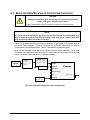
1
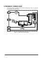
Manual Addendum Model T360U CO2 Analyzer (Addendum to T360 Manual, PN 07272) © TELEDYNE ADVANCED POLLUTION INSTRUMENTATION (TAPI) 9480 CARROLL PARK DRIVE SAN DIEGO, CA 92121-5201 USA Toll-free Phone: 800-324-5190 Phone: 858-657-9800 Fax: 858-657-9816 Email: [email protected] Website: http://www.teledyne-api.com/ Copyright 2013 Teledyne Advanced Pollution Instrumentation 07273A DCN6707 09 July 2013 ABOUT THIS ADDENDUM This addendum, part number 07273, is to be used in conjunction with the Model T360 operation manual, part number 07272. Where operation of the Model T360U diverges from that of the Model T360, this addendum takes precedence. Please note that the T360 operation manual contains important SAFETY messages and the WARRANTY information for this instrument. It is strongly recommended that you read the T360 operation manual in its entirety as well as this addendum, before operating the instrument. REVISION HISTORY Date Rev DCN 09 July 2013 A 6707 Change Summary T-Series initial release i This page intentionally left blank ii TABLE OF CONTENTS About This Addendum ................................................................................................................ i Revision History.......................................................................................................................... i Table of Contents ......................................................................................................................iii 1. Overview ........................................................................................................................... 5 2. Specifications and Agency Approvals ............................................................................... 5 3. Electrical Connections....................................................................................................... 6 4. Pneumatic Connections .................................................................................................... 7 4.1. Basic and Zero/Span Valve Option Configurations ....................................................... 8 4.2. Making the Pneumatic Connections............................................................................ 10 5. RelayAlarm Outputs (Standard configuration) ................................................................ 11 6. Relay Alarm Outputs (Air Products Configuration).......................................................... 11 7. Control inputs (Air Products Configuration only) ............................................................. 11 Figures Figure 4-1. T360U Pneumatic Flow Diagram............................................................................................... 7 Figure 4-2. Pneumatic Connections–Basic Configuration ............................................................................ 8 Figure 4-3. Pneumatic Connections–Configuration with Zero/Span Valve Option ....................................... 9 Tables Table 2-1. T360U Specifications and Agency Approvals.............................................................................. 5 Table 4-1. Model T360U Pneumatic Connections ........................................................................................ 9 Spare Parts List........................................................................................................................................... 13 iii This page intentionally left blank. iv 1. OVERVIEW The Model T360U is a close derivative of the Model T360 CO Analyzer. The main differences are as follows: The optical bench is longer (14 m), making the instrument more sensitive at low CO2 levels. The instrument has a user-selectable full scale range of 0-100 PPB to 0-100 PPM of CO2. The rear panel has an extra pneumatic port for the exhaust of the purge gas to the GFC wheel. Because the T360U is a close derivative of T360, the Model T360 Operation Manual continues to be valid as the reference manual covering the details of the instrument’s components and operation. 2. SPECIFICATIONS AND AGENCY APPROVALS Table 2-1 presents the specification parameters and values, as well as agency approvals. Table 2-1. T360U Specifications and Agency Approvals PARAMETER Ranges SPECIFICATION User selectable to any full scale range from 0-100 ppb to 0-100 ppm Measurement Units ppb, ppm, µg/m3, mg/m3 (user selectable) Zero Noise ≤ 2.5 ppb RMS(1) Span Noise < 0.5% of reading RMS over 5 ppm(1) (3) Lower Detectable Limit < 5 ppb(1) Zero Drift (24 hours) < 0.25 ppm(2) Span Drift (24 hours) < 0.5% of reading(2) (4) Linearity 1% of full scale (5) Precision 0.5% reading(1) (5) Lag Time <10 sec(1) Rise/Fall Time <60 sec to 95%(1) Sample Flow Rate 800 cc/min. ± 10% Temperature Range 5 - 40C operating Humidity Range 0-95% RH, Non-Condensing Temp Coefficient < 0.05 % of reading per C (5 ppb/C minimum) Voltage Coefficient < 0.05 % of reading per V Dimensions (HxWxD) 7" x 17" x 23.5" (178 mm x 432 mm x 597 mm) Weight 40 lb (18.1 kg) 5 PARAMETER AC Power SPECIFICATION 100 – 120V 50/60 Hz (120W) 220 – 240 V 50/60 Hz (144W) Environmental Conditions Installation Category (Over voltage Category) II Pollution Degree 2 Standard I/O 1 2 2 8 6 4 Optional I/O 1 USB com port 1 RS485 8 analog inputs (0-10V, 12-bit) 4 digital alarm outputs Multidrop RS232 3 4-20mA current outputs Analog Output Resolution 1 part in 4096 of selected full-scale voltage Certifications CE: IEC 61010-1:2001, EN61326 - Class A 1 2 3 4 5 Ethernet: 10/100Base-T RS-232 (300 – 115,200 baud) USB device ports opto-isolated digital status outputs opto-isolated digital control inputs analog outputs As defined by the USEPA At constant temperature and voltage Or 0.2 ppm, whichever is greater Or 0.1 ppm, whichever is greater Above 10 ppm range, otherwise 0.2 ppm for lower ranges 3. ELECTRICAL CONNECTIONS Follow the instructions for unpacking, inspecting, and making electrical connections presented in the T360 operation manual. 6 4. PNEUMATIC CONNECTIONS This section provides information on the pneumatic configurations. Figure 4-1 shows the basic pneumatic flow of the T360U. Figure 4-1. T360U Pneumatic Flow Diagram 7 4.1. BASIC AND ZERO/SPAN VALVE OPTION CONFIGURATIONS CAUTION Sample and calibration gases should only come into contact with PTFE (Teflon), FEP, glass, stainless steel or brass. Do NOT operate without first removing dust plugs from rear panel fixtures. NOTE To prevent dust from entering the gas flow channels, your analyzer was shipped with small plugs inserted into each of the pneumatic fittings on the back panel. Remove these dust plugs and store for future use before proceeding. Figure 4-2 illustrates the most common configuration for gas supply and exhaust lines to the Model T360U Analyzer. Figure 4-3 illustrates the pneumatic connections for optional configuration with zero/span valves. Table 4-1 describes the pneumatic ports. Note that the flowmeter could also be configured upstream of the instrument. Since most flowmeters are calibrated at ambient pressure, ensure that the flow going through the flow meter is at ambient pressure, when it is placed upstream. Sample/ Cal gas Pressure regulator (set to 10-15 psig output) Needle valve, set flow to 800 cc/min (+/- 10%) Flowmeter Sample Exhaust Chassis Vent Span Pressure Span Zero 10-30 psig CO2 free gas To Purge Figure 4-2. Pneumatic Connections–Basic Configuration 8 From Purge Sample gas Pressure regulator, set output to 5-10 psig Needle valve, set flow to 800 cc/min (+/- 10%) Sample Chassis Exhaust Flowmeter Vent Span Span gas CO2 free gas Needle valve, set flow to 800 cc/min (+/10%) Pressure Regulator (5-10 psig output) Needle valve, set flow to 800 cc/min (+/10%) Pressure Regular (5-10 psig output) Pressure Span Zero To Purge From Purge 10-30 psig CO2 free gas Figure 4-3. Pneumatic Connections–Configuration with Zero/Span Valve Option Rear Panel Label Table 4-1. Model T360U Pneumatic Connections Function SAMPLE Connect a gas line from the source of sample gas here. Calibration gasses are also inlet here on units without zero/span valve option installed. EXHAUST Connect an exhaust gas line of not more than 10 meters long here. PRESSURE SPAN On units with zero/span valve option installed, connect a gas line to the source of calibrated span gas here. VENT SPAN Not used ZERO On units with zero/span valve option installed, attach a gas line to the source of zero air here. TO PURGE This inlet supplies purge air to the GFC wheel housing Connect a source of dried air that has been scrubbed of CO2. FROM PURGE This exhausts purge air from the GFC wheel housing. Connect an exhaust gas line of not more than 10 meters long here. 9 4.2. MAKING THE PNEUMATIC CONNECTIONS CAUTION Venting should be outside the shelter or immediate area surrounding the instrument. 1. Attach a sample inlet line to the sample inlet port. The SAMPLE input line should not be more than 2 meters long. 2. Attach sources of zero air and span gas 3. Span Gas is a gas specifically mixed to match the chemical composition of the type of gas being measured at near full scale of the desired measurement range. In the case of CO2 measurements made with the Teledyne Instruments Model T360U Analyzer it is recommended that you use a gas calibrated to have a CO2 content equaling 80% of the range of compositions being measured. EXAMPLE: If the application is to measure between 0 ppm and 50 ppm, an appropriate Span Gas would be 40 ppm. If the application is to measure between 0 ppm and 100 ppm, an appropriate Span Gas would be 80 ppm. Zero Air is similar in chemical composition to the earths atmosphere but scrubbed of all components that might affect the analyzer’s readings. In the case of CO2 measurements this means CO2 less than 0.1 ppm of CO2 and Water Vapor. Zero Air can be purchased in pressurized canisters or created using a Teledyne Instruments Model 701 Zero Air Generator in combination with a canister of indicating soda-lime. 4. Attach an exhaust line to the exhaust outlet port. The exhaust from the analyser and vent lines should be vented to atmospheric pressure using maximum of 10 meters of ¼” PTFE tubing. 5. Attach a source of dried air scrubbed of CO2 to the purge inlet port The source of purge gas should be at least 10 psig and capable of maintaining a flow of at least 1 liter/min. Purge source gas pressure should not exceed 30 psig 6. Once the appropriate pneumatic connections have been made, check all pneumatic fittings for leaks. 10 5. RELAY ALARM OUTPUTS (STANDARD CONFIGURATION) There are 4 relay alarm outputs (AL1-AL4) on the rear panel. AL1 is for system okay, AL2 is for concentration limit 1 exceeded and AL3 is for concentration limit 2 exceeded. AL4 is not used The relay alarm output AL1 is enabled all the time, whereas the AL2 and AL3 can be enabled/disabled by going into the diagnostics menu (with 929 password), then factory options, then turning conc. Alarm Relays ON or OFF. When the concentration alarm relays are enabled, concentration alarms status is no longer available through the “Status output” pins. So, either the alarm relays or the status bits could be used to monitor the concentration alarms but not both at the same time. The default factory setting is to enable the concentration alarm relays. The AL1 relay is energized when the system is okay and de-energized when the system has a fault. The AL2 and AL3 relays energize when the corresponding concentration limits are exceeded. 6. RELAY ALARM OUTPUTS (AIR PRODUCTS CONFIGURATION) There are 4 relay alarm outputs (AL1-AL4) on the rear panel. AL1 is for “system okay”, AL2 is for “high range status” and AL3 is for “zero calibration status” AL4 is not used The AL1 relay is energized when the system is okay and de-energized when the system has a fault. The AL2 relay is energized when the high auto-range is in use and and AL3 relays energize when the the instrument is in zero calibration mode. 7. CONTROL INPUTS (AIR PRODUCTS CONFIGURATION ONLY) An additional control input is available on this instrument. Control input “C” is used to select the range for remote calibration. When input C is low, the instrument selects high range during contact closure calibration. 11 This page intentionally left blank. 12 T360U SPARE PARTS LIST Ref PN 07460, 05 Apr 2013, 14:24 PARTNUMBER 037600000 037860000 039060100 039260501 040010000 040030300 040370000 041350000 042680000 042690000 042890100 043250100 043250300 043250400 045930000 050110000 052560000 052830200 055010000 058021100 066970000 067240000 067300000 067300100 067300200 067900000 068810000 069500000 072150000 072850000 074610100 074620100 077480300 037250000 036110400 033560000 033520000 032960000 019340600 016910000 016300600 016290000 010800000 010790000 009840300 009690100 009690000 009560201 009550500 07273A DCN6707 DESCRIPTION AKIT, EXP KIT, SODA LIME CH47 ORING, TEFLON, RETAINING RING, 47MM (KB) ASSY, PRESSURE TRANSDUCER DETECTOR, CO2, w/BANDPASS FILTER* ASSY, FAN REAR PANEL (B/F) PCA, PRESS SENSORS w/SW49 ASSY, CO SCRUBBER PCA, RELAY BOARD, CO(KB) ASSY, VALVE (SS) ASSY, VALVE , 2-WAY, 12V ASSY, PUMP CONFIG PLUG, 100-115V/60 HZ ASSY, PWR CONF, 100-120V/60HZ, IR OPTION, PWR CONF, 220-240V/50HZ, IR OPTION, PWR CONF, 220-240V/60HZ, IR ASSY, PURGE REGULATOR THERMAL PAD, HEATSINK, CENTER PCA, OPTO-INTERRUPTER ASSY, MOTOR HUB, MR7 ASSY, MTR WHL HEATER w/THERM, 200W PCA, MOTHERBD, GEN 5-ICOP(KB) PCA, INTRF. LCD TOUCH SCRN, F/P CPU, PC-104, VSX-6154E, ICOP *(KB) PCA, AUX-I/O BD, ETHERNET, ANALOG & USB PCA, AUX-I/O BOARD, ETHERNET PCA, AUX-I/O BOARD, ETHERNET & USB LCD MODULE, W/TOUCHSCREEN(KB) PCA, LVDS TRANSMITTER BOARD PCA, SERIAL & VIDEO INTERFACE BOARD ASSY. TOUCHSCREEN CONTROL MODULE KIT, T360U MANUAL DOM, w/SOFTWARE, STD, T360U* DOM, w/SOFTWARE, STD,GFC7000TU,AIR PROD* ASSY, PMP, INT, Univ-V, 9 OC ASSY, STRIP HEATER PCA, SYNC DEMOD, (KB) MIRROR, FIELD, 32 PASS, (KB) MIRROR, OBJECT, 32 PASS, (KB) PCA, SYNC DEMOD, PROGRAM, LONG BENCH ASSY, SAMPLE THERMISTOR, SS AKIT, EXP KIT, CO CATALYST ASSY, SAMPLE FILTER, 47MM, ANG BKT, 5UM WINDOW, SAMPLE FILTER, 47MM (KB) OUTPUT MIRROR, REPLICATED(KB) INPUT MIRROR, REPLICATED(KB) ASSY, SHUT-OFF VALVE, (KB) AKIT, TFE FLTR ELEM (FL6, 30=1) 47mm AKIT, TFE FLTR ELEM (FL6 100=1) 47mm GF WHEEL, CO2, (KB) ASSY, SOURCE 13 T360U SPARE PARTS LIST Ref PN 07460, 05 Apr 2013, 14:24 009450300 006110200 003291500 003290500 001761300 001760400 000941000 000940600 077490300 CN0000073 CN0000458 CN0000520 FL0000001 HW0000020 HW0000036 HW0000090 HW0000101 HW0000379 HW0000453 HW0000685 KIT000219 OP0000009 OR0000001 OR0000002 OR0000034 OR0000039 OR0000041 OR0000047 OR0000077 OR0000088 OR0000094 OR0000096 OR0000097 PS0000011 PS0000024 PS0000025 PU0000022 SW0000025 SW0000026 VA0000014 WR0000008 14 ASSY, ZERO/SPAN VALVES, CO ASSY, MOTOR WHEEL HEATER ASSY, THERMISTOR, BENCH/WHEEL ASSY, THERMISTOR, BENCH ASSY, FLOW CTRL, .010, 1/8", SS ASSY, FLOW CTL, 800CC, 1/4" CONN-B CD, ORIFICE, .013 BLUE/GREEN (KB) CD, ORIFICE, .010 BROWN (KB) ASSY, PMP, INT, 100V, 9 OC POWER ENTRY, 120/60 (KB) PLUG, 12, MC 1.5/12-ST-3.81 (KB) PLUG, 10, MC 1.5/10-ST-3.81 (KB) FILTER, SS (KB) SPRING TFE TAPE, 1/4" (48 FT/ROLL) SPRING, SS, LONG ISOLATOR SEAL, GFC MOTOR SUPPORT, CIRCUIT BD, 3/16" ICOP LATCH, MAGNETIC, FRONT PANEL (KB) AKIT, 4-20MA CURRENT OUTPUT WINDOW (KB) ORING, 2-006VT *(KB) ORING, 2-023V ORING, 2-011V FT10 ORING, 2-012V (KB) ORING, 2-136V ORING, 2-007V ORING, 2-018V ORING, 2-011S, 40 DURO ORING, 2-228V, 50 DURO VITON(KB) ORING, 2-532V ORING, 2-119S PWR SUPPLY, SW, +5V, +/-15V, 40W (KB) COVER ENCLOSURE KIT,LPX 40/60 (KB) PWR SUPPLY, SW, 12V, 40W (KB) REBUILD KIT, FOR PU20 & 04241 (KB) SWITCH/CIR BRK, VDE, CE *(KB) SENSOR, PRES, 0-15, PSIA (OBS) REGULATOR POWER CORD, 10A 07273A DCN6707 Interconnect List, T360U Reference: 073640100A FROM Cable PN Signal Assembly PN J/P Pin 03995 CBL, MOTOR TO RELAY PCA GFC Drive - A Relay PCA 041350000 J6 1 GFC Drive - B Relay PCA 041350000 J6 2 Motor Return Relay PCA 041350000 J6 3 Chassis Gnd Relay PCA 041350000 J6 4 040230100CBL, I2C, RELAY BOARD TO MOTHERBOARD I2C Serial Clock Motherboard 058021100 P107 3 I2C Serial Data Motherboard 058021100 P107 5 I2C Reset Motherboard 058021100 P107 2 I2C Shield Motherboard 058021100 P107 6 04146 CBL, SYNC DEMOD DGND Opto Pickup 05032 or 05256 J2 1 Segmentg Gate Opto Pickup 05032 or 05256 J2 2 No Connection Opto Pickup 05032 or 05256 J2 3 DGND Opto Pickup 05032 or 05256 J2 4 M/R Gate Opto Pickup 05032 or 05256 J2 5 +5V Opto Pickup 05032 or 05256 J2 6 04671 CBL, MOTHERBOARD TO XMITTER BD (MULTIDROP OPTION) GND Motherboard 058021100 P12 2 RX0 Motherboard 058021100 P12 14 RTS0 Motherboard 058021100 P12 13 TX0 Motherboard 058021100 P12 12 CTS0 Motherboard 058021100 P12 11 RS-GND0 Motherboard 058021100 P12 10 RTS1 Motherboard 058021100 P12 8 CTS1/485Motherboard 058021100 P12 6 RX1 Motherboard 058021100 P12 9 TX1/485+ Motherboard 058021100 P12 7 RS-GND1 Motherboard 058021100 P12 5 RX1 Motherboard 058021100 P12 9 TX1/485+ Motherboard 058021100 P12 7 RS-GND1 Motherboard 058021100 P12 5 06737 CBL, I2C TO AUX I/O PCA (ANALOG IN OPTION) ATXMotherboard 058021100 J106 1 ATX+ Motherboard 058021100 J106 2 LED0 Motherboard 058021100 J106 3 ARX+ Motherboard 058021100 J106 4 ARXMotherboard 058021100 J106 5 LED0+ Motherboard 058021100 J106 6 LED1+ Motherboard 058021100 J106 8 06738 CBL, CPU COM to AUX I/O (USB OPTION) RXD1 CPU PCA 067240000 COM1 1 DCD1 CPU PCA 067240000 COM1 2 DTR1 CPU PCA 067240000 COM1 3 TXD1 CPU PCA 067240000 COM1 4 DSR1 CPU PCA 067240000 COM1 5 GND CPU PCA 067240000 COM1 6 CTS1 CPU PCA 067240000 COM1 7 RTS1 CPU PCA 067240000 COM1 8 RI1 CPU PCA 067240000 COM1 10 06738 CBL, CPU COM to AUX I/O (MULTIDROP OPTION) RXD CPU PCA 067240000 COM1 1 DCD CPU PCA 067240000 COM1 2 DTR CPU PCA 067240000 COM1 3 TXD CPU PCA 067240000 COM1 4 DSR CPU PCA 067240000 COM1 5 GND CPU PCA 067240000 COM1 6 CTS CPU PCA 067240000 COM1 7 RTS CPU PCA 067240000 COM1 8 RI CPU PCA 067240000 COM1 10 06739 CBL, CPU ETHERNET TO AUX I/O PCA ATXCPU PCA 067240000 LAN 1 ATX+ CPU PCA 067240000 LAN 2 LED0 CPU PCA 067240000 LAN 3 ARX+ CPU PCA 067240000 LAN 4 ARXCPU PCA 067240000 LAN 5 LED0+ CPU PCA 067240000 LAN 6 LED1 CPU PCA 067240000 LAN 7 LED1+ CPU PCA 067240000 LAN 8 06741 CBL, CPU USB TO LCD INTERFACE PCA GND CPU PCA 067240000 USB 8 LUSBD3+ CPU PCA 067240000 USB 6 LUSBD3CPU PCA 067240000 USB 4 VCC CPU PCA 067240000 USB 2 07273A DCN6707 Assembly TO PN J/P Pin GFC Motor GFC Motor GFC Motor GFC Motor 052380200 052380200 052380200 052380200 P1 P1 P1 P1 1 2 3 4 Relay PCA Relay PCA Relay PCA Relay PCA 041350000 041350000 041350000 041350000 P3 P3 P3 P3 1 2 4 5 Sync Demod Sync Demod Sync Demod Sync Demod Sync Demod Sync Demod 032960000 032960000 032960000 032960000 032960000 032960000 JP4 JP4 JP4 JP4 JP4 JP4 6 5 4 3 2 1 Xmitter bd w/Multidrop069500000 Xmitter bd w/Multidrop069500000 Xmitter bd w/Multidrop069500000 Xmitter bd w/Multidrop069500000 Xmitter bd w/Multidrop069500000 Xmitter bd w/Multidrop069500000 Xmitter bd w/Multidrop069500000 Xmitter bd w/Multidrop069500000 Xmitter bd w/Multidrop069500000 Xmitter bd w/Multidrop069500000 Xmitter bd w/Multidrop069500000 Xmitter bd w/Multidrop069500000 Xmitter bd w/Multidrop069500000 Xmitter bd w/Multidrop069500000 J4 J4 J4 J4 J4 J4 J4 J4 J4 J4 J4 J4 J4 J4 2 14 13 12 11 10 8 6 9 7 5 9 7 5 AUX I/O PCA AUX I/O PCA AUX I/O PCA AUX I/O PCA AUX I/O PCA AUX I/O PCA AUX I/O PCA 067300000 067300000 067300000 067300000 067300000 067300000 067300000 J2 J2 J2 J2 J2 J2 J2 1 2 3 4 5 6 8 AUX I/O PCA AUX I/O PCA AUX I/O PCA AUX I/O PCA AUX I/O PCA AUX I/O PCA AUX I/O PCA AUX I/O PCA AUX I/O PCA 0673000 or -02 0673000 or -02 0673000 or -02 0673000 or -02 0673000 or -02 0673000 or -02 0673000 or -02 0673000 or -02 0673000 or -02 J3 J3 J3 J3 J3 J3 J3 J3 J3 1 2 3 4 5 6 7 8 10 Xmitter bd w/Multidrop069500000 Xmitter bd w/Multidrop069500000 Xmitter bd w/Multidrop069500000 Xmitter bd w/Multidrop069500000 Xmitter bd w/Multidrop069500000 Xmitter bd w/Multidrop069500000 Xmitter bd w/Multidrop069500000 Xmitter bd w/Multidrop069500000 Xmitter bd w/Multidrop069500000 J3 J3 J3 J3 J3 J3 J3 J3 J3 1 2 3 4 5 6 7 8 10 AUX I/O PCA AUX I/O PCA AUX I/O PCA AUX I/O PCA AUX I/O PCA AUX I/O PCA AUX I/O PCA AUX I/O PCA 067300100 067300100 067300100 067300100 067300100 067300100 067300100 067300100 J2 J2 J2 J2 J2 J2 J2 J2 1 2 3 4 5 6 7 8 LCD Interface PCA LCD Interface PCA LCD Interface PCA LCD Interface PCA 066970000 066970000 066970000 066970000 JP9 JP9 JP9 JP9 15 Interconnect List, T360U Reference: 073640100A FROM Cable PN Signal Assembly PN J/P 06746 CBL, MB TO 06154 CPU GND Motherboard 058021100 P12 RX0 Motherboard 058021100 P12 RTS0 Motherboard 058021100 P12 TX0 Motherboard 058021100 P12 CTS0 Motherboard 058021100 P12 RS-GND0 Motherboard 058021100 P12 RTS1 Motherboard 058021100 P12 CTS1/485Motherboard 058021100 P12 RX1 Motherboard 058021100 P12 TX1/485+ Motherboard 058021100 P12 RS-GND1 Motherboard 058021100 P12 RX1 Motherboard 058021100 P12 TX1/485+ Motherboard 058021100 P12 RS-GND1 Motherboard 058021100 P12 06809 CBL ASSY, DC POWER TO MOTHERBOARD DGND Relay PCA 041350000 J14 +5V Relay PCA 041350000 J14 AGND Relay PCA 041350000 J14 +15V Relay PCA 041350000 J14 AGND Relay PCA 041350000 J14 -15V Relay PCA 041350000 J14 +12V RET Relay PCA 041350000 J14 +12V Relay PCA 041350000 J14 Chassis Gnd Relay PCA 041350000 J14 06810 CBL, DC POWER & SIGNAL DISTRIBUTION +12V RET Blower Fan 1 058790000 +12V Blower Fan 1 058790000 +12V RET Blower Fan 2 058790000 +12V Blower Fan 2 058790000 +5V LCD Interface PCA 066970000 J14 DGND LCD Interface PCA 066970000 J14 +5V LCD Interface PCA 066970000 J14 SDA LCD Interface PCA 066970000 J14 SCL LCD Interface PCA 066970000 J14 LCD Interface PCA 066970000 J14 DGND LCD Interface PCA 066970000 J14 Shield LCD Interface PCA 066970000 J14 +12V Ret Fan 040010000 P1 +12V Fan 040010000 P1 AGND Flow Module 0400303 or -09 J4 +15V Flow Module 0400303 or -09 J4 Cell Pressure Flow Module 0400303 or -09 J4 Pump Vaccum Flow Module 0400303 or -09 J4 Sample Flow Flow Module 0400303 or -09 J4 Shield Measure Sync Demod 032960000 J3 PD Temp Sync Demod 032960000 J3 Reference Sync Demod 032960000 J3 AGND Sync Demod 032960000 J3 Dark Switch Sync Demod 032960000 J3 Sync Error Sync Demod 032960000 J3 Etest Sync Demod 032960000 J3 06811 CBL ASSY, BENCH HEATER Wheel Heater Relay PCA 041350000 P3 AC Return Relay PCA 041350000 P3 Bench Htr, 115V Relay PCA 041350000 P3 Bench Htr, 230V Relay PCA 041350000 P3 AC Return Relay PCA 041350000 P3 Chassis Gnd Relay PCA 041350000 P3 06812 CBL, BLOWER HTR CONFIG Config Jumper Oven Htr 1 058810000 HTR1 Config Jumper Oven Htr 1 058810000 HTR1 Config Jumper Oven Htr 2 058810000 HTR2 Config Jumper Oven Htr 2 058810000 HTR2 Config Jumper Blower P4 Config Jumper Blower P4 Shield 06813 CBL, MOTHERBOARD TO THERMISTORS +5V Ref Motherboard 058021100 J27 Bench Temp Motherboard 058021100 J27 +5V Ref Motherboard 058021100 J27 Wheel Temp Motherboard 058021100 J27 +5V ref Motherboard 058021100 J27 +5V Ref Motherboard 058021100 J27 Sample Temp Motherboard 058021100 J27 Motherboard 058021100 J27 Motherboard 058021100 J27 16 Pin Assembly TO PN 2 14 13 12 11 10 8 6 9 7 5 9 7 5 Shield CPU PCA CPU PCA CPU PCA CPU PCA CPU PCA CPU PCA CPU PCA CPU PCA CPU PCA CPU PCA CPU PCA CPU PCA CPU PCA 1 2 3 4 5 6 7 8 10 1 2 1 2 1 2 3 5 6 7 8 10 1 2 3 6 4 2 5 J/P Pin 067240000 067240000 067240000 067240000 067240000 067240000 067240000 067240000 067240000 067240000 067240000 067240000 067240000 COM1 COM1 COM1 COM1 COM1 COM2 COM2 COM2 COM2 COM2 485 485 485 1 8 4 7 6 8 7 1 4 6 1 2 3 Motherboard Motherboard Motherboard Motherboard Motherboard Motherboard Motherboard Motherboard Motherboard 058021100 058021100 058021100 058021100 058021100 058021100 058021100 058021100 058021100 J15 J15 J15 J15 J15 J15 J15 J15 J15 1 2 3 4 5 6 7 8 9 Relay PCA Relay PCA Relay PCA Relay PCA Relay PCA Relay PCA Relay PCA Motherboard Motherboard Motherboard Relay PCA 041350000 041350000 041350000 041350000 041350000 041350000 041350000 058021100 058021100 058021100 041350000 J12 J12 J12 J12 J12 J11 J11 J106 J106 J106 J12 7 8 7 8 2 1 2 2 6 1 1 Relay PCA Relay PCA Relay PCA Relay PCA Motherboard Motherboard Motherboard Motherboard Motherboard Motherboard Motherboard Shield Motherboard Motherboard Motherboard 041350000 041350000 041350000 041350000 058021100 058021100 058021100 058021100 058021100 058021100 058021100 J11 J11 J11 J11 J109 J109 J109 J109 J109 J109 J109 7 8 3 4 5 6 2 9 4 1 3 058021100 058021100 058021100 J108 J108 J108 16 4 8 1 4 2 3 4 5 Wheel Heater Wheel Heater Bench Htr Bench Htr Bench Htr 055010000 055010000 037250000 037250000 037250000 P1 P1 P1 P1 P1 1 2 1 2 3 1 2 1 2 1 2 Blower Htr Config Plug059180000 Blower Htr Config Plug059180000 Blower Htr Config Plug059180000 Blower Htr Config Plug059180000 Blower Htr Config Plug059180000 Blower Htr Config Plug059180000 Blower Htr Config Plug059180000 PLUG PLUG PLUG PLUG PLUG PLUG PLUG 1 2 4 5 4 2 3 6 13 5 12 1 7 14 2 9 Bench Temp Snsr Bench Temp Snsr Wheel Temp Snsr Wheel Temp Snsr Shield Sample Temp Snsr Sample Temp Snsr Oven Thermistor Oven Thermistor 003290500 003290500 003291500 003291500 P1 P1 P1 P1 1 2 1 2 019340600 019340600 058800000 058800000 P1 P1 P1 P1 1 2 1 2 1 2 5 6 4 7 8 07273A DCN6707 Interconnect List, T360U Reference: 073640100A FROM Cable PN Signal Assembly PN 06814 CBL ASSY, SYNC DEMOD , DC POWER DGND Relay PCA 041350000 +5V Relay PCA 041350000 AGND Relay PCA 041350000 +15V Relay PCA 041350000 AGND Relay PCA 041350000 -15V Relay PCA 041350000 +12V ret Relay PCA 041350000 +12V Relay PCA 041350000 06815 CBL ASSY, AC POWER AC Line Power Entry CN0000073 AC Neutral Power Entry CN0000073 Power Grnd Power Entry CN0000073 Power Grnd Power Entry CN0000073 AC Line Switched Power Switch SW0000025 AC Neu Switched Power Switch SW0000025 Power Grnd Power Entry CN0000073 AC Line Switched Power Switch SW0000025 AC Neu Switched Power Switch SW0000025 Power Grnd Power Entry CN0000073 AC Line Switched Power Switch SW0000025 AC Neu Switched Power Switch SW0000025 Power Grnd Power Entry CN0000073 06816 CBL ASSY, DC POWER +15 PS1 068010000 +5 PS1 068010000 DGND PS1 068010000 AGND PS1 068010000 -15 PS1 068010000 +12 PS2 068020000 +12 RET PS2 068020000 06817 CBL, RELAY BD TO SOURCE IR Source Drv Relay PCA 041350000 IR Source Drv Relay PCA 041350000 06818 CBL ASSY, 12V VALVE CBLS +12 Relay PCA 041350000 Zero/Span Drv Relay PCA 041350000 +12 Relay PCA 041350000 Samp/Cal Drv Relay PCA 041350000 +12 Relay PCA 041350000 Shutoff Vlv Relay PCA 041350000 +12 Relay PCA 041350000 Aref Valve Relay PCA 041350000 WR256 CBL, TRANSMITTER TO LCD INTERFACE PCA LCD Interface PCA 066970000 07273A DCN6707 J/P J15 J15 J15 J15 J15 J15 J15 J15 Pin Assembly 1 2 3 4 5 6 7 8 Sync Demod Sync Demod Sync Demod Sync Demod Sync Demod Sync Demod Blower Fan Blower Fan TO PN J/P Pin 032960000 032960000 032960000 032960000 032960000 032960000 058780000 058780000 J2 J2 J2 J2 J2 J2 J1 J1 1 2 3 4 5 6 1 2 L Power Switch N Power Switch Shield Chassis L PS2 (+12) N PS2 (+12) PS2 (+12) L PS1 (+5, ±15) N PS1 (+5, ±15) PS1 (+5, ±15) L Relay N Relay Relay 068020000 068020000 068020000 068010000 068010000 068010000 041350000 041350000 041350000 SK2 SK2 SK2 SK2 SK2 SK2 J1 J1 J1 1 3 2 1 3 2 1 3 2 SK1 SK1 SK1 SK1 SK1 SK1 SK1 6 1 3 4 5 1 3 Relay PCA Relay PCA Relay PCA Relay PCA Relay PCA Relay PCA Relay PCA 041350000 041350000 041350000 041350000 041350000 041350000 041350000 J13 J13 J13 J13 J13 J13 J13 4 3 1 5 6 8 7 J16 J16 1 2 IR Source IR Source 009550500 009550500 P1 P1 1 2 J7 J7 J7 J7 J7 J7 J7 J7 6 8 2 4 1 3 5 7 Zero/Span Vlv Zero/Span Vlv Samp/Cal Vlv Samp/Cal Vlv Shutoff Valve Shutoff Valve Autoref Valve Autoref Valve 009450500 009450500 009450400 009450400 009450500 009450500 009450500 009450500 P1 P1 P1 P1 P1 P1 P1 P1 1 2 1 2 1 2 1 2 Transmitter PCA 068810000 J1 J15 SW0000025 SW0000025 L N 17 This page intentionally left blank. 18 07273A DCN6707 07273A DCN6707 19