1
Operating Instructions
MEW01741
Revision -
Fire Alarm System EBL128
V2.1.x
Author:
Jan Pettersson
Date of issue: 2014-05-02
Date of rev:
This page has deliberately been left blank.
Panasonic Eco Solutions Nordic AB
MEW01741
Rev: -
EBL128 Operating Instructions V2.1.x
Table of contents
1
2
Introduction________________________________ 7
Definitions / Explanations ____________________ 9
2.1
2.2
PESN AB ________________________________________ 9
Alarm point _______________________________________ 9
2.2.1
Smoke detector ________________________________ 9
2.2.2
Sensor _______________________________________ 9
2.2.3
Analog detector ________________________________ 9
2.2.4
(Analog) Sensor Base (ASB) _____________________ 9
2.2.5
Conventional detector ___________________________ 9
2.2.6
Conventional Detector Base (CDB) ________________ 9
2.2.7
Addressable ___________________________________ 9
2.2.8
Old detector __________________________________ 10
2.2.9
Conventional zone line _________________________ 10
2.2.10 Addressable zone interface ______________________ 10
2.3
Output unit ______________________________________ 10
2.4
Output / Control output _____________________________ 10
2.5
Short circuit isolator _______________________________ 10
2.6
Display unit (D.U.) ________________________________ 10
2.7
COM loop _______________________________________ 10
2.8
Control Unit (C.U.) / C.I.E. __________________________ 10
2.9
Fire Brigade Panel (FBP) ___________________________ 10
2.10 Control panel (CP) ________________________________ 11
2.11 LED ____________________________________________ 11
2.12 External Indicator (LED) ___________________________ 11
2.13 Display / LCD ____________________________________ 11
2.14 Door open / Key switch_____________________________ 11
2.15 Site Specific Data (SSD) ____________________________ 11
2.16 Software (S/W) / Firmware / System program ___________ 11
2.17 EBLWin ________________________________________ 11
2.18 Web-server ______________________________________ 11
3
Overview _________________________________ 12
3.1
3.2
3.3
3.4
3.5
The EBL128 c.i.e. _________________________________ 12
S/W versions _____________________________________ 12
Documents ______________________________________ 12
Applications _____________________________________ 12
PC S/W _________________________________________ 12
4
5
6
Control & Indicating Equipment _____________ 14
LED indicators and push buttons _____________ 16
Normal operation __________________________ 21
6.1
The display in EBL128 _____________________________ 21
6.1.1
LCD backlight ________________________________ 21
1
Panasonic Eco Solutions Nordic AB
MEW01741
Rev: -
EBL128 Operating Instructions V2.1.x
6.1.2
The LCD information priority order _______________ 21
7
User level, User name & Password ____________ 23
7.1
7.2
7.3
7.4
7.5
7.6
7.7
User level 1 ______________________________________ 24
User level 2A_____________________________________ 24
User level 2B _____________________________________ 25
User level 2C _____________________________________ 26
User level 3A_____________________________________ 27
Access level 3B ___________________________________ 27
Access level 4 ____________________________________ 28
8
Silence Alarm devices _______________________ 29
8.1
8.2
Silence alarm devices (inside switch) __________________ 30
New Zealand FB Silence switch (outside switch) _________ 30
9
10
Disable / Re-enable alarm devices _____________ 32
"Silence buzzer" ___________________________ 33
10.1
Buzzer __________________________________________ 33
11
Disable / Re-enable all control, extinguishing,
ventilation and interlocking outputs ________________ 34
12
Evacuate, Alert Annunciation Acknowledge and
Disable ________________________________________ 35
12.1
12.2
12.3
Evacuate ________________________________________ 35
Alert Annunciation Acknowledge_____________________ 35
Disable _________________________________________ 35
13
German functions / units ____________________ 36
13.1 Push-button "ÜE prüfen" ___________________________ 36
13.2 Button "Brandfall Steuerungen ab" ____________________ 36
13.3 Indication "Brandfall Steuerungen ab" _________________ 37
13.4 Button "Akustische Signale ab" ______________________ 37
13.5 Indication "Akustische Signale ab" ____________________ 37
13.5.1 Indication in button "Akustische Signale ab" ________ 37
13.6 The buzzer in the c.i.e. _____________________________ 37
13.7 Button "ÜE ab" ___________________________________ 37
13.8 Indication "ÜE ab" ________________________________ 38
13.9 Disablements of outputs; Information in the c.i.e. and FAT
display respectively. _____________________________________ 38
14
Door open ________________________________ 39
14.1
14.2
14.3
LED "Door open" _________________________________ 39
Outputs for routing equipment (Fire brigade tx and Fault tx) 39
Silence buzzer ____________________________________ 39
15
Technical address / Presentation number ______ 40
15.1
15.2
Technical address for COM loop units _________________ 40
Presentation number _______________________________ 40
16
Alarm types _______________________________ 41
16.1
Pre-warning ______________________________________ 41
2
Panasonic Eco Solutions Nordic AB
MEW01741
Rev: -
EBL128 Operating Instructions V2.1.x
16.2 Fire alarm _______________________________________ 42
16.2.1 Fire alarm menu (X1-X9) _______________________ 45
16.2.2 Alert Annunciation alarm (AA alarm) _____________ 48
16.3 Heavy smoke alarm / Heavy heat alarm ________________ 49
16.4 Key cabinet alarm _________________________________ 50
16.4.1 Key cabinet opened before a fire alarm_____________ 50
16.4.2 Key cabinet opened in conjunction with a fire alarm __ 50
16.5 Quiet alarm ______________________________________ 50
16.6 Co-incidence alarm (two-unit / -zone dependence) _______ 51
16.7 Delayed alarm ____________________________________ 51
16.8 Alarm Acknowledgement Facility (AAF)_______________ 52
17
Alarm reset _______________________________ 54
17.1 Pre-warning reset _________________________________ 54
17.2 Fire alarm reset ___________________________________ 54
17.2.1 All _________________________________________ 54
17.2.2 Single_______________________________________ 54
17.2.3 Single with automatic disablement ________________ 55
17.3 Alert Annunciation alarm reset _______________________ 55
17.4 Co-incidence alarm reset ____________________________ 56
17.5 Heavy smoke / heat alarm reset ______________________ 56
17.6 Key cabinet alarm reset _____________________________ 56
17.7 Quiet alarm reset __________________________________ 56
17.8 Alarm Acknowledgement Facility (AAF) reset __________ 56
17.9 Acknowledged alarm ______________________________ 57
17.10
Isolated alarm __________________________________ 57
17.11
Delayed alarm __________________________________ 57
18
Fault _____________________________________ 58
18.1
18.2
Fault messages ___________________________________ 59
Fault acknowledge ________________________________ 74
19
20
Commissioning an EBL128 __________________ 75
SSD programming & download ______________ 76
20.1
20.2
20.3
20.4
SSD programming _________________________________ 76
Auto generating SSD_______________________________ 76
SSD download____________________________________ 76
Download of Alarm texts ___________________________ 78
21
Software (S/W) download ___________________ 79
21.1
21.2
21.3
Download of S/W in EBL128 (c.i.e.) __________________ 79
Earlier S/W version download _______________________ 80
S/W download in Display Units ______________________ 80
22
Restart ___________________________________ 81
22.1
Boot menu _______________________________________ 83
23
24
Access ____________________________________ 85
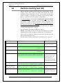
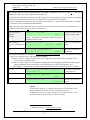
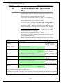
Perform monthly test (H1) ___________________ 87
3
Panasonic Eco Solutions Nordic AB
MEW01741
Rev: -
25
EBL128 Operating Instructions V2.1.x
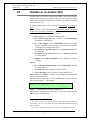
Disable or re-enable (H2) ____________________ 89
25.1 Disable zone (H2/B1) ______________________________ 90
25.2 Disable zone / address (H2/B2) _______________________ 91
25.3 Disable output (H2/B3) _____________________________ 92
25.4 Disable all control, ventilation, exting or interlocking outputs
(H2/B4) _______________________________________________ 94
25.5 Re-enable zone (H2/B5) ____________________________ 95
25.6 Re-enable zone / address (H2/B6)_____________________ 96
25.7 Re-enable output (H2/B7) ___________________________ 97
25.8 Re-enable all control, ventil, exting or interlocking outputs
(H2/B8) _______________________________________________ 99
25.9 Disable / re-enable alarm devices (H2/B9) _____________ 100
25.10
Disable / re-enable outputs for routing equipment (H2/B10)101
25.11
Disable / re-enable alert annunciation function (H2/B11) 102
26
Set calendar and clock (H3) _________________ 103
26.1
Daylight saving time ______________________________ 104
27
Present system status (H4) __________________ 105
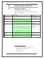
27.1 Disablement (H4/U1) _____________________________ 105
27.2 Disablement by time channel (H4/U2) ________________ 106
27.3 Sensor values (H4/U3) ____________________________ 107
27.3.1 Reset of a week average sensor value _____________ 110
27.4 Sensors activating SERVICE signal (H4/U4) ___________ 111
27.5 Technical warning (H4/U5) ________________________ 112
27.6 Event log (H4/U6) ________________________________ 113
27.7 Version and alarm counter (H4/U7) __________________ 114
28
Service (H5) ______________________________ 115
28.1
28.2
28.3
28.4
28.5
28.6
28.7
28.8
28.9
28.10
Calibration of supervised outputs (H5/A1) _____________ 116
Sensitive fault detection mode (H5/A2) _______________ 118
Service mode for COM-loop (H5/A3) ________________ 119
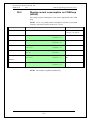
Display current consumption in unit (H5/A4)___________ 121
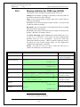
Display current consumption on COM-loop (H5/A5) ____ 122
Display statistics for COM loop (H5/A6) ______________ 123
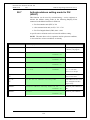
Activate address setting mode for DU (H5/A7) _________ 124
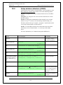
Setup wireless detectors (H5/A8) ____________________ 125
End setup wireless detectors (H5/A9) _________________ 126
Show information about Site Specific Data (H5/A10) __ 127
29
30
31
FAULT Acknowledge (H6) _________________ 129
Perform ZONE TEST (test mode) (H7) _______ 130
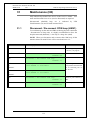
Maintenance (H8) _________________________ 132
31.1 Disconnect / Re-connect COM loop (H8/S1) ___________ 132
31.2 Disconnect / Re-connect zone line input (H8/A2) _______ 133
31.3 Disconnect / Re-connect addressable zone interface input
(H8/S3) ______________________________________________ 134
31.4 Acknowledge SERVICE signal (H8/S4)_______________ 135
4
Panasonic Eco Solutions Nordic AB
MEW01741
Rev: -
EBL128 Operating Instructions V2.1.x
31.5
31.6
31.7
31.8
31.9
31.10
Restore weekly average to default (H8/S5)_____________ 136
Test of alarm devices (H8/S6) _______________________ 137
Safe shut down of control unit (H8/S7) _______________ 138
Activate zone-address in alarm mode (H8/S8) __________ 139
Activate output (H8/S9) ___________________________ 141
Reset activated output (H8/S10) ___________________ 143
32
Interlocking outputs and inputs (H9) _________ 144
32.1
32.2
32.3
32.4
32.5
Activated interlocking outputs/inputs (H9/C1) __________ 144
Activate interlocking output (H9/C2) _________________ 145
Reset interlocking output (H9/C3) ___________________ 146
Disable interlocking output (H9/C4) __________________ 147
Re-enable interlocking output (H9/C5) ________________ 148
33
34
35
36
37
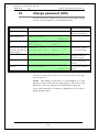
Change password (H10) ____________________ 149
Annual control ___________________________ 150
Battery maintenance _______________________ 151
How to avoid unnecessary (nuisance) fire alarms 152
Revision history ___________________________ 154
5
Panasonic Eco Solutions Nordic AB
MEW01741
Rev: -
EBL128 Operating Instructions V2.1.x
This page has deliberately been left blank.
6
Panasonic Eco Solutions Nordic AB
MEW01741
Rev: -
1
EBL128 Operating Instructions V2.1.x
Introduction
EBL128 Operating Instructions is a document1 intended to be used
by the end-user and the fire brigade personnel as well as service /
commissioning engineers.
It could be read in conjunction with the EBL128 Planning
Instructions, since most of the information in one of the documents is
not found in the other document and vice versa.
It should also be read in conjunction with the EBL128 drawings2,
according to the valid Table of drawings.
Product Leaflets are also available at:
http://pesn.panasonic.se
(Data sheets)
When planning a fire alarm installation the national regulations have
to be obeyed. A lot of detector types can be used. Detector coverage
area and detector placing in the room / building, etc. are matters for
the planning engineers and are not described in this document.
Due to continual development and improvement, different S/W
versions are to be found. This document is valid for the EBL128 S/W
version 2.1.x. On the date of this document is x=0.
EBL128 S/W version 2.1.x support and some functions require the
EBL128 main board 4556 with p.c.b. no. 9285-6A. This S/W version
also support main board with p.c.b. no. <9285-6A (e.g. 9285-5A).
EBL128 is produced for many countries, accordingly the look, the
texts, the functions, etc. might vary from country to country.
Products
Products consists of one or more parts (H/W) according to a Product
Parts List. A product has:
a type number (e.g. 4550)
an article number, often the same as the type no. but sometimes
a country code is added (e.g. 4550SE)
a product name (e.g. EBL128 Control & Indicating
Equipment, 128 addresses)
H/W
A H/W (e.g. a printed circuit board) has:
a type number (e.g. 4556)
an article number, often the same as the type no. but sometimes a
country code is added (e.g. 4556SE)
a product name (e.g. Main Board 255 addr.)
1
2
File name: L:\User documents\128\Doc\V2.1.x\MEW01741 (Rev -).doc
Dimensions & overviews, connection diagrams, etc.
7
Panasonic Eco Solutions Nordic AB
MEW01741
Rev: -
EBL128 Operating Instructions V2.1.x
a p.c.b. number (e.g. 9285-6A) and can also have a configuration
(e.g. CFG: 1) and a revision (e.g. REV: 2)
sometimes is a S/W (software) downloaded.
S/W
A S/W has:
a version number (e.g. V2.1.0)
sometimes is additional information, such as Convention
(different functions / facilities), Language, etc. added.
PC S/W
A PC S/W is a program used for programming, commissioning, etc. It
has a version number.
8
Panasonic Eco Solutions Nordic AB
MEW01741
Rev: -
2
EBL128 Operating Instructions V2.1.x
Definitions / Explanations
Definitions / explanations / abbreviations / etc. frequently used or not
explained elsewhere in the document.
2.1
PESN AB
Panasonic Eco Solutions Nordic AB
2.2
Alarm point
Unit, which can generate a fire alarm, i.e. an analog or conventional
detector, a manual call point, etc.
2.2.1
Smoke detector
One type of analog and conventional smoke detectors is available: the
photo electric (optical) smoke detector.
2.2.2
Sensor
Sensor = Analog detector
2.2.3
Analog detector
Contains an A/D-converter. EBL128 picks up the digital values
("sensor values") for each detector individually. All evaluations and
"decisions" are then made in EBL128, i.e. by advanced alarm
algorithms. As from version 2.0.x the latest detector generation
(440x) can be used. In the "Advanced mode" the alarm algorithms are
stored in the detector instead of the control unit. Analog detectors are
addressable – an address setting tool is used for address and mode
settings. An analog detector has to be plugged in an ASB.
2.2.4
(Analog) Sensor Base (ASB)
A sensor is plugged in an ASB, which is connected to a COM loop
(see below).
2.2.5
Conventional detector
Detector with two statuses, normal or fire alarm. The detector
contains a closing contact and a series alarm resistor. Normally
plugged in a conventional detector base CDB (see below), which is
connected to a conventional zone line input. Some types are water
proof and are not plugged in any base. An end-of-line device is
connected in the last unit on the conventional zone line.
2.2.6
Conventional Detector Base (CDB)
A conventional detector is plugged in a CDB and connected to a
conventional zone line input.
2.2.7
Addressable
A unit with a built-in address device (e.g. a manual call point). Each
unit is individually identified, handled and indicated in EBL128.
9
Panasonic Eco Solutions Nordic AB
MEW01741
Rev: -
EBL128 Operating Instructions V2.1.x
(The unit can consequently be an I/O unit, to which one or more
conventional "alarm points" can be connected on the zone line.).
2.2.8
Old detector
Conventional detector with a closing contact (short circuit; no alarm
resistor), or detector with two breaking contacts.
2.2.9
Conventional zone line
Zone line input on e.g. an I/O unit, intended for one or more
conventional alarm points. End-of-line device in the last alarm point.
2.2.10
Addressable zone interface
Unit with a zone line input, intended for one or more conventional
alarm points. End-of-line device in the last alarm point.
2.3
Output unit
Addressable unit with programmable control outputs (e.g. an I/O unit).
To be connected to a COM loop (see below).
2.4
Output / Control output
Defined or programmable function. Relay or (supervised / monitored)
voltage output, in EBL128 or an output unit.
2.5
Short circuit isolator
Addressable unit for automatic isolation of a segment on a COM loop
(see below) in case of short circuit on the loop.
2.6
Display unit (D.U.)
Unit for fire alarm presentation (incl. alarm texts, if programmed).
Connected to an RS485 line.
2.7
COM loop
Loop = a cable (a twisted pair), to which all the addressable Panasonic
COM loop units can be connected. It starts in EBL128 and it returns
back to EBL128.
2.8
Control Unit (C.U.) / C.I.E.
Control Unit = C.U. = Control and Indicating Equipment (c.i.e.) = A
unit, e.g. EBL128, to which the alarm points are connected. Indicates
fire alarm, fault condition, etc. on the front, i.e. on the Fire Brigade &
Control Panel (see below).
2.9
Fire Brigade Panel (FBP)
The Fire Brigade Panel is a part of the EBL128 front, intended for fire
alarm presentation, etc. for the fire brigade personnel. A separate unit;
an external FBP, can also be connected to EBL128.
10
Panasonic Eco Solutions Nordic AB
MEW01741
Rev: -
EBL128 Operating Instructions V2.1.x
In the ext. FBP a printer can be included.
2.10
Control panel (CP)
The Control Panel is a part of the EBL128 front, intended for the
building occupier, service personnel, etc. to "communicate" with
EBL128 / the system.
2.11
LED
LED (Light Emitting Diode) = Yellow, green or red optical indicator
("lamp").
2.12
External Indicator (LED)
A unit with an LED. Connected to an ASB, CDB or a detector with a
built-in LED, for external indication. Lit when the built-in LED is lit.
2.13
Display / LCD
LCD (Liquid Crystal Display) = Display for presentation of fire
alarms, fault messages, etc. Normally alphanumeric characters and
backlight.
2.14
Door open / Key switch
A door / key switch, which has to be activated in order to get access to
the push buttons on the front. Indicated by the LED "Door open".
2.15
Site Specific Data (SSD)
This data is unique for each installation. All alarm points,
presentation numbers, alarm texts, programmable outputs, etc. are
programmed (configured) in the PC program EBLWin and has to be
downloaded in EBL128.
2.16
Software (S/W) / Firmware / System
program
The S/W makes EBL128 (the microprocessor) work. It is factory
downloaded but a new version can via the PC program EBLWin be
downloaded in EBL128 on site.
2.17
EBLWin
PC program used to create and download the SSD in EBL128 unit.
Also used to download another / new software version.
Can be used during commissioning / maintenance of the EBL128
system (autogenerate COM loop SSD, acknowledge faults, etc.).
2.18
Web-server
The Web-server is used to get EBL128 information as well as remote
control via a PC (browser) and an intranet / internet. The Web-server
is configured via the PC tool EBLWin.
11
Panasonic Eco Solutions Nordic AB
MEW01741
Rev: -
EBL128 Operating Instructions V2.1.x
3
Overview
3.1
The EBL128 c.i.e.
EBL128 is a microprocessor controlled intelligent fire alarm Control
and Indicating Equipment (c.i.e.) intended for analog addressable
smoke and heat detectors. Also conventional detectors and manual
call points can be used. Programmable inputs, control outputs and I/O
units are available. Up to 255 addresses can be connected to EBL128.
EBL128 is fully compliant with the European standard EN54 parts 2
and 4 and the front is fully SS3654 compliant.
3.2
S/W versions
Due to continual development and improvement, different S/W
versions can be found. You can update the S/W in EBL128 on site.
3.3
Documents
The following documents are available:
Planning instructions
Drawings
Operating instructions
Information found in one document is normally not to be found in
another document, i.e. the documents complement each other.
Product Leaflet for EBL128 and other units are available as pdf
documents on our web site: http:/pesn.panasonic.se
3.4
Applications
EBL128 is intended for small and medium installations. The
intelligent control unit offer the system designer and end user a
technically sophisticated range of facilities and functions.
Programming (via PC S/W EBLWin) and commissioning is very
easy.
3.5
PC S/W
EBLWin is used for programming and commissioning, i.e. to:
create / download / upload (backup) the site specific data (SSD)
download new S/W version, language (text file), EBL128 settings
(e.g. convention), etc.
create / download the alarm texts shown in the display in EBL128,
ext. FBP and/or AA units.
The EBLWin S/W shall have the same version number as the EBL128
S/W version number, e.g. 2.1.x. Only x may be different. Old SSD
files can be used with a newer EBL128 S/W version. Open and save
the old SSD file in the new EBLWin version before the download. If
12
Panasonic Eco Solutions Nordic AB
MEW01741
Rev: -
EBL128 Operating Instructions V2.1.x
a backup is required, use the same EBLWin version as the EBL128
version.
EBLWin key 5094 is a USB unit that has to be plugged in the PC in
order to log on to the c.i.e.
13
Panasonic Eco Solutions Nordic AB
MEW01741
Rev: -
4
EBL128 Operating Instructions V2.1.x
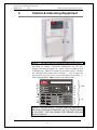
Control & Indicating Equipment
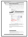
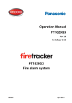
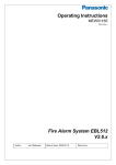
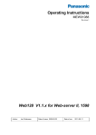
Figure 1. The EBL128 Control & Indicating Equipment (4550).
Depending on country, convention, configuration, etc. the look,
language and functions might vary. Figure 1 shows an EBL128 with
an English front. EBL128 is housed in a grey metal cabinet. The door
has a Plexiglas ahead of the front, see Figure 1. A key is required to
open the door to get full access to the push buttons on the front, i.e.
the Fire Brigade Panel (FBP) and the Control Panel (CP).
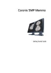
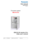
FBP
CP
Figure 2. The EBL128 front. The look might vary depending on
the country (language) configuration, etc. (e.g. English texts as
in the figure). See also chapter "LED indicators and push
buttons", page 16.
14
Panasonic Eco Solutions Nordic AB
MEW01741
Rev: -
EBL128 Operating Instructions V2.1.x
The FBP is used by the fire brigade personnel to see which alarm
point / zone having activated the fire alarm(s), silence alarm devices,
reset alarms, etc. In the display (LCD, 2x40 alphanumeric characters),
the information displayed on the first row is depending on how many
alarm points / zones having activated fire alarm, convention and
language.
On the second row is, for the activated alarm point / zone, an alarm
text shown, if programmed. See chapter "Fire alarm", page 42.
Required fire brigade personnel manoeuvres are performed via the
FBP in EBL128 or via an external FBP 1826 / 1828.
Instead of external FBPs 1826 / 1828, the German Fire Brigade
Control Panels (Feuerwehr-Bedienfeld) FBF 2003 and/or German
Fire Brigade Indicator Panels (Feuerwehr-Anzeigetableau) FAT 2002
can be used.
The CP is used by the EBL128 owner, service personnel, etc. to
"communicate" with EBL128, e.g. for monthly tests, disablements
commissioning, maintenance and service. Access codes for different
users and access levels are required. A keypad is used to get access to
the menu tree, i.e. main and sub menus for data input / output,
manoeuvres, etc. The CP also holds several system status LEDs.
15
Panasonic Eco Solutions Nordic AB
MEW01741
Rev: -
5
EBL128 Operating Instructions V2.1.x
LED indicators and push buttons
LEDs and push buttons can vary according to configuration /
convention / country / language.
See also Figure 2, page 14.
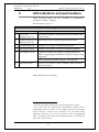
LED indicators on the Fire Brigade Panel (FBP)
LED indicator
Indicating
L1
Fire (5 red)
Blinking (0.4/0.4s)
Fire alarm (also heavy smoke/heat alarm, Quiet alarm & key
cabinet alarm) 3
L2
Alarms queued (2 red)
Blinking (0.4/0.4s)
More than one unit / zone have generated fire alarm.
L3
Extinguishing (red)
Output(s) activated for extinguishing equipment. 4
L4
Ventilation (yellow)
Output(s) activated for fire/smoke ventilation equipment. 4
L5
Fire brigade tx (red)
Output activated for Fire brigade tx (routing equipment)
and/or corresponding programmable output(s) of type routing
equipment. 4
Test of routing equipment in progress (see menu H1).
L6
Operation (green)
Power on, i.e. EBL128 is power supplied via the rectifier or
the backup battery.
(FBP push buttons on next page)
3
In the New Zealand convention also "Acknowledged alarm" (ACK).
L3, L4 and L5 can as an alternative be programmed to indicate when a
programmable input is activated, i.e. input trigger condition "Extinguishing
system released", "Activated fire ventilation" and "Activated routing
equipment" respectively (e.g. L5 can be turned on when a programmable
input is activated by an activated routing equipment output). L5 is turned on
until all fire alarms are reset.
4
16
Panasonic Eco Solutions Nordic AB
MEW01741
Rev: -
EBL128 Operating Instructions V2.1.x
Push buttons on the Fire Brigade Panel (FBP)
Push button
Operation/function
P1
Alarms queued (black)
Used, when LEDs "Alarms queued" (L2) are lit, to
scroll/browse through the queued alarms (zones).
P2
Silence buzzer
(yellow)
Used to silence the buzzer in EBL128
P3
Silence Alarm devices
(red)5
Used to silence the sounders (i.e. to "reset" outputs for alarm
devices).6
P4
Reset (green)
Used to reset the fire alarm(s).7 Has to be pressed for > 0.5
sec.
P5
Evacuate (green) 8
Used to activate all the sounders (i.e. the outputs for alarm
devices).
Alert Annunciation
Acknowledge (green) 9
Used to acknowledge an Alert Annunciation alarm.
Disable (yellow) 10
Used to disables all zones in alarm state.
5
In the New Zealand convention = The "inside switch".
Via EBLWin can be set if the alarm devices shall be continuous off /
disabled or re-sound for a new alarm.
7
Single reset: The fire alarm displayed in the LCD (first row to the left)
will be reset. When more than one fire alarm is activated (LEDs "Alarms
queued" are lit) each fire alarm has to be individually reset.
Multiple reset (Default): All fire alarms will be reset simultaneously.
Single encapsulated reset: Like Single reset but with the Encapsulation
function, which is described in chapter "Single with automatic disablement",
page 55.
NOTE (1)! When "Multiple reset" is used, encapsulated reset can be done
by pressing "Reset" (P4) and 0.1 sec. later also press "Alarms queued" (P1)
and hold them pressed for > 0.5 sec. The fire alarm displayed in the LCD
(first row to the left) will be encapsulated or the points in alarm status within
one zone will be encapsulated or the whole zone (conventional) will be
encapsulated.
NOTE (2)! When "Single encapsulated reset" is used, you can make a
"Multiple reset" by pressing "Reset" (P4) and 0.1 sec. later also press "A" (in
the keypad) and hold them pressed for > 0.5 sec.
8
"Evacuate" is only valid in the "Belgian", Brittish Standard, Hungarian,
Spanish and "Ukrainian" conventions.
9
"Alert Annunciation Acknowledge" is only valid in the "Czech", Bulgarian
and "Polish" conventions.
10
"Disable" is only valid in the "Australian" and New Zealand conventions.
6
17
Panasonic Eco Solutions Nordic AB
MEW01741
Rev: -
EBL128 Operating Instructions V2.1.x
(CP LED indicators on next page)
LED indicators on the Control Panel (CP)
LED indicator
Indicating
L7
General fault (yellow)
Fault(s), i.e. not acknowledged fault(s) and/or
acknowledged but not corrected fault(s).
L8
Disablements (yellow)
Something is disabled / disconnected via a menu or
automatically via "Single encapsulated reset" 7.
L9
Test mode (yellow)
One or more zones are in "test mode".
L10
Door open (yellow)
A door is open (in EBL128 or an ext. FBP).11
12
Störung Löschanlage
(yellow)
An input with trigger condition "Extinguishing system
fault" is activated (true).
Fault tx activated (yellow)
Output activated for Fault tx (routing equipment), i.e.
one or more not acknowledged faults.
L11
Test of routing equipment in progress (see menu H1).
L12
Service (yellow)
One or more sensors have reached the service level.
See menu H4/U4.
12
Leitungsstörung
Löschanlage (yellow)
Short-circuit or cut-off (open circuit) on a supervised
input OR a supervised output type "Extinguishing".
L13
Fault / Disablements
Alarm devices (yellow)
One or more outputs (type Alarm device) are disabled.
Blinking: One or more supervised outputs (type
Alarm device) have generated fault(s).13
L14
System fault (yellow)
EBL128 is not running (because of S/W, CPU or
memory fault).14
L15
Fault / Disablements
Fire brigade tx (yellow)
Output for Fire brigade tx (routing equipment) is
disabled via menu (H2/B10) or via an open door.11
Blinking: Routing equipment power supply output15
or one or more supervised outputs (type Routing
equipment) have generated fault(s).16
11
See also chapter "Door open", page 36.
L10 and L12 have different functions on the German front.
13
This is also valid when EBL128 has no "contact" with a unit with such an
output, e.g. 3377, 3378, 3361, etc.
14
The LED is turned on during restart and stays on for restart code other
than 00, 03 or 25 until the fault is acknowledged.
15
Main board terminal block "J1:11-12".
16
This is also valid when EBL128 has no "contact" with a unit with such an
output, e.g. an I/O unit 3361, etc.
12
18
Panasonic Eco Solutions Nordic AB
MEW01741
Rev: -
L16
Fire brigade tx delay
(yellow)
EBL128 Operating Instructions V2.1.x
The Alert Annunciation function is enabled, i.e. the
time channel controlling this function is "on".17
17
The Alert Annunciation function is described in the EBL128 Planning
Instructions, chapter "Alert annunciation". The LED "L16" will be "on" if
the AA function is enabled for at least one alarm point / zone. Normally is
only one time channel used for this function but two or more channels can be
used. The AA function can, as an alternative, be continuously "on".
19
Panasonic Eco Solutions Nordic AB
MEW01741
Rev: -
EBL128 Operating Instructions V2.1.x
Push buttons / Keypad on the Control Panel (CP)
Key/push button
Operation/function
P6
Fault acknowledge
(yellow)
Used to acknowledge the faults shown in menu H6. Also used
to acknowledge SERVICE signal, see menu H8/S4. 18
P7
Paper feed (white)
Not used in EBL128.
P8
Access (white)
Used to log on, i.e. to get access to the menu tree (via an access
code) to carry out disablements, etc. In conjunction with a fire
alarm, some information is available and some actions are
possible to perform via the "Fire alarm menu" (X1-X9) without
log on, see chapter "Fire alarm", page 42.
P9
Return (white)
Used to stop input of data, leave a menu ("one step up") and to
log off.
1 – 9 and 0
Numeric keys for the figures 0-9.
C
Used to clear /delete just written data.
A
Used to accept a menu and accept input of data.
Left / right keys are used to move the cursor in a menu.
Up / down keys are used to scroll between the menus.
18
In the New Zealand convention only, used to acknowledge a Fire alarm,
i.e. the alarm information "ALM" in the LCD is changed to "ACK".
20
Panasonic Eco Solutions Nordic AB
MEW01741
Rev: -
6
EBL128 Operating Instructions V2.1.x
Normal operation
When EBL128 is in normal operation and in quiescent state, i.e. no
fire alarms and normally no faults, no disablements, no service signal,
no zones in test mode, no activated interlocking in / outputs and/or no
open doors, only the LED "Operation" (L6) shall be lit.
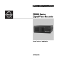
6.1
The display in EBL128
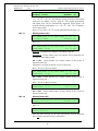
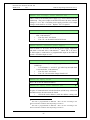
The display (LCD) will in normal operation and in quiescent state
show the following information:
YYYY-MM-DD
*** EBL128 ***
hh:mm [i]
User programmable information text.
Top (first) row19:
YYYY = Year, e.g. 2005
MM = Month, e.g. 02 (=February)
DD = Day, e.g. 28
NOTE! The way the date is
presented can be different
for different languages, e.g.:
DD-MM-YYYY.
hh = hours, e.g. 21
mm = minutes, e.g. 45
[i] = Will only be shown in case of one or more Technical Warnings
in the system.
Bottom (second) row:
The information on the bottom row (40 characters) can be created via
EBLWin, i.e. it is user definable.
6.1.1
LCD backlight
When the information above is shown in the LCD, the backlight is
OFF.
As soon as any other information (see below) is shown in the LCD,
the backlight is turned ON.
In order to reduce the current consumption, the LCD backlight will be
turned OFF if the c.i.e. is powered only by the second power source,
i.e. the battery.20
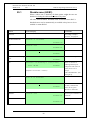
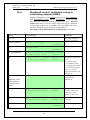
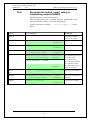
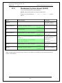
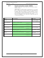
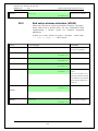
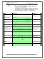
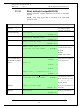
6.1.2
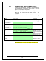
The LCD information priority order
The different type of alarms, faults, etc. listed below are described in
other parts of this document.
19
The information on the top row (40 characters) is included in the text file
downloaded in EBL128, i.e. the information could be different than the one
showed above.
20
In the Australian and New Zealand conventions, the LCD backlight will
not be turned OFF even if the c.i.e. is powered only by the second power
source.
21
Panasonic Eco Solutions Nordic AB
MEW01741
Rev: -
EBL128 Operating Instructions V2.1.x
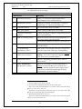
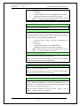
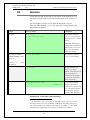
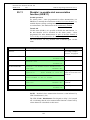
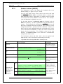
The priority order is shown in the following table:
Priority
1
2
3
4
5
6
7
8
9
10
11
12
13
14
Event
Fire alarms (see below)
Quiet alarm
Co-incidence alarm
Delayed alarm
Pre-warning
Test mode alarm
AAF alarm21
Evacuate information22
New Zealand convention only:
Routing equipment left isolated
Fault (not acknowledged)
Disablement
Zones in "Test mode"
Interlocking input / output active
Information in normal operation in quiescent state
NOTE! Fire alarms are:
Fire alarm
Heavy smoke/heat alarm
Alert Annunciation (AA) alarm
Key cabinet alarm
Acknowledged alarm (New Zealand only)
Isolated alarm (New Zealand only)
The different type of events and the menu system are described in
other parts of this document. Regarding "priority 14", see page 21.
NOTE!
When "More…" is shown, it is possible to scroll between the items
with "↓" and "↑".
21
The AAF function is used in conjunction with an AAF Control, which is
available on the Australian market only.
22
Only valid for Belgian, British Standard, Hungarian, Spanish and
Ukrainian conventions.
22
Panasonic Eco Solutions Nordic AB
MEW01741
Rev: -
7
EBL128 Operating Instructions V2.1.x
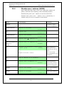
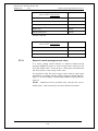
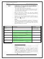
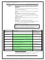
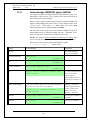
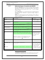
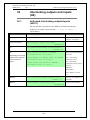
User level, User name & Password
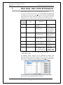
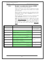
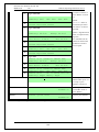
EBL128 has different user levels for different kind of users.
To log on to an EBL128 (version > 2.0) a User name and a Password
are required (see page 85). Ten different User names with individual
Passwords can be used. Each User name is for a specific user level,
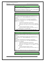
which has access to specific menus according to the following table.
User level
User level name /
Required action /
according
type
equipment
Access to
to EN54-2
1
-
2A
-
No. (Hole in the
Alarms queued
Plexiglas.)
button.
Fire brigade key. (To
Like 1 + Silence
open the door.)
buzzer, Silence
alarm devices &
Reset buttons.
2B
Information only
Like 2A + log on as
Like 2A + keypad.
“Information only”
Menu H4, H6 ,
a)
H9
2C
Building officer
b)
& H10
Like 2A + log on as
Like 2A + keypad.
“Building officer”
H1-H4, H6, H7,
H9 & H10
3A
3B
4
Service personnel
-
Like 2A + log on as
Like 2A + keypad.
“Service personnel”
H1-H10
PC + EBLWin + H/W
SSD & S/W
key
download
PC + EBLWin + H/W
SSD & S/W
key + special password
download + reset
of alarm counter.
a)
b)
Information only, i.e. the faults cannot be acknowledged.
Menu H9/C1 only.
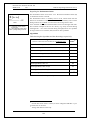
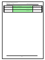
Via EBLWin (menu “System”) are ten different User names with
individual Passwords possible to define in the “User data” dialog box.
They can be used to log on to an EBL128 (version > 2.0) and/or Webserver access. Three User names and Passwords are default:
NOTE! Initials are required in system EBL128 since they will be
used in the event log instead of the User names.
23
Panasonic Eco Solutions Nordic AB
MEW01741
Rev: -
7.1
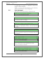
EBL128 Operating Instructions V2.1.x
User level 1
With the door closed, anybody has access to the push button "Alarms
queued" (P1) to scroll / browse through the queued alarms.
7.2
User level 2A
After the door has been opened with the fire brigade key (LED "Door
open" is lit), the user / fire brigade personnel have access to the
following push buttons:
Push
button
Operation/function
P2
Silence the buzzer in the c.i.e.
P3
Silence all alarm devices (sounders).
P4
Reset fire alarms. (see below)
NOTE! Fire alarms are:
Fire alarm (incl. heavy smoke/heat alarm)
Alert Annunciation (AA) alarm
Key cabinet alarm
Co-incidence alarm (if not reset automatically)
Acknowledged alarm (New Zealand only)
Isolated alarm (New Zealand only)
24
Panasonic Eco Solutions Nordic AB
MEW01741
Rev: -
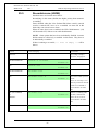
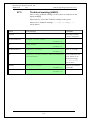
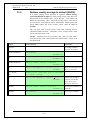
7.3
EBL128 Operating Instructions V2.1.x
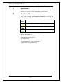
User level 2B
After the door has been opened with the fire brigade key (LED "Door
open" is lit), you have access to level 2A and after log on as
“Information only” (level 2B), access to the following menus:
H4 Present system status
U1 Disablement
U2 Disablement by time channel
U3 Sensor values
U4 Sensors activating SERVICE signal
U5 Technical warning
U6 Event log
U7 Version and alarm counter
H6 Display FAULTS NOTE! Information only!
H9 Interlocking outputs and inputs
C1 Activated interlocking outputs / inputs
H10 Change password (In this case for “Information only”.)
25
Panasonic Eco Solutions Nordic AB
MEW01741
Rev: -
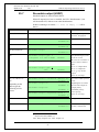
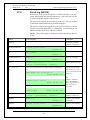
7.4
EBL128 Operating Instructions V2.1.x
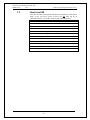
User level 2C
After the door has been opened with the fire brigade key (LED "Door
open" is lit), you have access to level 2A and after log on as “Building
officer” (level 2C), access to the following menus:
H1 Perform monthly test
H2 Disable or re-enable
B1 Disable Zone
B2 Disable zone-address
B3 Disable output
B4 Disable all control, ventilation, exting or interlocking outputs
B5 Re-enable zone
B6 Re-enable zone-address
B7 Re-enable output
B8 Re-enable all control, ventilation, exting or interlocking
outputs
B9 Disable / re-enable alarm devices
B10 Disable / re-enable outputs for routing equipment
B11 Disable / re-enable alert annunciation function
H3 Set calendar and clock
H4 Present system status
U1 Disablement
U2 Disablement by time channel
U3 Sensor values
U4 Sensors activating SERVICE signal
U5 Technical warning
U6 Event log
U7 Version and alarm counter
H6 FAULT Acknowledge
H7 Perform ZONE TEST ("Test mode")
H9 Interlocking outputs and inputs
C1 Activated interlocking outputs / inputs
C2 Activate interlocking output
C3 Reset interlocking output
C4 Disable interlocking output
C5 Re-enable interlocking output
H10 Change password (In this case for “Building officer”.)
26
Panasonic Eco Solutions Nordic AB
MEW01741
Rev: -
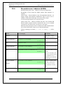
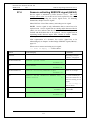
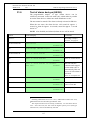
7.5
EBL128 Operating Instructions V2.1.x
User level 3A
After the door has been opened with the fire brigade key (LED "Door
open" is lit), the service / maintenance personnel have access to
level 2A and after log on as “Service personnel” (level 3A), access to
all menus, i.e. like level 2C and also to the following menus:
Same menus as in access level 2C plus the following:
H5 Service
A1 Calibration of supervised outputs
A2 Sensitive fault detection mode
A3 Service mode for COM-loop
A4 Display current consumption in unit
A5 Display current consumption on COM-loop
A6 Display statistics for COM-loop
A7 Activate address setting mode for DU
A8 Setup wireless detectors
A9 End setup wireless detectors
A10 Show information about site specific data
H8 Maintenance
S1 Disconnect / Re-connect COM-loop
S2 Disconnect / Re-connect zone line input
S3 Disconnect / Re-connect addressable zone interface input
S4 Acknowledge SERVICE signal
S5 Restore weekly average to default
S6 Test of alarm devices
S7 Safe shut down of control unit
S8 Activate zone/address in alarm mode
S9 Activate output
S10 Reset activated output
H10 Change password (In this case for “Service personnel”.)
7.6
Access level 3B
Used by Service / maintenance / commissioning engineers when a PC
(i.e. EBLWin) is to be connected to EBL128 for backup (upload),
download of site specific data (SSD) and/or download of software.
An EBLWin key in the PC is required.
27
Panasonic Eco Solutions Nordic AB
MEW01741
Rev: -
7.7
EBL128 Operating Instructions V2.1.x
Access level 4
Used by manufacturer or by personnel authorised by the manufacturer
for re-initialisation (reset) of the alarm counter, change software
configurations, on-line status checking, etc. A special password is
required.
28
Panasonic Eco Solutions Nordic AB
MEW01741
Rev: -
8
EBL128 Operating Instructions V2.1.x
Silence Alarm devices
In EBL128, on the FBP, there is a push button "Silence Alarm
devices" (P3).
If the push button "Silence Alarm devices" is pressed during a prewarning, a fire alarm23 or a Co-incidence alarm, the following will
happen:
LEDs "Fire" (L1) and "Alarms queued" (L2)24 continue to be
blinking (0.4 / 0.4).
Activated outputs25, programmed for sounders (type Alarm
devices), will be silenced.
In case of a new alarm, or if the push button "Silence Alarm devices"
is pressed again, the sounders will automatically sound again.
NOTE! This is also valid for Pre-warning and Co-incidence alarm.
In EBLWin, the option Button "Silence alarm devices" disables alarm
devices can be selected.
In this case the button "Silence alarm devices" (P3) will have the same
function as in the menu H2/B9, see page 100. See also chapter
"Disable / Re-enable alarm devices", page 32.
In the Australian and New Zealand conventions only, the "FIRE"
LEDs will indicate steady instead of blinking when the alarm devices
are disabled.
23
In the New Zealand convention "Acknowledged alarm" (ACK) as well.
When more than one fire alarm is activated.
25
Including Addressable siren 3377 / 4477, Addressable sounder base 3379,
Addressable beacon 4380 and Light indicator 4383.
24
29
Panasonic Eco Solutions Nordic AB
MEW01741
Rev: -
8.1
EBL128 Operating Instructions V2.1.x
Silence alarm devices (inside switch)
NOTE! The functions in this chapter are valid for the New Zealand
convention only.
The button "Silence alarm devices" (P3) is called the "inside switch"
and has the following function:
The inside switch toggles between two states.
Alarm devices disabled
All programmable outputs of type "Alarm devices" are
disabled, i.e. they cannot be activated.
Alarm devices not disabled
All programmable outputs of type "Alarm devices" enabled,
i.e. they can be activated.
If the inside switch is in its disabled state when the c.i.e. door is being
closed the buzzer will beep once and the message "Silence switch
left active" will be shown in the LCD. For priority order see
chapter "The display in EBL128", page 21.
NOTE! The inside switch has no function if the outside switch (see
below) is activated (ON).
8.2
New Zealand FB Silence switch (outside
switch)
NOTE! The functions in this chapter are valid for the New Zealand
convention only.
The "New Zealand FB Silence switch" is called the "outside switch"
since it is placed outside the c.i.e. The outside switch is a key switch
and connected to a programmable input with the trigger condition
"New Zealand FB Silence switch".
The outside switch can be in two states.
The outside switch is turned ON (i.e. from not activated to activated
state).
All programmable outputs of type "Alarm devices" are
disabled, i.e. they cannot be activated. The "inside switch"
(see above) has no function.
LEDs "Fire" (on the front) changes from blinking to steady
(continuous).26
The c.i.e. built-in buzzer is disabled.
A fault is generated27:
active".
26
"FAULT: FB Silence switch
This is valid also if the fire alarm is activated after the outside switch is
turned ON.
30
Panasonic Eco Solutions Nordic AB
MEW01741
Rev: -
EBL128 Operating Instructions V2.1.x
The outside switch is turned OFF (i.e. from activated to not
activated state).
The fault "FAULT: FB Silence switch active" will be
28
Serviced.
Any alarm point / zone in fire alarm state will automatically be
disabled / isolated. (I.e. it has to be re-enabled via menu
H2/B5-B6.)
Any alarm point / zone in fire alarm state will automatically
change state to "Isolated alarm" and in the fire alarm list
(presented in the LCD) will "ALM" be changed to "ISO".
An example:
ISO ZONE-ADDR 12-46 LAST ZONE 12 No. 01
This is a user defined alarm text.
The c.i.e. built-in buzzer is re-enabled.
27
28
Always latched, regardless of if faults are programmed to be not latched.
Since this fault is always latched, it has to be acknowledged via menu H6.
31
Panasonic Eco Solutions Nordic AB
MEW01741
Rev: -
9
EBL128 Operating Instructions V2.1.x
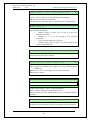
Disable / Re-enable alarm devices
All outputs25 programmed for sounders (type Alarm devices) can via
menu H2/B9 be collectively disabled. This is indicated by LED
"Disablements" (L8) and LED Fault / Disablements "Alarm devices"
(L13) steady (continuous).
NOTE! They will remain disabled until they are re-enabled again via
menu H2/B9.
32
Panasonic Eco Solutions Nordic AB
MEW01741
Rev: -
10
EBL128 Operating Instructions V2.1.x
"Silence buzzer"
The EBL128 built-in buzzer will sound for:
pre-warning (0.8 / 5 sec.)
co-incidence alarm: When only one zone / address (alarm point)
is in alarm status (0.8 / 5 sec.)
fire alarm and acknowledged alarm29 (0.4 / 0.4 sec.)
fault (continuous)
activated interlocking input (0.8 / 0.8 sec.), if this option is
selected via EBLWin.
quiet alarm (0.8 / 5 sec.)
delayed alarm
Press "Silence buzzer" (P2) to silence the buzzer.
In case of a new alarm or if the push button "Silence buzzer" is
pressed again, the buzzer will automatically sound again.30
NOTE! This is also valid for pre-warning, co-incidence alarm, etc.
Silence buzzer by open door
In EBLWin, the function "Silence Buzzer by Door Switch" can be
selected. The buzzer will then be turned off as long as the EBL128
door is open. (This function is a violation to the EN54-2 standard.)
Valid for the New Zealand convention only:
Silence buzzer by the "outside switch"
When the New Zealand FB Silence switch (outside switch, see page
30) is turned ON (i.e. from not activated to activated state) the buzzer
is silenced until the outside switch is turned OFF.
10.1
Buzzer
If there is a fault or disablement when the door to EBL128 is being
closed, the EBL128 built-in buzzer will give a 2 seconds beep directly
after the door is closed. One fault message or disablement will be
shown in the LCD but more faults and/or disablements will be
indicated by the word "more".
NOTE! In the New Zealand convention, if any of the outputs for
routing equipment ("Fire brigade tx" and "Fault tx") or outputs for
alarm devices is disabled when the door to EBL128 is being closed,
the EBL128 built-in buzzer will beep continuously directly after the
door is closed. "Alarm routing equipment left isolated",
"Fault routing equipment left isolated" and "Silence
switch left active" respectively, will be shown in the LCD.
This information has higher priority than the normal fault messages
and disablements.
29
30
Acknowledged alarm in the New Zealand convention only.
Not valid if the buzzer is silenced by the open door.
33
Panasonic Eco Solutions Nordic AB
MEW01741
Rev: -
11
EBL128 Operating Instructions V2.1.x
Disable / Re-enable all control,
extinguishing, ventilation and
interlocking outputs
All control outputs programmed as type:
Control (general)
Fire ventilation
Extinguishing system
Interlocking
… can via menu H2/B4 be collectively disabled, type by type. This is
indicated by the LED "Disablements" (L8).
They will remain disabled until they are re-enabled again via menu
H2/B8.
See also chapters "Disable all control, ventilation, exting or
interlocking outputs (H2/B4)", page 94 and "Re-enable all control,
ventil, exting or interlocking outputs (H2/B8)", page 99.
34
Panasonic Eco Solutions Nordic AB
MEW01741
Rev: -
12
EBL128 Operating Instructions V2.1.x
Evacuate, Alert Annunciation
Acknowledge and Disable
These functions are only valid in some conventions.
A front with the push button (P5) is required.
See also chapters "Control & Indicating Equipment", page 14 and
"LED indicators and push buttons", page 16.
12.1
Evacuate
When the green push button "Evacuate" (P5) is pressed, all outputs
programmed for sounders (type Alarm devices)25 will be collectively
turned ON steady (continuous). This is indicated by the following
information in the EBL128 display:
Evacuate in progress
The sounders will remain ON until they are turned OFF by pressing
the push button "Evacuate" (P5) again.
NOTE! The alarm devices (sounders) will in this case be activated
steady (continuous) irrespective of the fact that the outputs can be set
to something else for fire alarm (e.g. intermittent).
12.2
Alert Annunciation Acknowledge
The green button "Alert Annunciation Acknowledge" (P5) has the
same function as the Acknowledge button on an AA unit 1735 / 1736.
12.3
Disable
When the yellow push button "Disable" (P5) is pressed, all zones in
fire condition will be disabled.
35
Panasonic Eco Solutions Nordic AB
MEW01741
Rev: -
13
EBL128 Operating Instructions V2.1.x
German functions / units
It is possible to connect some units that are required in Germany, e.g.
Feuerwehr BedienFeld – FBF (German external Fire Brigade Panel)
and Feuerwehr AnzeigeTableau – FAT (German Fire Brigade
Indicator Panel).
When the German panels are connected the standard Display units –
External Fire Brigade Panel, Alert Annunciation Unit and External
Presentation Unit – cannot be connected and vice versa.
A German front is also required – with German texts and with
different function on two of the LEDs (i.e. L10 and L12).
13.1
Push-button "ÜE prüfen"
When push-button "ÜE prüfen" on "Feuerwehr-Bedienfeld" (FBF) is
pressed, the output to fire alarm routing equipment will be activated, if
it is not disabled.
The output will be activated as long as the push-button "ÜE prüfen" is
pressed, i.e. when the push-button is released the output will be deactivated. The push-button "ÜE prüfen" is non-locking.
During the test with push-button "ÜE prüfen", the c.i.e. shall send a
signal to the FBF in order to indicate "ÜE ausgelöst" on the FBF.
Since the c.i.e. supports fire alarm routing equipment (ÜEs) with or
without feedback signal, there are two cases:
1) Without feedback signal: In this case the c.i.e. activates a signal to
the FBF as long as the output to the fire alarm routing equipment is
activated.
2) With feedback signal: In this case the c.i.e. activates a signal to the
FBF if the output to the fire alarm routing equipment is activated and
the c.i.e. receives a feedback signal from the fire alarm routing
equipment. The signal to the FBF is latched as long as the output to
the fire alarm routing equipment is activated.
13.2
Button "Brandfall Steuerungen ab"
The button "Brandfall Steuerungen ab" on "Feuerwehr-Bedienfeld"
(FBF) will disable the three output types Control, Fire ventilation
and Extinguishing. All these type of outputs are nominated as output
G in DIN EN 54-1.
It is not possible to disable the outputs, with the button "Brandfall
Steuerungen ab", when c.i.e. is in fire alarm condition.
When the outputs are disabled from the FBF (via button "Brandfall
Steuerungen ab") it is not possible to re-enable them in the c.i.e. via
menu H2/B8.
36
Panasonic Eco Solutions Nordic AB
MEW01741
Rev: -
EBL128 Operating Instructions V2.1.x
When the outputs are disabled in the c.i.e. via menu H2/B4 it is not
possible to re-enable them from the FBF (via button "Brandfall
Steuerungen ab").
13.3
Indication "Brandfall Steuerungen ab"
The indication "Brandfall Steuerungen ab" on "FeuerwehrBedienfeld" (FBF) is turned on if any of the three output types
Control, Fire ventilation and Extinguishing is disabled.
13.4
Button "Akustische Signale ab"
The button "Akustische Signale ab" on "Feuerwehr-Bedienfeld" (FBF)
has the same function as the menu "Disable alarm devices" (H2/B9) in
the c.i.e.
If pushed during fire alarm condition the button "Akustische Signale
ab" will also silence the buzzer in the c.i.e.
When the outputs are disabled from the FBF (via button "Akustische
Signale ab") it is not possible to re-enable them from the CIE.
However, during fire alarm condition and if the outputs to fire alarm
devices (outputs C) have been disabled from the c.i.e. it is possible to
re-enable them from the FBF.
13.5
Indication "Akustische Signale ab"
The indication "Akustische Signale ab" on "Feuerwehr-Bedienfeld"
(FBF) is turned on when the outputs to alarm devices are disabled.
13.5.1
Indication in button "Akustische Signale ab"
(Switch "1" on the DIP switch in FBF (2003) shall be in position ON.)
The LED in button "Akustische Signale ab" follow the indication
"Akustische Signale ab" on "Feuerwehr-Bedienfeld" (FBF) i.e. LED
turned on means that the outputs to alarm devices are disabled.
13.6
The buzzer in the c.i.e.
Even if the outputs to alarm devices are disabled, the buzzer in the
c.i.e. will re-sound in case of a new alarm. It is possible to silence the
buzzer by pressing the button "Akustische Signale ab" (outputs to
alarm devices will be re-enabled) and immediately press the button
"Akustische Signale ab" again (outputs to alarm devices will be
disabled again). In this case there is a risk that the alarm devices
will sound for a short while.
13.7
Button "ÜE ab"
The button "ÜE ab" on "Feuerwehr-Bedienfeld" (FBF) will disable all
the outputs of type Routing equipment, nominated as output E in DIN
EN 54-1.
37
Panasonic Eco Solutions Nordic AB
MEW01741
Rev: -
EBL128 Operating Instructions V2.1.x
NOTE! It is not possible to disable the outputs with the button "ÜE
ab" when the c.i.e. is in fire alarm condition.
13.8
Indication "ÜE ab"
The indication "ÜE ab" on "Feuerwehr-Bedienfeld" (FBF) is turned
on when the outputs of type Routing equipment are disabled.
When the outputs are disabled from the FBF (via button "ÜE ab") it is
not possible to re-enable them via menu H2/B9 in the c.i.e.
When the outputs are disabled via menu H2/B9 in the c.i.e. it is not
possible to re-enable them from the FBF (via button "ÜE ab").
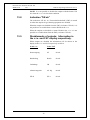
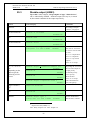
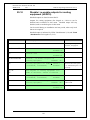
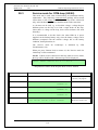
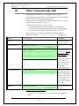
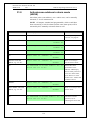
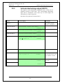
13.9
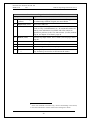
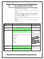
Disablements of outputs; Information in
the c.i.e. and FAT display respectively.
When outputs are disabled the information will be shown in the
display in the c.i.e. and FAT respectively as follow:
In the c.i.e.
In the FAT
Steuerausgang
ST
Absch.
Rauchabzug
Rauch
Absch.
Löshanlage
LB
Absch.
Alarmierungseinr.
Ak. Sig
Absch.
ÜE ab
ÜE-1
Absch.
38
Panasonic Eco Solutions Nordic AB
MEW01741
Rev: -
14
EBL128 Operating Instructions V2.1.x
Door open
A special key is used to open the EBL128 door to get access to the
front, see chapter "User level, User name & Password", page 23. The
same type of key is also used to open the ext. FBP door / the key
switch. Door open31 is indicated by LED "Door open" (L10).
14.1
LED "Door open"
Valid for the door in EBL128 or an external FBP connected to
EBL128: Door open in EBL128 is indicated by LED "Door open" in
EBL128. Door open in an ext. FBP is indicated by LED "Door open"
in EBL128.
14.2
Outputs for routing equipment (Fire
brigade tx and Fault tx)
In EBLWin the following can be programmed:
None: The output(s) for routing equipment (Fire brigade and fault tx)
will not be disabled by any open door.
Any Control Unit Door: Door open in EBL128 will disable the
output(s) for routing equipment (Fire brigade and fault tx).
Any Door: Door open in EBL128 and/or Ext. Fire Brigade Panel will
disable the output(s) for routing equipment (Fire brigade and fault
tx).
Disabled outputs for routing equipment are indicated by the LED
"Disablements" (L8) and "Fault / Disablements Fire brigade tx"
(L15) and listed in menu H4/U1.
In the display is shown:
All outputs to fire alarm routing equip.
disabled by open door
14.3
Silence buzzer
In EBLWin the following can be programmed:
The buzzer in the control unit will be turned off as long as the
EBL128 door is open.
(This function is a violation to the EN54-2 standard.)
31
In the ext. FBP 1828: when the key is turned to the "position open /
access".
39
Panasonic Eco Solutions Nordic AB
MEW01741
Rev: -
EBL128 Operating Instructions V2.1.x
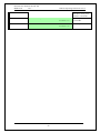
15
Technical address / Presentation
number
15.1
Technical address for COM loop units
The technical address in EBL128 is used when programming (via
EBLWin) all units connected to the COM loop.
The technical address is also used to identify which unit has generated
a fault.
The technical address is equal to the address that is set in each unit
connected to the COM loop with the Address setting tool 3314/4414.
Addresses 001 – 255 can be set (not 000).
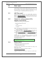
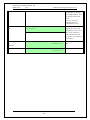
15.2
Presentation number
For each fire alarm point / zone line input, a presentation number,
NN-NN, has to be programmed. The presentation number is shown in
the display in EBL128 and in Ext. FBP 1826 / 1828, Alert
Annunciation unit 1735 / 1736 and Ext. Presentation unit 1728, to
identify the point / zone generating a fire alarm. It is also used to
disable / re-enable fire alarm points / zones and in control conditions /
expressions to activate the programmable outputs.
Together with the presentation number, an alarm text with up to 40
alphanumeric characters can be displayed (if programmed via
EBLWin).
NN – NN
00 – 99
01 – 99 = The Address within the zone.
00 = Zone number only will be displayed.
E.g. for one or more conventional detectors
connected to a MIO (3361) or a zone line input
(4580)
01 – 99 = Zone number
40
Panasonic Eco Solutions Nordic AB
MEW01741
Rev: -
16
EBL128 Operating Instructions V2.1.x
Alarm types
In case of a fire, analog detectors (sensors), conventional smoke
and/or heat detectors, manual call points and programmable inputs can
generate fire alarm.32 If somebody illegally breaks into a key cabinet,
this will also generate a "fire alarm" (a Key cabinet alarm).33
A fire alarm could be an Alert Annunciation alarm, i.e. the
activation of the routing equipment (fire brigade tx) is delayed during
an acknowledgement time and an investigation time respectively.
In the Australian convention only, an Alarm Acknowledgement
Facility function can be used. During the Acknowledgement Period
and the Investigation Period respectively, there will be an indication in
the c.i.e. display.
The analog detectors can also generate other type of "alarms", i.e.
Pre-warning, Heavy smoke alarm / Heavy heat alarm and a twounit / -zone dependent alarm point / zone can generate a Co-incidence
alarm.34 Quiet alarm is used for fan control.
EBL128 can handle and present up to 256 fire alarms (alarm points
and/or zones). Zone numbers 01-99 can be used and in each zone the
alarm point (address) numbers 01-99 can be used. The fire alarms
will be shown in the EBL128 display and in Ext. FBP 1826 / 1828,
Alert Annunciation unit 1735 / 1736 and Ext. Presentation unit 1728.
Regarding the different alarm types, etc., see the following chapters.
16.1
Pre-warning
An analog detector will generate a pre-warning for a lower alarm level
than the fire alarm level.35 Pre-warning can be used when an early
alarm and/or an early action is required (e.g. a "soft" computer shut
down). Normal alarm devices, routing equipment, etc. will not be
activated.
In case of a pre-warning, the following will happen:
The buzzer in EBL128 sounds 0.8 sec. each 5th sec. (0.8 / 5
sec.).
Outputs programmed for pre-warning are activated.36
On the first row in the EBL128 display, the presentation
number (zone-address) is shown (for the first pre-warning).
32
In the New Zealand convention only, a Fire alarm (ALM) can be
"changed" to an Acknowledged alarm (ACK) or an Isolated alarm (ISO).
33
This is done via a programmable input.
34
This function is normally used for smoke detectors only.
35
See EBL128 Planning Instructions. Any programmable input can also be
used to activate a pre-warning.
36
Outputs programmed for General pre-warning and outputs programmed
for the activated pre-warning(s).
41
Panasonic Eco Solutions Nordic AB
MEW01741
Rev: -
EBL128 Operating Instructions V2.1.x
On the second row, an alarm text (= the fire alarm text) will
be shown (if programmed).
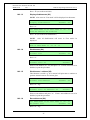
Example; pre-warning zone 12, address 45 (within zone 12):
Pre-warning detector 12-45
(alarm text)
Example; pre-warning zone 12:
Pre-warning zone 12
(alarm text)
LEDs "Alarms queued" (L2) blinking are indicating more than
one pre-warning and they will be automatically scrolled (each
5th second).
Pre-warning is automatically reset see chapter "Alarm reset", page 54.
16.2
Fire alarm
256 alarms (points or zones) can be presented in the EBL128 display.
See also chapter "The display in EBL128", page 21. According to the
EN54-2 standard, in case of a fire alarm, the following will happen:
The buzzer in EBL128 sounds 0.4 sec. each 0.8th sec. (0.4 /
0.4 sec.).
LEDs "Fire" (L1) are blinking (0.4 / 0.4 sec.).
Output for routing equipment (Fire brigade tx) is activated.
See also NOTE! below.
Programmable outputs for fire alarm are activated.37
In the EBL128 display (and ext. FBP display), the fire
alarm(s) will be presented. See below.
NOTE! Normally the c.i.e. relay output "R0" is used as the output for
Routing equipment (Fire brigade tx). The output will then be
activated for fire alarm from any alarm point or zone line input.
If the fire alarm routing equipment has provision for transmission of
several fire alarm signals and the alarm receiver has provision for
reception of several fire alarm signals, the alarm receiver can take
different actions depending on if it is a fire alarm type A or B.
If a fire alarm type B is received, it will indicate that only one analog
addressable smoke, heat or multi detector is activated, which could be
a nuisance alarm.
If a fire alarm type A is received, it is probably a real fire since fire
alarm is then activated from:
Two or more analog addressable smoke, heat or multi
detectors.
37
Programmable outputs for "General fire alarm" and for the activated fire
alarm(s).
42
Panasonic Eco Solutions Nordic AB
MEW01741
Rev: -
EBL128 Operating Instructions V2.1.x
Any manual call point
Any zone line input
Any programmable input with the trigger condition "General
Fire"
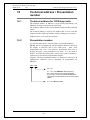
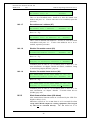
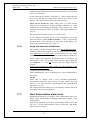
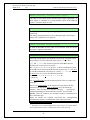
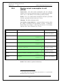
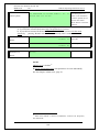
Fire alarm presentation in the EBL128 display38:
B
123456 789012345678901234567890 1234567890
C
A
D
A: Field for the first alarm point or zone in alarm.
By scrolling each alarm will be shown in this field.
B: Field for the most recent (last) zone in alarm.
C: Field for total number of zones in alarm.
D: Field for alarm text. (User definable.)
Comments to the different fields38:
The information in the field A:
NNN ZONE-ADDR ZZ-AA
or
NNN ZONE ZZ
NNN = a serial number for the displayed alarm, i.e. 001 for the first
activated alarm (ZZ-AA), 002 for the second alarm and so on.
ZZ = zone number 01 – 99. AA = address 01 – 99
The information in the field B:
LAST ZONE zz
zz = zone number 01 – 99 for the most recent zone in alarm.
Displayed also if only one alarm point is in alarm.
The information in the field C:
No. nn
nn = 01 – 99 = the total number of zones (not alarm points) in alarm.
The information in the field D:
A user definable alarm text (max. 40 characters) for the alarm
displayed in the field "A".
Some Fire alarm examples:
One alarm point (e.g. detector 12-45)
38
In the German (VdS) convention and the New Zealand convention the
presentation is different and described in separate documents.
43
Panasonic Eco Solutions Nordic AB
MEW01741
Rev: -
EBL128 Operating Instructions V2.1.x
001 ZONE-ADDR 12-45 LAST ZONE 12
"Alarm text for 12-45"
No. 01
One zone (e.g. zone 14; a conventional zone line input)
001 ZONE 14
LAST ZONE 14
"Alarm text for zone 14"
No. 01
More than one alarm point in one zone (e.g. detectors 12-45 & -46)
001 ZONE-ADDR 12-45 LAST ZONE 12
"Alarm text for 12-45"
No. 01
The LEDs "Alarms queued" (L2) are indicating that more than one
alarm point is in alarm. Press the button "Alarms queued" (P1) to see
the other alarm:
002 ZONE-ADDR 12-46 LAST ZONE 12
"Alarm text for 12-46"
No. 01
One alarm point in two zones (e.g. detectors 12-45 & 13-02)
001 ZONE-ADDR 12-45 LAST ZONE 13
"Alarm text for 12-45"
No. 02
The LEDs "Alarms queued" (L2) are indicating that more than one
alarm point is in alarm. Press the button "Alarms queued" (P1) to see
the other alarm:
002 ZONE-ADDR 13-02 LAST ZONE 13
"Alarm text for 13-02"
No. 02
More than one alarm point / zone
LEDs "Alarms queued" (L2) are blinking (0.4 / 0.4 sec.), indicating
more than one fire alarm.39 To scroll through the alarms, use the push
button "Scroll" (P1). The fire alarms are stored in a circular buffer
and when scrolling from the last to the first alarm, the LEDs "Alarms
queued" will be turned off for approx. three seconds.
When the "Scroll" button has been used the first alarm will be
automatically displayed again after 20 seconds.
If an ext. FBP 1826 with a built-in printer is connected, the printer
will print each fire alarm40, e.g.:
*** Fire Alarm ***
ZONE-ADDR: 12-45 Time HH.MM
Alarm text for 12-45
39
Date MM-DD
Up to 256 alarms can be presented in the display. Alarm = ZONE and/or
ZONE-ADDRESS.
40
The alarms will be printed like they are presented in the display, i.e. as an
alarm point (ZZ-AA) or a zone (ZZ) and alarm text if programmed.
44
Panasonic Eco Solutions Nordic AB
MEW01741
Rev: -
EBL128 Operating Instructions V2.1.x
or
*** Fire Alarm ***
ZONE: 14
Time HH.MM
Alarm text for zone 14
Date MM-DD
Reset of the fire alarms, see chapter "Alarm reset", page 54.
NOTE!
1. The fire alarm presentation in the EBL128 display is for the
German (VdS) convention only, different than described above.
The serial number for the displayed alarm is deleted and the different
fields on the top row are separated by black squares as follows (an
example):
BER-ADR 12-45 █ LETZTER BER 12 █
"Alarm text for 12-45"
Nr.01
2. The fire alarm presentation in the EBL128 display is for the New
Zealand convention only, different than described above.
The serial number for the displayed alarm is replaced with the
information "ALM" as follows (an example):
ALM ZONE-ADDR 13-02 LAST ZONE 13
"Alarm text for 13-02"
No. 02
If the fire alarm is acknowledged (see page 57), "ALM" will be
replaced with "ACK".
If the fire alarm or the acknowledged alarm is isolated (see page 57),
"ALM" will be replaced with "ISO".
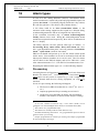
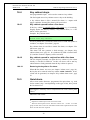
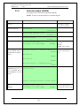
16.2.1
Fire alarm menu (X1-X9)
During the fire alarm presentation, a special fire alarm menu can be
used. (If this menu / option is excluded (via EBLWin), it is a violation
to the EN54-2 standard).
Fire alarms can be displayed via this menu but it can also be used to
display faults and disablements in the system.
Alarm points, zones, control outputs and alarm devices can also be
disabled / re-enabled via this menu.
No User name and Password are required.
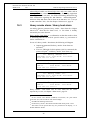
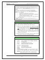
During the fire alarm presentation press button "Access" 41 and the
alarm text will be replaced with the following:
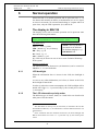
41
Access code is not required.
45
Panasonic Eco Solutions Nordic AB
MEW01741
Rev: -
EBL128 Operating Instructions V2.1.x
001 ZONE-ADDR 12-45 LAST ZONE 12 No. 01
Display alarms
ACCEPT? X1
"A", "", "", "", "" and "Return" can be used like in the normal
menu tree, see chapter "Access", page 85. The original presentation
(the alarm text) will be automatically displayed again approx. 20
seconds after the push buttons "A", "", "", "", "" or "Return"
are no longer used.
Press "A" or scroll ("", "") to the wanted menu and press "A".
16.2.1.1
Display alarms (X1)
001 ZONE-ADDR 12-45 LAST ZONE 12 No. 01
Display alarms
ACCEPT? X1
Press "A"
001 ZONE-ADDR 12-45 LAST ZONE 12 No. 01
ZONE-ADDR: 12-45
001 of 003
First row: Explanations in chapter "Fire alarm", page 42.
Second row: All fire alarms (up to 256 alarms) will be displayed one
at a time in zone-address order.
001 of 003 = alarm number one of three alarms in the system is
displayed to the left.
One alarm is an alarm point (ZZ-AA) or a zone (ZZ).
Press "" (to see the next alarm).
001 ZONE-ADDR 12-45 LAST ZONE 12 No. 01
ZONE-ADDR: 12-46
002 of 003
002 of 003 = alarm number two of three alarms in the system is
displayed to the left.
Press "" (to see the next alarm).
001 ZONE-ADDR 12-45 LAST ZONE 12 No. 01
ZONE-ADDR: 12-47
003 of 003
003 of 003 = alarm number three of three alarms in the system is
displayed to the left.
16.2.1.2
Display faults (X2)
001 ZONE-ADDR 12-45 LAST ZONE 12 No. 01
Display faults
ACCEPT? X2
Press "A"
001 ZONE-ADDR 12-45 LAST ZONE 12
FAULT: Battery
No. 01
Only the fault message for the fault respectively, will be displayed
here, not date, time and "status" information.
46
Panasonic Eco Solutions Nordic AB
MEW01741
Rev: -
EBL128 Operating Instructions V2.1.x
Press "" (to see the next fault).
16.2.1.3
Display disablements (X3)
NOTE! Also zones in "Test mode" will be displayed via this menu.
001 ZONE-ADDR 12-45 LAST ZONE 12 No. 01
Display disablements
ACCEPT? X3
Press "A"
001 ZONE-ADDR 12-45 LAST ZONE 12
Zone XX address XX disabled
No. 01
Press "" (to see the next disablement).
NOTE! After all disablements will zones in "Test mode" be
displayed.
001 ZONE-ADDR 12-45 LAST ZONE 12
Zone in TEST MODE: 01
16.2.1.4
02
03
No. 01
04
Disable zone (X4)
001 ZONE-ADDR 12-45 LAST ZONE 12 No. 01
Disable zone
ACCEPT? X4
Press "A"
001 ZONE-ADDR 12-45 LAST ZONE 12 No. 01
Disable zone: 00
ACCEPT?
Write a zone number (01 – 99) and press "A". If more zones are to be
disabled, repeat the procedure.
16.2.1.5
Disable zone / address (X5)
This function is useful e.g. for a manual call point not to continue to
generate alarms because of a broken glass.
001 ZONE-ADDR 12-45 LAST ZONE 12 No. 01
Disable zone-address
ACCEPT? X5
Press "A". E.g.:
001 ZONE-ADDR 12-45 LAST ZONE 12 No. 01
Disable zone: 00 Address: 00
ACCEPT?
Write a zone-address and press "A". If more zone-addresses are to be
disabled, repeat the procedure.
16.2.1.6
Re-enable zone (X6)
001 ZONE-ADDR 12-45 LAST ZONE 12 No. 01
Re-enable zone
ACCEPT? X6
Press "A". E.g.:
47
Panasonic Eco Solutions Nordic AB
MEW01741
Rev: -
EBL128 Operating Instructions V2.1.x
001 ZONE-ADDR 12-45 LAST ZONE 12 No. 01
Re-enable zone: ZZ
ACCEPT?
This is a list of disabled zones. Scroll to or write the wanted zone
number and press "A". If more zones are to be re-enabled, repeat the
procedure.
16.2.1.7
Re-enable zone / address (X7)
001 ZONE-ADDR 12-45 LAST ZONE 12 No. 01
Re-enable zone / address
ACCEPT? X7
Press "A". E.g.:
001 ZONE-ADDR 12-45 LAST ZONE 12 No. 01
Re-enable zone: ZZ Address: 00
ACCEPT?
This is a list of disabled zone-addresses. Scroll to or write the wanted
zone-address and press "A". If more zone-addresses are to be reenabled, repeat the procedure.
16.2.1.8
Disable / Re-enable control (X8)
001 ZONE-ADDR 12-45 LAST ZONE 12 No. 01
Disable/Re-enable control
ACCEPT? X8
Press "A". E.g.:
001 ZONE-ADDR 12-45 LAST ZONE 12 No. 01
Dis(=0) or re-en(=1) control? 1 ACCEPT?
To disable, press "0" and "A". (To re-enable, press "1" and "A".). For
more information, see chapter "Disable all control, ventilation, exting
or interlocking outputs (H2/B4)", page 94.
16.2.1.9
Disable / Re-enable alarm devices (X9)
001 ZONE-ADDR 12-45 LAST ZONE 12 No. 01
Disable/Re-enable alarm dev. ACCEPT? X9
Press "A". E.g.:
001 ZONE-ADDR 12-45 LAST ZONE 12 No. 01
Dis(=0) or re-en(=1) alarm dev?1 ACCEPT?
To disable, press "0" and "A". (To re-enable, press "1" and "A".). For
more information, see chapter "Disable / re-enable alarm devices
(H2/B9), page 100.
16.2.2
Alert Annunciation alarm (AA alarm)
Alert Annunciation function turned on is indicated by the LED "Fire
brigade tx delay" (L16).
Indications, actions etc. for an AA alarm is as for a normal fire alarm
except that EBL128 output for routing equipment (Fire brigade
tx) will not be activated directly. The AA alarm has to be
48
Panasonic Eco Solutions Nordic AB
MEW01741
Rev: -
EBL128 Operating Instructions V2.1.x
acknowledged within an acknowledge time and reset within and an
investigation time, otherwise will the output for routing equipment
(Fire brigade tx) be activated. See EBL128 Planning Instructions for
more information regarding the AA function. Acknowledgement42
and reset of the AA alarm can be done on an AA unit 1735 / 1736 (or
an AA controller 1740). See also chapter "Alarm reset", page 54.
16.3
Heavy smoke alarm / Heavy heat alarm
An analog detector generates heavy smoke / heat alarm for a higher
alarm level43 than the fire alarm level, i.e. fire alarm is already
activated by the same detector.
Heavy smoke / heat alarm is a confirmation on that the smoke or heat
is increasing and can be used for special actions, e.g. activation of
smoke ventilation, etc.
In case of a heavy smoke / heat alarm, the following will happen:
Outputs programmed for heavy smoke / heat alarm are
activated.44
If an ext. FBP with a built-in printer (1826) is connected, the
printer will print45 each heavy smoke / heat alarm, e.g.:
*** Heavy smoke ***
ZONE-ADDR: 12-45 Time HH.MM
Alarm text for 12-45
Date MM-DD
or
*** Heavy smoke ***
ZONE: 14
Time HH.MM
Alarm text for zone 12
Date MM-DD
*** Heavy heat ***
ZONE-ADDR: 12-45 Time HH.MM
Alarm text for 12-45
Date MM-DD
or
*** Heavy heat ***
ZONE: 14
Time HH.MM
Alarm text for zone 14
Date MM-DD
Heavy smoke / heat alarm will be reset when the fire alarm
respectively is reset, see chapter "Alarm reset", page 54.
42
In the "Czech" and "Polish" (CNBOP) conventions, the push button
"Evacuate" (P5) can be used for "AA Acknowledge".
43
See EBL128 Planning Instructions.
44
General heavy smoke / heat alarm and individual alarm points / zones.
45
The alarms will be printed like they are presented in the display, i.e. as
ZONE-ADDR or ZONE.
49
Panasonic Eco Solutions Nordic AB
MEW01741
Rev: -
16.4
EBL128 Operating Instructions V2.1.x
Key cabinet alarm
One programmable input46 can be used to connect a key cabinet.
The fire brigade uses a key cabinet to store a key to the building.
A key cabinet alarm is like a normal fire alarm, i.e. outputs with
trigger condition "General fire alarm" will be activated.
16.4.1
Key cabinet opened before a fire alarm
If the key cabinet is opened before a fire alarm (e.g. if somebody
illegally breaks into the key cabinet), a key cabinet alarm, i.e. a "fire
alarm" will be generated.
Example; Key cabinet alarm:
ZONE: KE
Alarm from key cabinet
No. 01
It will be printed like a normal fire alarm if an ext. FBP with printer is
available, see chapter "Fire alarm", page 42.
Key cabinet alarm is reset like a normal fire alarm, see chapter "Fire
alarm reset, page 54.
This alarm will also generate a fault message, see chapter "Key
cabinet alarm reset", page 56. It is indicated by LED "General fault"
(L7) and the "Fault tx" output(s) will be activated.
16.4.2
Key cabinet opened in conjunction with a fire alarm
The fire brigade personnel can open the key cabinet if a fire alarm
already is activated in EBL128 In this case there will be no key
cabinet alarm or fault generated when the key cabinet is opened.
16.4.2.1
Restoring the key after a fire alarm
When all fire alarms are reset (see chapter "Alarm reset", page 54),
the key has to be restored in the key cabinet within 5 minutes. If not,
a fault will be generated, see chapter "Key cabinet alarm reset", page
56.
16.5
Quiet alarm
One or more smoke detectors, programmed for quiet alarm, e.g. used
for fan control (stop / start depending on the type of fan), have passed
the fire alarm level.
Quiet alarm is normally used in conjunction with a Fan control panel
(4593).47
Indications and actions:
46
Input I0 or COM loop I/O unit 3361 can be used.
The Fan control panel can be used for control of 4 + 4 fans. For each
group of four fans is also one I/O Matrix board 4582 required and for each
fan is one I/O unit 3361 required.
47
50
Panasonic Eco Solutions Nordic AB
MEW01741
Rev: -
EBL128 Operating Instructions V2.1.x
LEDs "Fire" (L1) are blinking (0.4 / 0.4 sec.), the buzzer sounds (0.8 /
5 sec.) and there is a Quiet alarm presentation in the display:
Quiet alarm detector ZZ/AA
(user definable text message)
Programmable outputs for quiet alarm are activated, e.g. 3361 outputs
controlling supply air fans and standard fans, i.e. any output with a
control expression containing the trigger conditions "Quiet Alarm
Zone" or "Quiet Alarm Zone Address".
16.6
Co-incidence alarm (two-unit / -zone
dependence)
When only one two-unit dependent alarm point, (i.e. one zone –
address) is in alarm status48 or when only one two-zone dependent
zone is in alarm status49, the buzzer sounds (0.8 / 5 sec.) and there is a
Co-incidence alarm presentation in the display.
Co-incidence alarm detector ZZ/AA
or
Co-incidence alarm zone ZZ
If there are Co-incidence alarms generated in other zones, the LEDs
"Alarms queued" (L2) are blinking and the Co-incidence alarms will
be automatically scrolled (each 5th second).
Co-incidence alarm is automatically reset 5 minutes after the alarm
point / zone is no longer in alarm status or by the Reset button (P4),
see chapter "Alarm reset", page 54.
16.7
Delayed alarm
Delayed alarm is an option that has to be enabled (via EBLWin) for
the alarm point respectively.
The delay time (0-255 sec.) is, for the whole system, set via EBLWin
(System Properties, page 1). The delay time will be added at the end
of the alarm algorithm when a fire alarm normally would have been
activated. For that reason this "extra" delay time should be as short as
possible.
48
If two or more two-unit dependent alarm points (zone - addresses) in the
same zone are in alarm status at the same time, normal fire alarms will be
activated in EBL128. See also EBL128 Planning Instructions.
49
If two or more two-zone dependent zones in the same group are in alarm
status at the same time, normal fire alarms will be activated in EBL128. See
also EBL128 Planning Instructions.
51
Panasonic Eco Solutions Nordic AB
MEW01741
Rev: -
EBL128 Operating Instructions V2.1.x
The Delayed alarm will be activated when the delay time countdown
has started and will be activated until the delay time has run out and a
normal fire alarm is activated. Normal alarm devices, routing
equipment, etc. will not be activated.
In case of a Delayed alarm, the following happens:
The buzzer in EBL128 sounds 0.8 sec. each 5th sec. (0.8 /
5 sec.).
Outputs programmed for delayed alarm are activated.50
On the first row in the EBL128 display, the presentation
number (zone-address) is shown (for the first delayed
alarm).
On the second row, an alarm text (= the fire alarm text)
will be shown (if programmed).
Example:
Delayed alarm detector ZZ/AA
or
Delayed alarm zone ZZ
LEDs "Alarms queued" (L2) blinking are indicating more than
one delayed alarm and they will be automatically scrolled
(each 5th second).
Delayed alarm is automatically reset see chapter "Alarm reset", page
54.
16.8
Alarm Acknowledgement Facility (AAF)
Used on the Australian market only.
One or more Alarm Acknowledgement Facility Controls51 are used in
the system.
During the Acknowledgement Period (10-60 sec.) there is an
indication in the control unit display:
AAF zone zz, activated
During the Investigation Period (0-3 min.) there is an indication in the
c.i.e. display:
AAF zone zz, investigation in progress
50
Outputs programmed for General pre-warning and outputs programmed
for the activated pre-warning(s).
51
The AAF Control is available on the Australian market only.
52
Panasonic Eco Solutions Nordic AB
MEW01741
Rev: -
EBL128 Operating Instructions V2.1.x
See EBL128 Planning Instructions chapter "Alarm Acknowledgement
Facility (AAF)" for more information regarding the AAF function.
53
Panasonic Eco Solutions Nordic AB
MEW01741
Rev: -
EBL128 Operating Instructions V2.1.x
17
Alarm reset
17.1
Pre-warning reset
Pre-warnings are non-latching, i.e. they will be automatically reset
when the alarm point / zone is no longer above pre-warning level.
Outputs activated by pre-warning will be de-activated. (In some cases
after a programmable delay time.)
17.2
Fire alarm reset
In the New Zealand convention fire alarms = normal fire alarms
(ALM), acknowledged alarms (ACK) and isolated alarms (ISO).
NOTE! The detectors having activated the fire alarms shall, after
reset, be inspected, tested and replaced when required.
One of the following alarm reset alternatives is valid. This is selected
via EBLWin. "All" is default.
17.2.1
All
All activated fire alarms (alarm points / zones) will be reset by
pressing "Reset" (P4) once. (This is in accordance with the EN54-2
standard).
NOTE! The push button has to be pressed for min. 0.5 sec.
When all fire alarms are reset, LEDs "Fire" (L1) and "Alarms
queued" (L2) are turned off. If there are other conditions (e.g. a fault
condition) the corresponding information will be shown (e.g. a fault
message), for the priority order see chapter "The display in EBL128",
page 21.
All outputs (for fire alarm) are reset, i.e. de-activated.
If a key cabinet is installed, the key (to the building) has to be put
back into the key cabinet within 5 minutes. If not, a fault will be
generated and a fault message will be shown in the display, see
chapter "Key cabinet alarm reset”, page 56.
NOTE!
When "Single" or "Single with automatic disablement" is used, all
alarms can be reset by pressing "Reset" (P4) and approx. 0.1 sec. later
also press "A" (in the keypad) and hold them pressed for > 0.5 sec.
17.2.2
Single
Each fire alarm (alarm point / zone) has to be reset one by one.
NOTE! This function is available only if it is set in EBLWin.
Press "Reset" (P4) to reset the fire alarm currently shown to the left in
the display.
NOTE! The push button has to be pressed for min. 0.5 sec.
54
Panasonic Eco Solutions Nordic AB
MEW01741
Rev: -
EBL128 Operating Instructions V2.1.x
Output(s) programmed for that fire alarm (alarm point / zone) will be
reset, i.e. de-activated.
If more than one fire alarm is activated (i.e. LEDs "Alarms queued"
(L2) are lit) the next fire alarm in the queue will be shown in the
display. It has to be reset the same way as the first one.
When all fire alarms are reset, LEDs "Fire" (L1) and "Alarms
queued" (L2) are turned off. If there are other conditions (e.g. a fault
condition) the corresponding information will be shown (e.g. a fault
message), for the priority order see chapter "The display in EBL128",
page 21.
All outputs (for fire alarm) are reset, i.e. de-activated.
If a key cabinet is installed, the key (to the building) has to be put
back into the key cabinet within 5 minutes. If not, a fault will be
generated and a fault message will be shown in the display, see
chapter "Key cabinet alarm reset", page 56.
17.2.3
Single with automatic disablement
Like "Single reset" but including the so called encapsulation function:
Normally when an alarm point or zone having activated fire alarm is
reset whilst still is in alarm status, it will activate a new fire alarm
within 20 seconds. (This is in accordance with the EN54-2 standard.)
When "Single with automatic disablement" reset is performed, an
alarm point or zone, still in alarm status, will not only be reset but
also disabled, i.e. it will not activate a new fire alarm within 20
seconds.
It has to be re-enabled via menu H2/B6 (see page 96) before it can
activate a new fire alarm. (This function, set via EBLWin, is a
violation to the EN54-2 standard.)
LED "Disablements" (L8) is indicating one or more disablements in
the system.
NOTE!
When "All" or "Single" reset is used, "automatic disablement"
(encapsulation function) can be used by pressing "Reset" (P4) and
approx. 0.1 sec. later also press "Alarms queued" (P1) and hold them
pressed for > 0.5 sec.
The alarm point or the whole zone (conventional) currently shown in
the display will be reset and disabled.
17.3
Alert Annunciation alarm reset
Regarding the function, see chapter "Alert Annunciation alarm (AA
alarm)", page 48 and EBL128 Planning Instructions, chapter "Alert
Annunciation".
Reset of the AA alarm can be done via push button "Reset" on an AA
unit 1735 / 1736 (an AA controller 1740) or in EBL128. AA alarms
will be reset all at a time.
55
Panasonic Eco Solutions Nordic AB
MEW01741
Rev: -
EBL128 Operating Instructions V2.1.x
NOTE! Reset via an external unit is only possible during the
investigation time and only AA alarm(s) can be reset, not normal fire
alarms.
17.4
Co-incidence alarm reset
Co-incidence alarm is automatically reset 5 minutes after the alarm
point / zone is no longer in alarm status or by the Reset button (P4).
See also chapter "Co-incidence alarm (two-unit / -zone dependence)",
page 51.
17.5
Heavy smoke / heat alarm reset
If a heavy smoke / heat alarm has been activated, it will be reset at the
same time as the corresponding fire alarm is reset. Also the output(s)
will be reset, i.e. de-activated.
17.6
Key cabinet alarm reset
After reset of the key cabinet alarm ("fire alarm"), a fault message is
shown in the display to inform the user that the key cabinet has been
opened.
FAULT: Key cabinet
Date: MM-DD
Time: HH:MM
If the key cabinet is closed again, the "status" information
"Serviced" is added.
FAULT: Key cabinet
Date: MM-DD
Time: HH:MM
Serviced
This key cabinet fault message is to be acknowledged the same way as
a "normal" fault, see chapter "Fault acknowledge", page 74.
When the key cabinet fault is acknowledged, the LED "General fault"
(L7) will be turned OFF (if the key cabinet is closed and if there are
no other faults in the system).
17.7
Quiet alarm reset
Quiet alarms are non-latching, i.e. they will be automatically reset
when the alarm point / zone is no longer above alarm level. Outputs
activated by quiet alarm will be de-activated. (In some cases after a
programmable delay time.)
17.8
Alarm Acknowledgement Facility (AAF)
reset
NOTE! The AAF function is used in conjunction with an AAF
Control, which is available on the Australian market only.
56
Panasonic Eco Solutions Nordic AB
MEW01741
Rev: -
EBL128 Operating Instructions V2.1.x
The indication in the control unit display, during the
Acknowledgement Period (10-60 sec.) and the Investigation Period
(0-3 min.) respectively, will automatically disappear when:
the AA process ends because no detector in the AAF zone is
over the fire alarm level
the AA process ends up in a fire alarm, which has higher
priority. (Regarding Fire alarm reset, see above.)
17.9
Acknowledged alarm
NOTE! Valid for the New Zealand convention only.
A fire alarm presented in the LCD can be acknowledged by pressing
the yellow button "Fault acknowledge" (P6).
Acknowledged alarms are indicated in the fire alarm list in the LCD
by "ACK" in front of the alarm, see page 45. This indication is the
only difference between a fire alarm and an acknowledged alarm.
Acknowledged alarms ("ACK") have to be reset like fire alarms
("ALM").
17.10
Isolated alarm
NOTE! Valid for the New Zealand convention only.
A fire alarm ("ALM") or an acknowledged alarm ("ACK") presented
in the LCD can be isolated as follows:
When the "New Zealand FB Silence switch" (outside switch) is turned
OFF (from activated to not activated), any fire alarm and
acknowledged alarm will be isolated (=disabled).52
Isolated alarms are indicated in the fire alarm list in the LCD by "ISO"
in front of the alarm respectively, see page 45.
Isolated alarms do not activate any control outputs, do not activate the
output for routing equipment (Fire brigade tx), do not activate the
c.i.e. buzzer and do not activate the LED:s "Fire" in the c.i.e.
Isolated alarms ("ISO") have to be reset like fire alarms ("ALM").
Isolated alarms have to be re-enabled via menu H2/B5-B6 before they
can activate a new fire alarm again.
17.11
Delayed alarm
The Delayed alarm will be automatically reset if the alarm point
during the delay time countdown no longer is in alarm state or when a
normal fire alarm is activated (i.e. when the delay time has run out).
52
LED "Disablements" (L8) is indicating that one or more zones / alarm
points are isolated (disabled).
57
Panasonic Eco Solutions Nordic AB
MEW01741
Rev: -
18
EBL128 Operating Instructions V2.1.x
Fault
In case of a fault condition, the following has happened / will happen
in EBL128:
* The buzzer in EBL128 sounds steady (continuous).
* Output "R1" for routing equipment (Fault tx) is activated.
* Programmable output for general fault is activated
* Programmable output for general charge fault is activated if
it is a charge fault.
* LED "Fault tx activated" (L11) is turned ON.
* LED "General fault" (L7) is turned ON.
* LEDs "Fault / Disablements Alarm devices" (L13),
"System fault" (L14) and/or "Fire brigade tx" (L15) might as
well be turned ON (depending on the type of fault).
* A fault message incl. date and time is shown in the display.
NOTE! The way the date is presented could be different for
different languages.
For an alarm point / zone also the "alarm text" will be
shown.
Example of a fault message for an alarm point (e.g. a detector):
FAULT: No reply zz-aa
Date: MM-DD
Time: HH:MM
Press "" to see more information:
FAULT: No reply techn. address xxx
User definable alarm text for zz-aa
Press "" to see the zone-address:
* If more than one fault is activated, the text:
"More faults" is added after the time.
* If a fault has been corrected before it has been
acknowledged, the "status" text: "Serviced" is added
after the time.53
* Fire alarm presentation has higher priority than the fault
messages. During fire alarm presentation the faults can be
shown via the special fire alarm menu X2, see page 46.
Faults are normally latched and have to be acknowledged, which is
done via menu H6 (see page 129). In menu (H6) can up to 200 faults
be listed:
Not serviced/corrected and not acknowledged faults
Not serviced/corrected but acknowledged faults
Serviced/corrected but not acknowledged faults
53
In EBLWin, Fault latching can be selected (default) or not selected.
Selected = each fault always have to be acknowledged. Not selected =
corrected faults will automatically be removed from the fault list (menu H6).
58
Panasonic Eco Solutions Nordic AB
MEW01741
Rev: -
EBL128 Operating Instructions V2.1.x
If a fault cannot be corrected, it is important to contact service
personnel / engineer immediately.
NOTE! As a warning, faults (and disablements) are also indicated by
a 2-sec. beep when an open c.i.e. door is being closed.
18.1
Fault messages
Below follows a list of all fault messages, in alphabetical order:
FAULT: 24 V for external equipment
Fuse "F9" on the main board 4556 is blown.
FAULT: 24 V for routing equipment
Fuse "F7" on the main board 4556 is blown.
Also indicated by LED "L15" blinking.
FAULT: 24 V output, techn address xxx
This is valid for an external power supply (e.g. 3366) connected on the
COM loop. The output might be turned off. The current output limit
is exceeded.
FAULT: AAU x
AAU=1735 / 1736 (Alert Annunciation Unit)
The unit is programmed as another type of unit than the SSD says or
fault in the unit.
FAULT: Aspect zz-aa
FAULT: Aspect zz-aa, zz-aa
Press "" to see the technical address.
FAULT: Aspect techn address xxx
zz-aa = Zone-Address. xxx = COM loop address.
Aspect = Grizzle, Nitro or Lazeer aspirating smoke detector.
The unit is not working as it should be.
FAULT: Aspect not calibrated zz-aa
FAULT: Aspect calibr. zz-aa, zz-aa
Press "" to see the technical address.
59
Panasonic Eco Solutions Nordic AB
MEW01741
Rev: -
EBL128 Operating Instructions V2.1.x
FAULT: Aspect calibr. techn address xxx
zz-aa = Zone-Address. xxx = COM loop address.
Aspect = Grizzle, Nitro or Lazeer aspirating smoke detector.
The unit is not working as it should be.
The unit has not been calibrated in conjunction with commissioning.
FAULT: Battery
The battery check is done every 14th minute (every 30th second in the
New Zealand convention).
*
Battery voltage is below 18.9 V (24.4 V in the New
Zealand convention).
*
Batteries (2 x 12 V) are missing or not correctly
connected.
*
Fuse F2 on the main board is blown.
*
Another battery fuse is blown (e.g. if the batteries are
placed outside EBL128).
FAULT: Battery charging
The battery charging function is not working all right. The main
board 4556 may have to be replaced.
FAULT: Battery, techn. address xxx
xxx = COM loop address.
This is valid for an external power supply (e.g. 3366) connected on the
COM loop.
Batteries (2 x 12 V) are missing or not correctly connected.
Battery fuse is blown.
FAULT: Battery, loop unit zz-aa
Press "" to see the technical address.
FAULT: Battery, techn. address xxx
zz-aa = Zone-Address. xxx = COM loop address.
This is valid for a Wireless smoke detector 4611.
Battery voltage is too low and the batteries (2 x 3 V Lithium) must be
replaced.
FAULT: Cables mixed on COM-loop
The two wires L (SA) and C (SB) have been mixed (alternated). Check
so that the wire connections are correct (according to drawing 128-21).
60
Panasonic Eco Solutions Nordic AB
MEW01741
Rev: -
EBL128 Operating Instructions V2.1.x
FAULT: Charging, external power supply
The fault is to be found in the external power supply equipment. A
fault output is connected to a programmable input in the EBL128
system. Check the input as well.
FAULT: Charging, techn addr xxx
This is valid for an external power supply (e.g. 3366) connected on the
COM loop.
The battery charging function is not working all right. The charger
board (3367) may have to be replaced.
FAULT: Checksum system program
A fault in the EBL128 S/W. This is very serious. Call for service
personnel / engineer immediately.
FAULT: Cut-off SCI nn <-> SCI nn
This fault is indicating a cut-off (break) on the loop or that the COM
loop voltage is too low at the end of the loop (i.e. < 12 V DC).
SCI nn <->SCI nn describes between which Short Circuit
Isolators (SCI:s) the cut-off is located.
nn = A, B, 0, 1, 2, 3, 4, 5, 6 or up to 63. A & B is the built-in isolator
in the EBL128 A-direction and B-direction respectively, i.e. if no SCI
is used the information will always be: SCI A <-> SCI B.
If one SCI (no. 0) is used, the information will be:
SCI A <-> SCI 0 or SCI 0 <-> SCI B
...and so on.
If it is a single break (cut-off) on the loop there will be no other fault
messages.
If there are several breaks on the loop the message shows the last
isolator before the break in the A-direction (incl. the following
isolator). There will also be a "FAULT: No reply ….." message for
each unit that EBL128 cannot find and "FAULT: Several faults …".
NOTE! Each 10th minute a new attempt is made to communicate in
the A-direction only.
When all breaks are repaired (corrected) the communication
automatically returns to communicate in the A-direction only.54
54
The fault has to be acknowledged and it can last up to 10 minutes before
the communication returns to communicate in the A-direction only.
61
Panasonic Eco Solutions Nordic AB
MEW01741
Rev: -
EBL128 Operating Instructions V2.1.x
FAULT: Detector removed zz-aa
Press "" to see the technical address.
FAULT: Detector removed t.addr xxx
zz-aa = Zone-Address. xxx = COM loop address.
Wireless smoke detector removed from its base.
FAULT: Earth fault (minus)
FAULT: Earth fault (plus)
Earth fault is detected. The system voltage is normally 24 V DC.
+24 V to earth is normally 12.5 V. 0 V to earth is normally 11.5 V.
Voltage to earth < 3.4 V = Earth fault (minus).
Voltage to earth > 18.3 V = Earth fault (plus).
Check all cables (for damage, etc.). The function cannot be
guaranteed. Call for service personnel/engineer.
FAULT: Earth fault, techn address xxx
This is valid for an external power supply (e.g. 3366) connected on the
COM loop. Check all cables connected to the unit.
FAULT: EPU x
EPU=1728. (Ext. Presentation Unit)
The unit is programmed as another type of unit than the SSD says or a
faulty unit.
FAULT: Expansion board x
Valid for the 8 zones exp. board 4580, the 8 relays exp. board 4581
and the Inputs and outputs exp. board 4583 mounted in the c.i.e.
(EBL128). Also valid for the I/O Matrix board 4582 connected on the
COM loop, i.e. mounted outside the c.i.e.
Internal fault on the board and it has probably to be replaced.
FAULT: External fuses
The fault is to be found in the external power supply (blown fuses,
etc.). A fault output is connected to a programmable input in the
EBL128 system. Check the input as well.
62
Panasonic Eco Solutions Nordic AB
MEW01741
Rev: -
EBL128 Operating Instructions V2.1.x
FAULT: External power supply
The fault is to be found in the external power supply. A fault output is
connected to a programmable input in the EBL128 system. Check the
input as well.
FAULT: Extinguishing system
The fault is to be found in the extinguishing system. A fault output is
connected to a programmable supervised input in the EBL128 system
(i.e. to an expansion board 4583). Check the input as well.
FAULT: Factory settings
The battery charging (factory) settings have been "changed", e.g.
because of some external disturbance. The main board has to be
replaced since the battery charging function cannot be guaranteed.
FAULT: Fan on loop unit t.addr xxx
The LED "Fault" is lit on a fan control module, for the fan connected
to I/O unit 3361 with the technical address xxx. Fan has been
activated but the corresponding I/O unit input has not been activated
within its programmed time.
Check the fan and the cables / connections.
FAULT: Fault warning routing equipment
The fault is to be found in the Fault warning routing equipment. A
fault output is connected to a programmable supervised input in the
EBL128 system (e.g. I0). Check the input as well.
FAULT: FB Silence switch active
Only valid in the New Zealand convention.
New Zealand FB Silence switch ("outside switch") is turned ON, i.e.
from not activated to activated state.
FAULT: FBP x
FBP=1826 / 1828 (Ext. Fire Brigade Panel)
The ext. FBP is programmed as another type of unit than the SSD says
or a faulty unit.
63
Panasonic Eco Solutions Nordic AB
MEW01741
Rev: -
EBL128 Operating Instructions V2.1.x
FAULT: Fuse on COM-loop
Fuse F4 on the main board is broken. The fuse is not replaceable.
There are more components broken, i.e. the main board has to be
repaired / replaced.
FAULT: High current consumption in CU
EBL128 current consumption, including battery charging, is over 1.8
A, and because of this, the battery charging is turned off. The current
consumption, excluding battery charging, exceeds 0.8 A and the
battery charging is turned off as long as the current consumption
exceeds 0.75 A. (Normally this fault only appears when starting up /
expanding an EBL128.)
FAULT: High current on COM-loop
When starting up the control unit or when the COM-loop is reconnected the loop current in normal condition is measured.
If the measured value is below 100 mA this fault is generated for the
measured value plus 20mA.
If the measured value is over 100 mA this fault is generated for the
measured value plus 20%.
Note! This fault is not checked in alarm condition.
There is not full short circuit on the COM loop but very close to short
circuit, e.g. due to moisture problems. Check connections etc.
FAULT: Input
A fault on the supervised input I0 in EBL128.
Check the cables / connections (cut-off or short-circuit).
FAULT: Input x exp board x
A fault on the supervised input x on the expansion board (4583) with
address x.
Check the cables / connections (cut-off or short-circuit).
FAULT: Interlocking input AA/PP
AA/PP = Area-Point.
64
Panasonic Eco Solutions Nordic AB
MEW01741
Rev: -
EBL128 Operating Instructions V2.1.x
An interlocking input is not activated within the time set for fault
activation (5-255 seconds). The time is counted from the activation of
the output (in the interlocking combination, area / point).
FAULT: Key cabinet
The key cabinet has been opened without a prior fire alarm (i.e.
somebody has opened the key cabinet illegally).
or
The key cabinet has not been closed within 5 minutes after reset of all
fire alarms.
FAULT: Loop unit zz-aa
Press "" to see the technical address.
FAULT: Loop unit techn address xxx
zz-aa = Zone-Address. xxx = COM loop address.
The communication with the unit is not all right, i.e. the unit is out of
order / faulty.
FAULT: Loop unit zz-aa, zz-aa
Press "" to see the technical address.
FAULT: Loop unit techn address xxx
zz-aa = Zone-Address. xxx = COM loop address.
The communication with the unit is not all right, i.e. the unit is out of
order / faulty. The unit is an Aspect = Grizzle, Nitro or Lazeer
aspirating smoke detector.
FAULT: Low battery capacity
Every 4th hour the battery circuit (connection cables, fuses, etc.)
resistance is checked. A resistance over 1.4 ohm will generate a fault
In the New Zealand convention: The battery charging is turned off 60
minutes every 24th hour. A battery voltage < 24.4 V during these 60
minutes will generate a fault.
If a fault is generated it will automatically be Serviced after these 60
minutes.
FAULT: Low voltage
System voltage < 21.6 V DC.
65
Panasonic Eco Solutions Nordic AB
MEW01741
Rev: -
EBL128 Operating Instructions V2.1.x
FAULT: Low voltage, techn address xxx
This is valid for an external power supply (e.g. 3366) connected on the
COM loop. The power output is turned off because the unit's internal
voltage is < 21 V DC. Check the power supply (rectifier) 1537 output
voltage, which shall be 24 V DC. Replace 1537 if required.
FAULT: Mains
*
Loss of mains, i.e. no 230 V AC (the fault is activated
after 1-300 minutes).55
*
Fuse for 230 V AC blown.
*
Fuse "F1" on the main board 4556 blown.
FAULT: Mains, external power supply
Loss of mains, i.e. no 230 V AC to the ext. power supply equipment
(the fault is activated after 1-300 minutes).55 Check 230 V AC fuses.
A fault output is connected to a programmable input in the EBL128
system. Check the input as well.
FAULT: Mains, techn address xxx
This is valid for an external power supply (e.g. 3366) connected on the
COM loop.
*
Loss of mains, i.e. no 230 V AC in the loop unit (the fault
is activated after 1-300 minutes).56
*
Fuse for 230 V AC blown.
*
Fuse "F1" blown on the charger board 3367.
FAULT: No reply zz-aa
Press "" to see the technical address.
FAULT: No reply techn address xxx
zz-aa = Zone-Address. xxx = COM loop address.
In spite of communication in both directions (COM loop A-direction
and B-direction), the unit cannot be found.
*
Check the unit's address (with the address setting tool
55
The time is programmable in EBLWin. Max. 30 min. according to the
EN54-2 standard. Default value depending convention.
56
The time is programmable in EBLWin. Max. 30 min. according to the
EN54-2 standard. Default value depending convention.
66
Panasonic Eco Solutions Nordic AB
MEW01741
Rev: -
EBL128 Operating Instructions V2.1.x
3314/4414).
*
Faulty unit.
*
Detector might be removed (un-plugged) from its base.
*
Double break or short-circuit on the COM loop.
(Note! There will also be a fault message "FAULT: Cut-off
loop…." or "FAULT: Short-circuit loop….".).
FAULT: No reply zz-aa, zz-aa
Press "" to see the technical address.
FAULT: No reply techn address xxx
zz-aa = Zone-Address. xxx = COM loop address.
In spite of communication in both directions (COM loop A-direction
and B-direction), the unit cannot be found. The unit is an Aspect =
Grizzle, Nitro or Lazeer aspirating smoke detector.
*
Check the unit's address (with the programming tool
3314/4414).
*
Faulty unit.
*
The detector might have been disconnected.
*
Double break or short-circuit on the COM loop.
(Note! There will also be a fault message "FAULT: Cut-off
loop…." or "FAULT: Short-circuit loop….".).
FAULT: No reply AAU x
AAU=1735 / 1736. (Alert Annunciation Unit)
EBL128 cannot communicate with the unit. Check / edit the address
and the S/W mode in the unit (or edit the SSD).
FAULT: No reply EPU x
EPU=1728. (Ext. Presentation Unit)
EBL128 cannot communicate with the unit. Check / edit the address
and the S/W mode in the unit (or edit the SSD).
FAULT: No reply, expansion board x
Valid for the 8 zones exp. board 4580, the 8 relays exp. board 4581
and the Inputs and outputs exp. board 4583 mounted in the c.i.e.
(EBL128). Also valid for the I/O Matrix board 4582 connected on the
COM loop, i.e. mounted outside the c.i.e.
EBL128 cannot communicate with the board.
address. Check the cables / connections.
67
Check / edit the
Panasonic Eco Solutions Nordic AB
MEW01741
Rev: -
EBL128 Operating Instructions V2.1.x
FAULT: No reply FBP x
FBP=1826 / 1828. (Ext. Fire Brigade Panel)
EBL128 cannot communicate with the unit. Check / edit the address
and the S/W mode in the unit (or edit the SSD).
FAULT: Output Sx
This is valid for the EBL128 supervised voltage outputs S0 and S1.
If the output is programmed for sounders (type Alarm devices), it is
also indicated by LED "Fault / Disablements Alarm devices" (L13)
blinking.
If the output is programmed for a fire brigade tx (type Routing
equipment), it is also indicated by LED "Fault / Disablements Fire
brigade tx" (L15) blinking.
*
*
*
Calibration not performed via menu H5/A1.
Short-circuit / break on the connected cable / equipment.
Blown fuse "F8" (S0) or "F6" (S1) on the main board
4556.
*
Connected equipment might be "missing".
*
End-of-line resistor(s) missing or not correct value (see
drawing 128-22). 1- 5 resistors 33K.
NOTE! The calibrated value has to be in the range 4K7-50K.
FAULT: Output x expansion board x
A fault on the supervised output x on the expansion board (4583) with
address x.
If the output is programmed for sounders (type Alarm devices), it is
also indicated by LED "Fault / Disablements Alarm devices" (L13)
blinking.
If the output is programmed for fire brigade tx (type Routing
equipment), it is also indicated by LED "Fault / Disablements Fire
brigade tx" (L15) blinking.
*
*
*
Calibration not performed via menu H5/A1.
Short-circuit / break on the connected cable / equipment.
Blown fuse "F1" (Output 0) or "F2" (Output 1) on the
4583 board.
*
Connected equipment might be missing.
*
End-of-line resistor(s) missing or not correct value (1-5 x
33K).
NOTE! The calibrated value has to be in the range 4K7-50K.
FAULT: Output x, techn addr xxx
68
Panasonic Eco Solutions Nordic AB
MEW01741
Rev: -
EBL128 Operating Instructions V2.1.x
This is valid for COM loop output unit 3364 outputs.
If the output is programmed for sounders (type Alarm devices), it is
also indicated by LED "Fault / Disablements Alarm devices" (L13)
blinking.
If the output is programmed for fire brigade tx (type Routing
equipment), it is also indicated by LED "Fault / Disablements Fire
brigade tx" (L15) blinking.
*
*
*
*
Calibration not performed via menu H5/A1.
Short-circuit / break on the connected cable / equipment.
Connected equipment might be "stolen".
End-of-line capacitor(s) missing or not correct value (see
drawing 128-28).
NOTE! The calibrated value has to be in the range 470 nF – 5 x
470 nF (2350 nF).
FAULT: Read/write site data (SSW)
SSW = the data that is changed during operation, i.e. week average
sensor values, passwords, calibration values and event logs.
If the C.U. was made powerless (i.e. mains and battery
disconnected) without first doing a Safe shut down of control
unit via menu H8/S7 (see page 138), this fault might be
generated when the C.U. is powered again. After fault
acknowledge the SSW will get default values and the fault
will be corrected (serviced). Supervised outputs have to be
calibrated via menu H5/A1.
Some external influence has caused a fault in the SSW. This is
very serious. Call for service personnel/engineer.
FAULT: Restart, code xx addr yyyyyyyyyyy
C.i.e. (EBL128) restart has occurred. See also page 81.
xx=00:
Power up Restart. (Power supply connected)
xx=01:
Watchdog Reset.
xx=02:
Accidental jump to reset vector.
xx=03:
Restart after Software download
xx=04-19: Unexpected interrupt.
xx=20:
S/W monitoring fault
xx=25:
Restart after SSD download
NOTE!
xx=00, 03 and 25 are normal. Only acknowledge the "fault".
xx=01, 02 or 04-20 appearing often: call for service personnel /
engineer.
yy…y = memory address (before restart). Write down the
address and inform the service personnel/engineer.
69
Panasonic Eco Solutions Nordic AB
MEW01741
Rev: -
EBL128 Operating Instructions V2.1.x
FAULT: Sensor zz-aa
Press "" to see the technical address.
FAULT: Sensor techn address xxx
zz-aa = Zone-Address. xxx = COM loop address.
The communication with the sensor / detector is not all right, i.e. the
unit is out of order / faulty.
For detector types 33xx / 43xx / 44xx: The built-in self verification
function has reported a fault status.
FAULT: Several faults on COM-loop
Breaks (cut-offs) / short-circuits in more than one segment on the
COM loop. Normally this fault is generated in conjunction with some
cut-off faults / short-circuit faults. In that case, first correct one fault
and the next fault will be presented.
FAULT: Short-circuit, internal COM-loop
Short-circuit on the connection (ribbon cable) to or between the
expansion boards (458x) in the c.i.e. (EBL128).
FAULT: Short-circuit SCI nn <-> SCI nn
70
Panasonic Eco Solutions Nordic AB
MEW01741
Rev: -
EBL128 Operating Instructions V2.1.x
SCI nn <-> SCI nn describes between which Short Circuit
Isolators (SCI:s) the short-circuit is located.
nn = A, B, 0, 1, 2, 3, 4, 5, 6 or up to 63. A & B is the built-in isolator
in the EBL128 A-direction and B-direction respectively, i.e. if no SCI
is used the information will always be: SCI A <-> SCI B.
If one SCI (no. 0) is used, the information will be:
SCI A <-> SCI 0 or SCI 0 <-> SCI B
...and so on.
There will also be a "FAULT: No reply ….." message for each unit
that EBL128 cannot find.
If there are several short-circuits on the loop the message shows the
last isolator before the break in the A-direction (incl. the following
isolator). There will also be shown "FAULT: Several faults …".
NOTE! Each 10th minute a new attempt is made to communicate in
the A-direction only.
When all short-circuits are repaired (corrected) the communication
automatically returns to communicate in the A-direction only.57
FAULT: Site specific data (SSD)
The Site Specific Data (SSD) is not downloaded correctly (a
checksum fault, etc.). A new SSD download (via EBLWin) is
required. If the fault cannot be corrected it is very serious. Call for
service personnel / engineer immediately.
FAULT: Site specific data (SSD), AAU x
AAU=1735 / 1736 (Alert Annunciation Unit)
There is no SSD (Site Specific Data) downloaded to the unit or
something is wrong in the downloaded SSD.
FAULT: Site specific data (SSD), EPU x
EPU=1728 (Ext. Presentation Unit)
There is no SSD (Site Specific Data) downloaded to the unit or
something is wrong in the downloaded SSD.
FAULT: Site specific data (SSD), FBP x
57
The fault has to be acknowledged and it can last up to 10 minutes before
the communication returns to communicate in the A-direction only.
71
Panasonic Eco Solutions Nordic AB
MEW01741
Rev: -
EBL128 Operating Instructions V2.1.x
FBP=1826 / 1828 (Ext. Fire Brigade Panel)
There is no SSD (Site Specific Data) downloaded to the unit or
something is wrong in the downloaded SSD.
FAULT: Wrong type, expansion board x
Valid for the 8 zones exp. board 4580, the 8 relays exp. board 4581
and the Inputs and outputs exp. board 4583 mounted in the c.i.e.
(EBL128). Also valid for the I/O Matrix board 4582 connected on the
COM loop, i.e. mounted outside the c.i.e.
The board is not the same type as programmed in the SSD. Change
the programming (via EBLWin) or the board.
FAULT: Wrong type of unit zz-aa
Press "" to see the technical address.
FAULT: Wrong type of unit t.addr xxx
zz-aa = Zone-Address. xxx = COM loop address.
The unit is not the same type as programmed in the SSD. Change the
programming (via EBLWin) or the unit.
FAULT: Wrong type, unit zz-aa, zz-aa
Press "" to see the technical address.
FAULT: Wrong type of unit t.addr xxx
zz-aa = Zone-Address. xxx = COM loop address.
The unit is an Aspect = Grizzle, Nitro or Lazeer aspirating smoke
detector.
The unit is not the same type as programmed in the SSD. Change the
programming (via EBLWin) or the unit.
FAULT: Zone line input zz-aa
Press "" to see the technical address or the expansion board (4580)
number and input number.
FAULT: Zone line input t.addr xxx
FAULT: Zone line input x exp board x
zz-aa = Zone-Address. xxx = COM loop address.
a. Valid for the Multipurpose I/O unit 3361, connected on the COM
loop, monitored zone line input Z: Break on the zone line or wrong /
no end-of-line capacitor / short-circuit (if not programmed for fire
alarm at short-circuit).
72
Panasonic Eco Solutions Nordic AB
MEW01741
Rev: -
EBL128 Operating Instructions V2.1.x
b. Valid for the 8 zones exp. board 4580, mounted in the c.i.e.
(EBL128): Break on the zone line, wrong / no end-of-line capacitor /
short-circuit (if not programmed for fire alarm at short-circuit). .
(User programmable fault text; External fault)
A programmable input is used for an external fault to be presented in
EBL128 with a fault message.
73
Panasonic Eco Solutions Nordic AB
MEW01741
Rev: -
18.2
EBL128 Operating Instructions V2.1.x
Fault acknowledge
The LEDs "Fault tx activated" (L11) and "General fault" (L7) are
turned ON.
(LEDs Fault / Disablements "Alarm devices" (L13), "System fault"
(L14) and/or "Fire brigade tx" (L15) might be turned ON as well.)
Output for routing equipment (Fault tx) is activated.
Output for general fault is activated.
Output for general charge fault might be activated.
A fault message, date and time, is shown in the EBL128 display.
After the time might be shown "More faults" = more than one
fault is generated.
After the time might be shown "Serviced" = the fault is already
serviced / corrected. "Serviced" will never be shown if the faults
are set (via EBLWin) to be "Not latched".
Login, according to chapter "Access", page 85.
Use menu H6 (access code for Building officer or Service
personnel is required) for fault acknowledge, see chapter "FAULT
Acknowledge (H6)", page 129. Menu H6 is a list showing up to
200 faults (not acknowledged faults and/or acknowledged but not
corrected faults). The first fault in the list is the most recent fault.
When a fault is both acknowledged and corrected it will be
removed from the list (and a new fault can be shown, if there are
more than 200). All fault events are shown in the event log (menu
H4/U6).
All faults have to be individually acknowledged one by one with
the yellow push button "Fault acknowledge" (P6). Use or
keys to scroll.
If a fault has been serviced / corrected before it has been
acknowledged, the text "Serviced" is added after the time.58 It
still has to be acknowledged.
When a fault is corrected and acknowledged, it will disappear
from the list (H6).
When all faults have been acknowledged, the LED "Fault tx
activated" (L11) will be turned off and output for routing
equipment (Fault tx) is "reset" (as in normal operation).
As long as there are faults (not acknowledged faults and/or
acknowledged but not corrected faults) the LED "General fault"
(L7) will be lit and general fault (and maybe general charge fault)
output(s) are activated.
58
Via EBLWin the faults can be set to be not latched. Corrected faults will
in this case automatically disappear from the list without being acknowledged
before.
74
Panasonic Eco Solutions Nordic AB
MEW01741
Rev: -
19
EBL128 Operating Instructions V2.1.x
Commissioning an EBL128
Before you connect any power to EBL128 all other cable
connections shall be made. Check, once more, that the connections
are correct.
A tip! Measure the resistance of each loop wire (L & C respectively)
before turning on the power. Check that the L-wire (SA) that goes out
on terminal J1:1 comes back at terminal J1:3 and so on. If the loop
has short circuit isolators, only the C-wire (SB) can be measured.
Also measure the resistance between the loop wires and 24V, 0V and
Earth (J2:1, 2 and 3). The resistance should be very high (mega ohm).
1. Remove the rectifier (power supply) fuse (F1) on the main board.
2. Remove the battery fuse (F2) on the main board (or the fuse
between the batteries).
3. Connect the batteries to the main board.
4. Connect the rectifier to the mains (230 V AC).
5. Put back the rectifier fuse (F1) on the main board.59
6. Put back the battery fuse.
7. LED "Operation" (L6) lit indicates that the 24 V DC power supply
(rectifier and/or battery) is okay.
8. An automatic restart will now take place (see chapter "Restart",
page 81.
9. The site specific data (SSD) is now to be downloaded, see chapter
"SSD programming & download", page 76.
See also chapter "Calibration of supervised outputs (H5/A1)", page
116.
59
Regarding especially the previous main board 4556 (P.c.b. No.
9285-5A): If a lot of units (especially units with high internal
capacitance) are connected to EBL128, the total momentary inrush
current consumption might activate the electronic short circuit
protection and EBL128 will not start working. In such a case, put
back the battery fuse before the rectifier fuse (i.e. the batteries have to
be reasonably charged) or temporarily disconnect some of the units in
order to reduce the current consumption while EBL128 is powered.
75
Panasonic Eco Solutions Nordic AB
MEW01741
Rev: -
20
EBL128 Operating Instructions V2.1.x
SSD programming & download
The Site Specific Data (SSD) for an installation is created
(programmed) via the PC program EBLWin, which also is used to
download the SSD into the EBL128 c.i.e. and/or 1728, 1735 / 1736 &
1826 / 1828 units. The SSD will be saved in a file named
xxxxx.EBLWin.60
20.1
SSD programming
The SSD programming can be made "in your office" and afterwards
be downloaded to EBL128 on site.
20.2
Auto generating SSD
If you are on site, the Auto generate function can be used to create
the SSD. Open a new installation in EBLWin, connect the PC to the
RS232 connector J3 in EBL128 (on the main board) and log on.61 In
the COM loop menu select "Auto generate loop…". The COM loop
units62 connected on the COM loop will now be identified and listed
in EBLWin, i.e. the SSD will be auto generated and given default
settings (01-01, 01-02, 01-03, etc.). Save the installation (SSD). The
SSD can be downloaded to EBL128 as it is or being edited
(recommended) before the download.
20.3
SSD download
The PC with EBLWin has to be connected to the RS232 connector J3
in EBL128 (on the main board). Open the wanted installation
(xxxxx.EBLWin) and log on to EBL128.61 In menu "Tools" select
"Download SSD…" to open the dialog box.
60
xxxxx = A suitable name of the installation.
An EBLWin key 5094 (a hardware key) is required, i.e. plugged in a USB
port in the PC.
62
Each unit have to be running i.e. be connected, power supplied and the
address, mode etc. have to be set. NOTE! During this check the COM loop
will be disconnected (disabled) and no alarms or faults can be activated.
Disconnected COM loop is indicated by the LED "Disablements" (L8).
61
76
Panasonic Eco Solutions Nordic AB
MEW01741
Rev: -
EBL128 Operating Instructions V2.1.x
Mark the required checkbox(es). Click "Start". Information will be
shown in the "Status" column and in the large white field. There is a
progress bar in the dialog box as well as in the EBL128display:
Download in progress......
▪▪▪▪▪▪▪▪
When the download is completed in a correct way, the following text
message will be shown:
Download completed successfully.
Control unit will now restart
Now, an automatic warm restart will take place (see chapter "Restart",
page 81) followed by a restart fault, code 25.
If the download was not completed or incorrect, the following text
message will be shown:
Checksum fault in downloaded data.
Control unit will now restart
Now, an automatic warm restart will take place (see chapter "Restart",
page 81.
After the restart another text message will be shown in the display:
FAULT: Site specific data (SSD)
Date: MM-DD
Time: HH:MM
This text message means that the SSD have not been downloaded
correctly, i.e. try to download the SSD once more.
77
Panasonic Eco Solutions Nordic AB
MEW01741
Rev: -
20.4
EBL128 Operating Instructions V2.1.x
Download of Alarm texts
When a fire alarm is activated (e.g. an addressable alarm point), the
presentation number (Zone - Address) is shown on the first row in the
EBL128 display and in any ext. FBP display.63 On the second row is
a user definable alarm text shown, if programmed. See also chapter
"Fire alarm", page 42.
Each alarm point can have a unique alarm text. When several alarms
are activated (in one or more zones) and only the zone numbers are
shown, each zone can have a unique alarm text.
Each zone line input can have a unique alarm text.
The alarm texts will be printed out if an ext. FBP 1826 with a printer
is connected.
All alarm texts, up to 40 alphanumeric characters each, are normally
created when each alarm point is programmed and downloaded to the
control unit via EBLWin (SSD Download).
See Planning
Instructions, chapter "Alarm texts".
63
Also valid for the Ext. Presentation unit 1728 and the Alert Annunciation
units 1735 / 1736.
78
Panasonic Eco Solutions Nordic AB
MEW01741
Rev: -
21
EBL128 Operating Instructions V2.1.x
Software (S/W) download
The latest version of the EBL128 software64 is factory downloaded
before delivery. Due to continual development and improvement,
different S/W versions can be found. EBL128 can be upgraded with a
new S/W version, downloaded on site, via EBLWin. The valid
(current) EBL128 S/W version is shown in menu H4/U7 or via
EBLWin (Control unit pop-up menu; Software version…).
21.1
Download of S/W in EBL128 (c.i.e.)
To download new software (S/W), a PC and EBLWin are used.
Before download, the PC has to be connected to the RS232 connector
J3 in EBL128 (on the main board).
1. Start EBLWin. Do not log on to EBL128. In the "Tools" menu
select "Download Software…" to open the dialog box and do the
required settings.
2. Select the path and the S/W file to be downloaded, e.g.
English_EBL128_210.bin.
(210 = version 2.1.0)
3. Select the control unit, i.e. EBL128 (4550)
4. Select "COM Port" (on the PC) and baud rate. (If the download is
not successful it might depend on a too high baud rate.)
5. Set the control unit in "boot mode", i.e. on the main board, up to
the left, push on the jumper "JP2" (BOOT). Momentarily short
the solder pads "JP1" (RESET). The buzzer will be sounding
indicating "boot mode".
6. Start the download, i.e. click "Start". The buzzer stops sounding.
The download status is indicated in the progress bar. LED
"Operation" (L6) will be turned off. LED "General fault" (L7) is
64
The software (firmware) makes the microprocessor work.
79
Panasonic Eco Solutions Nordic AB
MEW01741
Rev: -
EBL128 Operating Instructions V2.1.x
indicating that EBL128 is in the so called "Boot mode". LEDs
"Alarms queued" (L2) are indicating the Flash memory
programming. When the download is completed, LEDs "Alarms
queued" (L2) will be turned off and the control unit has to be
restarted. NOTE! First pull off the jumper "JP2" (BOOT)!
8. LED "Operation" (L6) will be lit.
9. There will be at least a "restart fault" (see chapter "Restart", page
81), i.e. LEDs "General fault" (L7) and "Fault tx activated" (L11)
will be lit. Acknowledge all faults (menu H6).
10. New Site Specific Data (SSD)65 can now be downloaded.
21.2
Earlier S/W version download
For some reason it might be required to "downgrade" to an earlier
S/W version. The download procedure is the same as for a new S/W.
NOTE! A corresponding Win128 / EBLWin version has to be used.
EBL128 version N.N.x with Win128 / EBLWin version N.N.x.
21.3
S/W download in Display Units
New S/W for the 1728, 1735 / 1736 & 1826 / 1828 units can also be
downloaded via EBLWin. The PC has to be connected to the RS232
connector "J2" in the unit respectively.
See the "Technical Description" for the unit respectively.
65
Old SSD can be opened in EBLWin, saved and then downloaded as new
SSD.
80
Panasonic Eco Solutions Nordic AB
MEW01741
Rev: -
22
EBL128 Operating Instructions V2.1.x
Restart
A restart will delete or not delete the data in EBL128. Here follows
an explanation of the different data, abbreviations and a table showing
how the data respectively is affected (cold or warm restart).
FF = Fire alarms and Faults.
D = Disablements
FFD = Fire alarms, Faults and Disablements.
SSW = Sensor values, access codes, supervised output calibration
values, log buffers and in some conventions the alarm counter.
SSD = Site Specific Data, i.e. all the installation programming created
and downloaded via EBLWin.
S/W = Software, i.e. the EBL128 system program.
WASV = Week Average Sensor Values
Safe shut down of control unit (menu H8/S7) will save the SSW data
(except the week average sensor values) in a Flash ROM before you
power off (de-energize) EBL128. Before the first "Safe shut down"
this memory is empty. After each "Safe shut down" the latest SSW
data is saved. When EBL128 is powered up, the RAM (working
memory) will, after the restart, read the SSW data saved in the Flash
ROM.
The alarm counter value is stored in an EEPROM, i.e. the value will
be retained also after the c.i.e. has been de-energized.
NOTE! After any restart, a new week average sensor value will be
calculated within 2½ minutes, for all the analog smoke detectors.66
Thereafter a new average sensor value will be calculated each week.
Here follows a table describing different reset alternatives and how the
data respectively is affected:
66
During these 2½ minutes all fire alarms from analog smoke detectors will
be suppressed.
81
Panasonic Eco Solutions Nordic AB
MEW01741
Rev: -
EBL128 Operating Instructions V2.1.x
Action
Data, etc.
which will be
deleted
Data, etc.
which will be
not deleted
Restart code
Power down 67 and then power
up again. ("Cold restart")
SSW
FFD, WASV
SSD,
S/W
Via menu H8/S4 Safe shut down
of control unit. ("Cold restart")
FFD, WASV
SSD,
S/W, SSW
00 alt. 03
Automatically after download of
site specific data (SSD) via a PC
& EBLWin. ("Warm restart")
FF, WASV, D
SSD,
S/W, SSW
25
Automatically after download of
S/W via a PC & EBLWin. ("Cold
restart")
FFD, WASV
SSD,
S/W, SSW
03
Automatically due to external
disturbance.68 ("Cold restart")
FFD, WASV
SSD,
S/W, SSW
01, 02 alt.
04-20
00
NOTE! During the restart, the output "R1" for Fault tx will be
"activated", the supervised 24 V DC outputs S0-S1 will be not
supervised and S0-S1 programmed as normally high will be low for a
few seconds.
During the "restart", no fire alarm can be activated and the buzzer will
sound until the following text messages is show in the display:
*** EBL128 ***
Checking program memory......
And for a second (if everything is all right, else see Memory fault
below):
Booting......
A fault is now generated and the following text message will be
shown in the display:
FAULT: Restart code xx addr yyyy
Date: MM-DD
Time: HH:MM
Regarding code xx and yyyy, see also page 69. This fault is also
indicated by LEDs "Fault tx activated" (L11) and "General fault" (L7).
After the fault is acknowledged (via menu H6), the LEDs will be
turned OFF if there are no other faults.
67
68
Power supply (mains) and battery disconnected.
If this happens often, call for service personnel / engineer.
82
Panasonic Eco Solutions Nordic AB
MEW01741
Rev: -
EBL128 Operating Instructions V2.1.x
After any restart, required disablements have to be done.
Memory fault
In case of a fault in the S/W (system program) the following text
message will be shown in the display:
Memory fault in program area: xxx
This is also indicated by LED "System fault" (L14) and the buzzer
sounds steady (continuous). The Fault tx output is "activated".
A new download of the S/W (system program) is required.
NOTE! After SSD download (see chapter "SSD programming &
download", page 76), the following messages might be shown:
Checksum fault in downloaded data.
Control unit will now restart
FAULT: Restart code 25 addr yyyy
Date: MM-DD
Time: HH:MM
Serviced
FAULT: Site specific data (SSD)
Date: MM-DD
Time: HH:MM
The last one means that the SSD have not been (correctly)
downloaded. A new SSD download has to be performed.
22.1
Boot menu
The Boot menu should be used by authorised personnel only!
NOTE! Vital data can be erased via this menu.
The Boot menu is opened as follows:
Perform a "cold restart", i.e. Power down / power up EBL128:
The following text messages will be shown in the EBL128 display:
*** EBL128 ***
Checking program memory......
And after that, for a second:
Booting......
When the text "Booting……" appears, press "Access" and 0.1 sec.
later also press "1" and the Boot menu will be shown:
1:Restart, 2:Erase memory
83
Panasonic Eco Solutions Nordic AB
MEW01741
Rev: -
EBL128 Operating Instructions V2.1.x
Press "1" to perform a restart (you will also leave the Boot menu).
Press "2" to open the Erase memory menu, see below.
The Erase memory menu:
1 = SSD, 2 = SSW, 3 = Texts
Press "1" to erase the SSD memory.
Press "2" to erase the SSW memory.
Press "3" to erase the texts memory.
"Erasing SSD", "Erasing SSW" and "Erasing texts" respectively will
be shown and then the Erase memory menu will be shown again.
Press "Return" to go back to the Boot menu.
NOTE! After erasing the SSW, perform a "Power down / power up"
restart directly.
NOTE! All other alternatives are strictly forbidden to use. These are
only for use at trouble shooting controlled by Panasonic specialists.
84
Panasonic Eco Solutions Nordic AB
MEW01741
Rev: -
23
EBL128 Operating Instructions V2.1.x
Access
To use the key pad in EBL128 (to get access to the menu tree), it is
necessary to log in with a User name and Password for level 2B, 2C or
3A.
See also chapter "User level, User name & Password", page 23.
Open the EBL128 door (= level 2A), press the "Access" button (P8)
and continue as follows:
Action
Text in display
Comments
"Access"
Log in as:
0: Information only
->
Before SSD download
only "0" is required to log
in and get access to all the
menus.
After SSD download the
settings done via EBLWin
will be valid, i.e. up to ten
(0-9) log in alternatives
might be available.69:
Step with -> to the
wanted alternative and
press "A"
or
press "0", "1", … "8" or
"9" and "A"
Password:
The digits are replaced
() in the display.
NO ACCESS!
Wrong password was
entered. Try again.
NOTE! After three wrong
passwords the log in
function will be blocked
for one hour for the user
name respectively.
Perform monthly test
Correct password was
entered. Menu H1 is
shown. Press "A" to accept
(i.e. to perform a monthly
test) or scroll / jump to
another menu (H2-H10).
ACCEPT? H1
Explanations, to the table column headings:
69
0: Information only (level 2B), 1: Building officer (level 2C) and 2:
Service personnel (level 3A) are default in EBLWin. For safety reasons they
are recommended to be changed and others to be added, i.e. after SSD
download there might be up to ten (0-9) log in alternatives available.
85
Panasonic Eco Solutions Nordic AB
MEW01741
Rev: -
EBL128 Operating Instructions V2.1.x
Action = what to do, e.g. use push button / key signed "Access".
Text in display = what is shown in the EBL128 (c.i.e.) display.
Comments = Comments to the text in the "Action" and "Text in
display" columns.
Use "" and "" to scroll between the main menus H1-H10.
Use "A" to accept.
Some main menus have sub menus. Use "A" to accept and then ""
and "" to scroll between the sub menus (e.g. B1-B10).
NOTE! The menus are circular, i.e. if you scroll with "" and the last
menu is reached, the first menu comes up next. It is also possible to
make "quick jumps" within each menu, e.g. in menu H1 press "6" for
a quick jump to menu H6. ("0" = menu x10).
Instead of a menu identification (e.g. B1), the letter L can be shown,
which means that it is a List. Use "" and "" to scroll in the list.
If or is shown in a menu, use "" or "" to get more
information.
Use "" and "" to move the cursor in a menu.
Use "Return" to return from a sub menu to a main menu.
Use "Return" in a main menu (H1-H10) to leave the menu system.
NOTE! You will not be logged off until you close the door or 60
minutes after the last action (i.e. if the key pad / push buttons have not
been used for 60 min.).
You will normally get some information that the action / operation
you wanted is performed, (e.g. "Output xx forced active"). If not, the
information will be "Operation failed!". (Also e.g. if you try to
disable a unit that doesn't exists in the installation.)
86
Panasonic Eco Solutions Nordic AB
MEW01741
Rev: -
24
EBL128 Operating Instructions V2.1.x
Perform monthly test (H1)
EBL128 and the installation shall be tested on a regular basis. If one
twelfth of the alarm points are tested each month, the whole
installation will be tested after one year. In test mode, only the alarm
points are tested, i.e. no outputs (no sounders) will be activated during
the test. (Alarm devices can be tested via menu H8/S6.)
If a real fire alarm is activated by an alarm point not in test mode,
the normal fire alarm functions will be activated, i.e. fire alarm
presentation, outputs (sounders) activated, routing equipment (fire
brigade tx) activated, etc. but the zone(s) in test mode will remain in
test mode until the test mode is ended. During the fire alarm the
zone(s) in test mode can be displayed via menu X3, see chapter
"Display disablements (X3)", page 47.
See also chapter "The display in EBL128", page 21.
NOTE! If the EBL128 door is left open, the output(s) for routing
equipment (fire brigade tx) might be disabled (if set so in EBLWin).
There will be an automatic ending of the test mode one hour after the
latest tested alarm point / zone.
See also chapter "Perform ZONE TEST (test mode) (H7)", page 130.
Action
Text in display
Comments
"Access"
According to chapter
"Access", see page 85.
Perform monthly test
ACCEPT? H1
"A"
Check that all LEDs light up!
ACCEPT
"A"
▒▒▒▒▒▒▒▒▒▒▒▒▒▒▒▒▒▒▒▒▒▒▒▒▒▒▒▒▒▒
▒▒▒▒▒▒▒▒▒▒▒▒▒▒▒▒▒▒▒▒▒▒▒▒▒▒▒▒▒▒
"A"
Zones to be set in test mode:
?? ?? ?? ??
Start test:
ACCEPT
Write zone numbers
(e.g. 01, 02, 03, 04)
Zones to be set in test mode:
01 02 03 04
Start test:
ACCEPT
"A"
Zones in test mode:
01 02 03 04
ACCEPT
87
End test:
The buzzer (in EBL128)
sounds and all dots in the
display are shown. All
LED:s light up, incl.
LED:s in units connected
via I/O Matrix board 4582.
Press "A" to start the test
mode.
LED "Test mode" (L9)
will light up. Perform the
tests.
Panasonic Eco Solutions Nordic AB
MEW01741
Rev: -
EBL128 Operating Instructions V2.1.x
The zone(s) will stay in test mode until the test mode is ended but after 60 minutes or if you press
"Return" two times, you will be logged out from menu H1.
Perform the test as quickly as possible, since the output(s) for routing equipment (fire brigade tx) are disabled
(also the parts of the zones in test mode, not visible for the test personnel, are disabled).
In order to shorten the testing time, any time delay for the detectors / zones in test mode will be "disabled",
i.e. fire alarm will be detected faster than normally.
In the tested alarm point, the LED will be lit about ten seconds until the alarm point is automatically reset.
A detector in test mode will not be able to activate fault.
After 60 minutes or
"Return"
"Return"
Zones 01 in test mode
More…
You are no longer in menu
H1 but still in test mode.
NOTE! See chapter "The display in EBL128", page 21
regarding priority order.
(When required:
"Access", "Password")
"A"
Zones in test mode:
01 02 03 04
"A"
Test of routing equipment? 0
(1 = Yes, 0 = No)
End test:
ACCEPT
ACCEPT
Press "A" to end the test
mode.
The LED "Test mode" is
turned OFF.
Some national regulations also require a routine test of the routing equipment. Press "A" for no test or press
"1" and "A" to start such a test. The following will happen:
EBL128 "Fault tx" output will be de-activated70, indicated by the LED "Fault tx activated" (L11).
A 60 seconds count-down starts.
After 30 seconds, EBL128 "Fire brigade tx" output (and corresponding programmable outputs type 4 =
routing equipment) will be activated as well, indicated by the LED "Fire brigade tx" (L15).
After another 30 seconds, the test will be ended and all the outputs and LEDs will return to "normal".
"1", "A"
Test of routing equipment in progress.
nn seconds left.
"nn" starts at 60 and will
count down to 00.
Monthly test is completed!
ACCEPT
"A"
Perform monthly test
ACCEPT? H1
Scroll or press "Return" to
log off.
NOTE!
a) If an alarm point (e.g. a manual call point) is in alarm state when
the test mode is ended, there will be a fire alarm activated.
b) When the "Fire door closing" function is used, the fire door(s) will
be closed when the zone involved is set in test mode.
70
NOTE! This output is activated in normal state.
88
Panasonic Eco Solutions Nordic AB
MEW01741
Rev: -
25
EBL128 Operating Instructions V2.1.x
Disable or re-enable (H2)
A whole zone, one or more alarm points within a zone and/or control
outputs can be disabled via menus H2/B1-B4. This possibility can be
used when a temporary disablement is wanted (e.g. craftsmen working
in the premises, etc.).
A disabled alarm point will not activate Pre-warning, fire alarm or
fault.
NOTE! When a zone is disabled, the addressable manual call points
in that zone will not be disabled.71 When absolutely required, they
can be individually disabled (as alarm points).
Zones 01-99 can be disabled via menu H2/B1.
Up to 100 alarm points (zone / address) can be individually
disabled via menu H2/B2.
Up to 100 outputs can be individually disabled via menu
H2/B3. Disabled output will stay in (or return to) the normal
condition for the output respectively.
All outputs of a specified type can be collectively disabled via
menu H2/B4.
All outputs of type alarm devices can be collectively disabled
via menu H2/B9.
Outputs for routing equipment can be disabled via menu
H2/B10.
NOTE!
Up to 100 Interlocking outputs can be individually disabled
via menu H9/C4.
The COM loop can be disabled via menu H8/S1.
A zone line input can be disabled via menu H8/S2 or S3.
Don't forget to re-enable via menus or use automatic re-enablement
for zones and alarm points.
Disablements are indicated by LED "Disablements" (L8) and are also
shown in the display72. An example:
Zone 01 is disabled
More...
More… is indicating two or more disablements.
Disablements (and faults) are indicated by a 2-sec. beep when an open
EBL128 door is being closed.
71
This is not valid for the VdS (German), Australian and New Zealand
conventions. In these conventions also the addressable manual call points
will be disabled.
72
See chapter "The display in EBL128", page 19 regarding priority order.
89
Panasonic Eco Solutions Nordic AB
MEW01741
Rev: -
25.1
EBL128 Operating Instructions V2.1.x
Disable zone (H2/B1)
When a whole zone is disabled, all alarm points within the zone are
disabled excluding the addressable manual call points.71
All zones can be disabled. Disabled zones are listed in menu H4/U1.
Disabled zones can be automatically re-enabled or they have to be reenabled via menu H2/B5.
Action
Text in display
Comments
"Access"
Scroll to menu H2.
According to chapter
"Access", see page 85.
Disable or re-enable
ACCEPT? H2
"A"
Disable zone
ACCEPT? B1
"A"
Disable zone: 00
ACCEPT?
Write zone number, e.g.
"01"
Disable zone: 01
"A"
Automatic re-enabling:0 (0=No,1=Yes)
Press "A" to accept.
ACCEPT?
Time: HH:MM
ACCEPT?
(Default is current time + 3 hours)
"A"
Zone 01 is disabled
"A"
Disable zone: 00
ACCEPT?
"Return"
Disable zone
ACCEPT? B1
"Return"
Disable or re-enable
If more disablements shall
be done, continue like
above. If not, press
"Return" to menu B1.
Scroll or press "Return" to
menu H2.
Scroll or press "Return".
ACCEPT? H2
90
Press "1" for aut. reenabling and accept or
change the time (max. 24
hours). Press "A" to
accept.
LED "Disablements" (L8)
will light up.
Panasonic Eco Solutions Nordic AB
MEW01741
Rev: -
25.2
EBL128 Operating Instructions V2.1.x
Disable zone / address (H2/B2)
Up to 100 addressable alarm points (also addressable manual call
points), connected to the COM loop, can be individually disabled.
Disabled alarm points (zone – address) are listed in menu H4/U1.
Disabled alarm points (zone – address) can be automatically reenabled or they have to be re-enabled via menu H2/B6.
Action
Text in display
Comments
"Access"
Scroll to menu H2.
According to chapter
"Access", see page 85.
Disable or re-enable
ACCEPT? H2
"A"
Disable zone
ACCEPT? B1
Scroll to menu B2.
Disable zone-address
ACCEPT? B2
"A"
Disable zone: 00
Address: 00
ACCEPT?
Write zone number and
address e.g.
"01-01"
Disable zone: 01
Address: 01
"A"
Automatic re-enabling:0 (0=No,1=Yes)
Time: HH:MM
ACCEPT?
Press "A" to accept.
ACCEPT?
(Default is current time + 3 hours)
"A"
Zone 01 address 01 is disabled
"A"
Disable zone: 00 Address: 00
ACCEPT?
"Return"
Disable zone-address
ACCEPT? B2
"Return"
Disable or re-enable
If more disablements
shall be done, continue
like above. If not, press
"Return" to menu B2.
Scroll or press "Return"
to menu H2.
Scroll or press "Return".
ACCEPT? H2
91
Press "1" for aut. reenabling and accept or
change the time (max. 24
hours).
Press "A" to accept.
LED "Disablements" (L8)
will light up.
Panasonic Eco Solutions Nordic AB
MEW01741
Rev: -
25.3
EBL128 Operating Instructions V2.1.x
Disable output (H2/B3)
Up to 100 Control outputs, except outputs of type "alarm device",
can be individually disabled. Disabled output will stay in (or return
to) the normal condition for the output respectively.
Action
Text in display
Comments
"Access"
Scroll to menu H2.
According to chapter
"Access", see page 85.
Disable or re-enable
ACCEPT? H2
"A"
Disable zone
ACCEPT? B1
Scroll to menu B3.
Disable output
ACCEPT? B3
"A"
"0", "1", "2" or "3"
"A"
Depending on the
chosen type the
following will be
shown:
Disable output type: 0
0=Loopunit 1=S 2=R0 3=EXPB
ACCEPT?
Disable output 0 technical address 000
ACCEPT?
Disable S0
ACCEPT?
Disable R0
ACCEPT?
Disable output 0 expansion board 0
ACCEPT?
(Type 2 chosen.)
"A"
Output R0 disabled
"A"
Disable R0
Press:
"0"=3361 or 3377/4477
or 3379 or 3364 or 4380
or 4383
"1"=C.i.e. output S0-S1
"2"=C.i.e. output R0
"3"=C.i.e. exp. board
output.73
Press "A" to accept.
Regarding the 3377/4477
& 3379 units' output no.:
0=high priority
1=medium priority
2=low priority
Write the data.
Press "A" to accept.
LED "Disablements"
(L8) will light up.
ACCEPT?
"Return"
Disable output type: 0
0=Loop unit 1=S 2=R0 3=EXPB
73
ACCEPT?
Expansion board (EXPB) 0-3,
4581: Relay output 0-7 alt. 4583: Output 0-2.
92
If more disablements
shall be done, continue
Panasonic Eco Solutions Nordic AB
MEW01741
Rev: -
EBL128 Operating Instructions V2.1.x
like above. If not, press
"Return" to menu B3.
"Return"
Disable output
ACCEPT? B3
"Return"
Disable or re-enable
Scroll or press "Return".
ACCEPT? H2
93
Scroll or press "Return"
to menu H2.
Panasonic Eco Solutions Nordic AB
MEW01741
Rev: -
25.4
EBL128 Operating Instructions V2.1.x
Disable all control, ventilation, exting or
interlocking outputs (H2/B4)
Outputs programmed as type Control (general), type Fire ventilation,
type Extinguishing system and type Interlocking can for the type
respectively be collectively disabled (all at the same time). Disabled
output means that even if the control expression (trigger condition)
for the output respectively is fulfilled (true), the output will not be
activated. Disabled outputs are shown in menu H4/U1.
The outputs will be disabled until re-enabled again (via H2/B8).
Action
Text in display
Comments
"Access"
Scroll to menu H2.
According to chapter
"Access", see page 85.
Disable or re-enable
ACCEPT? H2
"A"
Disable zone
ACCEPT? B1
Scroll to menu B4.
Disable all control, ventilation, exting
or interlocking outputs
ACCEPT? B4
"A"
Disable type:0
0=Control 1=Ventilation
2=Exting 3=Interlocking
ACCEPT?
For the type respectively
press:
"0"=control outputs
"1"=ventilation outputs
"2"=extinguishing outputs
"3"=interlocking outputs
Press "A" to accept.
LED "Disablements" (L8)
will light up.
"0", "1", "2" or "3"
"A"
Depending on the
chosen type the
following will be
shown:
All xxxxxxx outputs disabled
xxxxx=control, ventilation,
extinguishing or
interlocking
"A"
Disable type:0
0=Control 1=Ventilation
2=Exting 3=Interlocking
ACCEPT?
If more disablements shall
be done, continue like
above. If not, press
"Return" to menu B4.
"Return"
Disable all control, ventilation, exting
or interlocking outputs
ACCEPT? B4
Scroll or press "Return" to
menu H2.
"Return"
Disable or re-enable
Scroll or press "Return".
ACCEPT? H2
94
Panasonic Eco Solutions Nordic AB
MEW01741
Rev: -
25.5
EBL128 Operating Instructions V2.1.x
Re-enable zone (H2/B5)
Disabled zones are listed in menu H4/U1.
Re-enabling via this menu (H2/B5) has higher priority than automatic
re-enabling.
Zones disabled when the "New Zealand FB Silence switch" (outside
switch) is turned OFF, have to be re-enabled via menu B5 or B6
before they can activate a new alarm.
When all zones have been re-enabled, the LED "Disablements" (L8)
will be turned OFF, if there are no other disablements.
NOTE! Alarm points that have been individually disabled via menu
H2/B2 cannot be collectively re-enabled via this menu. They have to
be individually re-enabled.
If there is nothing to re-enable, --- List is empty --- will be
shown.
Action
Text in display
Comments
"Access"
Scroll to menu H2.
According to chapter
"Access", see page 85.
Disable or re-enable
ACCEPT? H2
"A"
Disable zone
ACCEPT? B1
Scroll to menu B5.
Re-enable zone
ACCEPT? B5
"A"
Re-enable zone: 01
ACCEPT?
"A" (to re-enable)
or
"Return"
Re-enable zone
"Return"
Disable or re-enable
L
ACCEPT? B5
If more re-enabling shall
be done, continue like
above. If not, scroll or
press "Return" to menu
H2.
Scroll or press "Return"
ACCEPT? H2
95
L=A list in which you can
scroll.
Press "A" to accept. You
will stay in this list until all
zones are re-enabled or
press "Return" to menu
B5.
Panasonic Eco Solutions Nordic AB
MEW01741
Rev: -
25.6
EBL128 Operating Instructions V2.1.x
Re-enable zone / address (H2/B6)
Disabled alarm points (zone – address) are listed in menu H4/U1.
Re-enabling via this menu has higher priority than automatic reenabling.
Alarm points / Zones disabled via the "Encapsulation function", see
chapter "Single with automatic disablement" page 55, have to be reenabled via this menu before they can activate a new alarm.
A zone will be presented as ZZ - 00 (ZZ=01-99).
Alarm points (zone – address) disabled when the "New Zealand FB
Silence switch" (outside switch) is turned OFF, have to be re-enabled
via menu B5 or B6 before they can activate a new alarm.
When all alarm points have been re-enabled, the LED "Disablements"
(L8) will be turned OFF, if there are no other disablements.
If there is nothing to re-enable, --- List is empty --- will be
shown.
Action
Text in display
Comments
"Access"
Scroll to menu H2:
According to chapter
"Access", see page 85.
Disable or re-enable
ACCEPT? H2
"A"
Disable zone
ACCEPT? B1
Scroll to menu B6.
Re-enable zone-address
ACCEPT? B6
"A"
Re-enable zone: 01 Address: 01
ACCEPT?
"A" (to re-enable)
or
"Return"
Re-enable zone-address
"Return"
Disable or re-enable
L
ACCEPT? B6
If more re-enabling shall
be done, continue like
above. If not, scroll or
press "Return" to menu
H2.
Scroll or press "Return".
ACCEPT? H2
96
L=A list in which you can
scroll.
Press "A" to accept. You
will stay in this list until all
zone-addresses are reenabled or press "Return"
to menu B6.
Panasonic Eco Solutions Nordic AB
MEW01741
Rev: -
25.7
EBL128 Operating Instructions V2.1.x
Re-enable output (H2/B7)
Disabled outputs are listed in menu H4/U1.
When all outputs have been re-enabled, the LED "Disablements" (L8)
will be turned OFF, if there are no other disablements.
If there is nothing to re-enable, --- List is empty --- will be
shown.
Action
Text in display
Comments
"Access"
Scroll to menu H2.
According to chapter
"Access", see page 85.
Disable or re-enable
ACCEPT? H2
"A"
Disable zone
ACCEPT? B1
Scroll to menu B7.
Re-enable output
ACCEPT? B7
"A"
Re-enable output type: 0
0=Loopunit 1=S 2=R0 3=EXPB
Only disabled type(s) will
be shown. Press:
"0"=3361 or 3377/4477 or
3379 or 3364 or 4380 or
4383
"1"=C.i.e. output S0-S1
"2"=C.i.e. output R0
"3"=C.i.e. exp. board
output.74
Press "A" to accept.
ACCEPT?
Or, e.g. if only type 2 is disabled:
Re-enable output type: 0
2=R0
"0", "1", "2" or "3"
"A"
Depending on the
chosen type the
following will be
shown:
Re-enable output 0 technical address 000
ACCEPT? L
Re-enable output S0
ACCEPT?
L
ACCEPT?
L
Re-enable output 0 expansion board 0
ACCEPT?
L
Re-enable output R0
--- List is empty ---
"A"
"Return"
ACCEPT?
Re-enable output
ACCEPT? B7
74
Expansion board (EXPB) 0-3,
4581: Relay output 0-7 alt. 4583: Output 0-2.
97
L=A list in which you can
scroll.
Regarding the 3377/4477
& 3379 units' output no.:
0=high priority
1=medium priority
2=low priority
Press "A" to accept.
All types are re-enabled.
If more re-enabling shall
be done, continue like
Panasonic Eco Solutions Nordic AB
MEW01741
Rev: -
EBL128 Operating Instructions V2.1.x
above. If not, scroll or
press "Return" to menu
H2.
"Return"
Disable or re-enable
Scroll or press "Return".
ACCEPT? H2
98
Panasonic Eco Solutions Nordic AB
MEW01741
Rev: -
25.8
EBL128 Operating Instructions V2.1.x
Re-enable all control, ventil, exting or
interlocking outputs (H2/B8)
Disabled outputs are listed in menu H4/U1.
When all outputs have been re-enabled, the LED "Disablements" (L8)
will be turned OFF, if there are no other disablements.
If there is nothing to re-enable, --- List is empty --- will be
shown.
Action
Text in display
Comments
"Access"
Scroll to menu H2.
According to chapter
"Access", see page 85.
Disable or re-enable
ACCEPT? H2
"A"
Disable zone
ACCEPT? B1
Scroll to menu B8.
Re-enable all control, ventil, exting
or interlocking outputs
ACCEPT? B8
"A"
Re-enable type:0 0=Control 1=Ventilation
2=Exting 3=Interlocking
ACCEPT?
Or, e.g. if only type 1 is disabled:
Re-enable type:0
Press 1
"A"
1=Ventilation
ACCEPT?
--- List is empty ---
Only disabled type(s) will
be shown. Press:
"0"=control output
"1"=extinguishing output
"2"=ventilation output
"3"=interlocking output.
Press "A" to accept.
All types are re-enabled.
"Return"
Re-enable all control, ventil, exting
or interlocking outputs
ACCEPT? B8
Scroll or press "Return" to
menu H2.
"Return"
Disable or re-enable
Scroll or press "Return".
ACCEPT? H2
99
Panasonic Eco Solutions Nordic AB
MEW01741
Rev: -
25.9
EBL128 Operating Instructions V2.1.x
Disable / re-enable alarm devices (H2/B9)
Disabled alarm devices are listed in menu H4/U1.
Outputs for alarm devices can be collectively disabled and re-enabled
via this menu. Disabled output will stay disabled, until re-enabled
again via this menu.
When all outputs type Alarm devices have been disabled, the LEDs
"Disablements" (L8) and "Fault / Disablements Alarm devices"
(L13) will be turned ON.
When all outputs type Alarm devices have been re-enabled, the LED
"Fault / Disablements Alarm devices" (L13) will be turned OFF.
NOTE! This function for alarm devices is not the same as for push
button "Silence alarm devices" (P3) – unless the option Button
"Silence alarm devices" disables alarm devices, is selected in EBLwin
System properties, see chapter "Silence Alarm devices", page 29.
This menu has higher priority than the push button "Silence alarm
devices".
Action
Text in display
Comments
According to chapter
"Access", see page 85.
"Access"
Scroll to menu H2.
Disable or re-enable
ACCEPT? H2
"A"
Disable zone
ACCEPT? B1
Scroll to menu B9
Disable / re-enable alarm devices
ACCEPT?
"A"
Alarm devices in normal condition
Press ACCEPT to disable
"A"
Alarm devices disabled
Press ACCEPT to re-enable
"Return"
Disable or re-enable outputs for
routing equipment
ACCEPT?
"Return"
B9
Depending on the actual
status one of the texts will
be shown.
B9
Disable or re-enable
Scroll or press "Return".
ACCEPT? H2
100
Scroll or press "Return" to
return to H2.
Panasonic Eco Solutions Nordic AB
MEW01741
Rev: -
25.10
EBL128 Operating Instructions V2.1.x
Disable / re-enable outputs for routing
equipment (H2/B10)
Disabled outputs are listed in menu H4/U1.
Outputs for routing equipment (fire brigade tx / fault tx) can be
disabled and re-enabled via this menu. Disabled output will stay
disabled, until re-enabled again via this menu.
Can be useful during an installation and test period, when only local
alarms are required.
Disabled output is indicated by LEDs "Disablements" (L8) and "Fault
/ Disablements Fire brigade tx" (L15).
Action
Text in display
Comments
According to chapter
"Access", see page 85.
"Access"
Scroll to menu H2.
Disable or re-enable
ACCEPT? H2
"A"
Disable zone
ACCEPT? B1
Scroll to menu B10
Disable / re-enable outputs for
routing equipment
ACCEPT?
"A"
Routing equipment for FIRE:1, FAULT:1
(1=enabled, 0=disabled)
ACCEPT?
E.g. "0"
All outputs to routing equipment for:
FIRE is disabled / FAULT is enabled
"A"
"A"
Routing equipment for FIRE:0, FAULT:1
(1=enabled, 0=disabled)
ACCEPT?
"Return"
Disable / re-enable outputs for
routing equipment
ACCEPT?
"Return"
B10
To move the cursor, press
"". Edit and/or press "A"
to accept.
B10
Disable or re-enable
Scroll or press "Return".
ACCEPT? H2
101
Scroll or press "Return" to
return to H2.
Panasonic Eco Solutions Nordic AB
MEW01741
Rev: -
25.11
EBL128 Operating Instructions V2.1.x
Disable / re-enable alert annunciation
function (H2/B11)
Normal operation:
For alarm points / zones programmed for Alert Annunciation (via
EBLWin) is normally the AA function enabled via a time channel, e.g.
enabled daytime (during working hours) and disabled night time.
As an alternative, the AA function can be continuously enabled.
Turned Off
Via this menu (H2/B11) it is possible to disable the AA function, i.e.
the AA function will be disabled for the alarm points / zones
programmed for Alert Annunciation in spite of the time channel is
"on" or if they are programmed to be continuously enabled.
The AA function will stay disabled until re-enabled again via this
menu.
Action
Text in display
Comments
According to chapter
"Access", see page 85.
"Access"
Scroll to menu H2.
Disable or re-enable
ACCEPT? H2
"A"
Disable zone
ACCEPT? B1
Scroll to menu B11.
Disable / re-enable alert annunciation
function
ACCEPT? B11
"A"
Alert annunciation function is in normal
operation.
Press ACCEPT to turn off
"A"
Alert annunciation function turned off.
Press ACCEPT to set to normal
"Return"
Disable / re-enable alert annunciation
function
ACCEPT? B11
Scroll or press "Return" to
menu H2.
"Return"
Disable or re-enable
Scroll or press "Return".
Depending on the actual
status one of the texts will
be shown.
ACCEPT? H2
NOTE! Disabled Alert Annunciation function is not indicated by
LED "Disablements" (L8).
The LED "Fault / Disablements Fire brigade tx delay" (L16) turned
off, is indicating that the Alert Annunciation function is turned off by
a time channel or is disabled via this menu.
102
Panasonic Eco Solutions Nordic AB
MEW01741
Rev: -
26
EBL128 Operating Instructions V2.1.x
Set calendar and clock (H3)
When required, the clock can be corrected, so that the "time stamps"
for fire alarms, faults, etc. will be correct.
The way the date is presented could be different for different
languages.
NOTE! The RTC component has no built-in battery, i.e. if EBL128 is
out of power (no mains and no battery backup) and after new software
has been downloaded, the date, day of the week and the time have to
be set when EBL128 is powered-up again.
NOTE! The information shown in the display will be saved when
you press "A".
Press "Return" instead of "A" to return to menu H3 without any
changes.
Action
Text in display
Comments
"Access"
Scroll to menu H3.
According to chapter
"Access", see page 85.
Set calendar and clock
ACCEPT? H3
"A"
Date: 20YY-MM-DD Time: hh:mm:ss
Weekday:1 (1=Monday, 7=Sunday)
NOTE! The date is in some conventions / languages shown
as DD-MM-YYYY.
YY=Year
MM=Month
DD=Date
hh=hour
mm=minute
ss=second
Settings done
"A"
Date and time was set.
Date: 20YY-MM-DD
Time: hh:mm:ss Day D
"Return"
Set calendar and clock
ACCEPT? H3
103
The time shown is the time
when "A" was pressed (in
menu H3).
When required, edit the
date, time and/or weekday.
Press "A". The "clock"
starts again from the date,
time, etc. shown in the
display.
NOTE! Press "Return"
(instead of "A") to return
to menu H3 if no changes
are to be done.
Depending on if "A" or
"Return" is pressed.
Scroll or press "Return".
Panasonic Eco Solutions Nordic AB
MEW01741
Rev: -
26.1
EBL128 Operating Instructions V2.1.x
Daylight saving time
If the time shall be automatically changed when the Daylight saving
time period starts and stops respectively is set via EBLWin (System
properties). This change is depending on which convention that is
used.
Australian convention: Forward 1 hour the first Sunday in
October, 02:00 03:00. Backward 1 hour the first Sunday in
April, 03:00 02:00.
New Zealand convention: Forward 1 hour the last Sunday in
September, 02:00 03:00. Backward 1 hour the first Sunday
in April, 03:00 02:00.
All other conventions: Forward 1 hour the last Sunday in
March, 02:00 03:00. Backward 1 hour the last Sunday in
October, 03:00 02:00.
104
Panasonic Eco Solutions Nordic AB
MEW01741
Rev: -
EBL128 Operating Instructions V2.1.x
27
Present system status (H4)
27.1
Disablement (H4/U1)
A list of all disablements (done via menu H2/Bx).
NOTE! Disablements by time channel(s) are listed in menu H4/U2.
If there are no disablements, --- List is empty --- will be
shown.
Action
Text in display
Comments
"Access"
Scroll to menu H4.
According to chapter
"Access", see page 85.
Present system status
ACCEPT? H4
"A"
Disablement
ACCEPT? U1
"A"
When "A" is pressed, the disablements will be shown in the
display. Some examples:
Zone XX address XX disabled
75
L
Press "A" for presentation
in the display.
L = a list in which you can
scroll. If there are no
disablements,
--- List is empty ---
will be shown.
or
Zone XX is disabled
75
"Return"
L
Disablement
ACCEPT? U1
"Return"
Present system status
Scroll or press "Return" to
menu H4.
Scroll or press "Return".
ACCEPT? H4
75
On this row can also be shown adding information, e.g.:
Automatic re-enablement HH:MM
Date and time
(by open door in CU)
105
Panasonic Eco Solutions Nordic AB
MEW01741
Rev: -
27.2
EBL128 Operating Instructions V2.1.x
Disablement by time channel (H4/U2)
A list of all disablements by time channel(s).
NOTE! Other disablements are listed in menu H4/U1.
If there are no disablements, --- List is empty --- will be
shown.
Action
Text in display
Comments
"Access"
Scroll to menu H4.
According to chapter
"Access", see page 85.
Present system status
ACCEPT? H4
"A"
Disablement
ACCEPT? U1
Scroll to menu U2.
Disablement by time channel
ACCEPT? U2
"A"
When "A" is pressed, the disablements will be shown in the
display, e.g:
Zone XX address XX disabled
(by time channel)
"Return"
L
Disablement by time channel
ACCEPT? U2
"Return"
Present system status
Press "A" for presentation
in the display.
L = a list in which you can
scroll. If there are no
disablements,
--- List is empty ---
will be shown.
Scroll or press "Return" to
menu H4.
Scroll or press "Return".
ACCEPT? H4
When scrolling in the list the message "No more zone/addresses disabled by time channel found in the
system" can be shown.
106
Panasonic Eco Solutions Nordic AB
MEW01741
Rev: -
27.3
EBL128 Operating Instructions V2.1.x
Sensor values (H4/U3)
The "Momentary" value in this menu will be updated after every
detector polling, i.e. approx. every 6th second.
The very first week average sensor value for the 430x and 440x
detectors in NORMAL mode is calculated within 2½ minutes after
SSD download & restart. During these 2½ minutes can no fire alarm
be activated and "Weekly: 00.0%/m" will be shown. The "Weekly"
value will thereafter be updated every week.
For the 440x detectors in Advanced mode the "Weekly" value is
00.0%/m by delivery. It will be updated the very first time after 13
minutes. It will thereafter be calculated every 13th minute but will
then only be changed downwards if required. After 18 hours it can be
changed downwards or upwards and after additional 18 hours (36
hours in all) it can be changed downwards or upwards and it is also
saved in the detector's EEPROM, i.e. that value will be used after the
detector has been powerless. The "Weekly" value for the 440x
detectors in Advanced mode is also called the "Contamination
Compensation Value (CCV).
The "Performance factor" and "Min. / Max." values are updated each
night (00:00), i.e. the values shown are from the previous day.
"Algorithm" shows the algorithm that is currently in use.
Text in display
Comments
"Access"
According to chapter
"Access", see page 85.
Scroll to menu H4.
Present system status
ACCEPT? H4
Disablement
"A"
ACCEPT? U1
Scroll to menu U3.
Sensor values
Press "A" to accept.
ACCEPT? U3
"A"
"A"
Depending on
the type, the
following will
be shown
(examples):
Start Sensor : 00-00
Write the presentation
number and/or press "A"
to accept.
Type 4301/4401:
This is a list in which
you can scroll or use
"" to see the next
information window for
the selected sensor.
Sensor: 01-01 (technical address AAA)
Momentary: XX.X%/m
Weekly: XX.X%/m
""
""
Sensor: 01-01
Perf factor: X.XX%/m
Sensor: 01-01
Current Algorithm: nnnnnn
107
Min: XX.X%/m
Max: XX.X%/m
Press "Return" back to
"Start Sensor...".
Scroll or write a new
Panasonic Eco Solutions Nordic AB
MEW01741
Rev: -
"A"
EBL128 Operating Instructions V2.1.x
Type 3308/3309:
Sensor: 01-02 (technical address AAA)
Momentary: XX°C
Min: XX°C
Max: XX°C
""
Sensor: 01-02
Current Algorithm: nnnnnn
"A"
Type 4300/4400:
Sensor: 01-03 (technical address AAA)
Momentary: XX.X%/m
Weekly: XX.X%/m
""
""
Sensor: 01-03
Perf Factor: X.XX%/m
Min: XX.X%/m
Max: XX.X%/m
Sensor: 01-03
Current Algorithm: nnnnnn
""
""
"A"
""
""
""
Sensor: 01-03 (technical address AAA)
Momentary: XX°C
Min: XX°C
Max: XX°C
Sensor: 01-03
Current Algorithm: nnnnnn
NOTE!
XX.X%/m = XX.X %
obscuration per meter".
Perf. Factor: see below
this table.
nnnnnn = algorithm short
name, see separate table,
page 109.
No. of months left: the
number of months until
the detector activates
service signal
Type 4402:
Sensor: 01-03 (technical address AAA)
Momentary: XX.X%/m
Weekly: XX.X%/m
Sensor: 01-03
Min: XX.X%/m
Perf Factor: X.XX%/m
Max: XX.X%/m
Sensor: 01-03 (technical address AAA)
Momentary: XX°C
Min: XX°C
Max: XX°C
Sensor: 01-03
No. of months left: XX
Momentary: XXppm Weekly: XXppm
"Return"
Start Sensor : 00-00
"Return"
Sensor values
Write the presentation
number and/or press "A"
to accept or press
"Return" to menu U3.
ACCEPT? U3
"Return"
presentation number or
press "Return" to menu
U3.
Present system status
Scroll or press "Return".
ACCEPT? H4
When scrolling the message "Please Wait….." might be shown for "a second".
108
Scroll or press "Return"
to menu H4. Scroll or
press "Return".
Panasonic Eco Solutions Nordic AB
MEW01741
Rev: -
EBL128 Operating Instructions V2.1.x
Regarding the Performance factor:
The Performance factor can be 0.00 – 2.55. How the Performance factor (Pf)
is calculated is shown to the left.
14400
Σ |Xm-Xwa|
m=0
--------------------------- =
14400
Pf
Xm = momentary sensor values
for 24 hours.
Xwa = week average sensor value
14400 = pollings during 24 hours
The Performance factor is normally close to 0.00, which means that the
detector is mounted in a "stable" environment. The momentary sensor values
during 24 hours do not differ a lot from the week average sensor value.
In an "unstable" environment the Performance factor will be higher than 0.00.
This could for example be the case in a factory (e.g. "dirty" activities during
working hours – no or clean activities during the night) and is not a problem
as long as there are no nuisance (false) alarms or other problems.
Algorithms
Table showing the algorithms and the shortenings respectively:
Algorithm
Detectors 3308/3309, 430x and 440x, all in NORMAL mode.
Short
name76
Normal sensitivity (3%/m) & Normal detection (15 s)
N-15
High sensitivity (2.4%/m) & Normal detection (15 s)
H-15
Low sensitivity (3.6%/m) & Normal detection (15 s)
L-15
Normal sensitivity (3%/m) & Slow detection (35 s)
N-35
High sensitivity (2.4%/m) & Slow detection (35 s)
H-35
Low sensitivity (3.6%/m) & Slow detection (35 s)
L-35
Heat algorithm, Class A1
A1
Heat algorithm, Class A2 (S)
A2
Heat algorithm, Class B (S)
B
Decision algorithm
Dec77
Default is N-15 and A1 respectively.
76
If some other short name is wanted, it can be changed in EBLWin. Up to
six characters can be used.
77
Analog multi detector 4300 only.
109
Panasonic Eco Solutions Nordic AB
MEW01741
Rev: -
EBL128 Operating Instructions V2.1.x
Algorithm
Short name
Detector 4400 in Advanced mode.
Normal area
Normal
Clean area
Clean
Cooking-Welding area
Welding
Heater area
Heater
Smoke-Steam area
Smoke
Default is Normal.
Algorithm
Short name
Detector 4401 in Advanced mode.
Normal area
Normal
Clean area
Clean
Smoke-Steam area
Smoke
Default is Normal.
27.3.1
Reset of a week average sensor value
If a sensor (analog smoke detector) is replaced without having
generated SERVICE signal, its week average sensor value has to be
set to the default value. If not, the new / clean sensor will inherit the
old / dirty sensor's week average sensor value.
It is possible to clear the week average sensor value for each sensor
individually, see chapter "Restore weekly average to default (H8/S5)",
page 136. See also chapter "Acknowledge SERVICE signal (H8/S4)",
page 135.
NOTE! Authorised service personnel only, must do the reset to
default value. Used incorrectly it can cause nuisance fire alarms.
110
Panasonic Eco Solutions Nordic AB
MEW01741
Rev: -
27.4
EBL128 Operating Instructions V2.1.x
Sensors activating SERVICE signal (H4/U4)
Service signal is indicated by LED "Service" (L12). The week
average sensor value is over the service level respectively for one or
more sensors. Regarding the service signal levels, see Planning
Instructions, chapter "Service signal".
Menu H4/U4 is a list of the sensor(s) activating service signal.
NOTE! Service signal is only information that a sensor has to be
replaced soon. Service signal from an Analog multi detector with CO
(4402) can also indicate that the CO sensor's life time (5 years) is
reached and the detector has to be replaced. Service signal from an
Aspirating smoke detector Aspect Nitro, Grizzle or Lazeer: Contact
service personnel.
After replacement of a detector, the service signal has to be
acknowledged, see chapter "Acknowledge SERVICE signal (H8/S4)",
page 135.
If there are no sensors activating service signal,
--- List is empty --- will be shown.
Action
Text in display
Comments
"Access"
Scroll to menu H4.
According to chapter
"Access", see page 85.
Present system status
ACCEPT? H4
"A"
Disablement
ACCEPT? U1
Scroll to menu U4.
Sensors activating SERVICE signal
ACCEPT? U4
Press "A" to accept.
"A"
Sensor : ZZ-AA (technical address aaa)
needs service
L
L = a list in which you
can scroll. If there are no
sensors activating service
signal,
--- List is empty ---
will be shown.
"Return"
Sensors activating SERVICE signal
ACCEPT? U4
Scroll or press "Return"
to menu H4.
"Return"
Present system status
Scroll or press "Return".
ACCEPT? H4
111
Panasonic Eco Solutions Nordic AB
MEW01741
Rev: -
27.5
EBL128 Operating Instructions V2.1.x
Technical warning (H4/U5)
One or more Technical warnings in the system are indicated in the
display with [i].
Menu H4/U5 is a list of the Technical warnings in the system.
If there are no Technical warnings, --- List is empty --will be shown.
Action
Text in display
Comments
"Access"
Scroll to menu H4.
According to chapter
"Access", see page 85.
Present system status
ACCEPT? H4
"A"
Disablement
ACCEPT? U1
Scroll to menu U5.
Technical warning
Press "A" to accept.
ACCEPT? U5
"A"
Technical warning number NNNN xxxxxxxxxxx
xxxxxxxxxxxxx
A list in which you can
scroll. If there are no
Technical warnings,
--- List is empty ---
will be shown.
"Return"
Technical warning
ACCEPT? U5
"Return"
Present system status
Scroll or press "Return".
ACCEPT? H4
112
Scroll or press "Return"
to menu H4.
Panasonic Eco Solutions Nordic AB
MEW01741
Rev: -
27.6
EBL128 Operating Instructions V2.1.x
Event log (H4/U6)
Presentation of the events in EBL128 is divided into three event lists,
Alarm, Interlocking and General respectively. The event lists can also
be read via EBLWin and the Web-server II.
The most recent event is shown in the top of the list. The way the date
is presented could be different for different languages.
The initials of the person logged on to the system will also be shown
for each event when applicable (i.e. commands). Commands done via
EBLWin and the Web-server will also be shown.
NOTE! The event logging is disabled as long as this menu (H4/U6)
is open.
Action
Text in display
Comments
"Access"
Scroll to menu H4.
According to chapter
"Access", see page 85.
Present system status
ACCEPT? H4
"A"
Disablement
ACCEPT? U1
Scroll to menu U6.
Event log
Press "A" to accept.
ACCEPT? U6
"A"
"0", "1" or "2"
"A"
Select event log: 0
0=Alarm 1=Interlocking
Select type of event log.
2=General
When "A" is pressed, an event will be shown in the display,
e.g:
FIRE ALARM zone 12 address 45
MM-DD HH:MM
xxx
or
Command: Reset zone 32
MM-DD
HH:MM
xxx
MM-DD
HH:MM
xxx
or
FAULT: Output S1
acknowledged
"Return"
"Return"
Select event log: 0
0=Alarm 1=Interlocking
2=General
Event log
ACCEPT? U6
"Return"
Present system status
xxx:
"Blank" = EBL128
Win = By EBLWin
Web = By Web-server
SP = By Service
Personnel
Select type or press
"Return" to menu U6.
Scroll or press "Return"
to menu H4
Scroll or press "Return".
ACCEPT? H4
113
The most recent event
will be shown, i.e. use
"" to scroll downwards
in the list.
Panasonic Eco Solutions Nordic AB
MEW01741
Rev: -
27.7
EBL128 Operating Instructions V2.1.x
Version and alarm counter (H4/U7)
Version: Menu H4/U7 can be used to see the EBL128 software /
firmware version.
Alarm counter The alarm counter is increased with "1" every time
the c.i.e. enters the real "fire alarm condition" (Fire alarm indication in
the display, LEDs "Fire" lit and the c.i.e. buzzer sounding), i.e. not for
zones in test mode. It starts on 000 and goes to 999. It can be reset to
000 via EBLWin (Control unit menu "Reset alarm counter…"). It is
stored in an EEPROM, i.e. the value will be retained also after the
c.i.e. has been de-energized.
Action
Text in display
Comments
"Access"
Scroll to menu H4.
According to chapter
"Access", see page 85.
Present system status
ACCEPT? H4
"A"
Disablement
ACCEPT? U1
Scroll to menu U7.
Version and alarm counter
Press "A" to accept.
ACCEPT? U7
"A"
Version: X.X.X
Alarm counter: yyy
Press "Return" to menu
U7.
"Return"
Version and alarm counter
Scroll or press "Return"
to menu H4.
ACCEPT? U7
"Return"
Present system status
Scroll or press "Return".
ACCEPT? H4
114
Panasonic Eco Solutions Nordic AB
MEW01741
Rev: -
28
EBL128 Operating Instructions V2.1.x
Service (H5)
When commissioning an installation (at power-up etc.) and by
maintenance (programming etc.) menu H5 can be used, e.g. to get
certain information and help.
Only authorised personnel have access to the level 3A menus. User
name and Password for level 3A (Service Personnel) are required.
NOTE!
Via a PC78 and EBLWin (+ EBLWin key in the PC) you can:
download / upload (backup) Site Specific Data (SSD)
download new S/W, etc.
create and download the alarm texts shown in the display in
EBL128 / ext. FBP / AAU / EPU.
78
Connected to the "D" connector J3 (RS232) on the main board.
115
Panasonic Eco Solutions Nordic AB
MEW01741
Rev: -
28.1
EBL128 Operating Instructions V2.1.x
Calibration of supervised outputs (H5/A1)
Supervised (monitored) outputs79:
- The voltage outputs (S0-S1) in the control unit
- The voltage outputs (VO0-VO1) in the COM loop output unit 3364.
- The voltage outputs (Output 0-Output 1) on the Inputs and outputs
expansion board 4583 and 4583DE.
When all alarm devices (sounders, etc.) have been connected,
including required end-of-line devices80 and when the SSD download
is ready, a calibration has to be done.
Function: If the actual value differs from the calibrated value ± a
small tolerance or if the calibrated value is outside the calibration
range, a fault will be generated.
NOTE!
Each output's logic is programmable via EBLWin, i.e. normally low
(default) or normally high (24V) but during the calibration the outputs
will automatically be low, i.e. a normally high output will be low
during the calibration (a few seconds).
Action
Text in display
Comments
"Access"
Scroll to menu H5.
According to chapter
"Access", see page 85.
Service
ACCEPT? H5
"A"
Calibration of supervised outputs
ACCEPT? A1
"A"
To calibrate supervised outputs
press ACCEPT
"A"
Calibration in progress
Please wait......
"A"
Calibration is completed!
ACCEPT?
79
Supervised (monitored) outputs can via EBLWin be set to be not
supervised.
80
Control unit outputs S0-S1: One end-of-line resistor (33K) in the last
unit or one resistor (33K) in up to five units. NOTE! For EN54-13
compliance: One 1K resistor only. 4583 outputs 0-1: Calibration value
range 4K7-50K. 4583DE outputs 0-1: Calibration value range 200-1000
ohm. 3364 outputs (VO0-VO1): One end-of-line capacitor (470 nF) in the
last unit or one capacitor (470 nF) in up to five units.
116
Panasonic Eco Solutions Nordic AB
MEW01741
Rev: -
"A"
EBL128 Operating Instructions V2.1.x
Calibration of supervised outputs
ACCEPT? A1
Scroll or press "Return" to
H5.
Service
Scroll or press "Return".
ACCEPT? H5
NOTE! After the calibration it is recommended to do a "Safe
shutdown of control unit" (see menu H8/S7. This will save the SSW
data (e.g. the calibration values) in a Flash ROM (see page 81).
117
Panasonic Eco Solutions Nordic AB
MEW01741
Rev: -
28.2
EBL128 Operating Instructions V2.1.x
Sensitive fault detection mode (H5/A2)
"Sensitive fault detection mode" means that the normal time delays for
all type of faults are reduced, which makes it possible to find faults
during the commissioning instead of later.
This mode is indicated by the LED "Fault tx activated" (L11).
NOTE 1!
"activated".
The "Fault" output for routing equipment is also
NOTE 2! Don't forget to turn this mode off after the commissioning.
Action
Text in display
Comments
"Access"
Scroll to menu H5.
According to chapter
"Access", see page 85.
Service
ACCEPT? H5
"A"
Calibration of supervised outputs
ACCEPT? A1
Scroll to menu A2
Sensitive fault detection mode
ACCEPT? A2
"A"
Sensitive fault detection mode is
not active.
Press ACCEPT to activate
Sensitive fault detection mode is active
Press ACCEPT to deactivate
"Return"
Sensitive fault detection mode
ACCEPT? A2
"Return"
Service
Depending on the actual
status one of the texts will be
shown.
Press "A" to accept or press
"Return" to menu A2.
Scroll or press "Return" to
H5.
Scroll or press "Return".
ACCEPT? H5
NOTE! Don't forget to turn this mode off after the commissioning.
118
Panasonic Eco Solutions Nordic AB
MEW01741
Rev: -
28.3
EBL128 Operating Instructions V2.1.x
Service mode for COM-loop (H5/A3)
This mode can be used when commissioning an installation and by
maintenance. The COM loop communication (polling) will be turned
off but there is still voltage (24 V DC) on the loop in the A-direction
only, in the B-direction only or in both directions at the same time.
A volt meter can be used, e.g. to check the voltage / voltage drop on
different places on the loop or to find a single break on the loop.
(Since there is voltage on the loop, short circuit isolators will work
normally.)
It is recommended to do this check also when EBL128 is power
supplied via the backup battery only, since the battery voltage can be
different (compared with the rectifier voltage) due to the battery
condition, backup duration, etc.
The "Service mode for COM-loop" is indicated by LED
"Disablements" (L8).
When you press "Return" back to menu A3, the "Service mode for
COM-loop" will be terminated.
NOTE! If short circuit is detected on the loop when in service mode,
the loop will be disabled and a fault message will be displayed:
FAULT: SHORT CIRCUIT SCI A <-> SCI B
…independent of where on the loop the short circuit is situated.
Action
Text in display
Comments
"Access"
Scroll to menu H5.
According to chapter
"Access", see page 85.
Service
ACCEPT? H5
"A"
Calibration of supervised outputs
ACCEPT? A1
Scroll to menu A3
Service mode for COM-loop
Press "A" to accept.
ACCEPT? A3
"A"
Service mode for COM-loop: 0
0=Off 1=A-dir 2=B-dir 3=Both
119
ACCEPT?
Press:
0=Service mode is off.
Panasonic Eco Solutions Nordic AB
MEW01741
Rev: -
EBL128 Operating Instructions V2.1.x
1=Voltage in A-direction.
2=Voltage in B-direction.
3=Voltage in both directions.
1, 2 or 3 selected is
indicated by LED
"Disablements" (L8)
E.g. "1"
"A"
COM-loop in service mode. Powered in
A-direction.
The communication is now
turned off on the COM
loop but there still is 24 V
DC in the A-direction.
This state will last until
you press "A" or "Return"
to menu A3.
"A"
or
"Return"
Service mode for COM-loop
Scroll or press "Return" to
H3.
"Return"
Service
ACCEPT? A3
Scroll or press "Return".
ACCEPT? H5
120
Panasonic Eco Solutions Nordic AB
MEW01741
Rev: -
28.4
EBL128 Operating Instructions V2.1.x
Display current consumption in unit
(H5/A4)
Control unit: The total current consumption (incl. the charging
current at 24 V) for the control unit when it is connected to the mains
(230 V AC), i.e. this function is not working by battery backup.
NOTE! No or very small current consumption will not be presented
correctly / precisely since the accuracy is ± 5 mA.
Charging: The battery charging current.
Low capacity voltage difference: During the battery capacity check
the voltage is measured with and without a resistor. A difference
between these two voltages > 2100 mV will result in a "Low battery
capacity" fault. This is checked every 4th hour.
Action
Text in display
Comments
"Access"
According to chapter
"Access", see page 85.
Scroll to menu H5.
Service
ACCEPT? H5
"A"
Calibration of supervised outputs
ACCEPT? A1
Scroll to menu A4
Display current consumption in unit
ACCEPT? A4
"A"
Current consumption unit: XXXX mA
Charging: XXXX mA
""
81
Press "" for the second
information window.
Press "" for the first
information window.
Low capacity voltage diff: XXXXX mV
"Return"
Display current consumption in unit
ACCEPT? A4
Scroll or press "Return" to
H5.
"Return"
Service
Scroll or press "Return".
ACCEPT? H5
NOTE! Each window is updated continuously.
81
This window will not be visible until 4 hours after the c.i.e. is powered and
the batteries have to be connected.
121
Panasonic Eco Solutions Nordic AB
MEW01741
Rev: -
28.5
EBL128 Operating Instructions V2.1.x
Display current consumption on COM-loop
(H5/A5)
An average current consumption value can be displayed for the COM
loop.
NOTE! No or very small current consumption will not be presented
correctly / precisely since the accuracy is ± 5 mA.
Action
Text in display
Comments
"Access"
Scroll to menu H5.
According to chapter
"Access", see page 85.
Service
ACCEPT? H5
"A"
Calibration of supervised outputs
ACCEPT? A1
Scroll to menu A5
Display current consumption on
COM-loop
ACCEPT? A5
"A"
Current consumption on COM-loop is
xxx mA
ACCEPT?
"A"
or
"Return"
Display current consumption on
COM loop
ACCEPT? A5
Scroll or press "Return" to
H5.
"Return"
Service
Scroll or press "Return"
ACCEPT? H5
NOTE! The window is updated continuously.
122
Panasonic Eco Solutions Nordic AB
MEW01741
Rev: -
28.6
EBL128 Operating Instructions V2.1.x
Display statistics for COM loop (H5/A6)
The statistics can be used during commissioning, service, etc.
Pollings are the number of pollings ("questions") sent out by EBL128
to the units connected on the COM loop.
Parity is the received number of parity faults and % parity faults in
relation to the pollings.
No answer is the received number of answer faults / no answers and
% faults in relation to pollings.
Bit length is the received number of bit length faults and % bit length
faults in relation to the pollings.
No. of bits is the number of bit faults and % bit faults in relation to the
pollings. (Bit fault / incomplete answer.)
The Parity, Bit length and No. of bits values shall normally be "0" or
as close to "0" as possible. If not, there are some communication
problems that have to be investigated. Check the COM loop
connections and the loop units. Check so that the COM loop cable is
not placed too close to high voltage cables, etc. that might cause
communication disturbance / problems.
NOTE! All values are set to "0" after a restart and when you reconnect the COM loop (via menu H8/S1).
Action
Text in display
Comments
"Access"
According to chapter
"Access", see page 85.
Scroll to menu H5.
Service
ACCEPT? H5
"A"
Calibration of supervised outputs
ACCEPT? A1
Scroll to menu A6
Display statistics for COM-loop
ACCEPT? A6
"A"
Pollings 1234567
Parity 000000 00.0%
No reply 000000 00.0%
82
Press "" for the second
information window.
""
Bitlength 000000 00.0%
No. of bits 000000 00.0%
"Return"
Display statistics for COM-loop
ACCEPT? A6
Scroll or press "Return" to
H5.
"Return"
Service
Scroll or press "Return".
ACCEPT? H5
82
The values are updated continuously.
123
Press "" for the first
information window.
Panasonic Eco Solutions Nordic AB
MEW01741
Rev: -
28.7
EBL128 Operating Instructions V2.1.x
Activate address setting mode for DU
(H5/A7)
This function can be used by commissioning / service engineer to
activate the address setting mode in the following Display Units
connected to the RS485 interface in EBL128:
Ext. Presentation unit (EPU) 1728
Alert Annunciation unit (AAU) 1735 / 1736
Ext. Fire Brigade Panel (FBP) 1826 / 1828
A specific unit or all units can be activated for address setting.
NOTE! The units have to be in operation and in quiescent condition,
i.e. the units have to have an address set already.
Action
Text in display
Comments
"Access"
Scroll to menu H5.
According to chapter
"Access", see page 85.
Service
ACCEPT? H5
"A"
Calibration of supervised outputs
ACCEPT? A1
Scroll to menu A7
Activate address setting mode for DU
ACCEPT? A7
"A"
Activate address setting mode for DU 0
(9 = All)
ACCEPT?
Write the unit's address (07). 9 = All units.
Press "A" to accept.
E.g. "9"
"A"
Operation failed!
If the address setting mode
was not activated.
E.g. "9"
"A"
All DU set in address setting mode
The address has now to be
set / changed in the DU
respectively.
"Return"
Activate address setting mode for DU
ACCEPT? A7
Scroll or press "Return" to
H5.
"Return"
Service
Scroll or press "Return".
ACCEPT? H5
124
Panasonic Eco Solutions Nordic AB
MEW01741
Rev: -
28.8
EBL128 Operating Instructions V2.1.x
Setup wireless detectors (H5/A8)
This function can be used by commissioning / service engineer to set a
Base station for wireless units (4620) in one of the following modes:
Register (to register one or more wireless detectors 4611 to the Base
station)
Unregister (to unregister one or more wireless detectors 4611 from
the Base station)
Install (to change the communication from normally every second
minute to every 5th second, to be used during commissioning, etc.)
The base station will stay in register / unregister / install mode until it
is set back to normal mode via menu H5/A9.
NOTE! To set the Base station in one of the modes above the Base
station has to be in "Normal mode", i.e. not in any of the modes
above.
For more information, see Technical description MEW01651.
Action
Text in display
Comments
"Access"
Scroll to menu H5.
According to chapter
"Access", see page 85.
Service
ACCEPT? H5
"A"
Calibration of supervised outputs
ACCEPT? A1
Scroll to menu A8
Setup wireless detectors
ACCEPT? A8
"A"
Set base station 000 to mode 0
(0=Register, 1=Unregister, 2=Install)
Write technical address
for the base station, e.g.
"001" and mode, e.g.
“0”
Set base station 001 to mode 0
(0=Register, 1=Unregister, 2=Install)
"A"
Base station 001 set in register mode
"A"
Set base station 000 to mode 0
(0=Register, 1=Unregister, 2=Install)
If more base stations shall
be set, continue like above.
If not, press "Return" to
menu A8.
"Return"
Setup wireless detectors
Scroll or press "Return" to
menu H2.
ACCEPT? A8
125
Press "A" to accept.
Panasonic Eco Solutions Nordic AB
MEW01741
Rev: -
EBL128 Operating Instructions V2.1.x
Service
"Return"
Scroll or press "Return".
ACCEPT? H5
28.9
End setup wireless detectors (H5/A9)
This menu is used to set wireless base station in register / unregister /
install mode back to normal mode. For more information about
commissioning a wireless system see Technical description
MEW01651.
If there are no base stations in register / unregister / install mode,
--- List is empty --- will be shown.
Action
Text in display
Comments
"Access"
Scroll to menu H5.
According to chapter
"Access", see page 85.
Service
ACCEPT? H5
"A"
Calibration of supervised outputs
ACCEPT? A1
Scroll to menu A9.
End setup wireless detectors
ACCEPT? A9
"A"
Set base station 001 to normal mode
ACCEPT?
"A" (to re-enable)
or
"Return"
End setup wireless detectors
"Return"
Service
L
L=A list in which you can
scroll.
Press "A" to accept. You
will stay in this list until all
base stations are in normal
mode or press "Return" to
menu A9.
ACCEPT? A9
Scroll or press "Return"
ACCEPT? H5
126
Panasonic Eco Solutions Nordic AB
MEW01741
Rev: -
28.10
EBL128 Operating Instructions V2.1.x
Show information about Site Specific Data
(H5/A10)
Information about the latest downloaded Site Specific Data (SSD) via
a PC and the program EBLWin.
SSD name As written in the EBLWin dialog box "System Properties"
(Name).
Downloaded Date and time when the SSD was downloaded.
User User name for the person who performed the SSD download.
Computer Computer name (if programmed) for the PC that was used
for the SSD download.
Domain Domain (if programmed) for the PC that was used for the
SSD download.
EBLWin key The unique number for EBLWin key.
Convention (i.e. country specific functions, default EBLWin settings,
etc.) is set in conjunction with the installation of EBLWin. 83
Language The Control unit language.
NOTE! YYYY=year, MM=month, DD=day, hh=hour, mm=minute.
The way the date and time is presented can be different for different
languages, since the format is depending on the convention.
Action
Text in display
Comments
"Access"
Scroll to menu H5.
According to chapter
"Access", see page 85.
Service
ACCEPT? H5
"A"
Calibration of supervised outputs
ACCEPT? A1
Scroll to menu A10
Show information about
site specific data
"A"
""
""
""
ACCEPT? A10
SSD name: xxxxxxxxxxxxx
Downloaded: YYYY-MM-DD hh:mm
User: nnnnnnnnnn
Computer: cccccccccc
Domain: dddddddd
EBLWin key: 1234567890
Convention: CCCCCCCCCC
83
See NOTE! above!!
Press "" to see the next
window.
Press "" to see the next
window.
Press "" to see the first
To change the convention via EBLWin, "Level 2" has to be selected,
which require a special password. Alt. EBLWin can be re-installed.
127
Panasonic Eco Solutions Nordic AB
MEW01741
Rev: -
EBL128 Operating Instructions V2.1.x
Language: LLLLLLLLLL
"Return"
window again or "Return".
ACCEPT? A8
Scroll or press "Return" to
H5.
Show information about
site specific data
"Return"
Service
Scroll or press "Return".
ACCEPT? H5
128
Panasonic Eco Solutions Nordic AB
MEW01741
Rev: -
29
EBL128 Operating Instructions V2.1.x
FAULT Acknowledge (H6)
Regarding fault indication, etc., see chapter "Fault", page 58.
All faults are normally latched, i.e. all faults have to be acknowledged.
See also chapter "Fault acknowledge", page 74.
All fault events are stored in the event log and can be listed. See also
chapter "Event log (H4/U6)", page 113.
In this menu (H6) are up to 200 faults listed:
Not corrected and not acknowledged faults (no status info.)
Not corrected but acknowledged faults (status: Acknowledged)
Corrected but not acknowledged faults (status: Serviced)84
The way the date is presented is different for different languages.
If there are no faults, --- List is empty --- will be shown.
Action
Text in display
Comments
"Access"
Scroll to menu H6.
According to chapter
"Access", see page 85.
FAULT Acknowledge
ACCEPT? H6
"A"
FAULT: Xxxxxxxx
Date: MM-DD
Time: HH:MM
Status info.
FAULT: Xxxxxxxx
User defined Alarm text, when applicable
"Fault acknowledge"
FAULT: Xxxxxxxx
Date: MM-DD
Time: HH:MM
"Return"
FAULT Acknowledge
Acknowledged
ACCEPT? H6
84
This is a list in which
you can scroll. The first
fault in the list is the
most recent fault. Status
info., see above.
When applicable, press
"" for more info.
To acknowledge the fault
shown in the display,
press "Fault
acknowledge" (P6).
The status info. is now
Acknowledged. When
this fault is corrected it
will be removed from the
list. Scroll in the list e.g.
to acknowledge more
faults or press "Return"
to menu H6.
Scroll or press "Return"
to log off.
If faults are set – via EBLWin – to be "Not latched", Serviced will never
be shown.
129
Panasonic Eco Solutions Nordic AB
MEW01741
Rev: -
30
EBL128 Operating Instructions V2.1.x
Perform ZONE TEST (test mode)
(H7)
Normally, zones are tested during the monthly test via menu H1, see
page 87. Via menu H7 it is possible to solely perform the zone test.
Up to 99 zones can be in test mode at the same time.
In test mode, only the alarm points are tested, i.e. no outputs (no
sounders) will be activated during the test. (Alarm devices can be
tested via menu H8/S6.) See also NOTE! b) below.
If a real fire alarm is activated by an alarm point not in test mode,
the normal fire alarm functions will be activated, i.e. fire alarm
presentation, outputs (sounders) activated, routing equipment (fire
brigade tx) activated, etc. but the zone(s) in test mode will remain in
test mode until the test mode is ended. During the fire alarm the
zone(s) in test mode can be displayed via menu X3, see chapter
"Display disablements (X3)", page 47.
See also chapter "The display in EBL128", page 21.
There will be an automatic ending of the test mode one hour after the
latest tested alarm point / zone.
NOTE! If the door in EBL128 is left open, the output(s) for routing
equipment (fire brigade tx) might be disabled (if set so in EBLWin).
Action
Text in display
Comments
"Access"
Scroll to menu H7.
According to chapter
"Access", see page 85.
Perform ZONE TEST
ACCEPT? H7
"A"
Set zone in test mode
ACCEPT? D1
"A"
Set zone: 00 in test mode
Start test:
ACCEPT
D1 = Sub menu to set a
zone in test mode.
Write the zone number and
press "A".
E.g. "01"
"A"
Zone 01 in test mode
LED "Test mode" (L9)
will light up.
"A"
Set zone: 00 in test mode
Start test:
If more zones shall be set
in test mode, do like
above, else press "Return".
"Return"
ACCEPT
Set zone in test mode
ACCEPT? D1
The zone(s) will stay in test mode until the test mode is ended. The test mode will also be automatically
ended 60 minutes after the last testing in the zone.
Perform the test as quickly as possible, since the output(s) for routing equipment (fire brigade tx) are disabled
(also the parts of the zones in test mode, not visible for the test personnel, are disabled).
130
Panasonic Eco Solutions Nordic AB
MEW01741
Rev: -
EBL128 Operating Instructions V2.1.x
In order to shorten the testing time, any time delay for the detectors / zones in test mode will be "disabled",
i.e. fire alarm will be detected faster than normally.
In the tested alarm point, the LED will light up and the alarm point will be automatically reset after about ten
seconds. The alarm will also momentarily be shown in the EBL128 display.
A sensor in test mode will not be able to activate fault.
Set zone in test mode
ACCEPT? D1
"↓"
or
"2"
End zone in test mode
"A"
End test mode zone: 01
ACCEPT? D2
ACCEPT?
L
--- List is empty ---
To end the test mode the
menu D1 has to be open.
Press "↓" or "2" to open
menu D2.
(Press "↑" or "1" for menu
D1.)
This is a list in which you
can scroll between all the
zones in test mode. Select
or type the zone number
and press "A".
When no more zones are in
test mode
--- List is empty ---
will be shown and the LED
"Test mode" (L9) is turned
OFF.
Press "Return" to D2.
"Return"
End zone in test mode
Press "Return" to H7.
ACCEPT? D2
"Return"
Perform ZONE TEST
ACCEPT? H7
NOTE!
a) If an alarm point (e.g. a manual call point) is in alarm state when
the test mode is ended, there will be a fire alarm activated.
b) When the "Fire door closing" function is used, the fire door(s) will
be closed when the zone involved is set in test mode.
131
Panasonic Eco Solutions Nordic AB
MEW01741
Rev: -
31
EBL128 Operating Instructions V2.1.x
Maintenance (H8)
Only authorised personnel have access to the level 3A menus. User
name and Password for level 3A (Service Personnel) are required.
Disconnected (disabled) loop, etc. is indicated
"Disablements" (L8) and is listed in menu H4/U1.
31.1
by
LED
Disconnect / Re-connect COM loop (H8/S1)
To avoid damage on the units and EBL128 during physical connection
/ disconnection of loop units, it is highly recommended to have the
loop disconnected (disabled), i.e. the loop is voltage free (dead).
NOTE! When you disconnect and re-connect the COM loop, all the
statistics shown in menu H5/A6 will be erased and set to "0".
Action
Text in display
Comments
"Access"
Scroll to menu H8.
According to chapter
"Access", see page 85.
Maintenance
ACCEPT? H8
"A"
Disconnect / Re-connect COM loop
ACCEPT? S1
"A"
or
"Return"
COM-loop is connected.
"A"
or
"Return"
COM-loop is disconnected.
"A"
Disconnect / Re-connect COM loop
ACCEPT? S1
Scroll or press "Return" to
H8.
"Return"
Maintenance
Scroll or press "Return".
Depending on if the COM
loop shall be disconnected
or re-connected, press "A"
or "Return"
Press ACCEPT to disconnect
Press ACCEPT to re-connect
ACCEPT? H8
132
Panasonic Eco Solutions Nordic AB
MEW01741
Rev: -
31.2
EBL128 Operating Instructions V2.1.x
Disconnect / Re-connect zone line input
(H8/A2)
To avoid damage on the units and EBL128 during physical connection
/ disconnection of units, it is highly recommended to have the zone
line disconnected (disabled), i.e. voltage free (dead).
Action
Text in display
Comments
"Access"
Scroll to menu H8.
According to chapter
"Access", see page 85.
Maintenance
ACCEPT? H8
"A"
Disconnect / Re-connect COM loop
ACCEPT? S1
Scroll to menu S2
Disconnect / Re-connect zone line input
ACCEPT? S2
"A"
Disconnect (=0) or Re-connect (=1) zone
line input? 1
ACCEPT?
Press "0" or "1" and press
"A" to accept.
Depending on if "0" or
"1" is chosen, one of
the following will be
shown:
Disconnect zone line input 0 expansion
board 0
ACCEPT?
E.g. "0"
"0"
"A"
Zone line input 0 expansion board 0
disconnected
"A"
Disconnect zone line input 0 expansion
board 0
ACCEPT?
Do more disconnections or
press "Return".
"Return"
Disconnect (=0) or Re-connect (=1) zone
ACCEPT?
Write "0" or "1" and press
"A" to accept or press
"Return" menu S2.
"Return"
Disconnect / Re-connect zone line input
ACCEPT? S2
Scroll or press "Return" to
H8.
"Return"
Maintenance
Scroll or press "Return".
Re-connect zone line input 0 expansion
board 0
ACCEPT?
line input? 1
ACCEPT? H8
133
Write the 4580 board no.
(0-3) and the zone line
input no. (0-7). Press "A"
to accept.
Panasonic Eco Solutions Nordic AB
MEW01741
Rev: -
31.3
EBL128 Operating Instructions V2.1.x
Disconnect / Re-connect addressable zone
interface input (H8/S3)
To avoid damage on the units and EBL128 during physical connection
/ disconnection of units, it is highly recommended to have the zone
interface input disconnected (disabled), i.e. voltage free (dead).
Action
Text in display
Comments
"Access"
Scroll to menu H8.
According to chapter
"Access", see page 85.
Maintenance
ACCEPT? H8
"A"
Disconnect / Re-connect COM loop
ACCEPT? S1
Scroll to menu S3
Disconnect / Re-connect addressable zone
interface input
ACCEPT? S3
"A"
Disconnect (=0) or Re-connect (=1) addr.
zone interface input?
1
ACCEPT?
Press "0" or "1" and
press "A" to accept.
Depending on if "0" or
"1" is chosen, one of
the following will be
shown:
Disconnect addressable zone interface
input, technical address: 000
ACCEPT?
E.g. "0"
"001"
"A"
Input technical address 001 disconnected
"A"
Disconnect addressable zone interface
input, technical address: 000
ACCEPT?
Do more disconnections
or press "Return".
"Return"
Disconnect (=0) or Re-connect (=1) addr.
Write "0" or "1" and
press "A" to accept or
press "Return" menu S3.
Re-connect addressable zone interface
input, technical address: 000
ACCEPT?
zone interface input?
1
ACCEPT?
Write the COM loop
address (001-255). Press
"A" to accept.
"Return"
Disconnect / Re-connect addressable zone
interface input
ACCEPT? S3
Scroll or press "Return"
to H8.
"Return"
Maintenance
Scroll or press "Return".
ACCEPT? H8
134
Panasonic Eco Solutions Nordic AB
MEW01741
Rev: -
31.4
EBL128 Operating Instructions V2.1.x
Acknowledge SERVICE signal (H8/S4)
See chapter "Sensors activating SERVICE signal (H4/U4)", page 111.
Indicated by LED "Service" (L12), which will be turned off when all
sensors have been acknowledged.
When a sensor (analog smoke detector) that has generated SERVICE
signal is acknowledged, the sensor will be given a default sensor value
as for a new / clean sensor, i.e. first replace the sensor then
acknowledge the service signal as soon as possible.
The very first week average sensor value after the SERVICE signal is
acknowledged will be calculated within one hour. Thereafter a new
week average sensor value will be calculated every week.
NOTE! If a sensor is replaced without activating service signal, it has
to be reset to the default sensor value via menu H8/S5, see page 136.
If there are no sensors having activated SERVICE signal,
--- List is empty --- will be shown.
Action
Text in display
Comments
"Access"
Scroll to menu H8.
According to chapter
"Access", see page 85.
Maintenance
ACCEPT? H8
"A"
Disconnect / Re-connect COM loop
ACCEPT? S1
Scroll to menu S4.
Acknowledge SERVICE signal
ACCEPT? S4
"A"
Sensor : xx-xx (technical address xxx)
needs service
L
L = a list in which you can
scroll. Press "Fault
acknowledge" to
acknowledge the service
signal or press "Return" to
S4.
"Fault acknowledge"
The service signal for that sensor is now acknowledged and
the next sensor will be shown in the display.
If more service signal
acknowledgements shall
be done, continue like
above. If not, press
"Return" to menu S4.
Sensor : yy-yy (technical address yyy)
needs service
L
"Return"
Acknowledge SERVICE signal
ACCEPT? S4
"Return"
Maintenance
Scroll or press "Return" to
menu H8.
Scroll or press "Return".
ACCEPT? H8
135
Panasonic Eco Solutions Nordic AB
MEW01741
Rev: -
31.5
EBL128 Operating Instructions V2.1.x
Restore weekly average to default (H8/S5)
If a sensor (analog smoke detector) is replaced without having
generated SERVICE signal, its week average sensor value has to be
restored and set to a default value. If not, the new / clean sensor will
inherit the old sensor's value. The week average sensor value has to
be restored for each replaced sensor individually. First replace the
sensor then restore the week average sensor value as soon as
possible.
The very first week average sensor value after restoring will be
calculated within one hour. Thereafter a new average sensor value
will be calculated each week.
NOTE! Authorised service personnel only, must use this menu.
Used incorrectly it can cause nuisance fire alarms from a sensor or no
fire alarm at all.
Action
Text in display
Comments
"Access"
Scroll to menu H8.
According to chapter
"Access", see page 85.
Maintenance
ACCEPT? H8
"A"
Disconnect / Re-connect COM loop
ACCEPT? S1
Scroll to menu S5.
Restore weekly average to default
ACCEPT? S5
"A"
Enter zone-address to restore: 00-00
ACCEPT?
E.g. "01-01"
"A"
Sensor 01-01 (tech addr 001) is restored
to default average
"A"
Enter zone-address to restore: 00-00
ACCEPT?
If more sensors shall be
restored, continue like
above. If not, press
"Return" to menu S5.
"Return"
Restore weekly average to default
ACCEPT? S5
Scroll or press "Return" to
menu H8.
"Return"
Maintenance
Scroll or press "Return".
ACCEPT? H8
136
Write the zone-address and
press "A" to accept.
Panasonic Eco Solutions Nordic AB
MEW01741
Rev: -
31.6
EBL128 Operating Instructions V2.1.x
Test of alarm devices (H8/S6)
The programmable outputs85 of type "Alarm device" can be
collectively activated via this sub menu (S6), which makes it possible
to test the alarm devices without too much disturbance on site.
The test cannot be started if fire alarm is already activated in EBL128.
When the test starts, the alarm devices will sound for approx. 1
second, be silent for approx. 29 seconds, sound for approx. 1 second
and so on.86
NOTE! Also disabled (and silenced) alarm devices will be tested.
Action
Text in display
Comments
"Access"
Scroll to menu H8.
According to chapter
"Access", see page 85.
Maintenance
ACCEPT? H8
"A"
Acknowledge SERVICE signal
ACCEPT? S1
Scroll to menu S6.
Test of alarm devices
ACCEPT? S6
"A"
Test of alarm devices?
Press "A" to start the test.
ACCEPT?
"A"
Test of alarm devices in progress.
End test?
ACCEPT?
The test will now
continue until stopped
via this menu (S6) or
automatically after one
hour or if a fire alarm is
activated.
Press "A" to stop the test.
"A"
Test of alarm devices?
ACCEPT?
"Return"
Test of alarm devices
ACCEPT? S6
"Return"
Maintenance
Scroll or press "Return" to
return to menu H8.
Scroll or press "Return"
ACCEPT? H8
85
Including Addressable siren 3377 / 4477, Addressable sounder base 3379,
Addressable beacon 4380 and Light indicator 4383.
86
The output activation will be steady (continuous). For the alarm devices
3377 / 4477 and 3379, the tone with the highest priority level (and type
"alarm device") will be automatically selected.
137
Panasonic Eco Solutions Nordic AB
MEW01741
Rev: -
31.7
EBL128 Operating Instructions V2.1.x
Safe shut down of control unit (H8/S7)
It's not recommended to power down (de-energize) EBL128 without
first doing a safe shut down. Safe shut down will save the SSW in a
Flash memory and also put the CPU at rest.87 See also chapter
"Restart", page 81.
It's recommended to do a safe shut down after commissioning the
installation and after calibration of supervised outputs, change of
password etc.
NOTE! By restart and power down, the Fault tx relay, which is
powered in quiescent/normal state, will be powerless, i.e. the relay
contacts will alternate.
Action
Text in display
Comments
"Access"
Scroll to menu H8.
According to chapter
"Access", see page 85.
Maintenance
ACCEPT? H8
"A"
Acknowledge SERVICE signal
ACCEPT? S1
Scroll to menu S7.
Safe shut down of control unit
ACCEPT? S7
"A"
For safe shut down of control unit
press ACCEPT
"A"
Control unit ready for power down. To
restart without power down press ACCEPT.
The SSW is now saved,
the CPU is at rest and the
CU is ready to be deenergized.
NOTE! If you change your mind regarding power down,
press "A" to restart the CU (or wait 5 min. for an aut.
restart).
Power down – up
or
"A"
or
after 5 min.
Normal restart indication,
see page 81
FAULT: Restart code 0x addr 0
Date: mm-dd
Time: hh:mm
Serviced
87
After the restart / power up
there will be a fault, which
has to be acknowledged,
see chapter "FAULT
Acknowledge (H6)", page
129. Restart = code 03or
00.
All LEDs, incl. "Operation" (L6), will be turned off as well as the communication on the COM loop, RS232 / -485 serial lines and the input "I0".
138
Panasonic Eco Solutions Nordic AB
MEW01741
Rev: -
31.8
EBL128 Operating Instructions V2.1.x
Activate zone-address in alarm mode
(H8/S8)
One alarm point (zone-address), not a whole zone, can be manually
activated, i.e. be set in alarm mode.
NOTE! All outputs, standard and programmable, which would have
been activated by a real fire alarm from the same alarm point, will be
activated by this "manually activated" alarm as well.
Action
Text in display
Comments
"Access"
Scroll to menu H8.
According to chapter
"Access", see page 85.
Maintenance
ACCEPT? H8
"A"
Acknowledge SERVICE signal
ACCEPT? S1
Scroll to menu S8.
Activate zone/address in alarm mode
ACCEPT? S8
"A"
Select zone: 00
address: 00
ACCEPT?
Write the zone and
address, e.g. "12-45"
Select zone: 12
address: 45
"A"
001 ZONE-ADDR 12-45 LAST ZONE 12
"Alarm text for 12-45"
"Return"
Select zone: 00
ACCEPT?
No. 01
Press "A" to accept /
activate the fire alarm.
Normal fire alarm
presentation in the
EBL128 / FBP display.
If more alarm points have
to be set in alarm status,
press "Return" to select
another zone - address and
continue as above.
address: 00
ACCEPT?
Write another zone and
address, e.g. "12-34".
Select zone: 12
address: 34
"A"
001 ZONE-ADDR 12-45 LAST ZONE 12
"Alarm text for 12-45"
ACCEPT?
139
No. 01
Press "A" to accept / start
the fire alarm.
The LEDs "Alarms
queued" (L2) are
indicating that more than
Panasonic Eco Solutions Nordic AB
MEW01741
Rev: -
"Alarms queued"
EBL128 Operating Instructions V2.1.x
002 ZONE-ADDR 12-34 LAST ZONE 12
"Alarm text for 12-34"
No. 01
one alarm point is in
alarm. Press the button
"Alarms queued" (P1) to
see the other alarm.
Press "Reset" to reset the
alarm(s).
What happens when you press "Reset" is depending on:
a) if you still are in menu H8/S8 and single encapsulated reset is used
b) if you still are in menu H8/S8 and multiple reset is used or if you have left the menu
system (by pressing "Return" two times or automatically after 10 minutes).
Alternative a)
"Reset"
Activate zone/address in alarm mode
ACCEPT? S8
Scroll or press "Return" to
menu H8.
Maintenance
Scroll or press "Return".
ACCEPT? H8
Alternative b)
(Blank)
"Reset"
NOTE!
Multiple reset is default.88
By Single encapsulated reset each point has to be reset individually.
See also chapter "Alarm reset", page 54.
88
Alarm reset method is selected via EBLWin, "Control Unit Properties",
tab "Advanced".
140
Panasonic Eco Solutions Nordic AB
MEW01741
Rev: -
31.9
EBL128 Operating Instructions V2.1.x
Activate output (H8/S9)
Any output can be activated via this menu (H8/S9).
NOTE! It will be activated until reset via menu H8/S10.
Action
Text in display
Comments
"Access"
Scroll to menu H8.
According to chapter
"Access", see page 85.
Maintenance
ACCEPT? H8
"A"
Acknowledge SERVICE signal
ACCEPT? S1
Scroll to menu S9.
Activate output
ACCEPT? S9
"A"
Depending on if 0, 1, 2
or 3 is selected one of
the alternatives will be
shown.
Activate output type: 0
0=Loopunit 1=S 2=R0 3=EXPB
ACCEPT?
Activate output: 0, technical address 000
ACCEPT?
Activate S0
Loop unit=3361 or 3364
S=S0-S1
R0=R0
EXPB= 4581 or 4583
Fill in the requested data
respectively and press
"A".
ACCEPT?
Activate R0
ACCEPT?
Activate output: 0, expansion board 0
ACCEPT?
"A"
Output 0 technical address 002
Depending on if 0, 1, 2 forced active
or 3 is selected one of
Output S0 forced active
the alternatives will be
shown.
Output R0 forced active
Output 0 expansion board 0 forced active
"A"
"Return"
Activate output type: 0
0=Loopunit 1=S 2=R0 3=EXPB
141
ACCEPT?
If more outputs shall be
activated do as above, else
Panasonic Eco Solutions Nordic AB
MEW01741
Rev: -
EBL128 Operating Instructions V2.1.x
press "Return" to menu
S9.
"Return"
Activate output
ACCEPT? S9
"Return"
Scroll or press "Return" to
menu H8.
Scroll or press "Return".
Maintenance
ACCEPT? H8
142
Panasonic Eco Solutions Nordic AB
MEW01741
Rev: -
31.10
EBL128 Operating Instructions V2.1.x
Reset activated output (H8/S10)
Output(s) activated via menu H8/S9 have to be reset via this menu
(H8/S10).
NOTE! Only output types that are activated will be shown and
possible to select.
Action
Text in display
Comments
"Access"
Scroll to menu H8.
According to chapter
"Access", see page 85.
Maintenance
ACCEPT? H8
"A"
Acknowledge SERVICE signal
ACCEPT? S1
Scroll to menu S10.
Reset activated output
ACCEPT? S10
"A"
Depending on if 0, 1, 2
or 3 is selected one of
the alternatives will be
shown.
Reset output type: 0
0=Loopunit 1=S 2=R0 3=EXPB
Only output types that are
activated will be shown.
Loop unit=3361 or 3364
S=S0-S1
R0=R0
EXPB= 4581 or 4583
ACCEPT?
Reset output: 0, technical address 000
ACCEPT?
L
Reset S0
ACCEPT?
L
ACCEPT?
L
Reset output: 0, expansion board 0
ACCEPT?
L
L=A list in which you can
scroll. Select the output to
reset and press "A".
Reset R0
"A"
Reset output type: 0
0=Loopunit 1=S 2=R0 3=EXPB
ACCEPT?
Only output types that are
activated will be shown.
When all outputs are reset,
--- List is empty ---
will be shown.
"Return"
Reset activated output
ACCEPT? S10
"Return"
Scroll or press "Return" to
menu H8.
Scroll or press "Return".
Maintenance
ACCEPT? H8
143
Panasonic Eco Solutions Nordic AB
MEW01741
Rev: -
EBL128 Operating Instructions V2.1.x
32
Interlocking outputs and inputs
(H9)
32.1
Activated interlocking outputs/inputs
(H9/C1)
The way the date is presented can be different for different languages.
If there are no output / input activated, --- List is empty --will be shown.
Action
Text in display
Comments
"Access"
According to chapter
"Access", see page 85.
Scroll to menu H9.
Interlocking outputs and inputs
ACCEPT? H9
"A"
Activated interlocking outputs/inputs
ACCEPT? C1
"A"
Output AA/PP activated at HH:MM
Information text (if progr.)
This is a list in which you
can scroll.
Output AA/PP act HH:MM, input act HH:MM
Information text (if progr.)
AA = interlocking
combination Area
PP = interlocking
combination Point (within
the area).
HH=Hour
MM=Minute
Depending on activated
output and/or input, the
following will be
shown:
Input AA/PP activated at HH:MM
Information text (if progr.)
Press "Return" to menu
C1.
"Return"
Activated interlocking outputs/inputs
ACCEPT? C1
Scroll or press "Return" to
menu H9.
"Return"
Interlocking outputs and inputs
ACCEPT? H9
Scroll or press "Return".
144
Panasonic Eco Solutions Nordic AB
MEW01741
Rev: -
32.2
EBL128 Operating Instructions V2.1.x
Activate interlocking output (H9/C2)
The output in each interlocking combination (area / point) can be
manually activated via this menu. The corresponding interlocking
input will be "monitored" in the same way as if the output was
activated by its control expression.
Reset has to be performed via menu H9/C3.
Action
Text in display
Comments
"Access"
According to chapter
"Access", see page 85.
Scroll to menu H9.
Interlocking outputs and inputs
ACCEPT? H9
"A"
Activated interlocking outputs/inputs
ACCEPT? C1
Scroll to menu C2.
Activate interlocking output
ACCEPT?
"A"
Activate interlocking output
area 00 point 00
ACCEPT?
E.g. "01-01"
Interlocking output 01-01 activated
C2
"A"
"A"
Activate interlocking output
area 01 point 01
ACCEPT?
"Return"
Activate interlocking output
ACCEPT?
"Return"
If more outputs shall be
activated do as above, else
press "Return" to menu
C2.
C2
Interlocking outputs and inputs
ACCEPT? H9
145
Scroll or press "Return" to
menu H9.
Scroll or press "Return".
Panasonic Eco Solutions Nordic AB
MEW01741
Rev: -
32.3
EBL128 Operating Instructions V2.1.x
Reset interlocking output (H9/C3)
All activated interlocking outputs are listed in this menu.
Interlocking output activated via its control expression and with
latching output selected (in EBLWin): The output has to be reset via
this menu (C3).
Interlocking output activated via its control expression and with
latching output not selected: The output can be reset via this menu
(C3).
Interlocking output activated via menu H9/C2: The output has to be
reset via this menu (C3).
If there are no outputs to reset, --- List is empty --- will be
shown.
Action
Text in display
Comments
"Access"
According to chapter
"Access", see page 85.
Scroll to menu H9.
Interlocking outputs and inputs
ACCEPT? H9
"A"
Activated interlocking outputs/inputs
ACCEPT? C1
Scroll to menu C3.
Reset interlocking output
ACCEPT?
"A"
Reset interlocking output
area 00 point 00
C3
This is a list in which you
can scroll.
ACCEPT?
Press "A" (for reset) or
"Return" (no reset) to
menu C3.
"A"
or
"Return"
Reset interlocking output
"Return"
Interlocking outputs and inputs
ACCEPT? H9
ACCEPT?
146
C3
Scroll or press "Return" to
menu H9.
Scroll or press "Return".
Panasonic Eco Solutions Nordic AB
MEW01741
Rev: -
32.4
EBL128 Operating Instructions V2.1.x
Disable interlocking output (H9/C4)
Up to 100 Interlocking outputs (Type = Interlocking) can be
individually disabled via this menu but not via menu H2.
The "Interlocking Combination" (Area / Point) is to be entered to
disable the output. All interlocking outputs can be collectively
disabled via menu H2/B4.
Disabled interlocking outputs are listed in menu H4/U1.
The LED "Disablements" (L8) is also indicating one or more disabled
interlocking outputs.
Action
Text in display
Comments
"Access"
According to chapter
"Access", see page 85.
Scroll to menu H9.
Interlocking outputs and inputs
ACCEPT? H9
"A"
Activated interlocking outputs/inputs
ACCEPT? C1
Scroll to menu C4.
Disable interlocking output
ACCEPT?
"A"
Disable interlocking output
area 00 point 00
ACCEPT?
E.g. "01", "01"
"A"
Disable interlocking output
area 01 point 01
ACCEPT?
"A"
Interlocking output 01-01 disabled
"A"
Disable interlocking output
ACCEPT?
"Return"
C4
Press "A" to accept and/or
"Return" to menu C4.
C4
Interlocking outputs and inputs
ACCEPT? H9
147
Scroll or press "Return" to
menu H9.
Scroll or press "Return".
Panasonic Eco Solutions Nordic AB
MEW01741
Rev: -
32.5
EBL128 Operating Instructions V2.1.x
Re-enable interlocking output (H9/C5)
Disabled interlocking outputs are listed in menu H4/U1.
Interlocking outputs (Type = Interlocking) will be re-enabled via this
menu but not via menu H2.
All interlocking outputs, disabled via menu H2/B4, has to be reenabled via menu H2/B8.
If there are no outputs to re-enable, --- List is empty --will be shown.
Action
Text in display
Comments
"Access"
According to chapter
"Access", see page 85.
Scroll to menu H9.
Interlocking outputs and inputs
ACCEPT? H9
"A"
Activated interlocking outputs/inputs
ACCEPT? C1
Scroll to menu C5.
Re-enable interlocking output
ACCEPT?
"A"
C5
Re-enable interlocking output
area 00 point 00
ACCEPT?
This is a list in which you
can scroll.
Press "A" (for re-enable)
or "Return" (not re-enable)
to menu C5.
"A"
or
"Return"
Re-enable interlocking output
"Return"
Interlocking outputs and inputs
ACCEPT? H9
ACCEPT?
148
C5
Scroll or press "Return" to
menu H9.
Scroll or press "Return".
Panasonic Eco Solutions Nordic AB
MEW01741
Rev: -
33
EBL128 Operating Instructions V2.1.x
Change password (H10)
The password can be changed for the user (user name) that is logged
in but it is recommended to do it via EBLWin instead.
Action
Text in display
Comments
"Access"
Scroll to menu H10.
According to chapter
"Access", see page 85.
Change password
ACCEPT? H10
"A"
Password: _
New password:
Verify:
Enter the old and new Password: ******
passwords and the new New password: ******
password again.
"Return"
Verify: ******
The digits are replaced
(******) in the display.
Incorrect password, NO change
Wrong password was
entered. Try again.
Password is changed
Correct password was
entered.
Change password
Scroll or press "Return" to
log off.
ACCEPT? H10
As long as you don't close the door you can enter the menu system again
without a password.
NOTE! After change of password it is recommended do a "Safe
shutdown of the control unit" (see menu H8/S7). This will save the
SSW data (e.g. the new password) in a Flash ROM (see page 81).
If the valid password(s) are unknown, EBLWin has to be used to
change the password(s).
149
Panasonic Eco Solutions Nordic AB
MEW01741
Rev: -
34
EBL128 Operating Instructions V2.1.x
Annual control
The building occupier is highly recommended, once a year, to do
some tests, beside the monthly tests. To avoid the Fault tx output to
be activated, it can be disabled via menu H2/B10 (or via an open door,
se chapter "Door open", page 39.).
Regarding the fault condition, see chapters "Fault", page 58 and "Fault
messages", page 59.
NOTE! Most faults have a time delay.
EBL128 should be tested as follows:
Perform monthly test (menu H1).
Remove the battery fuse "F2" on the main board 4556. The
following fault message is to be shown:
FAULT: Battery not connected CU
Put back the fuse and acknowledge the fault (Menu H6).
Check the manual call point glasses. Take required measures.
Use the manual call point alarm test key to activate some fire
alarms.
Check that the control outputs that should be activated really are
activated according to programmed control expressions?
Reset the fire alarms.
150
Panasonic Eco Solutions Nordic AB
MEW01741
Rev: -
35
EBL128 Operating Instructions V2.1.x
Battery maintenance
The batteries (2 x 12 V, 15-18 Ah) are placed inside EBL128. (Larger
batteries have to be placed outside.)
EBL128 supervises the batteries and a fault will be activated if
something goes wrong.
They are rechargeable sealed Lead-Acid batteries and maintenancefree but the producer's instructions are always to be followed.
The ambient temperature affects the battery capacity, self discharge
and life span. It should if possible not be higher than normal room
temperature. For highest safety, batteries used in a fire alarm
installation should never be older than four years.
151
Panasonic Eco Solutions Nordic AB
MEW01741
Rev: -
36
EBL128 Operating Instructions V2.1.x
How to avoid unnecessary
(nuisance) fire alarms
We all realise, when life, buildings, production facilities, etc. shall be
saved, it is of utmost importance that an initial fire is detected as soon
as possible. That's why more and more automatic fire alarm systems
are installed.
In an automatic fire alarm installation, especially if smoke detectors
(sensors) are used, everybody in the building needs to be informed
how to avoid so called unnecessary (nuisance) fire alarms.
To avoid trouble and unnecessary expenses there are a couple of
things to bear in mind. Here are some advice and tips.
Tobacco smoke
The detectors (sensors) cannot sense the difference between "smoke"
and "smoke". They cannot separate tobacco smoke from smoke from
a fire. Intensive tobacco smoking in connection with bad ventilation
can cause a fire alarm.
Welding, grinding, cutting, sawing & drilling
This kind of jobs cause smoke.
Carpet welding
Welding of plastic carpets causes a smoke that can be almost invisible,
but it still influences the smoke detectors (sensors).
Cooking fumes, toasting & candles
It is not only "normal smoke" that influences smoke detectors
(sensors). It is all kinds of "combustion products", caused by cooking
(frying/grilling), toasting, etc. Warning! Be careful when there are
smoke detectors (sensors) near such activity.
Special environments
Certain premises and environments can influence smoke detectors
(sensors) and cause alarms. It can be ions (from plastics), flour dust,
oil haze, aerosols, strong perfumes, strong ventilation, insecticides,
disinfecting sprays, etc. If many odd and unnecessary alarms occur,
the environment must be examined and perhaps other detector types
have to be chosen.
Steam / hot air
Smoke and heat detectors are influenced by steam and hot air, e.g.
from an oven, dry-blower, heater, etc.
152
Panasonic Eco Solutions Nordic AB
MEW01741
Rev: -
EBL128 Operating Instructions V2.1.x
Exhausts
Exhausts from cars / trucks, lift trucks, lawn mowers, etc. influences
smoke detectors (sensors). If windows and doors are open, exhausts
can "slip in" that way.
Lack of maintenance
Smoke detectors (sensors) are influenced by their environment and
become "dirty". In an analog system (like EBL128) a Service signal is
given when it is time to clean or exchange the smoke detectors
(sensors). The alternative is to exchange detectors at even intervals, to
be on the safe side.
Change in activities or wrong choice of detector
If the activities in the premises are altered, the detector choice might
also need altering. Due to special environments, see above, an inappropriate detector type might have been chosen from the beginning
and thus cause unnecessary alarms.
Miscellaneous
Choosing another type of detector, e.g. a multi detector (with both
heat and smoke detection), can solve certain problems. Note that the
coverage area can be different for different types of detectors.
It is however not always the best action to change detector type. Here
is a list of other actions, programmed via EBLWin, which can be
used:
Another alarm algorithm can be used, e.g. during working hours.
Co-incidence (two units) fire alarm activation can be used.
In an installation with addressable detectors / sensors (e.g.
EBL128), the affected detectors can be individually disabled (or
whole zones) when the work is in progress. Bear in mind that the
smoke spreads, and consideration must be taken to adjacent
detectors/zones. Disablements can be done automatically via a
time channel (built-in or external) or via menu (H2/B1-B2).
Automatic re-enabling can be used.
If there is an alarm organisation for the personnel on site, the alert
annunciation function can be used.
Pre-warning can be used.
153
Panasonic Eco Solutions Nordic AB
MEW01741
Rev: -
37
EBL128 Operating Instructions V2.1.x
Revision history
154
Panasonic Eco Solutions Nordic AB
MEW01741
Rev: -
EBL128 Operating Instructions V2.1.x
This page has deliberately been left blank.
155
Panasonic Eco Solutions Nordic AB
Jungmansgatan 12, SE-211 19 Malmö, Sweden
Tel: +46 (0)40 697 70 00 • Fax: +46 (0)40 697 70 99
E-mail: [email protected] • Internet: http://pesn.panasonic.se