1
Operating instructions
MEW01742
Revision -
EBLWeb V2.1.x
Author:
Jonas Tsang
Date of issue:
2014-04-29
Date of rev:
Panasonic Eco Solutions Nordic AB
MEW01742 Rev: -
Operating instructions EBLWeb V2.1.x
Table of contents
1
2
3
Introduction________________________________ 5
Definitions / Explanations ____________________ 6
General description _________________________ 7
3.1
Web-server II, 1598 ________________________________ 8
4
Functions __________________________________ 9
4.1
4.2
4.3
4.4
User login _______________________________________ 10
User logout ______________________________________ 11
Silence PC buzzer (sound off)________________________ 11
Status ___________________________________________ 12
4.4.1
Fire alarm ___________________________________ 13
4.4.2
Pre-warning/Co-incidence/Quiet/Delayed alarm _____ 13
4.4.3
Fault________________________________________ 14
4.4.4
Disablement__________________________________ 14
4.4.5
Technical warning _____________________________ 15
4.4.6
Interlocking __________________________________ 15
4.4.7
Door open ___________________________________ 15
4.4.8
Zones in test mode ____________________________ 15
4.4.9
Service signal ________________________________ 16
4.4.10 Output activation ______________________________ 16
4.4.11 WEB function disablement (WEB status) ___________ 16
4.4.12 Communication error __________________________ 17
4.5
Event log ________________________________________ 17
4.5.1
All log ______________________________________ 18
4.5.2
Alarm log ___________________________________ 18
4.5.3
Interlocking log _______________________________ 18
4.5.4
General log __________________________________ 18
4.5.5
WEB log ____________________________________ 18
4.5.6
Test mode alarm ______________________________ 18
4.6
Maintenance (WEB function) ________________________ 18
4.6.1
Web function _________________________________ 18
4.6.2
Web link ____________________________________ 19
4.7
Basic information _________________________________ 20
4.7.1
Username/Password) ___________________________ 20
4.7.2
E-mail address ________________________________ 20
4.8
Control unit ______________________________________ 20
4.8.1
Control unit statistics (System information) _________ 21
4.8.2
Loop statistics ________________________________ 21
4.9
Detector diagnostics _______________________________ 21
4.9.1
Detector list __________________________________ 21
4.9.2
Service list ___________________________________ 21
5
Remote operations _________________________ 22
1
Panasonic Eco Solutions Nordic AB
MEW01742 Rev: -
Operating instructions EBLWeb V2.1.x
5.1
Disablement operations _____________________________ 23
5.1.1
Zone________________________________________ 23
5.1.2
Zone-Address ________________________________ 23
5.1.3
Output ______________________________________ 24
5.1.4
Output type __________________________________ 24
5.1.5
Alarm devices ________________________________ 25
5.1.6
Routing equipment ____________________________ 25
5.1.7
Alert annunciation _____________________________ 25
5.1.8
COM-loop / Zone line input _____________________ 25
5.2
Activation operations ______________________________ 26
5.2.1
Zone-Address ________________________________ 26
5.2.2
Output ______________________________________ 26
5.3
Test operations ___________________________________ 27
5.3.1
Zone test ____________________________________ 27
5.3.2
Alarm devices ________________________________ 27
5.4
Maintenance operations ____________________________ 27
5.4.1
Set calendar and time __________________________ 27
5.4.2
Synchronize __________________________________ 28
5.4.3
Silence alarm devices __________________________ 28
5.4.4
Evacuate ____________________________________ 28
5.4.5
Sensitive fault detection mode ___________________ 28
5.4.6
Calibrate outputs ______________________________ 28
5.4.7
Close fire doors _______________________________ 28
5.4.8
Fire drill mode ________________________________ 28
6
6.1
7
Configuration of EBLWeb ___________________ 29
Web-server ______________________________________ 29
6.1.1
General information ___________________________ 29
6.1.2
Unit information ______________________________ 29
6.1.3
Unit settings _________________________________ 29
6.1.4
Browser settings ______________________________ 31
6.1.5
Gateway/EBLNet settings _______________________ 34
6.1.6
Notification settings ___________________________ 35
Software and Configuration _________________ 40
7.1
EBLWeb software package __________________________ 40
7.1.1
Download ___________________________________ 40
7.2
EBLWeb configuration data _________________________ 41
7.2.1
Download ___________________________________ 41
7.2.2
Backup (upload) ______________________________ 41
7.3
Site specific data (SSD) ____________________________ 42
7.3.1
Download via configuration data _________________ 42
7.3.2
Download via Download SSD for control units ______ 42
7.3.3
Download via individual menu ___________________ 42
8
Installation / Commissioning _________________ 43
8.1
LED indicators ___________________________________ 44
9
Connections _______________________________ 45
2
Panasonic Eco Solutions Nordic AB
MEW01742 Rev: -
Operating instructions EBLWeb V2.1.x
10
Revision history ____________________________ 46
10.1
Rev – ___________________________________________ 46
3
Panasonic Eco Solutions Nordic AB
MEW01742 Rev: -
Operating instructions EBLWeb V2.1.x
4
Panasonic Eco Solutions Nordic AB
MEW01742 Rev: -
1
Operating instructions EBLWeb V2.1.x
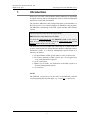
Introduction
Web-server II (1598) is the hardware and the functions are depending
on which software that is downloaded as well as which configuration
data that is created and downloaded.
The software (EBLWeb) and configuration data are downloaded to
the Web-server II via a commissioning tool, EBLWin (a PC program).
The EBLWin is depending on the EBL system and the EBL software
version.
This document describes the following software:
EBLWeb V2.1.0 for Web-server II 1598.
To create the configuration data, the EBLWin V2.1.0 or later shall be
used. It is also used to download both the configuration data and the
software for the Web-server II (1598).
The Web-server II is used when one control unit or a system with two
or more control units in a TLON Network shall be connected to Internet/Intranet (LAN), to a Security Management System and/or as a
Gateway, as follows:
For presentation of EBL-system status in a PC (web browser).
For remote operating of EBL-system, also via encrypted twoway communication if required.
As an e-mail client.
EBLnet (via TCP/IP), for connection of the EBL-system to a
Security Management System.
As a Gateway.
NOTE!
The EBLWin version has to be the same as the EBLWeb software
version regarding the two first digits, e.g. version 2.1.x respectively.
5
Panasonic Eco Solutions Nordic AB
MEW01742 Rev: -
2
Operating instructions EBLWeb V2.1.x
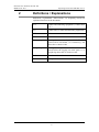
Definitions / Explanations
Definitions / explanations / abbreviations / etc. frequently used or not
explained elsewhere in the document.
C.i.e.
Control and indicating equipment (=control unit;
C.U.)
C.U.
Control unit (=Control and indicating equipment)
S/W
Software
H/W
Hardware
Circular log / list
The log / list re-starts when it is "full". The first
events will be overwritten, i.e. a circular log / list
shows the xx latest events.
Straight log / list
The log / list stops when it is full and has to be
erased before the logging can start again, i.e. a
straight log shows the xx earliest events.
LAN
Local Area Network
SSD
Site Specific Data
6
Panasonic Eco Solutions Nordic AB
MEW01742 Rev: -
3
Operating instructions EBLWeb V2.1.x
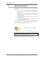
General description
The Web-server II (1598) can be used with one, or more of the following functions:
1. As a web-server for presentation of the actual EBL512G3 /
EBL128 status in a PC using the web browser, via Internet or
Intranet (LAN).
2. As a web-server also for remote operating of an EBL512G3 /
EBL128 and also via encrypted two-way communication
(HTTPS) if required.
3. As an e-mail client to send e-mails in case of special events e.g.
fire alarm, fault, etc.
4. As a Gateway to a separate system, i.e. transmit and present fire
information in another (PC) system.
5. To connect the EBL- system to a Security Management system.
The Web-server II has to be configured and the EBLWeb software has
to be downloaded via EBLWin V2.1.0 or later.
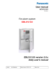
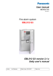
Figure 1. A PC is connected to an EBL512G3 system via Internet/Intranet (LAN) and the Web-server II, 1598.
NOTE! The web-server is normally mounted inside the c.i.e.
7
Panasonic Eco Solutions Nordic AB
MEW01742 Rev: -
3.1
Operating instructions EBLWeb V2.1.x
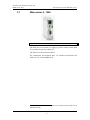
Web-server II, 1598
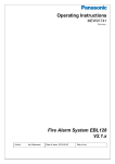
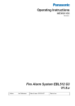
Figure 2. Web-server II, 1598.
The Web-server II consists of a light grey plastic cabinet, which shall
be vertically mounted on a DIN rail.1
The Web-server II has four interfaces.
For connections and technical data, see Technical Description for
Web-server II, 1598 (MEW01035).
1
A symmetric 35mm DIN rail is by delivery mounted inside the EBL512 G3
and EBL128 units.
8
Panasonic Eco Solutions Nordic AB
MEW01742 Rev: -
4
Operating instructions EBLWeb V2.1.x
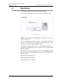
Functions
The following chapters describes all EBLWeb functions.
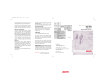
The start page in the browser might look as follows (before login):
NOTE! The look might vary depending on web-browser, screen resolutions, settings etc.
There is no support for anonymous login. A user with at least lowest
priority level is required to be configured via EBLWin, even if webserver is to be used for status information only.
For remote operations and access to corresponding information, a
username and a password are always required for at least user level 2
(Building Officer).
The EBLWeb has to be configured via the PC tool EBLWin 2.1.0 or
later, and it uses the same usernames and passwords as configured for
the EBL-system.
User level 1 (Information Only)
User level 2 (Building Officer)
User level 3 (Service Personnel)
9
Panasonic Eco Solutions Nordic AB
MEW01742 Rev: -
4.1
Operating instructions EBLWeb V2.1.x
User login
Username: Type the Username for the User level respectively
Password: Type the Password for the User level respectively.
Click LOGIN to open Status - summary view.
Depending on the login User level (which is depending on Username
and Password, different buttons can be used, i.e. access to remote operations and other information or general information only.
The view is continuously updated approx. each 10th seconds.
In case of inconsistency between EBLWeb and EBL512G3/EBL128,
a synchronization can be done, e.g. via EBL512G3 menu H8/S7 or
EBLWin 2.1.x. After restart of the Web-server, a synchronization is
done automatically.
10
Panasonic Eco Solutions Nordic AB
MEW01742 Rev: -
4.2
Operating instructions EBLWeb V2.1.x
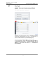
User logout
To logout the current session in EBLWeb, click the logout button in
the upper-right corner.
4.3
Silence PC buzzer (sound off)
When a fire alarm is activated, the buzzer/speaker in the PC is used
for sound alert.
Click the Silence PC buzzer button to silence the buzzer/speaker in the
PC (until a new fire alarm is activated).
11
Panasonic Eco Solutions Nordic AB
MEW01742 Rev: -
4.4
Operating instructions EBLWeb V2.1.x
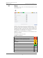
Status
After login or in any other view click home/status button to see the
status summary view.
EBLWeb will present the current status of the EBL-system, i.e. showing current alarms, faults, disablement and other deviations corresponding to the EBL CU. The status will be shown in different webpages and also in the LED buttons on the top of the indication panel.
The LED-buttons will either blink or be constantly lit.
NOTE! The colour in the LED button is not visible until the event respectively is activated.
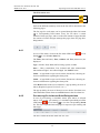
The summary consists of two areas.
The EBL CU status area
Fire alarm
Pre-warning/Co-incidence/Quiet/Delayed alarm
Fault
Disablement
Technical warning
Interlocking
Door open
N/A
Zones in test mode
N/A
Service signal
N/A
Output activation
N/A
12
Panasonic Eco Solutions Nordic AB
MEW01742 Rev: -
Operating instructions EBLWeb V2.1.x
The Web status area
WEB function disablement
Communication error
Each of the different summary items in the list will be described in the
following pages.
The list page for each status can be opened through either list button
or corresponding LED button. Every list can show a certain
amount of items per page, and to see the total amount of pages that the
list consists of, and to navigate amongst the pages, there are page handling buttons.
4.4.1
Fire alarm
In case of fire alarm, click on the fire alarm LED button
button
to view the fire alarm list.
or List
The Time (date and time), Zone, Address and Text (alarm text) are
displayed.
Type = Smoke, Heat, Multi, MCP, Exting.system or Other.
State = Heavy smoke/heat, Test, Isolated and Alert Annunciation
alarm acknowledged / not acknowledged. See NOTE! below.
Link1 = A hyperlink to open a web-camera, document, a drawing etc.
for more information regarding the alarm point.
Link2 = A hyperlink to open a web-camera, document, a drawing etc.
for more information regarding the alarm point.
Click Reset button in the reset column for a pop-up dialog for reset of
alarm. (Requires login on User level 2 or 3.)
The pop-up dialog for reset of alarm gives two choices for alarm reset,
either reset the current alarm or reset all alarms in the fire alarm list.
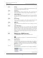
4.4.2
Pre-warning/Co-incidence/Quiet/Delayed alarm
In case of pre-warning, co-incidence alarm, quiet alarm, or delayed
alarm, click on the pre-warning/ Co-incidence/Quiet/Delayed alarm
LED button
or List button
to view the corresponding alarm
list. This list is separated into tab pages for respective pre-warning and
alarm type.
The list is similar to the fire alarm list. See 4.4.1.
13
Panasonic Eco Solutions Nordic AB
MEW01742 Rev: -
4.4.3
Operating instructions EBLWeb V2.1.x
Fault
In case of faults, click on the fault LED button
to view the fault list.
or List button
The Time (date & time), Tech.No, Zone/Address (when applicable),
Fault description (fault message) are displayed. State (Serviced /
Acknowledged / "Blank" = Neither Serviced nor Acknowledged).
Text = More info, such as alarm text if the fault is related to an detector etc. Place the pointer above the information icon.
Link1 = A hyperlink to open a web-camera, document, a drawing etc.
for more information regarding the alarm point.
Link2 = A hyperlink to open a web-camera, document, a drawing etc.
for more information regarding the alarm point.
Click Acknowledge button in the acknowledge column for a pop-up
dialog for acknowledgement of fault. (Requires login on User level 2
or 3.)
The pop-up dialog for acknowledgement of fault gives two choices for
fault acknowledgement, either acknowledge the current fault or
acknowledge all faults in the fault list.
4.4.4
Disablement
In case of disablement , click on the disablement LED button
or
List button
to view the corresponding disablement list. This list is
separated into tab pages for respective disablement type.
Click Re-enable button in the re-enable column for a pop-up dialog
for re-enabling the disablement. (Requires login on User level 2 or 3.)
4.4.4.1
Zone or Zone-Address disablement
The Time (date & time), Zone, Address, Re-enable time and Reason
(e.g. via the menu) is displayed.
Link1 = A hyperlink to open a web-camera, document, a drawing etc.
for more information regarding the alarm point.
Link2 = A hyperlink to open a web-camera, document, a drawing etc.
for more information regarding the alarm point.
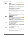
4.4.4.2
Output disablement
The Time (date & time), Control unit, Exp.Board, Loop, and Address is displayed.
Output type = The type of output, such as, Control, Ventilation, Extinguisher, Alarm devices, ATR, Neutral, or FTR.
Output = The output number.
Reason = e.g. via the menu.
14
Panasonic Eco Solutions Nordic AB
MEW01742 Rev: -
4.4.4.3
Operating instructions EBLWeb V2.1.x
Output type disablement
The Time (date & time), and Control unit, is displayed.
Output type = The type of output, such as, Control, Ventilation, Extinguisher, Alarm devices, ATR, Neutral, or FTR.
Reason = e.g. via the menu.
4.4.4.4
Interlocking (output) disablement
The Time (date & time), Area, Point and Text( interlocking text) are
displayed.
4.4.4.5
COM-loop/Input disablement
The Time (date & time), Control unit, Exp.Board, Tech.No., and
Loop (Input) is displayed.
4.4.4.6
Other (Alert annunciation) disablement
The Time (date & time) and Text( disablement text) are displayed.
This list is only showing Alert annunciation disablement.
4.4.5
Technical warning
In case of technical warning, click on the technical warning LED button
or List button
to view the technical warning list.
The Time (date & time) and Text (technical warning text) are displayed.
4.4.6
Interlocking
In case of interlocking input/output activations, click on the interlocking LED button
or List button
to view the interlocking list.
The Time (date and time), Area, Point and Text (interlocking text)
are displayed.
Input = Input is activated.
In.Act.Time = The input activation time.
Output = Output is activated.
Out.Act.Time = The Output activation time.
Click Reset button in the reset column for a pop-up dialog for reset of
activated interlocking output. (Requires login on User level 2 or 3.)
4.4.7
Door open
In case of open doors, click the List button
to view the door list.
The Time (date & time) and Control unit are displayed.
FBP = The number of the Fire Brigade Panel, in case of door opened
at FBP.
4.4.8
Zones in test mode
In case of zones in test mode, click the List button
of zones in test mode.
15
to view the list
Panasonic Eco Solutions Nordic AB
MEW01742 Rev: -
Operating instructions EBLWeb V2.1.x
The Time (date & time) and Zone are displayed.
Click De-activate button in the de-activate column for a pop-up dialog for de-activation of the zone in test. (Requires login on User level
2 or 3.)
4.4.9
Service signal
In case of detectors having activated service signal, click the List button
to view the service signal list.
The Time (date and time), Zone, Address, Tech.No and Text (alarm
text) are displayed.
Link1 = A hyperlink to open a web-camera, document, a drawing etc.
for more information regarding the alarm point.
Link2 = A hyperlink to open a web-camera, document, a drawing etc.
for more information regarding the alarm point.
Click Acknowledge button in the acknowledge column for a pop-up
dialog for acknowledgement of service signal. (Requires login on User
level 3.)
4.4.10
Output activation
In case of forced output activations, click the List button
the output activation list.
to view
The Time (date & time), Control unit, Exp.Board, Loop, and Address is displayed.
Output = The output number.
Click De-activate button in the de-activate column for a pop-up dialog for de-activation of the force activated output. (Requires login on
User level 2 or 3.)
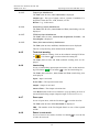
4.4.11
WEB function disablement (WEB status)
In case of any WEB-function disablement, click the WEB function
LED button
or the List button
to view the WEB function disablement list.
This view shows the current status of disablement of WEB functions,
such as E-mails, PC-buzzer, and Gateway. It also shows the timestamp for previous login and current EBLWeb software version.
16
Panasonic Eco Solutions Nordic AB
MEW01742 Rev: -
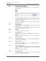
4.4.12
Operating instructions EBLWeb V2.1.x
Communication error
In case of any communication error, click on the communication error
LED button
or the List button
to view the communication error
list.
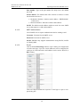
This view shows the current communication state for several kinds of
communication errors as listed. If in error state, the state will be
‘blinking’ Error, otherwise a steady Normal will be shown.
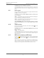
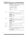
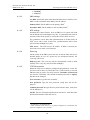
4.5
EBL - WEB
Communication Could be disconnecbetween CU and tion error in serial caWEB-server.
ble.
WEB - Browser
Communication
between WEBserver and
browser
Normally no TCP/IP
connection with
WEB-server from
browser.
E-mail SMTP - WEB
Communication
between SMTPserver and
WEB-server
Normally no access to
SMTP server. No email can be sent.
WEB - Gateway
Communication Normally
no
rebetween WEB- plies/ACK from the
server and cur- gateway device.
rent configured
Gateway function.
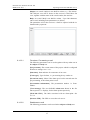
Event log
Click event log button to show the Event log view.
The event log of EBLWeb consists of five types of logs, where three
of them are the same as in the control unit, namely, Alarm log, Interlocking log and General event log. All logs in EBLWeb are circular
logs. The events in an EBL-system are stored in both the
EBL512G3/EBL128 c.i.e. and in the Web-server.2
The Time (date & time), and Event (event text) is displayed.
Description = Additional information of the event when applicable.
User = The user that performed that specific event.
Origin = The source where the event originated from.
2
If the Web-server is disconnected, the events during that time will not be
saved in the Web-server, i.e. not shown in the event log. When you restart
the Web-server, the event log will be erased.
17
Panasonic Eco Solutions Nordic AB
MEW01742 Rev: -
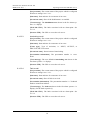
4.5.1
Operating instructions EBLWeb V2.1.x
All log
The all log is a special log in EBLWeb that collect all events in the
same log with a capacity of 9999 log events.
4.5.2
Alarm log
This log contains all alarm related events. This log shall show the
same events as the CU alarm log with a capacity of 999 log events.
4.5.3
Interlocking log
This log contains all interlocking related events. This log shall show
the same events as the CU interlocking log with a capacity of 999 log
events.
4.5.4
General log
This log contains all general events. This log shall show the same
events as the CU general log with a capacity of 999 log events.
4.5.5
WEB log
This log contains all web related events, with a capacity of 999 log
events.
4.5.6
Test mode alarm
This is a log to keep track of the test mode alarms. The test mode
alarms normally goes back to normal after 10 seconds. This test mode
alarm log is used to record the test mode alarms in a list. In this,
there’s a sub-menu to send this list of test mode alarms to a predefined e-mail recipient and also clear the list from all recorded test
mode alarms.
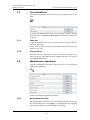
4.6
Maintenance (WEB function)
Click Maintenance button to show the Maintenance view.
This view contains two tab pages, one for WEB functions and the other for Web links.
4.6.1
Web function
The tab page shows WEB function disablement page with operations
to Enable or Disable the WEB function. Each function is Enabled or
Disabled by a selection of the corresponding radio button. Click Apply to perform the action.
4.6.1.1
All e-mail function
This disablement is to stop all kinds of e-mail sending from EBLWeb.
18
Panasonic Eco Solutions Nordic AB
MEW01742 Rev: -
Operating instructions EBLWeb V2.1.x
4.6.1.2
E-mail function
This disablement is related to each type of e-mail, i.e. Fire
alarm/Pre-warning, Disablement, Interlocking, Fault, Service,
Test mode alarm, and Technical warning.
4.6.1.3
PC buzzer function
This disablement is related to the PC-buzzer, that which sound for
each new fire alarm or control unit communication fault.
There is also a button for test of the PC-buzzer (four long beeps).
4.6.1.4
Gateway function
This disablement will stop the Web-server to send messages to the
current configured gateway, such as Tateco, EBLTalk, or SIA.
4.6.1.5
FTP function
This disablement will stop the FTP access to the Web-server.
4.6.1.6
TELNET function
This disablement will stop the TELNET access to the Web-server.
4.6.2
Web link
Web links are URLs used for additional documents or web-cameras
for a defined zone-address/detector. This tab page will show a list of
all web links currently configured via EBLWin.
19
Panasonic Eco Solutions Nordic AB
MEW01742 Rev: -
4.7
Operating instructions EBLWeb V2.1.x
Basic information
Click the basic information button to show the basic information view.
This view has a tab page that shows the user information for currently
logged in user and another tab page for the e-mail address configuration for each e-mail type.
4.7.1
Username/Password)
In this view, the current user may change the user login password
(click Select). The password change requires to input both current
password and the new password. Once applying the password change,
the new password will be changed for the EBL-system as well.
4.7.2
E-mail address
The e-mail handling in EBLWeb handles six different types of emails. Each e-mail type can be disabled. See 4.6.1.2. The EBLWin
configured e-mail addresses for recipients are shown in this tab page.
Each e-mail address shown has a button to send a test mail to the configured e-mail address.
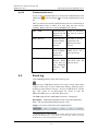
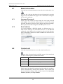
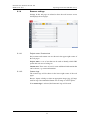
4.8
Control unit
Click the control unit button to access the control unit list view.
This page show all control units in the EBL-system. Each control unit
row has a colored sign for synchronization status.
■ BLACK
Not connected.
■ RED
Synchronization has not started.
■ YELLOW
Synchronization is in progesss.
■ GREEN
Synchronization is finished.
Which control unit should be monitored and be included in synchronization is determined by the SSD from EBLWin. Those control units
that are included according to SSD, will have buttons for Control unit
statistics (Sys.info.) and Loop statistics.
20
Panasonic Eco Solutions Nordic AB
MEW01742 Rev: -
4.8.1
Operating instructions EBLWeb V2.1.x
Control unit statistics (System information)
This page shows the system information of selected CU and consist of
momentary statistics data asked from the connected CU.
The current consumption for rectifier, current consumption for
charger, battery temperature, low capacity voltage difference, site
name (also time of SSD download) and software version for the CU
is displayed.
4.8.2
Loop statistics
This page shows the COM loop statistics for communication in selected CU.
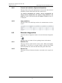
4.9
Detector diagnostics
Click the detector diagnostics button to access the detector diagnostic
page.
This page show two kinds of lists regarding detector informations.
4.9.1
Detector list
This page asks the control unit for sensor values. When selecting Detector list, it will first give an input window. Specify from which
technical number the sensor list shall start asking the control units.
4.9.2
Service list
This page will list all detectors that have activated service signal. See
4.4.9.
21
Panasonic Eco Solutions Nordic AB
MEW01742 Rev: -
5
Operating instructions EBLWeb V2.1.x
Remote operations
To access remote operation in EBLWeb, click the remote operation
button.
It will expand the submenu for different remote operations, which
consists of four main types:
Disablement
Activation
Test
Maintenance
The remote operations are user dependent, which means that some
menues or operations will be hidden from users with insufficient user
level.
Most of the remote operations have feedback functions to check if the
operation was executed successfully, partly successfully, or not executed. But there are also operations that doesn’t give any feedback, i.e.
“one-shot operations”.
Operation succeeded
Operation partly succeeded
Operation failed
22
Panasonic Eco Solutions Nordic AB
MEW01742 Rev: -
5.1
Operating instructions EBLWeb V2.1.x
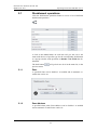
Disablement operations
Click the disablement operations button to access a list of different
disablement operations.
A click on the select button on each item will give the user a sub
menu with choices of specific type for the corresponding disablement
or a pop-up window with operations to Disable or Re-enable the disablement.
The back-button
previous menu.
5.1.1
will go back one level in the menu list, to the
Zone
A specified Zone can be disabled / re-enabled and an automatic reenable time can be set.
5.1.2
Zone-Address
A specified alarm point (Zone-Address) can be disabled / re-enabled
and an automatic re-enable time can be set.
23
Panasonic Eco Solutions Nordic AB
MEW01742 Rev: -
5.1.3
Operating instructions EBLWeb V2.1.x
Output
A sub menu for several types of outputs:
5.1.3.1
Loop unit output
A specified loop unit (tech.no.), output (0-2) can be disabled / reenabled.
NOTE! In system EBL128 the tech.no. is “000” plus the COM loop
address, e.g. 000123.
5.1.3.2
Voltage output (S)
A specified voltage output (0-3) in a specified control unit (00-29)
can be disabled / re-enabled.
5.1.3.3
Relay output (R)
A specified relay output (0-1) in a specified control unit (00-29) can
be disabled / re-enabled.
5.1.3.4
Expansion board output
A specified output (0-7) on a specified 4581/4583 expansion board
(0-5), in a specified control unit (00-29), can be disabled / re-enabled.
NOTE! 4583 has three outputs(0-2).
5.1.3.5
Interlocking output
An interlocking can be disabled / re-enabled via a specified interlocking combination Area-Point.
5.1.4
Output type
A sub menu for several types of outputs. All outputs of the type respectively will be collectively disabled/re-enabled.
5.1.4.1
Control output
All outputs of type "control", can be collectively disabled / re-enabled
(all at the same time) in all control units or in a specified control unit
(00-29).
5.1.4.2
Ventilation output
All outputs of type "ventilation", can be collectively disabled / reenabled (all at the same time) in all control units or in a specified control unit (00-29).
24
Panasonic Eco Solutions Nordic AB
MEW01742 Rev: -
Operating instructions EBLWeb V2.1.x
5.1.4.3
Extinguishing output
All outputs of type "extinguishing", can be collectively disabled / reenabled (all at the same time) in all control units or in a specified control unit (00-29).
5.1.4.4
Interlocking output
All outputs of type "interlocking", can be collectively disabled / reenabled (all at the same time) in all control units or in a specified control unit (00-29).
5.1.5
Alarm devices
All outputs of type "alarm devices", can be collectively disabled / reenabled (all at the same time) in all control units.
5.1.6
Routing equipment
A submenu with Fire routing equipment and Fault routing equipment.
5.1.6.1
Fire routing equipment
The FIRE output for routing equipment (fire brigade tx) can be disabled / re-enabled.
5.1.6.2
Fault routing equipment
The FAULT output for routing equipment (fault tx) can be disabled /
re-enabled.
5.1.7
Alert annunciation
The Alert Annunciation function can be disabled / re-enabled.
NOTE! This operation has higher priority than any time channel controlling this function.
5.1.8
COM-loop / Zone line input
A sub menu with the three types that can be disabled.
5.1.8.1
COM-loop
A specified COM Loop (0-3) in a specified Control Unit (00-29) can
be disabled / re-enabled.
5.1.8.2
Zone line input
A specified zone line input (0-7) on a specified 8 zones expansion
Board (0-5), in a specified Control Unit (00-29), can be disabled / reenabled.
5.1.8.3
Zone interface
The zone line input (0) on a specified COM loop unit (3361) / technical number (Tech. No.), can be disabled / re-enabled.
NOTE! In system EBL128 the tech.no. is “000” plus the COM loop
address, e.g. 000123.
25
Panasonic Eco Solutions Nordic AB
MEW01742 Rev: -
5.2
Operating instructions EBLWeb V2.1.x
Activation operations
Click the activation operations button to access a list of different activation operations.
A click on the select button on each item will give the user a sub
menu with the different output types or a pop-up window with buttons
to Activate or De-activate.
The back-button
previous menu.
5.2.1
will go back one level in the menu list, to the
Zone-Address
A specified alarm point (Zone-Address) can be activated, i.e. set in
fire alarm mode.
Reset the fire alarm with the de-activate button or in the fire alarm
list, like any other fire alarm, see 4.4.1.
5.2.2
Output
A sub menu for several types of outputs.
5.2.2.1
Loop unit output
A specified loop unit (Tech. No.), Output (0-2) can be activated / deactivated.
NOTE! In system EBL128 the tech.no. is “000” plus the COM loop
address, e.g. 000123.
5.2.2.2
Voltage output (S)
A specified voltage Output (0-3) in a specified Control Unit (00-29)
can be activated / de-activated.
5.2.2.3
Relay output (R)
A specified relay Output (0-1) in a specified Control Unit (00-29)
can be activated / de-activated.
5.2.2.4
Expansion board output
A specified output (0-7) on a specified 4581/4583 expansion board
(0-5), in a specified control unit (00-29), can be activated / deactivated.
NOTE! 4583 has three outputs(0-2).
5.2.2.5
Interlocking output
An interlocking output can be activated / de-activated via a specified
interlocking combination Area-Point.
26
Panasonic Eco Solutions Nordic AB
MEW01742 Rev: -
5.3
Operating instructions EBLWeb V2.1.x
Test operations
Click the test operations button to access a list of different test operations.
A click on the select button on each item will open a pop-up window
with operations to Activate or De-activate the Zone test or Alarm devices test.
5.3.1
Zone test
A specified zone (0-999) can be set in test mode, i.e. test mode activated / de-activated.
Zones in test mode can also be de-activated from the Zones in test
mode list. See 4.4.8.
5.3.2
Alarm devices
All outputs of type "alarm device" can be collectively activated / deactivated for test. All at the same time in all control units or in a specified control unit (00-29).
5.4
Maintenance operations
Click the maintenance operations button to access a list of different
maintenance operations.
A click on the select button on each item will open a pop-up window
with corresponding maintenance operation.
5.4.1
Set calendar and time
The date and time for the web-server and the EBL system can be set in
the pop-up dialog box. Click apply to set the date and time currently
shown in the dialog box or click cancel for no change.
27
Panasonic Eco Solutions Nordic AB
MEW01742 Rev: -
5.4.2
Operating instructions EBLWeb V2.1.x
Synchronize
This operation starts a synchronization of the EBL-system, which includes EBL CU, EBLWin, and EBLWeb. The synchronization status
of each Control unit is shown in the Control unit list. See 4.8.
5.4.3
Silence alarm devices
This operation works like the silence alarm devices button on the
control unit front.
NOTE! Cannot be activated if there is no fire alarm in the system.
5.4.4
Evacuate
This operation activates / de-activates the evacuate function.
5.4.5
Sensitive fault detection mode
This operation activate / de-activate the EBL-system for sensitive fault
detection mode.
5.4.6
Calibrate outputs
This operation starts a calibration of all supervised outputs in the EBL
system.
5.4.7
Close fire doors
This operation will collectively close all fire doors, i.e. programmable
outputs with a control expression containing one or more trigger conditions Fire Door Closing (zone – address), in all control units or in a
specified control unit (00-29).
5.4.8
Fire drill mode
Fire drill mode activated will disable all outputs except outputs of type
Control neutral and type Alarm devices.
An alarm point activating fire alarm will now activate all alarm devices, in order to evacuate the building (a fire drill).
28
Panasonic Eco Solutions Nordic AB
MEW01742 Rev: -
6
Operating instructions EBLWeb V2.1.x
Configuration of EBLWeb
The EBLWeb is configured via the PC tool, EBLWin 2.1.0 or later.
The EBLWeb software, the configuration data and the site specific data (SSD) will be downloaded to the web-server via TCP/IP3. See
EBLWin, menu Tools.
All the EBLWeb related menu options and dialog boxes in EBLWin
are described in the following chapters.
6.1
Web-server
To configure a web-server for the EBL-system, a web-server must be
added to a control unit (Control unit pop-up menu, Add web-server).
Up to five web-servers may be added to the EBL-system, with a limit
of one web-server per control unit.
Once added, a properties dialog box for the Web-server will be
opened. More about each setting will be described below. The properties dialog box can always be accessed by right-clicking at a webserver in the EBLWin treeview, and select properties.
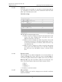
6.1.1
General information
Since there is a limitation of the maximum numbers of web-servers
for a EBL system, each web-server must have a unique technical address (0-4). A default web-server Name is shown. The web-server
name is shown in the treeview of EBLWin.
6.1.2
Unit information
To be able to download a specific configuration to a specific webserver, the Hardware ID (normally five characters) is required to
identify the web server unit. This ID can be found in the label on the
backside of Web-server II 1598. (ID:12345)
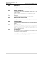
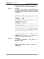
6.1.3
Unit settings
6.1.3.1
IP address settings
Use DHCP: Select this option when a dynamic IP number shall be
used (instead of a static, see below).
Device name: It is always recommended to have a Device name, not
only when a dynamic IP number is used.
If a static IP number shall be used the following data have to be specified:
IP address (for web-server)4
3
The Web-server 1598 and the PC both have to be connected to the Local
Area Network (LAN). As an alternative a "Crossed network cable" or a Hub
can be used.
4
The IP address is by delivery set to 192.168.1.169. If the Local Area Network (LAN) administrator demands another IP address to be used, it can be
changed via the PC tool CHIPTOOL provided free of charge by BECK IPC
website: http://www.beck-ipc.com
29
Panasonic Eco Solutions Nordic AB
MEW01742 Rev: -
Operating instructions EBLWeb V2.1.x
Netmask5
Gateway5
6.1.3.2
DNS settings
Use DNS: Select this option when Domain Name Server shall be used.
DNS is used to translate name address into IP address.
Primary DNS: The IP address to the primary DNS5.
Secondary DNS: The IP address to the secondary DNS5.
6.1.3.3
NTP settings
Normally the Control Unit no. 00 in an EBL512 G3 system will send
out the date & time at midnight every day, to synchronize the clock in
all control units in the system as well as the clock in Web-server II.
For continuous correct time and synchronization of all the clocks an
NTP6 server can be used. In this case, synchronization will be done
one hour after midnight every day.
NTP server: The NTP server's IP address. If DNS is selected (see
above) the server name is used instead.
6.1.3.4
Event log
All the events in the EBL-system will also be stored in the web-server
internal RAM. In case of a power-loss (or unexpected reboot), the
event log will be lost.
Daily log save: The event log will be automatically saved to flash
memory once every day (one hour after midnight).
6.1.3.5
FTP/Telnet access
When the Web-server shall be configured (programmed) via the PC
tool, this will be done via FTP/Telnet via a LAN network (or crossed
Ethernet cable or a hub). For safety reasons, Username and Password
are used for FTP/Telnet. The default username/password are ftp/ftp,
but this can be changed.
New username: Type the new username.
New password: Type the new password. (Only dots will be displayed.)
Confirm password: Re-type the new password once more. (Only dots
will be displayed.)
NOTE! The new Username and Password will not be valid until after
download and restart of the Web-server.
5
Provided by LAN administrator.
NTP (Network Time Server) is a protocol designed to synchronize the
clocks of computers over a network.
6
30
Panasonic Eco Solutions Nordic AB
MEW01742 Rev: -
6.1.4
Operating instructions EBLWeb V2.1.x
Browser settings
Settings in this tab page are related to how the web browser access
and displays the web pages.
6.1.4.1
Project name / Custom text
Project name and custom text are shown in the upper-right corner of
the web pages.
Project name: a row of text that can be used to identify which EBL
system this web server belongs to.
Custom text: Three rows of text for some additional information that
can be shown, e.g. contact information.
6.1.4.2
Custom logo
The custom logo will be shown in the lower-right corner of the web
pages.
Browse: Opens a dialog to select an appropriate image (jpg, gif, bmp)
used for logo. Recommended format size of image is 210x56 pixels.
If no custom logo is selected, the Panasonic logo will be used.
31
Panasonic Eco Solutions Nordic AB
MEW01742 Rev: -
6.1.4.3
Operating instructions EBLWeb V2.1.x
Web link
If an alarm point is presented, it is possible to click the hyperlink for
e.g. a document or a camera to get more information about the alarm
point. Up to 500 links can be used.
Web links settings
The web links are based on three levels:
Level 1 is used to configure two links for all alarm points in the
system. The links configured here will fully cover zoneaddresses from 001-01 to 999-99.
Level 2 is used to configure two links for specific zones in the
system.One zone per row. The links configured here will cover a full zone from ZZZ-01 to ZZZ-99, where ZZZ can be any
zone from 001-999.
Level 3 is used to configure two links for specific alarm points
in the system. One alarm point per row. The links configured
here will cover one zone-address. 001-01 to 999-99 can be
used.
6.1.4.4
Browser access
The web pages are by default configured to be accessed without encryption with http, but if more safety for access is needed, https access with encrypted communication via SSL can be used. (See below.)
Browser URL: Type the web-address (URL) for accessing this webserver. This will be used as Web-server URL in e-mails, if used.
http://x
https://x
http/https://x
x = IP-address or the Device name.
6.1.4.5
SSL certificate
If https is going to be used for webpage access, the SSL certificates
needs to be defined.
32
Panasonic Eco Solutions Nordic AB
MEW01742 Rev: -
Operating instructions EBLWeb V2.1.x
There are two ways to define SSL certificates in the configuration. Either self-issued certificate or vendor-issued certificate can be used.
6.1.4.5.1
Self-issued
It is possible to create certificates in the configuration tool in
EBLWin, but the certificate it creates using OpenSSL are not verified
by any trusted certificate authority, thus a warning might be shown in
the web browser.
Click the Create button to open dialog to create certificate.
Once created the create button will change to completed to show that
the certificate already has been created.
The Retrieve button is used to retrieve and save the current certificate
(CACERT.crt) in some other place in the computer (PC).
6.1.4.5.2
Vendor issued
If the certificates are vendor-issued, it can be configured to the
EBLWeb with this option.
CA certificate: Type the path and file name (e.g. intermed.pem) or
use the Browse button.
Private key: Type the path and file name (e.g. privkey.pem) or use
the Browse button.
Server certificate: Type the path and file name (e.g. cert.pem) or use
the Browse button.
33
Panasonic Eco Solutions Nordic AB
MEW01742 Rev: -
6.1.5
Operating instructions EBLWeb V2.1.x
Gateway/EBLNet settings
The EBLWeb is not only a web-server but can also be a gateway to
another system.
One of the following gateway types can be selected:
None: No gateway function will be used.
Tateco: Used when fire alarm information shall be transmitted
to and presented in an Ascom Tateco paging system.
EBLTalk: Used when fire alarm information shall be transmitted to and presented in a separate PC system, via RS232 or via
TCP/IP. EBL Talk is an open protocol. For more information
see "EBL Talk Protocol" Technical Description
(MEW00532).
SIA: Used when fire alarm information shall be transmitted to
and presented in a separate PC system, via the SIA protocol.
MODBUS: Used when fire information shall be transmitted via
MODBUS protocol. Only occurrence of fire alarm per zone is
registered.
6.1.5.1
COM port settings
COM port settings are used for the serial communication (RS232) setup used with EBLTalk or Tateco protocols.
Normally defaults settings are used for EBLTalk or Tateco, but it’s
possible to change to suitable settings depending on corresponding
client communication settings.
Click Reset defaults button to restore the defauls settings for COM
port.
6.1.5.2
EBLTalk settings
EBLTalk can be used via COM-port (RS232) or via Ethernet TCP/IP
port.
6.1.5.3
SIA settings
Client IP (MAS) address and Sender ID are required. (Provided via
the Local Area Network (LAN) administrator and/or SIA administrator.)
6.1.5.4
Tateco settings
Tateco uses a COM-port and need a Tateco file to be defined. A tateco
file has to either be created (Create) or an existing file has be selected
(Browse).
6.1.5.5
MODBus settings
MODBUS uses a COM-port and only 8 bits data with 1 stopbit is supported. A slave ID needs to be defined which is used by a Modbus
software to retrieve data.
34
Panasonic Eco Solutions Nordic AB
MEW01742 Rev: -
6.1.5.6
Operating instructions EBLWeb V2.1.x
EBLnet settings
EBLnet is used to connect the EBL system to a Security Management
system.
EBLnet licence 5097 is a kit containing:
EBLnet licence number document
EBLnet licence number label
User instructions (MEW01479)
Use EBLnet: Has to be selected to activate the EBLnet function.
This has to be done before the Web-server can be connected to the Security Management system.
NOTE! An EBLnet key is also required. How to receive it and use it
is described in the User instructions (MEW01479).
Port number: A port shall be set. Provided via the Local Area Network (LAN) administrator.
NOTE! Port 80 is used for the Web-server and cannot be used here
and if the Gateway function "EBLTalk (TCP/IP)" is used, its port cannot be used here (see 6.1.3.2).
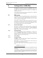
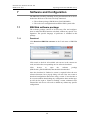
6.1.6
Notification settings
The web-server can be configured to send e-mails if some type of
events occurs. Six different types of e-mails, based on the type of
events, can be sent.
6.1.6.1
SMTP server
IP address / Server name: Type in the IP address for a SMTP server
or type in the SMTP server name if DNS is used. See 6.1.1.2.
35
Panasonic Eco Solutions Nordic AB
MEW01742 Rev: -
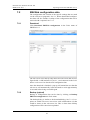
Operating instructions EBLWeb V2.1.x
Port number: Type in the port number for smtp server, the default
port is 25.
Sender address: The address that will be shown as sender in e-mails
sent from the web-server.
Unchecked checkbox: default sender address “EBLWebMail”
will be used.
Checked checkbox: Write the wanted sender address.
NOTE! The default sender address might not work for some SMTP
servers that requires a valid sender address.
6.1.6.2
SMTP authentication
Used if SMTP server requires authentication before sending e-mail.
Username: Username for the SMTP server.
Password: Password for SMTP server.
NOTE! EBLWeb only supports authentication using PLAIN, LOGIN
or CRAM_MD5.
6.1.6.3
E-mail
Click on the E-mail settings button to open a dialog for configuration
of each e-mail type. Up to five e-mail addresses can be configured for
each type of e-mail and each e-mail address can be send as To, CC, or
BCC address.
Click on Compose button for respective e-mail type to open a compose dialog box.
36
Panasonic Eco Solutions Nordic AB
MEW01742 Rev: -
Operating instructions EBLWeb V2.1.x
Subject: An e-mail "Subject" text shall be written, e.g. "Fire alarm".
The "Subject" text will be shown in the receivers e-mail Inbox list
view, together with the name of the e-mail sender, date and size.
Body: An e-mail "Body" text shall be written. Up to 500 characters
can be used, including some parameters (see below).
The parameters will in the receiver's e-mail be replaced with the information they represent.
6.1.6.3.1
Fire alarm / Pre-warning e-mail
The following parameters can be used together with any other text in
the subject and body text.
{Project name}: The custom name of the project which is configured
in Browser settings. See 6.1.2.1.
{Date time}: Date and time for occurrence of an event.
{Event type}: Type of alarm, i.e. pre-warning, heavy smoke etc.
{De-activate state}: Show if the alarm goes back to normal state for
pre-prewarning, or the alarm point is reset.
{Presentation information}: The presentation number i.e. Zoneaddress.
{Text message}: The user definable alarm text shown in the fire
alarm system c.i.e. displays, for the alarm point respectively.
{Web link URL}: The links associated with an alarm-point. See
6.1.2.4.
{Browser URL}: The URL to access the web-server.
6.1.6.3.2
Disablement e-mail
The following parameters can be used in the subject and body text.
37
Panasonic Eco Solutions Nordic AB
MEW01742 Rev: -
Operating instructions EBLWeb V2.1.x
{Project name}: The custom name of the project which is configured
in Browser settings. See 6.1.2.1.
{Date time}: Date and time for occurrence of an event.
{De-activate state}: Show if the disablement is re-enabled.
{Text message}: The disablement text shown in the fire alarm system c.i.e. displays.
{Web link URL}: The links associated with an alarm-point. See
6.1.2.4.
{Browser URL}: The URL to access the web-server.
6.1.6.3.3
Interlocking e-mail
{Project name}: The custom name of the project which is configured
in Browser settings. See 6.1.2.1.
{Date time}: Date and time for occurrence of an event.
{Event type}: Type of activation, i.e. INPUT, OUTPUT, or
INPUT/OUTPUT activation.
{De-activate state}: De-activation of interlocking.
{Presentation information}: The presentation number i.e. AreaPoint.
{Text message}: The user definable interlocking text shown in the
fire alarm system c.i.e. displays.
{Browser URL}: The URL to access the web-server.
6.1.6.3.4
Fault e-mail
{Project name}: The custom name of the project which is configured
in Browser settings. See 6.1.2.1.
{Date time}: Date and time for occurrence of an event.
{De-activate state}: Show if fault is serviced.
{Presentation information}: The presentation number i.e. Technical
number or/and Zone-address.
{Text message}: The fault text shown in the fire alarm system c.i.e.
displays, for the fault respectively.
{Web link URL}: The links associated with an alarm-point. See
6.1.2.4.
{Browser URL}: The URL to access the web-server.
38
Panasonic Eco Solutions Nordic AB
MEW01742 Rev: -
6.1.6.3.5
Operating instructions EBLWeb V2.1.x
Service / contamination e-mail
{Project name}: The custom name of the project which is configured
in Browser settings. See 6.1.2.1.
{Date time}: Date and time for occurrence an event.
{De-activate state}: Show if service signal is acknowledged.
{Presentation information}: The presentation number i.e. Zoneaddress.
{Web link URL}: The links associated with an alarm-point. See
6.1.2.4.
{Browser URL}: The URL to access the web-server.
6.1.6.3.6
Test mode e-mail
{Project name}: The custom name of the project which is configured
in Browser settings. See 6.1.2.1.
{Browser URL}: The URL to access the web-server.
NOTE! The body text will automatically also show a list of the tested
alarm points.
6.1.6.3.7
Technical warning e-mail
{Project name}: The custom name of the project which is configured
in Browser settings. See 6.1.2.1.
{Date time}: Date and time for occurrence of an event.
{De-activate state}: Show if technical warning is serviced.
{Text message}: The technical warning text shown in the fire alarm
system c.i.e. displays, for the technical warning respectively.
{Browser URL}: The URL to access the web-server.
39
Panasonic Eco Solutions Nordic AB
MEW01742 Rev: -
7
Operating instructions EBLWeb V2.1.x
Software and Configuration
The EBLWeb is mainly consisting of two parts that need to be downloaded into Web-server II 1598, to be fully functional.
The software package (EBLWeb210_ENGLISH.BIN)
The web-server configuration data and the EBL-system SSD.
7.1
EBLWeb software package
The software package consists of all necessary files and configurations to make EBLWeb function as default, without any specific configuration. The specific language of preference is included in this
package.
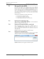
7.1.1
Download
Click Download EBLWeb software in the Tools menu of EBLWin
2.1.0.
Click search to look for all available web-servers in the current network, and select the corresponding one for software download.
Click
browse
to
open
the
software
(EBLWeb210_ENGLISH.BIN) that should be downloaded.
package
Once the download is finished, a restart is required before the new
software functions, but a pop-up dialog will ask if the user wants to
download configuration data before doing a restart. If user decides to
do a restart without downloading any configuration data, another popup will ask for login to Telnet for making a restart command. Once
restarted the web-server will work as default any without any specific
configuration.
40
Panasonic Eco Solutions Nordic AB
MEW01742 Rev: -
7.2
Operating instructions EBLWeb V2.1.x
EBLWeb configuration data
The configuration data consists of the specific settings that are made
via the web-server properties. See 6.1. When downloaded configuration data will also include a backup of the configuration that can be
retrieved with via upload. See 7.2.2.
7.2.1
Download
Click Download EBLWeb configuration in the Tools menu of
EBLWin 2.1.0.
The web-server list in the top only shows all web-servers that are configured with a valid hardware id (see 6.1.) and connected to the LAN.
Select a web-server for download of configuration data.
Once the download is finished, a pop-up will remind the user that the
web-server will automatically restart and needs to wait approximately
30 seconds before being accessible again.
7.2.2
Backup (upload)
Backup of configuration data can be done by clicking on Backup
EBLWeb configuration in Tools menu.
The backup dialog is similar to the download dialog. See 7.2.1. It requires an added web-server in treeview with valid hardware id, that
would be shown in the web-server list. This is where there backup
configuration will be stored once uploaded.
41
Panasonic Eco Solutions Nordic AB
MEW01742 Rev: -
7.3
Operating instructions EBLWeb V2.1.x
Site specific data (SSD)
Site specific data (SSD) is user configurable data from the EBLWin
that is used in the EBL system including all control units. This data
includes specific data such as, user data and alarm points in the system, etc. This SSD needs to be downloaded into the web-server as
well, since the EBLWeb needs the user data for its user handling system, and also for keeping track of how many control units the EBL
system consists of.
The download of SSD data can be done in three ways.
Via download of configuration data.
Via download of SSD for control units.
Via individually download for each web-server.
7.3.1
Download via configuration data
This is done by checking Include SSD Data via the download of
EBLWeb configuration dialog. See 7.2.1.
7.3.2
Download via Download SSD for control units
When downloading SSD for control units in EBLWin, there is a
choice to Download webserver SSD in the dialog box. If this is selected, the SSD will be download for each connected web-server in
each control unit.
NOTE! EBLWin has to be logged on to the EBL system.
7.3.3
Download via individual menu
The SSD can be specifically downloaded to each web-server by rightclicking in respective web-server and select Download SSD….
NOTE! EBLWin has to be logged in on the EBL system.
42
Panasonic Eco Solutions Nordic AB
MEW01742 Rev: -
8
Operating instructions EBLWeb V2.1.x
Installation / Commissioning
Web-server II (1598) is used in the EBL512 G3 system or EBL128. It
is intended for indoor use and in dry premises.
Web-server II shall be vertically mounted on the symmetric 35 mm
DIN rail inside a c.i.e.
The Web-server II has an RJ-45 connector for a standard Ethernet
CAT.5 cable, to be used to connect the Web-server II to Internet / an
intranet (LAN). (The cable is not supplied.)
EBL512 G3
One 0.65 m RS232 cable with a 3 ways Molex plug is supplied, to
connect the Web-server II to the EBL512 G3 c.i.e. main board header
"J7". On the Web-server plug-in connector PLC COM. (RS232C)
there are screw terminals for the yellow, green and black wires.
One 0.65 m power supply cable is supplied. Plug the connector near
the black EMI filter into the Web-server II power supply header. Remove the other cable plug. There are screw terminals on the EBL512
G3 c.i.e. main board for the brown, blue ("J3:1-2") and green ("J2:3")
wires.
See also EBL512 G3 drawing 512 G3 – 32
EBL128
An RS232 cable, 0.65 m, with a 3 ways Molex plug is supplied to
connect the web-server to connector "J5" at the EBL128 main board.
On the Web-server plug-in connector PLC COM. (RS232C) there are
screw terminals for the yellow, green and black wires.
A cable, 0.65 m, with a plug-in connector (Molex 3.5), is supplied to
connect the web-server to connector "J4" at the EBL128 main board.
See also EBL128 drawing 128-25.
Gateway connection
The web-server has a 9 ways male "D" connector MODEM COM.
(RS232C), to be used to connect the Web-server II to a separate PC
system, etc. e.g. when one of the gateway functions is used. (The cable is not supplied.)
See also Web-server II (1598) Technical Description (MEW01035).
43
Panasonic Eco Solutions Nordic AB
MEW01742 Rev: -
8.1
Operating instructions EBLWeb V2.1.x
LED indicators
There are three LED indicators on the Web-server II:
POWER: Indicating that the power supply is connected and is
working.
COM: Indicating:
o
Ethernet connection (continuously)
o
Ethernet data exchange (blinking)
COM: Not used.
44
Panasonic Eco Solutions Nordic AB
MEW01742 Rev: -
9
Operating instructions EBLWeb V2.1.x
Connections
For EBL512 G3, see drawing 512 G3 – 32, and for EBL128, see
drawing 128 – 25.
See also the supplied Web-server Installation Detail.
More information is also found in the Web-server II (1598) Technical
Description (MEW01035).
45
Panasonic Eco Solutions Nordic AB
MEW01742 Rev: -
Operating instructions EBLWeb V2.1.x
10
Revision history
10.1
Rev –
Document created.
46