1
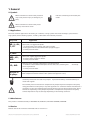
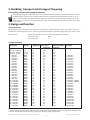
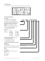
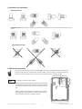
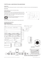
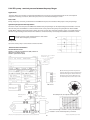
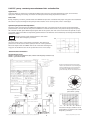
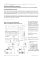
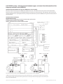
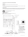
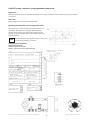
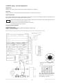
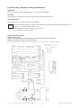
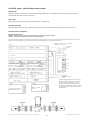
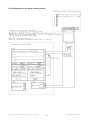
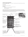
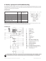
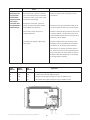
SARJAT
AE_-,
L_-,
AL_-,
T- and
AT-
OPERATING INSTRUCTIONS
CENTRIFUGAL PUMPS WITH INTEGRATED FREQUENCY CONVERTER
FC_ -SERIES
\\W2s\users\minnara\käyttöhjeet\Kolmeks_FCkäyttöohje\Manual_FCpumps_en_20080506.indd
Subject to change without prior notice
Content
1. General............................................................................................. 3
1.1 Symbols................................................................................................................................................. 3
1.2 Applications......................................................................................................................................... 3
1.3 Manufacturer....................................................................................................................................... 3
1.4 Version.................................................................................................................................................. 3
2.1 Handling, transport and storage of the pump................................................................................... 4
2. Handling, transport and storage of the pump.............................4
3. Design and function.......................................................................4
3.1 Construction......................................................................................................................................... 4
3.2 Technical data...................................................................................................................................... 4
3.3 Rating plate........................................................................................................................................ 5
3.4 Pump identification............................................................................................................................ 5
4. Safety............................................................................................. 6
4.1 Safety instructions.............................................................................................................................. 6
4.3 Elements of danger if safety regulations are not obeyed................................................................ 6
4.4 Safety instructions for inspection and assembly.............................................................................. 6
4.2 Training................................................................................................................................................ 6
4.5 Operating the pump........................................................................................................................... 6
5. Installation, introduction and start-up......................................... 6
5.1 General.................................................................................................................................................. 6
5.2 Positions for installation.....................................................................................................................7
5.3 Electrical connections..........................................................................................................................7
5.4 Control methods and connections..................................................................................................... 8
5.4.1 I/O’s of the FC-pump (inputs and outputs)..................................................................................... 8
5.4.2 Factory settings............................................................................................................................... 8
5.4.3 FCA -pump - speed reference from potentiometer....................................................................... 9
5.4.4 FCB -pump - constant pressure between the pump flanges.......................................................10
5.4.5 FCC -pump - constant pressure between inlet- and outlet-line....................................................11
5.4.6 FCCVAK -pump - constant pressure between supply- and return-line with
external controller in use (SETUP 1)........................................................................................................ 12
5.4.7 FCCVAK -pump - constant pressure between supply- and return-line with
controller of the frequency converter in use (SETUP 2)......................................................................... 13
5.4.8 FCD -pump - constant pressure in discharge flange.....................................................................14
5.4.9 FCE -pump - sensorless, pre-programmed pump curves............................................................. 15
5.4.10 FCF -pump - constant temperature............................................................................................. 16
5.4.11 FCF -pump - the speed according to temperature....................................................................... 17
5.4.12 FCG -pump - controlled by external system.................................................................................18
5.4.13 Connections to the alarm receiving station.................................................................................. 19
5.4.14 Local control panel (optional)....................................................................................................... 20
6. Service, spare parts and troubleshooting................................... 22
6.1 Shaft seals......................................................................................................................................... 22
6.2 Other parts........................................................................................................................................ 22
6.3 Troubleshooting................................................................................................................................ 23
7. Declaration of Conformity............................................................ 27
\\W2s\users\minnara\käyttöhjeet\Kolmeks_FCkäyttöohje\Manual_FCpumps_en_20080506.indd
Subject to change without prior notice
1. General
1.1 Symbols
Warns that failure to observe the precaution
may cause personal injury or damage to property.
Indicates something to be noted by the
reader.
Warns that failure to observe the precaution may cause electric shock
1.2 Applications
The most common applications are heating, air condition, cooling systems. Also heat exchangers, pressure boosting systems, district heating systems, ice halls, public baths and industrial processies.
Pump series
AE-, L-, AL-,
T-, AT-
Clean, thin, non-aggressive liquids. - circulating water in for heating and cooling systems
- water-glycol mixtures. Recommendation: propylene glycol
- nominal pressure 10 bar.
L-, ALH-
- like in L- and AL -series, but nominal pressure 16 bar.
AEP-, LP-,
ALP-
Clean, thin, slightly aggressive liquids. - domestic water, oxygen rich waters
- nominal pressure 10 bar.
Applications
LS-, ALS-
Agressive, thin, not bigger solid particles containing liquids
- in addition to above mentioned liquids various acids, salts, oxidizing and
active organic fluids
- nominal pressure 16 bar.
All types of
Temperature range: -10 ... + 95 °C (continuous + 80°C)
Max. temperature of environment +40°C (diurnal average max. +35°C)
FC-pumps
chemically
Suitability of materials and seals for pumped liquid shall be always checked between purchaser and supplier.
The nominal pressure and the max. temperature of pumped liquid are stamped on the pump
rating plate. Never use the pump in any other application or conditions without manufacturer’s
acceptance. In the case of damage there may be danger to persons by having poisoning, burns,
wounds etc. depending on the pumped liquid and it’s temperature and pressure. The pump
surface temperature may cause danger depending on the working conditions.
1.3 Manufacturer
This product is manufactured by OY KOLMEKS AB, P.O.BOX 27, FIN-14201 TURENKI, FINLAND.
1.4 Version
Release date of this manual is 04.01.2005. This is version no. 5.
\\W2s\users\minnara\käyttöhjeet\Kolmeks_FCkäyttöohje\Manual_FCpumps_en_20080506.indd
Subject to change without prior notice
2. Handling, transport and storage of the pump
2.1 Handling, transport and storage of the pump
Normally the pumps are stable when they are transported and don’t go down even they are bent 10°. Pumps
shall be stored in a dry and cool place protected from dust. Temperature of environment must be in -10 °C ...
+50°C. It is not allowed to lift the pump from frequency converter. In the case of longer storage time or the
pump serves as a stand-by, it is recommended to rotate the pump manually f.ex. from the motor fan at least
once a month.
3. Design and function
3.1 Construction
The pump and motor constitute a unit, where the rotating parts of both the pump and the motor are on the same
shaft (mono-block design). The motor is of a dry type and the frequency converter is integrated to the electric motor.
Electric motor:
Totally enclosed, fan cooled A.C. motor, with frequency converter.
Protection form: IP54
Insulating class: F
3.2 Technical data
Pump type
Flanges
Weight kg(* Max. input
Nominal current Twin pump
power kW
A (400 V)
AE_-25/4,-26/4FC_ G 115
0,27
0,53
AE_-25/2,-26/2FC_ G 1
20
0,851,5
AE-32/4, -33/4FC_
G 1 1/4
20
0,5
0,9
AE-32/2, -33/2FC_
G 1 1/4
201,5
2,6
L_-32A/4FC_
DN3219
0,27
0,53
T-32A/4FC_
L_-32A/2FC_
DN32
25
0,851,5
T-32A/2FC_
L_-40A/4FC_
DN40
25
0,5
0,9
T-40A/4FC_
L_-40A/2FC_
DN40
291,5
2,6
T-40A/2FC_
L_-50A/4FC_
DN5033
0,71,4
T-50A/4FC_
L_-50C/2FC_
DN50
49
2,5
4,5
T-50C/2FC_
L_-65A/4FC_
DN65
47
0,71,4
T-65A/4FC_
L_-65A/4FC_
DN65
561,6
2,6
T-65A/4FC_
L_-65A/4FC_
DN65
67
2,8
4,7
T-65A/4FC_
L_-65B/2FC_
DN65
69
4,3
6,9
T-65B/2FC_
L_-65B/2FC_
DN65100
8,012,4
T-65B/2FC_
L_-80A/4FC_
DN80
48
0,71,4
T-80A/4FC_
L_-80A/4FC_
DN80
621,6
2,6
T-80A/4FC_
L_-80A/4FC_
DN80
763
4,9
T-80A/4FC_
L_-80A/2FC_
DN80
74
4,3
6,9
T-80A/2FC_
L_-80A/2FC_
DN80105
8,012,4
T-80A/2FC_
AL_-1032/4FC_
DN32
25
0,5
0,9
T-40A/4FC_ (DN40)
AL_-1032/2FC_
DN32
291,5
2,6
T-40A/2FC_ (DN40)
AL_-1066/4FC_
DN65
47
0,71,4
T-65A/4FC_
AL_-1066/4FC_
DN65
561,6
2,6
T-65A/4FC_
AL_-1066/4FC_
DN65
67
2,8
4,7
T-65A/4FC_
AL_-1065/2FC_
DN65
69
4,3
6,9
T-65B/2FC_
AL_-1065/2FC_
DN65100
8,012,4
T-65B/2FC_
AL_-1081/4FC_
DN80
621,6
2,6
T-80A/4FC_
AL_-1081/4FC_
DN80
763
4,9
T-80A/4FC_
AL_-1081/2FC_
DN80
74
4,3
6,9
T-80A/2FC_
AL_-1081/2FC_
DN80105
8,012,4
T-80A/2FC_
AL_-1102/4FC_
DN100
701,6
2,6
AT-1102/4FC_
AL_-1102/4FC_
DN100
863,7
5,8
AT-1102/4FC_
AL_-1106/4FC_
DN100170
4,4
7,2
AT-1129/4FC_
AL_-1106/4FC_
DN100
200
8,313,0
AT-1129/4FC_
AL_-1129/4FC_
DN125175
4,4
7,2
AT-1129/4FC_
AL_-1129/4FC_
DN125
205
8,313,0
AT-1129/4FC_
Noise level of all pump types is under 70 dB (A, 1 m).
(*
Single pump weight (AL). The weight of the twin pump (T/AT) is depending on the size of the motor and equipment
each unit. The weight of the twin pump is about two times the single pump weight.
\\W2s\users\minnara\käyttöhjeet\Kolmeks_FCkäyttöohje\Manual_FCpumps_en_20080506.indd
Subject to change without prior notice
3.3 Rating plate
Shows the information about the electric motor and also design data of the pump.
LP-50A/4FCC1045 S6 K2 V1-C320001
10
123456/04
5
4
OKFC-100 B2 F15
1,4
400
5 - 30
135 PM
0,45
0,70
3.4 Pump identification
Pump series:
L_= single in-line pump, with flanges
AL_= single in-line pump, with flanges
AT,T = twin in-line pump, with flanges
AE = single in-line pump, with pipe connection
L P - 50 A / 4 FC C 10 45
Material of pump housing, sealing flange
and impeller / nominal pressure of the
pump:
no letter = grey cast iron EN-GJL-200 / 10 bar
H = nodular cast iron EN-GJS-400 / 16 bar
P = bronze CuPb5Sn5Zn5 / 10 bar
S = stainless steel AISI 316 / 16 bar
Flange sizes:
AE_:
25/26 = G 1
32 = G1 1/4
AL_/AT:
x03 = DN 32
x05 = DN 50
x06 = DN 65
x08 = DN 80
x10 = DN 100
x12 = DN 125
L_/T:
40 = DN 40
50 = DN 50
65 = DN 65
80 = DN 80
100 = DN 100
125 = DN 125
Version number (AL/AT) or letter (L_ /T)
Poles of the electric motor:
2 = rotation speed 50 r/s (50 Hz)
4 = rotation speed 25 r/s (50 Hz)
rotation speed 30 r/s (60 Hz)
FC = the frequency converter is integrated to
the motor
Control method:
A, B, C, D, E, F, G (please check 5.4 Control methods and connections)
The range of the pressure (difference) transmitter:
Examble:
10 = 0 - 1 bar
60 = 0 - 6 bar
Control range (depending on pump type):
Examble:
45 = 0,5 - 4,5 m
80 = 0,5 - 8 m
20 = 2 - 20 m
60 = 1 - 6 bar
\\W2s\users\minnara\käyttöhjeet\Kolmeks_FCkäyttöohje\Manual_FCpumps_en_20080506.indd
Subject to change without prior notice
4. Safety
This manual includes important information concerning installation and operating the pump. Persons
who are involved in installation or/and operation of the pump, should read and understand these
instruction before installation or starting the pump.
There are live parts inside the frequency converter, when the supply voltage is connected. Incorrect
installation may cause damage to the pump or bodily injuries, even death. Touching the live parts may
be mortal even the supply voltage is disconnected. Wait at least 4 minutes! Obey instructions of this
manual and national and local requirements and standards.
- installation must be protected by fuses and insulated correctly.
- covers and cable inlet must be installed.
Attention:
It is user’s or certfied electrician’s responsibility to ensure the correct earthing and protection in accordance with applicable national and local requirements and standards.
4.1 Safety instructions
1. FC-pump must be disconnected from the mains if repair work is to be carried out. Check that the mains supply has
been disconnected and necessary time has passed (at least 4 minutes).
2. The device must be connected correctly to the earth. User must be protected from supply voltage and the pump
must be protected from short circuit according to the national and local requirements and standards. The overload
protection is included in FC -pump.
3. Earth leakage is more than 3,5 mA. It means, that installation of supply cable must be fixed.
4.2 Training
The persons who have responsibility for installing or/and operating the pump, should be trained.
4.3 Elements of danger if safety regulations are not obeyed
If the safety regulations are not obeyed, personal injuries or damage to the pump or related devices may occur. Validity safety instructions must be obeyed.
4.4 Safety instructions for inspection and assembly
it is user’s responsibility to ensure that persons who carry out inpections and installations are qualified experts and
familiarized themselves with these instructions carefully.
4.5 Operating the pump
Working safety of the delivered pump and related devices can be ensured only if these devices are operated according
to the section 1.2 Applications of this manual.
5. Installation, introduction and start-up
5.1 General
The position of the motor unit with the frequency converter can be changed by removing the motor unit from the
pump housing and setting it to the desired position (not in LH- and ALH-serie and in FCB, FCC ja -FCD-types with
certain limitations).
When installating the pump pay attention to the following:
- space enough for service and inspection of the pump
- free visibility to the scale of the potentiometer and curve plate of the pump.
- possibility to use lifting mechanism if needed
- shut-off valves on the both sides of the pump
- the frequency converter is not too close hot pipes.
\\W2s\users\minnara\käyttöhjeet\Kolmeks_FCkäyttöohje\Manual_FCpumps_en_20080506.indd
Subject to change without prior notice
5.2 Positions for installation
Allowed positions
Allowed positions, if the pipes of the pressure difference transmitter are not installed to the flanges of the
pump
Not allowed positions
5.3 Electrical connections
All electrical work shall be carried out by qualified electrician approved by the local authorities.
Supply voltage may be connected with standard cable, screened cable is not required. Ensure,
that the nominal voltage of the electric motor corresponds the local supply voltage.
ATTN
Use always screened control cables.
Before starting the pump fill and vent the system. Make
sure that the pump rotates freely by rotating it manually
f.ex. from the motor fan. Never start or let the pump run
dry.
Before starting the pump fill and vent the system. After
starting make sure that there is no extra noise coming
from the pump and that no leakages appear.
\\W2s\users\minnara\käyttöhjeet\Kolmeks_FCkäyttöohje\Manual_FCpumps_en_20080506.indd
Subject to change without prior notice
5.4 Control methods and connections
5.4.1 I/O’s of the FC-pump (inputs and outputs)
Terminal 1 / X101 analog input 0-20 or 4-20 mA (different possible functions)
Terminal 2 / X101 analog input 0-10V or digital input (different possible functions)
Terminals 3, 4 and 5 / X101 digital input (different possible functions)
Terminal 6 / X101 24 V DC supply for digital inputs and feedback (max. 150 mA )
Terminal 7 / X101 10 V DC supply for potentiometer (max. 15 mA )
Terminal 8 / X101 0 V for terminals 1-7 ja 9
Terminal 9 / X101 analog or digital input (different possible functions,
Relay output:
Terminals 1, 2 and 3 / X102 relay output (different possible functions), potential free change-over contacts, max. 250 V / 5 A
5.4.2 Factory settings
Terminal 1 / X101. No operation (setup1) or Feedback 4-20 mA (setup2) depending on selected control method.
Terminal 2 / X101. Speed reference 0-10V (setup1) or Reference of controller 0-10V (setup2) depending on selected
control method.
Terminal 3 / X101. Setup selection. Terminals 6-3 open/closed means setup1/setup2 selected. If setup1 is selected,
speed reference 0-10V is connected to the terminals 2-8 with potentiometer or external signal. The speed of the pump
is controlled according to the voltage signal. If the voltage is selected with potentiometer, the speed is constant.
When Setup2 is selected the controller of frequency converter is in use. The reference of controller 0-10V is connected
to the terminals 2-8 with potentiometer or external signal. Feedback signal 4-20 mA is connected to the terminal 1.
The speed of the pump changes according to the need of regulation.
Terminal 4 / X101. Stop / Start. Terminals 6-4 open means pump is not running, closed means pump is running.
Terminal 5 / X101. Reference freeze (both setup’s). When terminals 5 and 6 are connected, the speed reference (setup 1) or the reference of the controller (setup 2) is freezed (not possible to change with potentiometer). By disconnecting the wire between terminals 5 and 6, reference (0-10V) to the terminal 2 / X101 is in use.
Terminal 9 - (8) / X101. Digital output signal (24VDC, max. 25 mA) - fault. The voltage in termina indicast the fault
in the pump / inverter. Voltage is zero, if the supply voltage is not connected or there is no fault. If the potential free
contact is needed, the separate relay (24 VDC, < 25 mA) is needed. Please check the wiring diagram in section 5.4.
This terminal is possible to program with separate local control panel (not included is standard delivery) to an other
digital or analog output. E.g. 0 (4) - 20 mA analog output for frequency, reference, feedback, etc.
Relay output: Terminals 1, 2 and 3 / X102. Terminals 1 and 2 are connected when motor is running. Terminals 1 and 3
are connected when motor is not running (or the supply voltage is not connected).
\\W2s\users\minnara\käyttöhjeet\Kolmeks_FCkäyttöohje\Manual_FCpumps_en_20080506.indd
Subject to change without prior notice
5.4.3 FCA -pump - speed reference from potentiometer
Applications
Systems, where the duty point remains constant and where is no need for continuous automated regulation.
Accessories
Pump, frequency converter and potentiometer.
Operation principle
The speed of electric motor can be adjusted manually at the site.
Useful feature for commissioning of the pump. The pump will run
with constant speed. The reference can be freezed by connecting
wire between terminals 5 and 6.
ATTN
m
Mark the position of the potentiometer to the sticker
in cover of the frequency converter.
Pump curve
l/s
QH-curve of the pump is equal with that of single speed pump.
Standard control connections
FACTORY DEFAULT: SETUP 1
SETUP 1 = speed reference (FCA)
SETUP 2 = controller of the frequency converter in use, e.g. FCB, FCC
50
30
70
10
min.
90
%
max.
An example of curve plate of
FCA -pump.
The control range is shown in curve plate which is
located in cover of the frequency converter.
\\W2s\users\minnara\käyttöhjeet\Kolmeks_FCkäyttöohje\Manual_FCpumps_en_20080506.indd
Subject to change without prior notice
5.4.4 FCB -pump - constant pressure between the pump flanges
Applications
Systems, where are variations in the flow and where pressure losses are generated mainly on the consumption
equipment. Heating circulation, where the pressure loss on the heat exchanger is small.
Accessories
Pump, frequency converter, potentiometer and differential pressure transducer with pipes to the pump flange.
Operation principle and flow adjustment
The level of the constant pressure difference between the pump flanges can be adjusted by potentiometer. The set
value for the pressure difference can be found from the curve plate of the pump. The pump will run with variable
speed. When adjusting the flow of the system, the main control valve must be opened as open as possible and then
the flow is adjusted by potentiometer. The reference can be freezed by connecting wire between terminals 5 and 6.
ATTN
Mark the position of the potentiometer to the sticker
in cover of the frequency converter.
m
Pump curve
QH-curve of the pump is controlled to a horizontal line.
Standard control connections
FACTORY DEFAULT: SETUP 2
SETUP 2 = constant pressure difference (FCB, controller of
the frequency converter in use)
SETUP 1 = speed reference (FCA)
l/s
By disconnecting the wire from potentiometer to the terminal 2 and connecting the
external 0-10V signal to the terminals 2-8,
the reference for pressure difference is given externally. Please check section 5.4.7.
50
30
70
10
min.
90
%
max.
An example of curve plate of FCB -pump.
differential pressure
transducer
The control range is shown in curve plate which is
located in cover of the frequency converter.
\\W2s\users\minnara\käyttöhjeet\Kolmeks_FCkäyttöohje\Manual_FCpumps_en_20080506.indd
10
Subject to change without prior notice
5.4.5 FCC -pump - constant pressure between inlet- and outlet-line
Applications
Systems, where are variations in the flow and where pressure losses are generated mainly on the source of heat
equipment. Heating and cooling circulations and the pressure boosting of parellel circulations.
Accessories
Pump, frequency converter, potentiometer and differential pressure transducer with pipes. One pipe to be installed to
the suction or pressure flange of the pump and the another one on to the system, inlet or outlet pipe.
Operation principle and flow adjustment
The level of the constant pressure difference between the inlet- and outlet-line of the system can be adjusted by
potentiometer. The set value for the pressure difference can be found from the curve plate of the pump. The pump
will run with variable speed. When adjusting the flow of the system, the main control valve must be opened as open
as possible and then the flow is adjusted by potentiometer. The reference can be freezed by connecting wire between
terminals 5 and 6.
ATTN
Mark the position of the potentiometer to the sticker
in cover of the frequency converter.
Pump curve
QH-curve of the pump is controlled to a quadratic. The relation of
pressure loss in the source of heat (cold) to the loss in the system defines the shape of the curve.When the losses in the heat exchanger are
large part of the whole losses in the system the curve is more steep.
m
Standard control connections
l/s
FACTORY DEFAULT: SETUP 2
SETUP 2 = constant pressure difference (FCC, controller of the frequency converter in use)
SETUP 1 = speed reference (FCA)
By disconnecting the wire from potentiometer to the terminal 2 and connecting the
external 0-10V signal to the terminals 2-8,
the reference for differential pressure is
given externally. Please check section 5.4.7.
50
30
70
10
min.
90
%
max.
An example of curve
plate of FCC -pump.
differential pressure
transducer
The control range is shown in curve
plate which is located in cover of the
frequency converter.
\\W2s\users\minnara\käyttöhjeet\Kolmeks_FCkäyttöohje\Manual_FCpumps_en_20080506.indd
11
Subject to change without prior notice
5.4.6 FCCVAK -pump - constant pressure between supply- and return-line with external
controller in use (SETUP 1)
Operation principle (speed reference 0-10 V for pump)
The level of the constant pressure difference between the inlet- and outlet-line of the system can be adjusted by
external control system (speed reference 0-10 V to the terminal 2).
Flow adjustment and balansing the system
Before adjusting and balancing the system the differential pressure transducer is connected to the external control
system. The main control valve must be opened as open as possible and then the flow is adjusted by potentiometer,
which is connected to the terminal 2 (constant speed) to replace external speed reference while adjusting and balancing the system. When the system has adjusted and balanced, the value of the pressure difference is read and saved
to the control system as a reference value.
Alternatively the correct pressure difference value can be adjusted with potentiometer when the pump is connected
as a standard FCC -pump (check the previous page). When the system has adjusted and balanced, the reference of
the pressure difference (m) can be read from the scale of the potentiometer (e.g. 20 % = 1.7 m), which is then saved
as a reference value to the external control system.
Check and update the connections!
Standard control connections
FACTORY DEFAULT: SETUP 1
SETUP 1 = speed reference from external controller (FCCVAK1)
SETUP 2 = reference for differential pressure from external control system
(controller of the frequency converter is in use, FCCVAK2)
In the cover of the frequency converter is
curve plate, where the set value for the
pressure difference can be found in ratio
(%) to the range of the reference of the
pressure difference and to the position of
the potentiometer. Curve plate is valid, when
setup2 is selected, terminal 6-3 is closed.
According to the factory default, the setup1
is selected, speed reference 0 V corresponds
the minimum speed and 10 V corresponds
maximum speed. The rotation speed unit is
r/s, which is marked in the rating plate. The
corresponding frequencies are minimum 10
Hz and maximum 50 or 60 Hz. The datasheet, where the pump curves can be read
with different frqeuncies, is also delivered
with this version.
The switch in external control system
between terminals 4-6 väliin (e.g. automatic
summer stoppage).
*) When pump is delivered from the factory,
the wire of the potentiometer is connected
to the terminal 2 then the pump can be
operated as FCA -pump. By disconnecting
the wire and connecting the external voltage
signal to the terminal 2, the pump is controlled externally.
An example of curve plate of
FCCVAK -pump.
differential pressure
transducer
The control range is shown in curve
plate which is located in cover of
the frequency converter.
\\W2s\users\minnara\käyttöhjeet\Kolmeks_FCkäyttöohje\Manual_FCpumps_en_20080506.indd
12
Subject to change without prior notice
5.4.7 FCCVAK -pump - constant pressure between supply- and return-line with controller of the
frequency converter in use (SETUP 2)
Operation principle (reference for pressure difference 0-10 V for pump)
The level of the constant pressure difference between the inlet- and outlet-line of the system can be adjusted by
external control system (reference for differential pressure 0-10 V to the terminal 2). The operation and connections
are the same like in FCC -pump (section 5.4.5), except the reference for pressure difference in given from the external
control system.
Standard control connections
FACTORY DEFAULT: SETUP 2
SETUP 2 = reference for differential pressure from external control system (controller of the frequency converter is in use, FCCVAK2)
SETUP 1 = speed reference from external controller (FCCVAK1)
The switch in external control system between terminals 4-6 (e.g. automatic summer stoppage).
*) When pump is delivered from the factory, the wire of the potentiometer is connected to the terminal 2 then the pump
can be operated as FCA -pump. By disconnecting the wire and connecting the external voltage signal to the terminal 2, the
pump is controlled externally.
\\W2s\users\minnara\käyttöhjeet\Kolmeks_FCkäyttöohje\Manual_FCpumps_en_20080506.indd
13
Subject to change without prior notice
5.4.8 FCD -pump - constant pressure in discharge flange
Applications
Pressure boosting or other open systems, where constant pressure is required.
Accessories
Pump, frequency converter, potentiometer and pressure transmitter with pipes. The pressure transmitter is installed
to the pressure flange of the pump or near to the consumtion in the pipe line.
Operation principle
The level of the constant pressure on the pressure flange of the pump or on the outlet-line of the system can be adjusted by potentiometer. The set value for the pressure difference can be found from the curve plate of the pump. The
pump will run with variable speed. The reference can be freezed by connecting wire between terminals 5 and 6.
ATTN
Mark the position of the potentiometer to the sticker
in cover of the frequency converter.
Standard control connections
FACTORY DEFAULT: SETUP 2
SETUP 2 = constant outlet pressure (controller of the frequency converter is in use,
FCD)
SETUP 1 = speed reference from potentiometer (FCA)
50
30
70
10
min.
90
%
max.
An example of curve plate of FCD
-pump.
The control range is shown in curve
plate which is located in cover of
the frequency converter.
*) Pressure switch for dry run protection
can be connected between terminals 6-4.
Pressure switch is not included in standard
delivery.
\\W2s\users\minnara\käyttöhjeet\Kolmeks_FCkäyttöohje\Manual_FCpumps_en_20080506.indd
14
Subject to change without prior notice
5.4.9 FCE -pump - sensorless, pre-programmed pump curves
Applications
Systems, where are variations in the flow. Heating and cooling circulations and the pressure boosting of parellel
circulations.
Accessories
Pump, frequency converter and potentiometer.
Operation principle, pump curve and adjusting the flow
The pump curve is selected with potentiometer from the
curve plate. The selection is stepless. When adjusting
the flow of the system, the main control valve must be
opened as open as possible and then the flow is adjusted
by potentiometer.
ATTN
m
Mark the position of the potentiometer to the sticker
in cover of the frequency converter.
Standard control connections
l/s
FACTORY DEFAULT: SETUP 2
SETUP 2 = variable pressure (FCE)
SETUP 1 = speed reference from potentiometer (FCA)
50
30
70
10
min.
\\W2s\users\minnara\käyttöhjeet\Kolmeks_FCkäyttöohje\Manual_FCpumps_en_20080506.indd
15
90
%
max.
Subject to change without prior notice
5.4.10 FCF -pump - constant temperature
Applications
Heating and cooling systems, where the constant temperature is required.
Accesories
Pump, frequency converter, potentiometer, temperature transmitter (and sensor).
Operation principle
The constant temperature, which is adjusted by potentiometer, is kept up by regulating the flow. The reference can
be freezed by connecting wire between terminals 5 and 6.
ATTN
When ordering the pump, the response of the control must be informed. In the heating system the response is normal, in the cooling system inverse.
Mark the position of the potentiometer to the sticker
in cover of the frequency converter.
Standard control connections
FACTORY DEFAULT: SETUP 2
SETUP 2 = constant temperature (FCF1, controller of the frequency converter in use)
SETUP 1 = speed reference (FCA).
By disconnecting the jumper between terminals 3-6 (setup1), the pump is running at constant speed (FCA -pump).
50
30
70
10
min.
90
%
max.
An example of curve plate of FCF
-pump.
The control range is shown in curve
plate which is located in cover of
the frequency converter.
\\W2s\users\minnara\käyttöhjeet\Kolmeks_FCkäyttöohje\Manual_FCpumps_en_20080506.indd
16
Subject to change without prior notice
5.4.11 FCF -pump - the speed according to temperature
Applications
Heating and cooling systems, where the flow is controlled by temperature.
Accesories
Pump, frequency converter, potentiometer, temperature transmitter (and sensor).
Operation principle
The speed reference is given by temperature transmitter.
ATTN
When ordering the pump, the response of the control must be informed. In the heating system the response is normal, in the cooling system inverse.
Mark the position of the potentiometer to the sticker
in cover of the frequency converter.
Standard control connections
FACTORY DEFAULT: SETUP 2
SETUP 1 = speed reference (FCA) constant temperature (FCF, controller of the frequency converter in use)
SETUP 2 = speed referense according to the temperature (FCF2)
By disconnecting the jumper between terminals 3-6 (setup1), the pump is running at constant speed (FCA -pump).
\\W2s\users\minnara\käyttöhjeet\Kolmeks_FCkäyttöohje\Manual_FCpumps_en_20080506.indd
17
Subject to change without prior notice
5.4.12 FCG -pump - controlled by external system
Applications
Systems, where are variations in the flow and/or where the flow is controlled mainly with the pump. The pump is
controlled by external system or controller.
Accessories
Pump, frequency converter, potentiometer (for FCA -connections).
Operation principle
The speed reference for pumps is given from external control system, external controller, process control, etc.
Standard control connections
FACTORY DEFAULT: SETUP 1
SETUP 1 = speed reference 0-10 V (FCA, from potentiometer or FCG from external controller)
SETUP 2 = controller of the frequency converter in use (e.g. FCB, FCC)
The switch in external control system between terminals 4-6 väliin (e.g. automatic summer stoppage). When pump is delivered from the factory,
the wire of the potentiometer is connected to the terminal 2 then the pump can be operated as FCA -pump
*) When pump is delivered from the factory,
the wire of the potentiometer is connected
to the terminal 2 then the pump can be
operated as FCA -pump. By disconnecting
the wire and connecting the external voltage
signal to the terminal 2, the pump is controlled externally.
\\W2s\users\minnara\käyttöhjeet\Kolmeks_FCkäyttöohje\Manual_FCpumps_en_20080506.indd
18
Subject to change without prior notice
5.4.13 Connections to the alarm receiving station
\\W2s\users\minnara\käyttöhjeet\Kolmeks_FCkäyttöohje\Manual_FCpumps_en_20080506.indd
19
Subject to change without prior notice
5.4.14 Local control panel (optional)
The FC_ -pump optionally features a Local Control Panel - LCP, which makes up the complete interface for operation
and monitoring of the FC_ -pump.
LCP installation
LCP is connected to the terminal X100, 1-4
LCP functions
The functions of the control panel can be divided into three groups:
-
display
-
keys for changing program parameters
-
keys for local operation
All data are indicated by means of 4-line alpha-numeric display, which in normal operation is able to show 4 measurements and 3 operation conditions continuously. During programming, all the information required for quick,
effective parameter setup of the FC_ -pump will be displayed. As a supplement to the display, there are three LEDs
for voltage, warning and alarm. All programming parameters of the FC_ -pump can be changed immediately from the
control panel, unless this function has been blocked vial parameter 018.
Control panel is connected to these
terminals
Reference, value of potentiometer
(or other value which is defined in
parameter 010))
Motor current or other value
which is defined in parameter
011
Feedback value or other
value which is defined
in parameter 012
Frequency or other value which is defined in
parameter 009. Active
warnings and alarms.
Active setup. Setup1 speed reference (A- or G-version ), Setup2
Reference control ( B,C,D)
Mode.
Normal:
REM RUN OK
With MENU button the parameter mode is selected.
DISPLAY STATUS - changes the first line from
headline to analog values.
If button is hold, the titles
of the analog values are
shown: REF. , CURR. ,
FEEDB. eferense, motor
current and feedback)
With OK button the changes
are confirmed. Sometimes the
change is confirmed without
pushing OK.
With CANCEL button you'll get
back without confirming the
changes, if OK is not pushed.
START button. FC-pump must be left
to RUNNING MODE before disconnection of control panel!!
By pushing CHANGE DATA button
the submenu of
paramater setup is
selected.
After pushing MENU
button, parameter group 0
… 9 are selected with these
narrow buttons or after
pushing CHANCE DATA button the required decimal is
selected with these narrow
buttons.
\\W2s\users\minnara\käyttöhjeet\Kolmeks_FCkäyttöohje\Manual_FCpumps_en_20080506.indd
With +/- buttons the large reading can be selected. 23 different
option eg. the feedback mA or reference V also motor power,
current, temperatures etc.
Parameters are selected with +/- button after pushing MENU
button and selection parameter group with narrow buttons.
After pushing CHANCE DATA button with +/- buttons is the new
value of the parameter selected
20
Subject to change without prior notice
Exambles
Checking of the duty poin of the pump:
Push DISPLAY STATUS button once and read the values of first line.
Normally the first value is reference, the second is motor current and the third is feedback (if the setup 1 is selected
the third value is power). If DISPLAY STATUS is hold, the titles of the analog values are shown. ( REF. (reference),
CURR. (motor current) and FEEDB. (feedback)
Checking and changing of the numerical parameter:
e.g. swithing frequency from 8000 Hz to 7000 Hz ( parameter No 411 ).
Push MENU button once, then the number of the parameter group is on the bottom line.
If necessary push narrow buttons until required group (4..) is selected.
Push + or - buttons until parameter 411 is on the bottom line. Also the present value is shown.
Push CHANCE DATA button to select the parameter changing mode.
Move the flashing cursor with narrow buttons to the digit which is to be changed. Change the digit with + or - buttons.
The new value becomes effective immediately, but the selection must be confirmed with OK button. Push DISPLAY
STATUS button to return to the first display.
Checking and changing of the text parameter:
e.g. parameter 437 changing from NORMAL to INVERSE (application: temp. control in coolling system).
Push MENU button once, then the number of the parameter group is on the bottom line.
If necessary push narrow buttons until required group (4..) is selected.
Push + or - buttons until parameter 437 is on the bottom line. Also the present value is shown.
Push CHANCE DATA button to select the parameter changing mode.
Change the value with + or - buttons. Confirm the selection with OK button.
ATTENTION! All parameters are not allowed to change without stoppage of the pump with STOP RESET button.
After changing parameters start the frequency converter always with START button.
Checking of the analog mA -value of the feedback transmitter (terminal N:o 1):
In first display (if necessary push first DISPLAY STATUS) push + or - buttons until to the first line comes the text
ANALOG INPUT 1. The large value in display is the mA -value of the feedback transmitter. The value must be over 4
mA lower than 20 mA in the normal situation. In the same way is checked the reference V -value ANALOG INPUT 2.
The value must be over 0 V but lower than 10 V in the normal situation.
Checking of fault log (parameter 615):
Push MENU button once, then the number of the parameter group is on the bottom line.
If necessary push narrow buttons until required group (6..) is selected.
Push + or - buttons until parameter 615 is on the bottom line.
Push CHANCE DATA button to select the parameter reading mode.
\\W2s\users\minnara\käyttöhjeet\Kolmeks_FCkäyttöohje\Manual_FCpumps_en_20080506.indd
21
Subject to change without prior notice
6. Service, spare parts and troubleshooting
The pump doesn’t need any regular servicing. As a shaft seal is used an adjustment free mechanical seal. It is a wearing part which has to be replaced if it starts to leak. Note that few drops leakage per hour can be quite normal especially when coolants (f.ex. glycol) are pumped.
6.1 Shaft seals
Pump type
Shaft
O-ring
mm
/ gasket mm
AE_-25/-26 FC_
12
123x2,5
L-32A FC_
12
100x2,5
L_-40A, AL_-1032, AE_-32/-33 FC_12
145x2,5
L_-50A, AL_-1054 FC_
12
150x3
L_-50C, AL_-1055 FC_
18
150x3
L_-65A, L_-65B, AL_-1065, -1066,
L_-80A, AL-1081, -1102 FC_18
179,3x5,7
AL_-1106, -1129 FC_
32
309/295x1
1 Rotating ring
2 Stationary ring
3 Body / bellows
4 Spring
5 O-ring
The motor is equipped with ball bearings which are lubricated for life and therefore do not need any service. In the
case of any motor malfunction it is recommended to replace the whole motor unit.
6.2 Other parts
1
Electric motor
2
Pump housing
3
Impeller
5
Sealing flange
8
Foot (not always)
24 Screw or nut
25 Washer
26 Key
40 Shaft seal
50 O-ring or gasket
60 Screw or nut
67 Screw
80 Pipe union (L- and ALH -serie)
81 Pipe union (L- and ALH -serie)
86 Cooling pipe (L- and ALH -serie)
103 Frequency converter
111 Fixing plate (FCB, FCC)
112 Pipe joints (FCB, FCC)
113
Pipes (FCB, FCC)
114
Transmitter for pressure, pressure
difference or temperature (FCB, FCC,FCD, FCF)
115
Cable (FCB, FCC, FCD, FCF)
117
Screws (FCB, FCC)
WHEN ORDERING SPARE PARTS, PLEASE SPECIFY THE TYPE IDENTIFICATION, SERIAL NUMBER, THE SIZE
OF THE IMPELLER, THE MOTOR TYPE AND POWER AND THE POSITION NUMBER OF THE SPARE PART.
\\W2s\users\minnara\käyttöhjeet\Kolmeks_FCkäyttöohje\Manual_FCpumps_en_20080506.indd
22
Subject to change without prior notice
6.3 Troubleshooting
Fault
Trouble
Shaft seal is
leaking.
Pump don’t run.
Fixing
Wearing.
Change the seal.
Pump has run dry.
Change the seal.
The shaft of the pump is blocked.
Check the free rotation of the shaft by turning the motor fan. If required, loosen the
motor unit from the pump housing and repair
the cause of the block.
Fuses have worked.
Repair the cause of the fault. Change the
fuses. If necessary, call the expert.
No electricity.
Check and repair connections. If necessary,
call the expert.
The disorder has stopped the pump.
Reset the pump by disconnecting the supply
voltage at least for 10 seconds.
Control wiring is not correct.
Check the wiring in accordance with the control diagram. Between terminals 4-6 must be
jumper or closed switch.
The parametres of the frequency converter are changed or the pump is stopped
with local control panel.
Correct the parameters or start the pump
with the local control panel (not included
in standard delivery). If necessary, call the
expert.
The frequency converter or electric motor
is damaged.
Replace the frequency converter and/or
electric motor with a new one. Contact to
Kolmeks.
If the pump is operated when
cover of the frequency converter is open, the special carefulness must be observed.
Pump stops by
itself or runs
irregular and
noisy.
The supply voltage is defective. One
phase is possible missing.
Check the supply voltage. Check and repair
fuses and connections of the cables.
The frequency converter or electric motor is damaged.
Replace the frequency converter and/or
electric motor with a new one. Contact to
Kolmeks.
\\W2s\users\minnara\käyttöhjeet\Kolmeks_FCkäyttöohje\Manual_FCpumps_en_20080506.indd
23
Subject to change without prior notice
Trouble
The pump is running with minimum frequency.
Fixing
Fault
The reference value is missing or in
minimum.
Adjust the correct value with the potentiometer (if intention to use the potentiometer
as source of the reference signal). Check the
wiring of the potentiometer. Check and correct
the reference if the reference is given by external controller.
The pipes of the pressure or differential
pressure transducer are blocked or incorrectly connected.
The signal of the feedback transmitter
(pressure or temperature) is too high.
Possible short circuit.
The mechanical or electrical connections
of the temperature transmitter of the
FCF -pump are incorrect or the transmitter is damaged.
Parameters of the FCF -pump are wrong.
( cooling and heating pumps have different parameters)
The incorrect setup selection or wrong
parameters.
The pump is running only with
the maximum
frequency, which
don’t vary in
accordance with
the requirements
of flow changes.
Check and repair the connections and blockings
of the pipes. Open the possible valves, which
are installed to the pipes.
Disconnect the cable from the transmitter,
the speed should increase, if there is a fault in
transmitter or the signal. Check the connections, transmitter. If necessary, replace the
transmitter with the new one.
Check and repair of the connections or the
transmitter.
Check and correct the parameters with the
local control panel. If necessary, call the expert.
Check the selected setup. Terminals 6-3 closed
= setup2, opened = setup1. Check and correct
the parameters with the local control panel. If
necessary, call the expert.
Reference signal is too high.
Adjust the correct value with the potentiometer
(if intention to use the potentiometer as source
of the reference). Check the wiring of the potentiometer.
Check and correct the reference if the reference
is given by external controller.
Feedback transmitter is missing or the
signal is wrong.
Check and repair the feedback signal and/or
connections. If necessary, replace the transmitter with the new one.
The pipes of the pressure or differential
pressure transducer are blocked or incorrectly connected.
Check and repair the connections and blockings
of the pipes. Open the valves, which may be
installed to the pipes.
\\W2s\users\minnara\käyttöhjeet\Kolmeks_FCkäyttöohje\Manual_FCpumps_en_20080506.indd
24
Subject to change without prior notice
Trouble
The pump is running only with
the maximum
frequency, which
don’t vary in
accordance with
the requirements
of flow changes.
Green
LED 302
Fixing
Fault
Yellow
LED 301
The mechanical or electrical connections of the temperature transmitter
of the FCF -pump are incorrect or the
transmitter is damaged.
Parameters of the FCF -pump are
wrong. (cooling and heating pumps
have different parameters)
Check and repair of the connections or the
transmitter.
Check and correct the parameters with the local control panel. If necessary, call the expert.
The incorrect setup selection or
wrong parameters.
Check the selected setup. Terminals 6-3 closed
= setup2, opened = setup1. Check and correct
the parameters with the local control panel. If
necessary, call the expert.
The maximum speed is required by
the system.
Check the adjustments and the need of the
pumping in the system. Balance the parallel
circulations. It can be the normal situation,
then there is no need for any further measures. Solve the actual rotation speed by measuring or with the local control panel. Contact to
Kolmeks. Maximum frequency is not allowed
to change (factory default).
Red
LED 300
Operation
off
on
on
off
off
off
off
off
on
Connect the supply voltage.
Connect the start and reference signal
Disconnect the supply voltage as long as all LEDs are off.
on
on
on
Disconnect the supply voltage as long as all LEDs are off.
\\W2s\users\minnara\käyttöhjeet\Kolmeks_FCkäyttöohje\Manual_FCpumps_en_20080506.indd
25
Subject to change without prior notice
Trouble
The pump is not
pumping.
Fixing
Fault
There is air in the pump or the system.
Deairate the system. Fill the pumps and the pipes
with the fluid. Try to run the pump a moment with the
high speed, then possible air pockets leave the system
easier.
The suction pressure is too low.
Increase the suction pressure.
Circulation is closed with the valves Open the valves.
The pump is
noisy.
Cavitation.
Increase the suction pressure. Decrease the flow.
The pressure difference of the
pump is too high.
Decrease the pressure reference. If possible, open the
control valves and decrease the pressure reference, then
the head of the pump is lower and the flow remains the
same.
There is a faulty shaft seal or
bearings.
Continuous rough noise refers to the faulty bearings.
High noise, few seconds long, occasionally refers to the
faulty shaft seal. Replace faulty bearings and shaft seal
with the new ones. If necessary, contact Kolmeks.
Replace the motor with the new one. If necessary, corElectrical noise from the frequency rect the parameters of the frequency converter. Contact
converter or electric motor.
Kolmeks.
\\W2s\users\minnara\käyttöhjeet\Kolmeks_FCkäyttöohje\Manual_FCpumps_en_20080506.indd
26
Subject to change without prior notice
7. Declaration of Conformity
We, OY KOLMEKS AB, P.O.Box 27 FI-14201 Turenki, FINLAND
declare under our sole responsibility that the products
FC_ - PUMP SERIE,
types AE, AEP, L, LH, LP, LS, AL, ALH, ALP, ALS, T and AT, to which this declaration relates, are in conformity with the
– Council Directive 98/37/EY on the approximation of the laws of
the Member States relating to machinery
– Low voltage directive 2006/95/EY
– Pumps and pump units for liquids. Common safety requirements. EN 809.
EMC STANDARDS
Generic standards
The generic standards are stated in the EMC directive (89/336/ETY).
FC_ -pump complies with:
EN 50081-11), EN 50082-1.
Residental, commercial and light industrial environment.
EN 50081-2, EN 50082-2.
Industrial environment.
1)
Emission levels stated by EN 50081-1 are only fulfilled by FC_ -pumps with class B-1 optional filter. Class
B-1 filter is included in FC_ -pumps as a standard.
Turenki 02.05.2008
Kimmo Issakainen
Managing Director
OY KOLMEKS AB
P.O.BOX 27 FI-14201 TURENKI, FINLAND
tel. +358 20 7521 31
fax +358 20 7521 200
www.kolmeks.fi
[email protected]
\\W2s\users\minnara\käyttöhjeet\Kolmeks_FCkäyttöohje\Manual_FCpumps_en_20080506.indd
27
Subject to change without prior notice