1
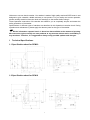
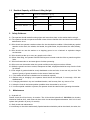
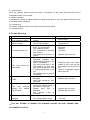
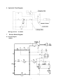
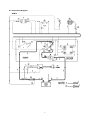
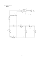
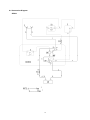
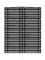
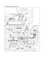
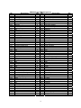
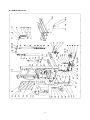
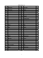
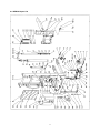
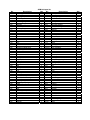
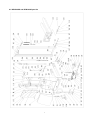
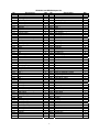
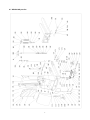
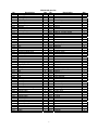
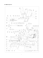
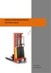
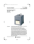
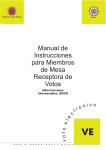
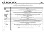
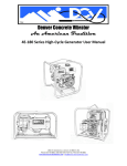
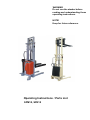
WARNING Do not use the stacker before reading and understanding these operating instructions. NOTE! Keep for future reference. Operating Instructions / Parts List SPM10, SPN10 Welcome to use our electric stacker. Your stacker is made of high quality steel and SPED mast. It was designed to give a durable, reliable and easy to use product. For your safety and correct operation, please carefully read this instruction book and warnings on the stacker before using it. These Operation Instructions of the stacker are edited for you to completely acquire and master the safety operations of the stacker. Specifications of different types of stackers are described in this Operation Instruction book. During operation and maintenance, please apply the relevant parts for the type of the stacker. All the information reported herein is based on data available at the moment of printing. We reserve the right to modify our own products at any moment without notice and liability in any sanctions. Therefore, it is suggested to always verify possible updates and changes. 1 Technical Specifications 1.1 Specification sheet for SPM10 1.2 Specification sheet for SPN10 1 Model of manufacture 1.3 Drive: (electric-battery or mains,diesel,petrol,fuel gas,manual) manual manual manual 1.4 Type of operation (hand,pedestrian,standing,seated,order picker) pedestrian pedestrian pedestrian 1.5 Load capacity / rated load Q (kg) 1000 1000 1000 1.6 Load centre distance c (mm) 600 600 600 1.9 Wheelbase y (mm) 1160 1160 1160 2.1 Weight (including battery) kg 410 475 495 3.1 Types (solid rubber,superelastic,nylon, polyurethane) Nylon/PU Nylon/PU Nylon/PU 3.2 Type size,front mm 180x50 180x50 180x50 3.3 Type size, rear mm 74x70 74x70 74x70 3.5 Wheels,number front/rear 2/4 2/4 2/4 3.6 Track width, front b10 (mm) 658 658 658 3.7 Track width, rear b11 (mm) 390/490 390/490 390/490 4.2 Lowered mast height h1 (mm) 1980 1830 2080 4.4 Lift height h3 (mm) 1600 2500 3000 4.5 Extended mast height h4 (mm) 1980 3070 3570 4.9 Height of handle min./max. h14 (mm) 790/1156 790/1156 790/1156 4.15 Fork height lowered h13 (mm) 85 85 85 4.19 Overall length L1 (mm) 1720/1570 1720/1580 1720/1580 4.20 Length to face of forks L2 (mm) 610/670 610/670 610/670 4.21 Overall width b1 (mm) 762 762 762 4.22 Fork dimensions s/e/L (mm) 4.25 Width over forks b5 (mm) 60/180/1100 60/150/900 570 330~640 60/180/1100 60/150/900 570 330~640 60/180/1100 60/150/900 570 330~640 4.33 Aisle width for pallets 1000×1200 crossways Ast (mm) 2145 2145 2145 4.34 Aisle width for pallets 800×1200 lengthways Ast (mm) 2175 2175 2175 4.35 Turning radius Wa (mm) 1280 1280 1280 Performance 5.2 Lift speed ,laden/unladen mm/s 90/140 90/140 90/140 5.3 Lowering speed ,laden/unladen mm/s 120/100 120/100 120/100 5.11 Parking brake manual manual manual 6.2 Lift motor rating at S3 15% kw 1.5 1.5 1.5 6.4 Battery voltage ,nominal capacity K5 V/Ah 12/150 12/150 12/150 6.5 Battery weight kg 45 45 45 Basic Dimensions Wheels Chassis Weight Characteristics 1.2 E-Motor SPM10 Technical Data SPM1016 2 SPM1025 SPM1030 Model of manufacture 1.3 Drive: (electric-battery or mains,diesel,petrol,fuel gas,manual) manual manual manual 1.4 Type of operation (hand,pedestrian,standing,seated,order picker) pedestrian pedestrian pedestrian 1.5 Load capacity / rated load Q (kg) 1000 1000 1000 1.6 Load centre distance c (mm) 600 600 600 1.9 Wheelbase y (mm) 1180 1180 1180 2.1 Weight (including battery) kg 396 443 466 3.1 Types (solid rubber,superelastic,nylon, polyurethane) Nylon/PU Nylon/PU Nylon/PU 3.2 Type size,front mm 180x50 180x50 180x50 3.3 Type size, rear mm 74x70 74x70 74x70 3.5 Wheels,number front/rear 2/4 2/4 2/4 3.6 Track width, front b10 (mm) 658 658 658 3.7 Track width, rear b11 (mm) 390/490 390/490 390/490 4.2 Lowered mast height h1 (mm) 1980 1830 2080 4.4 Lift height h3 (mm) 1600 2500 3000 4.5 Extended mast height h4 (mm) 1980 3070 3570 4.9 Height of handle min./max. h14 (mm) 770/1153 770/1153 770/1153 4.15 Fork height lowered h13 (mm) 85 85 85 4.19 Overall length L1 (mm) 1720/1570 1720/1580 1720/1580 4.20 Length to face of forks L2 (mm) 610/670 610/670 610/670 4.21 Overall width b1 (mm) 762 762 762 4.22 Fork dimensions s/e/L (mm) 4.25 Width over forks b5 (mm) 60/160/1100 60/150/900 550 330~640 60/160/1100 60/150/900 550 330~640 60/160/1100 60/150/900 550 330~640 4.33 Aisle width for pallets 1000×1200 crossways Ast (mm) 2145 2145 2145 4.34 Aisle width for pallets 800×1200 lengthways Ast (mm) 2175 2175 2175 4.35 Turning radius Wa (mm) 1280 1280 1280 Performance 5.2 Lift speed ,laden/unladen mm/s 90/140 90/140 90/140 5.3 Lowering speed ,laden/unladen mm/s 120/100 120/100 120/100 5.11 Parking brake manual manual manual 6.2 Lift motor rating at S3 15% kw 1.5 1.5 1.5 6.4 Battery voltage ,nominal capacity K5 V/Ah 12/150 12/150 12/150 6.5 Battery weight kg 45 45 45 Basic Dimensions Wheels Chassis Weight Characteristics 1.2 E-Motor SPN10 Technical Data SPN1016 3 SPN1025 SPN1030 1.3 Residual Capacity at Different Lifting Height Up to h3 mm ACTUAL CAPACITY ( Q ) kg 1500 1000 500 2500 1000 400 3000 600 300 Load centre distance ( C ) 600 800 mm 2 Safety Guidance 2.1 The operator should read all warning signs and instructions here on the stacker before using it. 2.2 The operator should not operate a stacker unless s/he are familiar with it and have been trained or authorized to do so. 2.3 S/he should not operate a stacker unless s/he has checked its condition. S/he should pay special attention to the chain, the wheels, the handle, the guide frame, the pilot wheel, the mast, battery, etc. 2.4 S/he should not use the stacker on a slopping ground or on a barbaric or explosive danger environment. 2.5 S/he should not take up or carry any people on the forks. 2.6 When forks lifting, the operator should forbid anyone to stand under the forks or pass through the forks. 2.7 S/he had better take on and wear gloves for labor protecting. 2.8 S/he not move the stacker when the goods are lifted to the height more than 300mm. 2.9 While the goods have been carried, transported or lifted, all people should be away from the forks for 600mm. 2.10 The weight of goods should be evenly distributed on the two forks, do not use only one fork. The center of gravity of goods should be in the center of both two forks. 2.11 The stacker should not be loaded over its maximum capacity. 2.12 Before using or charging it, the operator should check the cell liquid, if not enough, full it with distilled water. 2.13 Charging should be in dry and ventilated location, and far away from any source of fire. 2.14 Keep the forks in the lowest position possible when the stacker is not in use. 2.15 At other special condition or places, the operator should be careful when operating the stacker. 3 Maintenance 3.1 Hydraulic oil Please check the oil level every six months. The oil should be hydraulic oil: ISO VG32, its viscosity should be 32cSt at 40oC, total volume is about 4.0lt. Use at the temperature between -20oC~50 oC and replace the hydraulic oil (every 12 months). 3.2 Daily check and maintenance It is necessary to check the stacker daily. Special attention should be paid to the wheels, the axles, the 4 thread and the rags, etc., it may block the wheels, the forks and the mast, the chain, the battery should be checked, too. The forks should be unloaded and lowered in the lowest position when the job is over. 3.3 Lubrication The operator should use motor oil or grease to lubricate all movable parts. 3.4 Maintenance of battery: Keep all the screw caps on each cell battery dry and clean. Each connecting terminal and cable terminal should be tightened and painted with clean grease. The exposed connecting terminal and connecting rod of battery should be covered with anti-slip insulated cover. 3.5 Recharging the battery fully and carrying out usual battery maintenance. Maintain charging the battery every third month and check the fluid level. 4 How to Charge Storage Battery 4.1 4.2 4.3 4.4 Charge storage battery when its voltage is less than 10 Volt. Please check the battery liquid before charging, if it is not enough, add some distilled water. The charging environment should be ventilated and far away from any possible source of fire. If the stacker was not in use for a long time, it should be charged for not less than two hours every week. 4.5 The voltage on the indicator should not be over 15 Volt when charging. 4.6 Do not use the stacker during charging. 5 Control Panel SPM10 SPN10 5 5.1 Urgent button When the operator presses down this switch, it will switch off the power, and then s/he turns it clockwise to switch on the power. 5.2 Battery indicator It indicates the voltage of battery. When its voltage is less than 10 Volt, the operator should not use this stacker before charging it. 5.3 Control stick This stick controls the forks to move down and up to lower and lift. 5.4 Charger socket 6 Trouble Shooting Trouble The forks can not be lifted 1 to the maximum height The forks can not be lifted 2 (Motor is rotary) No 3 The motor cannot run. 4 The forks cannot be descended. 5 Leaks 6 7 The forks descend without the release valve worked. The battery cannot be charged △,! DO Clause The hydraulic oil is not enough Without hydraulic oil The oil has impurities The urgent switch is pressed down, cut off the power The voltage is too low The connectors of electrical wire is loose The contactor of DC motor is broken The piston rod or mast is deformed resulting from partial loading slanting to one side or over-loading The forks were kept in the high position for long time with piston rod bared to arise in rusting and jamming of the rod The release valve of pump is not opened Sealing parts worn or damaged Some part cracked or worn into small The impurities in the oil causes the release valve to be unable to close tight Sealing parts worn or damaged The release valve is damaged Battery is broken The charging plug is loose Fixing Methods Pour in the oil Fill in the oil Change the oil Turn it clockwise, switch on the power Charge it Turn it firm Replace with a new one Replace with a new one Keep the forks in the lowest position if not in use and pay more attention to lubricate the rod Check it, if damaged, replace with a new one Replace with new ones Replace with new ones Change the oil Replace with new ones Replace with a new one Replace with a new one Turn it firm NOT ATTEMP TO REPAIR THE STACKER UNLESS YOU ARE TRAINED AND AUTHORIZED TO DO SO. 6 6 Hydraulic Flow Diagram Woring pressure 7 P=122Bar Electric Wires Diagram 8.1 Circuit Diagram SPM10 7 8.2 Connection Diagram SPM10 8 8.3 Circuit Diagram SPN10 9 8.4 Connection Diagram SPN10 10 8 Parts List 9.1 SPM1025G and SPM1030G part list 11 No. 101 102 103 104 105 106 107 108 109 110 111 112 113 114 115 116 117 118 119 120 121 122 123 124 125 126 127 128 129 130 131 132 133 134 135 136 137 138 139 140 141 142 143 144 145 146 147 148 149 150 151 152 153 154 Description Inner Mast Locking Ring Bearing Roller For Chain Locking Ring Screw Locking Ring Bearing Roller Locking Ring Bolt Bolt Crutch of Idler Pulley Shaft Idler Pulley Locking Ring Mast Hoop Nut Bolt Nut Protecting Meshwork Protecting Washer Washer Bolt Handle Cover Charger Urgent Switch Pump Station Voltage Meter Bolt Bolt Battery Bolt Cap Bearing Bearing Seat of Wheel Draw-Bar for Turning Gas spring Locking Ring Seat of gas spring Hoop Bolt Shaft Bolt Shaft Seat of Draw-Bar Bolt Washer Washer Chain Washer SPM1025G and SPM1030G part list Qty. No. Description 1 155 Washer 2 156 Nut 2 157 Foot Plate 2 158 Locking Ring 2 159 Shaft 1 160 Brake 8 161 Spring 8 162 Bolt 8 163 Sprocket Wheel 8 164 Seat of Turning Wheel 2 165 Big Wheel 4 166 Bearing 2 167 Shaft of Wheel 2 168 Washer 2 169 Locking Nut 2 170 Bolt 1 171 Loading Roller 1 172 Bearing 3 173 Washer 1 174 Shaft 2 175 Linking Plate 1 176 Elastic Pin 4 180 Fork Carriage 4 181 Nut 4 182 Bolt 2 183 Pin 1 184 Cotter pin 1 185 Chain 1 186 O-Ring 1 187 Body of Adjusting Valve 1 188 Adjusting Bolt 4 189 Spring 4 190 Spindle of Valve 1 191 Nut 2 192 Seal Washer 2 193 Elbow Bend 3 194 Vitta 3 195 Elbow Bend 1 196 Earthen Pipe 1 197 Sleeve 1 198 Dust Ring 1 199 Cover 1 200 Piston Rod 1 201 Piston 2 202 O-Ring 1 203 O-Ring 1 204 Seal 1 205 Washer 1 206 Elastic Washer 1 207 Nut 2 208 Connect shank 1 209 Fixed Plank 1 210 Round cover 1 12 Qty. 1 1 1 1 1 1 1 1 2 1 2 4 2 4 2 2 4 8 8 4 4 8 1 4 2 4 8 2 1 1 1 1 1 1 1 1 1 1 1 1 1 1 1 1 2 1 1 1 1 1 1 1 1 9.2 SPM1025 and SPM1030 parts list 13 No. 101 102 103 104 105 106 107 108 109 110 111 112 113 114 115 116 117Y 118 119 120 121 122 123 124 125 126 127 128 129 130 131 132 133 134 135 136 137 138 139 140 141 142 143 144 145 146 147 148 149 150 151 152 153 154 155 Description Inner Mast Locking Ring Bearing Roller For Chain Locking Ring Screw Locking Ring Bearing Roller Locking Ring Bolt Bolt Crutch of Idler Pulley Shaft Idler Pulley Locking Ring Mast Hoop Nut Bolt Nut Protecting Meshwork Protecting Washer Washer Bolt Handle Cover Charger Urgent Switch Pump Station Voltage Meter Bolt Bolt Battery Bolt Cap Bearing Bearing Seat of Wheel Draw-Bar for Turning Gas spring Locking Ring Seat of gas spring Hoop Bolt Shaft Bolt Shaft Seat of Draw-Bar Bolt Washer Washer Chain Washer Washer SPM1025 and SPM1030 part list Qty. No. Description 1 156 Nut 2 157 Foot Plate 2 158 Locking Ring 2 159 Shaft 2 160 Brake 1 161 Spring 8 162 Bolt 8 163 Sprocket Wheel 8 164 Seat of Turning Wheel 8 165 Big Wheel 2 166 Bearing 4 167 Shaft of Wheel 2 168 Washer 2 169 Locking Nut 2 170 Bolt 2 171 Loading Roller 1 172 Bearing 1 173 Washer 3 174 Shaft 1 175 Linking Plate 2 176 Elastic Pin 1 180Y Fork Carriage 4 181 Nut 4 182 Bolt 4 183 Pin 2 184 Cotter pin 1 185 Chain 1 186 O-Ring 1 187 Body of Adjusting Valve 1 188 Adjusting Bolt 1 189 Spring 4 190 Spindle of Valve 4 191 Nut 1 192 Seal Washer 2 193 Elbow Bend 2 194 Vitta 3 195 Elbow Bend 3 196 Earthen Pipe 1 197 Sleeve 1 198 Dust Ring 1 199 Cover 1 200 Piston Rod 1 201 Piston 1 202 O-Ring 2 203 O-Ring 1 204 Seal 1 205 Washer 1 206 Elastic Washer 1 207 Nut 1 208 Connect shank 2 209 Fixed Plank 1 210 Round cover 1 211Y Retaining ring 1 212Y Long shaft 1 213Y Fork 14 Qty. 1 1 1 1 1 1 1 2 1 2 4 2 4 2 2 4 8 8 4 4 8 1 4 2 4 8 2 1 1 1 1 1 1 1 1 1 1 1 1 1 1 1 1 2 1 1 1 1 1 1 1 1 2 1 2 9.3 SPM1016G part list 15 No. 101S 102 103 104 105 106S 107 108 109 110 111 112 113 114 115 116 117S 118 119 120 121 122 123 124 125 126 127 128 129 130 131 132 133 134 135 136 137 138 139 140 141 142 143 144 145 146 147 148 149 150 151 152 153 154 155 Description Holding plate Locking Ring Bearing Roller For Chain Locking Ring Retaining ring Locking Ring Bearing Roller Locking Ring Mast Hoop Nut Bolt Nut Protecting Meshwork Protecting Washer Washer Bolt Handle Cover Charger Urgent Switch Pump Station Voltage Meter Bolt Bolt Battery Bolt Cap Bearing Bearing Seat of Wheel Draw-Bar for Turning Gas spring Locking Ring Seat of gas spring Hoop Bolt Shaft Bolt Shaft Seat of Draw-Bar Bolt Washer Washer Chain Washer Washer SPM1016G part list Qty. No. Description 1 156 Nut 2 157 Foot Plate 2 158 Locking Ring 2 159 Shaft 2 160 Brake 1 161 Spring 4 162 Bolt 4 163 Sprocket Wheel 4 164 Seat of Turning Wheel 4 165 Big Wheel 166 Bearing 167 Shaft of Wheel 168 Washer 169 Locking Nut 170 Bolt 171 Loading Roller 1 172 Bearing 1 173 Washer 3 174 Shaft 1 175 Linking Plate 2 176 Elastic Pin 1 180S Fork Carriage 4 181 Nut 4 182 Bolt 4 183 Pin 2 184 Cotter pin 1 185 Chain 1 186 O-Ring 1 187 Body of Adjusting Valve 1 188 Adjusting Bolt 1 189 Spring 4 190 Spindle of Valve 4 191 Nut 1 192 Seal Washer 2 193 Elbow Bend 2 194 Vitta 3 195 Elbow Bend 3 196 Earthen Pipe 1 197 Sleeve 1 198 Dust Ring 1 199 Cover 1 200 Piston Rod 1 201 Piston 1 202 O-Ring 2 203 O-Ring 1 204 Seal 1 205 Washer 1 206 Elastic Washer 1 207 Nut 1 208 2 209 Fixed Plank 1 210 Round cover 1 1 1 16 Qty. 1 1 1 1 1 1 1 2 1 2 4 2 4 2 2 4 8 8 4 4 8 1 4 2 4 8 2 1 1 1 1 1 1 1 1 1 1 1 1 1 1 1 1 2 1 1 1 1 1 1 1 9.4 SPM1016 part list 17 No. 101S 102 103 104 105 106S 107 108 109 110 111 112 113 114 115 116 117YS 118 119 120 121 122 123 124 125 126 127 128 129 130 131 132 133 134 135 136 137 138 139 140 141 142 143 144 145 146 147 148 149 150 151 152 153 154 155 Description Holding plate Locking Ring Bearing Roller For Chain Locking Ring Retaining ring Locking Ring Bearing Roller Locking Ring Mast Hoop Nut Bolt Nut Protecting Meshwork Protecting Washer Washer Bolt Handle Cover Charger Urgent Switch Pump Station Voltage Meter Bolt Bolt Battery Bolt Cap Bearing Bearing Seat of Wheel Draw-Bar for Turning Gas spring Locking Ring Seat of gas spring Hoop Bolt Shaft Bolt Shaft Seat of Draw-Bar Bolt Washer Washer Chain Washer Washer SPM1016 part list Qty. No. 1 156 2 157 2 158 2 159 2 160 1 161 4 162 4 163 4 164 4 165 166 167 168 169 170 171 1 172 1 173 3 174 1 175 2 176 1 180YS 4 181 4 182 4 183 2 184 1 185 1 186 1 187 1 188 1 189 4 190 4 191 1 192 2 193 2 194 3 195 3 196 1 197 1 198 1 199 1 200 1 201 1 202 2 203 1 204 1 205 1 206 1 207 1 208 2 209 1 210 1 211Y 1 212Y 1 213Y Description Nut Foot Plate Locking Ring Shaft Brake Spring Bolt Sprocket Wheel Seat of Turning Wheel Big Wheel Bearing Shaft of Wheel Washer Locking Nut Bolt Loading Roller Bearing Washer Shaft Linking Plate Elastic Pin Fork Carriage Nut Bolt Pin Cotter pin Chain O-Ring Body of Adjusting Valve Adjusting Bolt Spring Spindle of Valve Nut Seal Washer Elbow Bend Vitta Elbow Bend Earthen Pipe Sleeve Dust Ring Cover Piston Rod Piston O-Ring O-Ring Seal Washer Elastic Washer Nut Fixed Plank Round cover Retaining ring Long shaft Fork Qty. 1 1 1 1 1 1 1 2 1 2 4 2 4 2 2 4 8 8 4 4 8 1 4 2 4 8 2 1 1 1 1 1 1 1 1 1 1 1 1 1 1 1 1 2 1 1 1 1 1 1 1 2 1 2 9.5 SPN1025G and SPN1030G part list 1 No. 101A 102 103 104 105 106 107 108 109 109A 110 111 112 113 114 115 116 117A 118 119 120 121 122 123 124 125 126 127 128 129 130 131 132 133 134 135 136 137 137A 138 138A 139 140 141 142 143 144 145 146 147 148 149 150 151 152 153 SPN1025G and SPN1030G part list Description Qty. No. Description Inner Mast 1 154 Washer Locking Ring 2 155 Washer Bearing 2 156 Nut Roller For Chain 2 157 Foot Plate Locking Ring 2 158 Locking Ring Screw 1 159 Shaft Locking Ring 8 160 Brake Bearing 8 161 Spring Roller 4 162 Bolt Roller 4 163 Sprocket Wheel Locking Ring 8 164 Seat of Turning Wheel Bolt 2 165 Big Wheel Bolt 4 166 Bearing Crutch of Idler Pulley 2 167 Shaft of Wheel Shaft 2 168 Washer Idler Pulley 2 169 Locking Nut Locking Ring 2 170 Bolt Mast 1 171 Loading Roller Hoop 1 172 Bearing Nut 3 173 Washer Bolt 1 174 Shaft Nut 2 175 Linking Plate Protecting Meshwork 1 176 Elastic Pin Protecting Washer 4 180 Fork Carriage Washer 4 181 Nut Bolt 4 182 Bolt Handle 2 183 Pin Cover 1 184 Cotter pin Charging Plug 1 185 Chain Urgent Switch 1 186 O-Ring Pump Station 1 187 Body of Adjusting Valve Voltage Meter 1 188 Adjusting Bolt Nut 4 189 Spring Bolt 6 190 Spindle of Valve Battery 1 191 Nut Bolt 2 192 Seal Washer Cap 2 193 Elbow Bend Bearing 1 194 Vitta Bearing 2 195 Elbow Bend Bearing 1 196 Earthen Pipe Bearing 2 197 Sleeve Seat of Wheel 1 198 Dust Ring Draw-Bar for Turning 1 199 Cover Gas spring 1 200 Piston Rod Locking Ring 2 201 Piston Washer 2 202 O-Ring Shaft 1 203 O-Ring Locking Ring 2 204 Seal Shaft 1 205 Washer Locking Ring 2 206 Elastic Washer Shaft 1 207 Nut Seat of Draw-Bar 1 208 Connect shank Turning Shaft 1 209 Fixed Box Washer 2 210 Side mat Washer 1 211 Washer Chain 1 2 Qty. 1 1 1 1 1 1 1 1 1 2 1 2 4 2 4 2 2 4 8 8 4 4 8 1 4 2 4 8 2 1 1 1 1 1 1 1 1 1 1 1 1 1 1 1 1 2 1 1 1 1 1 1 1 8 8 9.6 SPN1025 and SPN1030 part list 3 No. 101 102 103 104 105 106 107 108 109 109A 110 111 112 113 114 115 116 117 118 119 120 121 122 123 124 125 126 127 128 129 130 131 132 133 134 135 136 137 137A 138 138A 139 140 141 142 143 144 145 146 147 148 149 150 151 152 153 154 Description Inner Mast Locking Ring Bearing Roller For Chain Locking Ring Screw Locking Ring Bearing Roller Roller Locking Ring Bolt Bolt Crutch of Idler Pulley Shaft Idler Pulley Locking Ring Mast Hoop Nut Bolt Nut Protecting Meshwork Protecting Washer Washer Bolt Handle Cover Charging Plug Urgent Switch Pump Station Voltage Meter Nut Bolt Battery Bolt Cap Bearing Bearing Bearing Bearing Seat of Wheel Draw-Bar for Turning Gas spring Locking Ring Washer Shaft Locking Ring Shaft Locking Ring Shaft Seat of Draw-Bar Turning Shaft Washer Washer Chain Washer SPN1025 and SPN1030 part list Qty. No. Description 1 155 Washer 2 156 Nut 2 157 Foot Plate 2 158 Locking Ring 2 159 Shaft 1 160 Brake 8 161 Spring 8 162 Bolt 4 163 Sprocket Wheel 4 164 Seat of Turning Wheel 8 165 Big Wheel 2 166 Bearing 4 167 Shaft of Wheel 2 168 Washer 2 169 Locking Nut 2 170 Bolt 2 171 Loading Roller 1 172 Bearing 1 173 Washer 3 174 Shaft 1 175 Linking Plate 2 176 Elastic Pin 1 177 Fork Carriage 4 178 Locking Ring 4 179 Long Axle 4 180Y Fork 2 181 Nut 1 182 Bolt 1 183 Pin 1 184 Cotter pin 1 185 Chain 1 186 O-Ring 4 187 Body of Adjusting Valve 6 188 Adjusting Bolt 1 189 Spring 2 190 Spindle of Valve 2 191 Nut 1 192 Seal Washer 2 193 Elbow Bend 1 194 Vitta 2 195 Elbow Bend 1 196 Earthen Pipe 1 197 Sleeve 1 198 Dust Ring 2 199 Cover 2 200 Piston Rod 1 201 Piston 2 202 O-Ring 1 203 O-Ring 2 204 Seal 1 205 Washer 1 206 Elastic Washer 1 207 Nut 2 208 Connect shank 1 209 Fixed Box 1 210 Side mat 1 211 Washer 4 Qty. 1 1 1 1 1 1 1 1 2 1 2 4 2 4 2 2 4 8 8 4 4 8 1 2 1 2 4 2 4 8 2 1 1 1 1 1 1 1 1 1 1 1 1 1 1 1 1 2 1 1 1 1 1 1 1 8 8 9.7 SPN1016G part list 5 No. 101S 102 103 104 105 106 107 108 109 110 111 112 113 114 115 116 117S 118 119 120 121 122 123 124 125 126 127 128 129 130 131 132 133 134 135 136 137 137A 138 138A 139 140 141 142 143 144 145 146 147 148 149 150 151 152 153 Description Holding plate Locking Ring Bearing Roller For Chain Locking Ring Screw Locking Ring Bearing Roller Locking Ring Mast Hoop Nut Bolt Nut Protecting Meshwork Protecting Washer Washer Bolt Handle Cover Charging Plug Urgent Switch Pump Station Voltage Meter Nut Bolt Battery Bolt Cap Bearing Bearing Bearing Bearing Seat of Wheel Draw-Bar for Turning Gas spring Locking Ring Washer Shaft Locking Ring Shaft Locking Ring Shaft Seat of Draw-Bar Turning Shaft Washer Washer Chain SPN1016G part list Qty. No. Description 1 154 Washer 2 155 Washer 2 156 Nut 2 157 Foot Plate 2 158 Locking Ring 1 159 Shaft 4 160 Brake 4 161 Spring 4 162 Bolt 4 163 Sprocket Wheel 164 Seat of Turning Wheel 165 Big Wheel 166 Bearing 167 Shaft of Wheel 168 Washer 169 Locking Nut 1 170 Bolt 1 171 Loading Roller 3 172 Bearing 1 173 Washer 2 174 Shaft 1 175 Linking Plate 4 176 Elastic Pin 4 180S Fork Carriage 4 181 Nut 2 182 Bolt 1 183 Pin 1 184 Cotter pin 1 185 Chain 1 186 O-Ring 1 187 Body of Adjusting Valve 4 188 Adjusting Bolt 6 189 Spring 1 190 Spindle of Valve 2 191 Nut 2 192 Seal Washer 1 193 Elbow Bend 2 194 Vitta 1 195 Elbow Bend 2 196 Earthen Pipe 1 197 Sleeve 1 198 Dust Ring 1 199 Cover 2 200 Piston Rod 2 201 Piston 1 202 O-Ring 2 203 O-Ring 1 204 Seal 2 205 Washer 1 206 Elastic Washer 1 207 Nut 1 208 2 209 Fixed Box 1 210 Side mat 1 211 Washer 6 Qty. 1 1 1 1 1 1 1 1 1 2 1 2 4 2 4 2 2 4 8 8 4 4 8 1 4 2 4 8 2 1 1 1 1 1 1 1 1 1 1 1 1 1 1 1 1 2 1 1 1 1 1 1 4 4 9.8 SPN1016 part list 7 No. 101S 102 103 104 105 106 107 108 109 110 111 112 113 114 115 116 117YS 118 119 120 121 122 123 124 125 126 127 128 129 130 131 132 133 134 135 136 137 137A 138 138A 139 140 141 142 143 144 145 146 147 148 149 150 151 152 153 154 155 Description Holding plate Locking Ring Bearing Roller For Chain Locking Ring Screw Locking Ring Bearing Roller Locking Ring Mast Hoop Nut Bolt Nut Protecting Meshwork Protecting Washer Washer Bolt Handle Cover Charging Plug Urgent Switch Pump Station Voltage Meter Nut Bolt Battery Bolt Cap Bearing Bearing Bearing Bearing Seat of Wheel Draw-Bar for Turning Gas spring Locking Ring Washer Shaft Locking Ring Shaft Locking Ring Shaft Seat of Draw-Bar Turning Shaft Washer Washer Chain Washer Washer SPN1016 part list Qty. No. Description 1 156 Nut 2 157 Foot Plate 2 158 Locking Ring 2 159 Shaft 2 160 Brake 1 161 Spring 4 162 Bolt 4 163 Sprocket Wheel 4 164 Seat of Turning Wheel 4 165 Big Wheel 166 Bearing 167 Shaft of Wheel 168 Washer 169 Locking Nut 170 Bolt 171 Loading Roller 1 172 Bearing 1 173 Washer 3 174 Shaft 1 175 Linking Plate 2 176 Elastic Pin 1 177S Fork Carriage 4 178 Locking Ring 4 179 Long Axle 4 180S Fork 2 181 Nut 1 182 Bolt 1 183 Pin 1 184 Cotter pin 1 185 Chain 1 186 O-Ring 4 187 Body of Adjusting Valve 6 188 Adjusting Bolt 1 189 Spring 2 190 Spindle of Valve 2 191 Nut 1 192 Seal Washer 2 193 Elbow Bend 1 194 Vitta 2 195 Elbow Bend 1 196 Earthen Pipe 1 197 Sleeve 1 198 Dust Ring 2 199 Cover 2 200 Piston Rod 1 201 Piston 2 202 O-Ring 1 203 O-Ring 2 204 Seal 1 205 Washer 1 206 Elastic Washer 1 207 Nut 2 208 1 209 Fixed Box 1 210 Side mat 1 211 Washer 1 8 Qty. 1 1 1 1 1 1 1 2 1 2 4 2 4 2 2 4 8 8 4 4 8 1 2 1 2 4 2 4 8 2 1 1 1 1 1 1 1 1 1 1 1 1 1 1 1 1 2 1 1 1 1 1 1 4 4