1
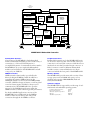
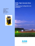
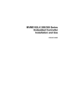
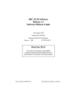
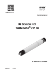
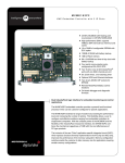
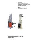
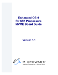
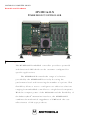
MOTOROLA COMPUTER GROUP
Board Level Products
MVME162LX
E MBEDDED C ONTROLLER
Advantages
The MVME162LX embedded controller provides a powerful
and functional CPU which can be customer-configured for
specific applications.
The MVME162LX extends the range of solutions
provided by the MVME162FX series by boosting the
performance level and increasing the number of options. This
flexibility allows a user to configure cost-effective solutions
ranging from embedded controllers to single-board computers.
With the compute power of the MC68040 and the flexibility of
the IndustryPack
®
mezzanine interface, the MVME162LX
combines the mechanical ruggedness of VME with the costeffectiveness of PC-type products.
Features
The Motorola Commitment
• Choice of processors:
Motorola Computer Group is committed to providing
best-in-class embedded computing solutions. The
MVME162LX series reinforces this commitment by providing
superior hardware, price performance and faithfulness to the
tenets of open computing: modularity, scalability, portability and
interoperability.
• 25 MHz or 32 MHz MC68040 enhanced 32-bit
microprocessor with 8KB of cache, and MMU
and FPU
• 25 MHz MC68LC040 enhanced 32-bit
microprocessor with 8KB of cache and MMU
• Optional VMEchip2 A32/D64 VMEbus
master/slave interface with system controller
function
Motorola Computer Group is ISO9001 registered, and provides
world class quality in manufacturing, engineering, sales, and
marketing.
• High-performance DMA, supports VMEbus D64
and local bus memory burst cycles
Ordering Information
• 4, 8, 16, or 32MB of shared DRAM, parity or
error checking and correction (ECC); expandable
to 64MB via expansion mezzanines
• 128KB of SRAM with battery backup
• Flash memory for on-board monitor/debugger for
user-specified requirements (1MB on MVME1622xx/3xx models, 2MB on 7xx/8xx models)
• 8K x 8 NVRAM and time-of-day clock with
battery backup
• Four serial communication ports, configured as
EIA-232-D DTE
• Two IndustryPack ports
• Six 32-bit timers (four without VMEbus) and
watchdog timer
• Optional SCSI bus interface with 32-bit local bus
burst DMA
• Optional Ethernet transceiver interface with 32-bit
local bus DMA
• Four 32-pin JEDEC sockets for EPROM and Flash
(models MVME162-2xx/3xx only; 7xx/8xx
models* have only two JEDEC sockets)
• Four-level requester, seven-level interrupter, and
seven-level interrupt handler for VMEbus
• Remote Reset/Abort/Status control functions
• On-board debugger and diagnostic firmware
*shown in photo
Part Number
Description
All models include 128KB SRAM with battery backup, Flash memory with MVME162BUG
installed, 8K x 8 NVRAM/TOD Clock, four serial ports, two IndustryPack ports, and timers.
25 MHz MC68LC040
MVME162-210y
MVME162-211y
MVME162-212y
MVME162-213y
MVME162-233y
MVME162-322y
MVME162-323y
MVME162-253y
4MB DRAM, no SCSI or Ethernet
4MB DRAM, SCSI only
4MB DRAM, Ethernet only
4MB DRAM, SCSI and Ethernet
4MB ECC DRAM, SCSI and Ethernet
8MB ECC DRAM, Ethernet only
8MB ECC DRAM, SCSI and Ethernet
16MB ECC DRAM, SCSI and Ethernet
25 MHz MC68040
MVME162-220y
MVME162-222y
MVME162-223y
MVME162-243y
MVME162-333y
MVME162-262y
MVME162-263y
MVME162-353y
4MB DRAM, no SCSI or Ethernet
4MB DRAM, Ethernet only
4MB DRAM, SCSI and Ethernet
4MB ECC DRAM, SCSI and Ethernet
8MB ECC DRAM, SCSI and Ethernet
16MB ECC DRAM, Ethernet only
16MB ECC DRAM, SCSI and Ethernet
32MB ECC DRAM, SCSI and Ethernet
32 MHz MC68040
MVME162-723y
MVME162-743y
MVME162-763y
MVME162-813y
MVME162-833y
MVME162-853y
MVME162-863y
4MB DRAM, SCSI and Ethernet
4MB ECC DRAM, SCSI and Ethernet
16MB ECC DRAM, SCSI and Ethernet
8MB DRAM, SCSI and Ethernet
8MB ECC DRAM, SCSI and Ethernet
32MB ECC DRAM, SCSI and Ethernet
16MB DRAM, SCSI and Ethernet
DRAM Expansion Memory
MEM162-202y
MEM162-203y
MEM162-204y
MEM162-207y
MEM162-208y
MEM162-209y
MEM162-210y
MEM162-211y
MEM162-212y
4MB (non-stacking)
16MB ECC (non-stacking)
16MB ECC (stacking)
4MB ECC (non-stacking)
4MB ECC (stacking)
8MB ECC (non-stacking)
8MB ECC (stacking)
32MB ECC (non-stacking)
32MB ECC (stacking)
Documentation
68-M162LXSET
68-1X7DS
User’s Manual set
Peripheral chipset manuals
Notes
1.
As denoted above, y indicates a major revision level; for example, “-210A.”
2.
Firmware source and object modules are available upon request.
3.
Non-stacking memory modules must be used as the terminal MVME162 memory
module, either alone or on top of a stacking module. A stacking memory module must
be used as the first MVME162 memory module and will accept one non-stacking
module installed on top of it.
4.
Documentation is also available on line at http://www.mcg.mot.com/literature.
VMEbus
A32/24:D64/32/16/08
Master/Slave
P1
P2
4 or 8MB Parity DRAM
4, 8, 16, 32MB ECC DRAM
Memory Array
Optional
FLASH
128K/2MB SRAM Memory
Array with Battery
VMEchip2
VMEbus
Interface
MC68040 or
MC68LC040
processor
MCchip
Battery-Backed
8KB RAM/Clock
IPchip
IndustryPack
2 Ports
Two or Four
32-pin EPROM
Sockets
Optional
85230 Serial I/O
Controllers
RJ-45 Serial port
Connectors
i82596CA
Ethernet
Controller
IP Ports
DB-15
Ethernet
53C710
SCSI
Coprocessor
68-Pin SCSI
Connector
MVME162LX Embedded Controller
IndustryPack Interface
Peripheral Interface
A key feature of the MVME162 is the IndustryPack
interface. IndustryPack modules provide a wide variety of
connectivity to “real-world” I/O. Expansion is
accomplished by means of a mezzanine board mounted to
the MVME162. Up to two single-wide IndustryPack
modules can be installed on the MVME162LX and still
occupy only one VME slot.
Peripheral I/O connections for the MVME162LX series
are located on the front panel of the module. Serial port
connection is via four RJ-45 connectors. SCSI devices are
interfaced via an industry-standard 68-pin connector. A
DB-15 connector is used for Ethernet. IndustryPack
modules connect to external I/O devices via 50-pin
connectors behind the front panel of the MVME162LX.
VMEbus Interface
Memory Options
VMEbus interface functionality is provided by the
Motorola-designed VMEchip2 ASIC. In addition to
controlling the system’s VMEbus functions, the
VMEchip2 includes a local bus to/from VMEbus DMA
controller, VME board support features, as well as global
control and status register (GCSR) for interprocessor
communications. The MVME162LX also provides
support for the VME D64 specification within the
VMEbus interface, further enhancing system performance.
The MVME162LX provides users with a variety of data
storage options such as DRAM with parity or error
checking and correction, EPROM/ROM, Flash and
battery-backed SRAM.
For deeply embedded applications, versions of the
MVME162LX are available without the VMEbus
interface. These versions have power and ground
connections through the P1 VMEbus connector.
Software Support
The MVME162LX is supported by a wide range of realtime kernels and embedded operating systems.
Lynx Real-Time Systems, Inc.:
Integrated Systems, Inc.:
Microware Systems Corporation:
Microtec:
Wind River Systems, Inc.:
LynxOS™
pSOS+™
OS-9®
VRTX32™
VxWorks®
Specifications
SCSI Bus
MVME162LX Embedded Controller
Controller:
Local Bus DMA:
Asynchronous:
Synchronous:
Processor
Microprocessor:
Clock Frequency:
MC68LC040
25 MHz
MC68040
25 MHz or 32 MHz
Ethernet
Controller:
Local bus DMA:
Memory
Dynamic RAM
Capacity:
Read Burst Mode:
Write Burst Mode:
Shared:
NCR 53C710
Yes, with local bus burst
5.0MB/s
10.0MB/s
4MB
8MB
4-1-1-1
4-2-2-2
3-2-2-2
3-2-2-2
VMEbus and local bus
ECC Dynamic RAM
Capacity:
Wait States:
Read Burst Mode:
Write Burst Mode:
Shared:
Static Ram
Capacity:
Read Burst Mode:
Write Burst Mode:
Parity:
Shared:
Battery Type:
Battery Life (approximate):
16MB
4-2-2-2
3-2-2-2
4, 8, 16 or 32 MB
3 read, 0 write
5-1-1-1
2-1-1-1
VMEbus and local bus
128KB
5-3-3-3
5-3-3-3
No
VMEbus and local bus
Lithium
1,371 days continuous backup at 25° C, 270
days at 70° C
82596CA
Yes
Power Requirements (no IP Modules)
+5V ± 5%:
+12V ± 5%:
Typical
3.5 A
—
–12V ± 5%:
100 mA
Asynchronous Serial Ports
Controller:
Number of Ports:
Configuration:
Async Baud Rate:
Sync Baud Rate:
85230
Four
EIA-232-D DTE (all four ports)
38.4Kbps max.
38.4Kbps max.
Board Size
Height:
Depth:
Front Panel Height:
Width:
233.4 mm (9.2 in.)
160.0 mm (6.3 in.)
261.8 mm (10.3 in.)
19.8 mm (0.8 in.)
Hardware Support
Multiprocessing Hardware Support:
ROM/EPROM (150ns)
Number of Sockets:
MVME162-2xx/3xx
MVME162-7xx/8xx
Capacity:
Access Cycles:
Four (512K x 16)
Two (512K x 16)
4MB
Six read, seven write
Flash (120ns)
Capacity:
MVME162-2xx/3xx
MVME162-7xx/8xx
Access Cycles:
1MB
2MB
Five read, six write
Demonstrated MTBF
Six 32-bit, 1 µsec resolution
8KB NVRAM; M48T08 (2xx/3xx) or
M48T58 (7xx/8xx)
Time-out generates Reset
Temperature:
Counters/Timers
Real-Time Timers/Counters:
TOD Clock Device:
Watchdog Timer:
VMEbus ANSI/VITA 1-1994 VME64 (IEEE STD 1014)
DTB Master:
DTB Slave:
Arbiter:
Interrupt Handler:
Interrupt Generator:
System Controller:
Location Monitor:
A16–A32; D08–D64, BLT, UAT + MBLT
A16–A32; D08–D64, BLT, UAT + MBLT
RR/PRI
IRQ 1–7
Any 1 of 7
Yes, jumperable
4, LMA32
IndustryPack Logic Interface
Data Width:
Interrupts:
DMA:
Clock Speed:
Module Types:
Transfer Rate-8 MHz:
16/32-bit
Two levels
Four channels
8 MHz (MVME162-2xx/3xx),
8 MHz and 32 MHz (MVME162-7xx/8xx)
Four single-high, two double-high
8MB/sec 16-bit; 16MB/sec 32-bit
Maximum
4.5 A
100 mA (max., with off-board LAN
transceiver)
—
Debug/Monitor:
Four mailbox interrupts, RMW, shared
RAM
MVME162FW, boot and diagnostics
Peripheral Connectors
Serial Ports:
Ethernet:
SCSI:
IndustryPack I/O:
Four RJ-45 connectors
DB-15
68-pin micro D high density
Access via two 50-pin connectors
Mean/90% Confidence:
190,509 hours/107,681 hours
Environmental
Altitude:
Humidity (NC):
Vibration:
Operating
0° C to +70° C,
forced air cooling exit air
5,000 m
5% to 90%
2 Gs RMS,
20–2000 Hz random
Nonoperating
–40° C to +85° C
15,000 m
5% to 90%
8 Gs RMS,
20–2000 Hz random
Safety
All printed wiring boards (PWBs) are manufactured with a flammability rating of
94V-0 by UL recognized manufacturers.
Electromagnetic Compatibility (EMC)
Intended for use in systems meeting the following regulations:
U.S.:
FCC Part 15, Subpart B, Class A (nonresidential)
Canada:
ICES-003, Class A (nonresidential)
This product was tested in a representative system to the following standards:
CE Mark per European EMC Directive 89/336/EEC with Amendments; Emissions:
EN55022 Class B; Immunity: EN50082-1
For more information, visit our World Wide Web site at http://www.mcg.mot.com
To call us dial 1-800-759-1107 in the U.S. and 512-434-1526 outside of the U.S.
Corporate headquarters address: Motorola Computer Group, 2900 S. Diablo Way, Tempe, AZ 85282
Copyright 1997 Motorola, Inc.
Data Sheet: 162LX-D4 4/99
Computer Group
Motorola and the Motorola logo are registered trademarks of Motorola, Inc. IndustryPack is a registered trademark of SBS GreenSpring Modular I/O, Inc. All other names, products, and/or services
mentioned may be trademarks or registered trademarks of their respective holders.
This data sheet identifies products, their specifications, and their characteristics, which may be suitable for certain applications. It does not constitute an offer to sell or a commitment of present or future
availability, and should not be relied upon to state the terms and conditions, including warranties and disclaimers thereof, on which Motorola may sell products. A prospective buyer should exercise its own
independent judgement to confirm the suitability of the products for particular applications. Motorola reserves the right to make changes, without notice, to any products or information herein which will, in
its sole discretion, improve reliability, function, or design. Motorola does not assume any liability arising out of the application or use of any product or circuit described herein; neither does it convey any
license under its patent or other intellectual property rights or under others. This disclaimer extends to any prospective buyer, and it includes Motorola’s licensee, licensee’s transferees, and licensee’s customers
and users. Availability of some of the products and services described herein may be restricted in some locations.