1
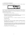
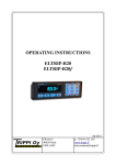
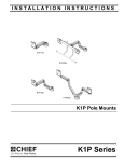
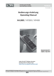
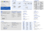
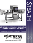
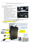
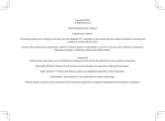
OPERATING INSTRUCTIONS
ELTRIP-65nk
ELTRIP-65nkl
ELTRIP-65nkc
ELTRIP-65nkb
Pilvitie 6
90620 Oulu
FINLAND
01/2013
p. +358 8 512 165
www.trippi.fi
[email protected]
Table of contents
1.Technical information.................................................................................................3
2.Introduction................................................................................................................4
3.Installation of Eltrip-65n............................................................................................5
3.1.Installation...........................................................................................................5
3.2.Installation of sensor and wiring.........................................................................5
3.3.Caution!...............................................................................................................6
4.Using Eltrip-65...........................................................................................................6
4.1.Settings................................................................................................................7
4.2.Distance calibration.............................................................................................7
4.3.Friction and temperature calibrations..................................................................8
4.4.Selecting counters................................................................................................9
4.5.Use of counters....................................................................................................9
4.6.Distance pre-set.................................................................................................10
4.7.Speed.................................................................................................................10
4.8.Temperature.......................................................................................................10
4.9.Friction measurement........................................................................................11
4.10.Brightness and turning off display...................................................................12
5.Computer connectivity.............................................................................................13
5.1.Bluetooth pairing...............................................................................................13
5.2.Sending friction results......................................................................................13
5.3.Data sending from meter...................................................................................13
5.4.Computer-controlled communication................................................................14
6.Problems?.................................................................................................................17
7.Declaration of Conformity........................................................................................18
8.Quick instructions.....................................................................................................20
2
1. TECHNICAL INFORMATION
KEYBOARD: 16 snap-action push buttons
FEATURES:
• 6 counters, of which 1 to 5 can be active at any time
• 1-metre display resolution
• Time for each counter (hours:minutes)
• Total-km calculator for each counter
• Speed with 0.1km/h resolution
• Road friction measurement
• Road temperature measurement (65nkl, 65nkc models)
• Computer connectivity (65nkc, 65nce models)
• Language selection
DISPLAY: Graphical display, 10mm number height, can be turned off
DIMENSIONS: 145x47x25mm (W x H x D)
WEIGHT: n. 150 g
OPERATING VOLTAGE: 10-30V
CURRENT CONSUMPTON:
• display enabled n. 100mA, display off n. 50mA
OPERATING TEMPERATURE RANGE: -30º - +60º C
FUSE: max 400 mA
SENSOR: various choices available
3
2. INTRODUCTION
We congratulate you for selecting reliable and dependable ELTRIP-meter.
This operating instruction booklet is there to instruct you on installation and
operation of your ELTRIP meter. Please read this instruction manual carefully for
instructions on meter installation, calibration and usage. This allows you to get most
out of your meter.
If you have problems with the meter, see chapter 6 of this manual. If this does not
help, contact us for further information. Do not try to repair the meter yourself, as
servicing the meter requires special skills and tools, and inproper handling of the
meter electronics may damage it. Warranty does not cover damage caused by
inproper use or servicing of the meter.
When your meter reaches end of its life, please return it to Trippi oy for
proper recycling. The return is free for you. If needed, contact Trippi Oy
for details.
4
3. INSTALLATION OF ELTRIP-65N
3.1. INSTALLATION
Install the meter so that you can easily reach it and it does not interfere with operating
of the vehicle. Avoid location where meter is exposed to direct sunlight or hot air
from heating system.
3.2. INSTALLATION OF SENSOR AND WIRING
Install sensor as described in external instructions.
It is recommended that meter is installed in continuous voltage.
NOTE: DANGER OF FIRE
If vehicle's main power switch is connected to negative (-) wire of battery and
you wish to connect meter to continuous power, contact the manufacturer for
detailed instructions. The negative supply (-) of the meter and meter housing are
connected within the meter. This may cause bypass of main power switch if
negative wire is connected past the main power switch.
Black wire: Connect to vehicle chassis (negative supply).
Red: Positive operating voltage 10 .. 30v, fused with max 400mA fast fuse. Can be
taked from fuse box of vehicle or other suitable location where it does not interfere
with normal operation of vehicle. Supply wire must be protected with small enough
fuse.
White: Positive (+) lead of sensor is connected to white wire, negative wire of sensor
to vehicle ground. If using vehicle's internal sensor only white wire is connected.
Some electronic systems may require external adapter.
Purple: +/- counting. If meter should reduce measured distance when vehicle is in
reverse, connect this to positive side of auxiliary reverse light. If reverse operation is
not necessary, connect to vehicle ground and meter will always count up.
Yellow: Brake detection. Typically connected to auxiliary brake light's positive
signal.
Temperature sensor: (65nkl, 65nkc, 65nkb models) Install sensor to front part of
vehicle, for example under the bumber. Connect the sensor wire to meter.
5
3.3. CAUTION!
Disconnect the meter during welding operations. Although meter is protected against
interference, welding may cause high voltages that breaks sensitive electrics.
Blown fuse may only be replaces with fuse of another type (max 400mA). Warranty
does not cover inproper installation of meter.
4. USING ELTRIP-65
Eltrip-65n has been designed to be easy to use in vehicle. All of the most frequent
operations can be used with only one key. Settings and other less ofter needed
features are activated with simultaneous press of two buttons. Following chapter
describes meter functions starting from post-installation calibrations.
Front panel and keyboard of Eltrip-65n
During normal operation a distance reading is shown on meter display, as above. This
is called main screen of meter, and most of the operations are initiated from this
mode. At upper left part of the screen the currently active counter is shown (here 1;
can be 1-6 or letter for special measurement modes) and on right is the currnet
reading. If a small downwards arrow is shown below counter number, the downcounting of counter 1 is active.
On lower left screen a sub-function of a counter is indicated (”Dist” for distance,
”Time” for time or ”Tot” for total-km counter).
At lower right the status of distance counters is shown; is counter has bright
background (here 1 and 3) the counter is active, and if background is dark the counter
is disabled (not currently counting).
6
4.1. SETTINGS
Settings can be opened by pressing OK and 3 at the same time at main screen.
Available settings vary based on the exact model of the meter.
Meter settings (OK + 3)
A specific setting can be selected with Next and Previous selections below the screen.
Setting is changed by pressing Select or OK keys. Settings menu is closed and active
settings stored by pressing CLR button. You can also change a specifig setting by
pressing indicated number key, for example Language can be changed by pressing 2
button.
The settings are:
• RS232 speed (65nkc,65nkb models). Set bit rate of computer connectivity.
Available settings are 1200, 9500 and 19200 bps. Other line parameters are
always 8 data bits, no parity and 1 stop bit.
• Language. This changes the language used in menus and setting screens.
Available selections are finnish, english and swedish.
4.2. DISTANCE CALIBRATION
Meter must be calibrated for distance measurement to be accurate. Calibration is done
on a straight road with where distance from a specific point to another is known
accurately.
Calibration is opened by pressing OK and 1 on meter main screen. If you know how
many impulses per kilometre meter produces, you can enter it directly with number
buttons.
Distance calibration screen
You can also select Measure -selection with keys below screen. Drive vehicle to start
point of a track of known length and select Measure. During the measurement
reading can be cleared with Reset selection. At the end of the track you can accept the
measured reading by pressing Accept. If the track is not exactly one kilometre in
length the reading must be corrected arithmetically.
For example: On a track of 500 metres 1742 pulses is measured. In this case reading
7
of pulses per kilometre is 1742x2 = 3484 pulses, which is then entered as calibration
factor.
After calibration verify measurement by driving the known track for a few times and
measuring its length by using meter counters.
4.3. FRICTION AND TEMPERATURE CALIBRATIONS
For measured friction reading to be reliable, meter must be calibrated to measure a
known reading at known environment, for example on calibration event or by using
known friction reference.
Setting the friction calibration
Friction calibration screen is opened by pressing OK and 8/F buttons at same time.
For friction measurement two readings are set: scaler and rolling constant. First the
scaler is set, then the rolling constant.
Scaler determines friction level and depending on vehicle and tires it generally is
between 400 and 700. Generally the better tires are, the lower value is set. At first
measurement set 500 and correct as needed. If meter measures too high friction
measurement, lower this value.
Rolling constant is set between 10 .. 100, on smaller cars typically 30 .. 50.
If meter has temperature measurement function, third value is temperature
measurement offset. This value is set so that in desired opering point – typically at 0
degrees Celcius – meter shows this value exactly. This value is typically around
172.0, but this may vary depending in meter and sensor. If meter measures too high
temperature, lower this value and vice versa.
8
4.4. SELECTING COUNTERS
Meter has six indenpendent counters, and each also has three sub-functions. Either
counter 1 or 2 is always enabled, and other of these two is always disabled. When
either of these is selected, meter automatically starts selected counter and stops the
other at same time.
Counter is selected by pressing number key 1-6. Counter selection always selects first
sub-counter (distance trip). Sub-counters (time and total-km) are selected by pressing
ALT button after selecting the counter.
Meter main screen with counter 1 distance shown
By holding number button 1-6 or HOLD-button down the currently shown reading of
counter is held until the button is released. During this time the counter still counts
normally, only the reading on the screen is not updated. After button is released the
normal running reading is restored. In 65nce-model when the button is pressed, on
left part of the screen also the currently active pulse input type is shown: ENC for
encoder, and P/R for pulse/reverse.
4.5. USE OF COUNTERS
Counters 1 and 2 are exclusive: When either of these is selected to the screen, the
selected counter is automatically started and the other is stopped.
Counters 3-6 are started by pressing
pressing
-button.
-button below the screen and stopped by
A counter is cleared (zeroed) by pressing CLR-button for approximately one second.
The counter is cleared so that if the vehicle is moving, the reading starts from the
exact position where vehicle was at the moment when CLR was pressed down.
If current sub-counter is distance or time, both of these are cleared. If total-km
counter is shown, only the total kilometres are cleared. Clearing counter 1 also
disables the down-counting if it were enabled.
9
4.6. DISTANCE PRE-SET
Counter 1 can be set to count up or down from given reading. Preset is done by
pressing HOLD and 1 buttons at same time.
Distance pre-set
Enter the desired start reading and select Down to start downcounting or Up to
normal up-counting. Cancel will abort setting and return to previous mode without
changing the previous counter 1 reading.
The down-counting will only affect counter 1. Other counters will still count
normally up even is down-counting is enabled. On the meter main screen the
downcounting indicator is a small downwards arrow that is shown below the counter
number at the left part of the screen.
When down-counting is enabled, counter 1 will count downwards when driving
forward and upwards when reversing.
4.7. SPEED
Speed reading is selected by pressing S/7 button. Currently active counters resume
operation normally on the background.
4.8. TEMPERATURE
If meter is equipped with temperature measurement, the temperature is selected on
screen by pressing 8/F. Letter T is then shown at the left part of screen. The meter
shows warning symbol instead of temperature reading, there is a problem with
temperature sensor or its connection. Temperature is shown as degrees Celcius.
Temperature reading
When temperature is shown on screen, meter is also ready for friction measurement.
See following chapter for details.
10
4.9. FRICTION MEASUREMENT
Friction measurement is selected by pressing 8/F button. Distance counters continue
to operate normally during friction measurement.
Friction measurement screen with friction result shown
If meter has no temperature measurement, screen shows letter F and two lines. If
meter is equipped with temperature measurement, the temperature is shown instead.
Either way meter is ready for friction measurement. Measurement can be restarted at
any time by pressing 8/F again.
The friction measurement is done as follows:
• Select straight and even part of road for measurements
• Important: Verify that measurement can be done safely. Make sure that there
are no one driving behind or ahead of you during measurement.
• Drive at even speed of 60km/h .
• Press down clutch, or in case of automatic transmission lift foot from
acceleretor pedal.
• Wait for two seconds
• Push brake pedal all the way down as quickly as possible, brake for
approximately two seconds and quickly release the brake. During braking
meter shows three lines on display.
• After braking meter shows four lines on display. Let vehicle roll freely (clutch
still down) until reading is shown on meter. With 65nkc and 65nkb-models the
measurement result can be sent to computer by pressing OK button at this time.
See chapter for XX for details on this.
• If needed, press 8/F to start measurement again.
11
4.10.
BRIGHTNESS AND TURNING OFF DISPLAY
If vehicle does not move for approx. 5 minutes the meter will automatically turn off
the display. When automatically turned off, the meter will automatically restore the
display when vehicle starts moving again. The display can also be restored by
pressing any button.
Display brightness can be changed by pressing ”lamp” ( ) -button below the screen.
By holding this button down for a second the meter display is turned off after this
button is released. When the button is being held the type and version information of
the meter is shown. When turned off manually the meter does not automatically turn
display back on and the screen must be restored by pressing any key.
All of the meter counters always continue to operate even when meter display is off.
12
5. COMPUTER CONNECTIVITY
Eltrip-65nkc and 65nkb models are equipped with computer connectivity option
which allows to send measurement results to computer manually or allows the
computer to control all the measurement functions of the meter.
Wired communications is done with RS-232 -compatible link. Link uses following
parameters:
Connector
RS232 D9 female
Bit rate:
1200, 9600 or 19200 bps (configurable on meter)
Parameters:
8 data bits, no parity, 1 stop bit
Flow control:
None
5.1. BLUETOOTH PAIRING
Eltrip-65nkb -models have additionally an internal BlueTooth adapter. Wired RS232communication can be used at same time with BlueTooth mode if needed.
Meter is visible for other BlueTooth devices only when in Settings-mode (see above).
To pair the meter with your device, put meter to this mode and do pairing from your
device as RFCOMM (virtual serial port) device. After pairing the BlueTooth-link can
be re-opened any time and all functions mentioned below can be used normally. For
details on performing pairing with your device, see the device's instructions.
PIN code for pairing is 1111.
5.2. SENDING FRICTION RESULTS
Friction measurement results can be sent to computer or other device by pressing OK
button when measurement result is shown on display. Meter sends the result as
NMEA-format message as follows:
$PTRPF,0000,0.5,0.352*6D<cr>
Message starts with start indicator $. After this follows message header, PTRPF. This
is then followed by road condition info (here 0000), temperature reading (here +0.5
degrees Celcius) and friction reading (0.352). This is followed by end character *,
after which follows two-digit checksum and carriage return character.
Checksum is calculated by taking exclusive or (XOR) operation of every character
between $ and * -characters, excluding these. If there is problem with temperature
sensor, temperature field is empty.
13
5.3. DATA SENDING FROM METER
Meter can be put to data link mode where user can manually send counter 1 reading
to computer at any time. Data link mode is entered by pressing OK and 6 at same
time at meter main screen.
Manual data link mode
Data link mode uses meter counter 1 only. Other counters remain their operaton
normally on background, but only counter 1 reading is shown on screen and can be
sent to computer.
Data link mode is closed by pressing Exit button for one second.
Meter buttons 0-6 function as code numbers that is attached to sent reading in format
<code>,<kkk.mmm><cr>. For example by pressing number 2 following message is
sent:
2,003.524<cr>
Continuous sending is enabled by pressing OK-key for two seconds. Display shows
”Continuous transmit” and reading of counter 1 is sent continuously in format
<kkk.mmm><cr> to computer. Continuous transmit can be stopped by pressing OKbutton again for two seconds, by sending a specific code with buttons 0-6 or by
exiting data link mode.
5.4. COMPUTER-CONTROLLED COMMUNICATION
Computer can control all the measurement functions of the meter by using simple
text-based protocol that is backwards compatible with protocol used by Eltrip-45nc.
Computer can always control the meter regardless of the current meter mode.
Command is sent from computer and meter responds. Commands always terminate
on <cr> (carriage return) character. Note that when using this protocol, meter
counters 1-6 are referred with indices 0-5.
All meter functions can also be used from meter keyboard when it is controlled by
computer.
Responses. Meter responds to commands with requested data or following
replies:
+<cr>
Command accepted
I<cr>
Invalid counter index
C<cr>
Unrecognized command
14
Read commands (n is counter index 0-5). These commands can be appended
with character c, for example A0c<cr>, in which case meter will continuously
send requested reading until next command is received.
An<cr>
Read distance counter n (e.g. A2<cr>). Reply is
kkk.mmm<cr>.
Bn<cr>
Read time counter n. Reply is hhh.mm<cr>
Dn<cr>
Read counter n total-km reading. Reply is nnnnn<cr>
Gn<cr>
Read distance counter n with 0.1 metre resolution.
Reply is kkk.mmmm<cr>
S0<cr>
Read speed. Reply is nnn.n<cr>
I0<cr>
Read calibration factor for pulse/reverse operation.
Reply is nnnnn<cr>
I1<cr>
Read calibration factor for encoder operation (only on
65nce). Reply is nnnnnn<cr>.
Counter control (n is counter index 0-5).
Cn<cr>
Clear distance and time of counter n
En<cr>
Clear total-km of counter n
On<cr>
(letter O) Start counter n. Note that with indices 0 or 1
(counter 1 or 2) the other of these is stopped.
Fn<cr>
Stop counter n.
Calibration
K0nnnn<cr>
Set calibration factor for normal (pulse/reverse)
operation.
K1nnnn<cr>
Set calibration factor for encoder operation (only
65nce-model)
Example:
Computer:
K03612<cr>
(set calibration 3612)
Eltrip:
+<cr>
Computer:
A8n<cr>
Eltrip:
I<cr>
Computer:
A2c<cr>
Eltrip:
492.525<cr>
Eltrip:
492.527<cr>
(invalid counter)
(send continuously)
15
Eltrip:
492.528<cr>
Eltrip:
492.530<cr>
Computer:
B0<cr>
Eltrip:
001.51<cr>
Computer:
C0<cr>
Eltrip:
+<cr>
Computer:
B0<cr>
Eltrip:
000.00<cr>
(stops continuous sending)
16
6. PROBLEMS?
Here is a short list of possible problems for troubleshooting. If these instructions do
not help, please contact your Eltrip dealer or the manufacturer for further instructions.
Do not open the meter, as inproper handling may cause damage to the meter that is
not covered by the warranty. Warranty does not cover inproper installation of usage
of the meter.
Display of dark
Press a key to enable display or try ”lamp” button below the screen to adjust
brightness. If this does not help, check fuse and meter power connections.
Meter does not measure distance
Sensor may be faulty. Check the connections. If you are using sensor on the wheel or
axle, verify sensor detection distance; the voltage at distance pulse wire should vary
between 2 to 4 volts or even larger when sensor detects magnet or metal (depending
on sensor type). If voltage is all the time 5v, cable or sensor may be broken. If voltage
is below 1v, sensor or wire may be shorted.
Meter only measures backwards, or does not detect reverse
If meter measured forward or backwards incorrectly, problem is most likely in
connection of purple wire. This is typically connected to positive lead of reverse
light. The reverse detector may be broken, reverse light burned out or there may be
grounding problem with rear lights.
Temperature reading shows exclamation mark
Verify the temperature sensor and its connections. If + is shown, sensor is broken,
missing or wire is cut. If – is shown, wire or sensor may be in short circuit.
Friction measurement does not detect braking or measurement stutters
Verify connection of yellow wire. Braking is typically detected from brake light,
which must burn continuously during braking and not at all at other times. If vehicle
main brake light does not operate like this, connect this to auxiliary brake light.
Other problems
If you have any other problems with installation of usage of the meter, contact your
Eltrip dealer or manufacturer for further instructions.
17
7. DECLARATION OF CONFORMITY
Trippi oy under its sole responsibility declares that following products:
Type:
Models:
Trip meter
Eltrip-65nk, Eltrip-65nkl, Eltrip-65nkc, Eltrip-65nkb
Manufactured by:
Trippi Oy
Pilvitie 6
90620 Oulu
Finland
Meet the relevant criteria of following directivs:
2004/104/EU (EMC), appended 2006/28/EU ja 2009/19/EU
2002/95/EU (RoHS), appended 2011/65/EU
1999/5/EU (R&TTE)
Following standards have been used:
ISO 7637-2
IEC 61000-4-2
IEC 61000-4-3
Signed
Toni Räsänen, CEO
16.5.2012
18
19
8. QUICK INSTRUCTIONS
Key
1 or 2
3 .. 6
S/7
F/8
Function
Select and start counter 1 or 2; stop the other (page 9)
Select counter 3 .. 6 (page 9)
Select speed (page 10)
Select temperature/friction measurement (page 10)
CLR
0/ALT
Clear counter (press for 1 second) (page 9)
Next sub counter (trip → time → tot.km → trip ..) (page 9)
HOLD
Hold display reading (page 9)
Alter display brightness; turning off display (2 sec)(page 12)
Start counter 3 .. 6 (page 9)
Stop counter 3 .. 6 (page 9)
HOLD+1
Pre-sent/downcounting of counter 1 (page 10)
OK+1
OK+3
OK+6
OK+8
Distance calibration (page 7)
Settings (page 7)
Datalink mode (65nkc) (page 14)
Friction/temperature calibration (page 8)
Trippi Oy
Pilvitie 6
90620 Oulu, Finland
20
p. +358 8 512 165
www.trippi.fi
[email protected]