1
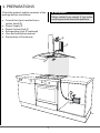
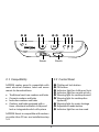
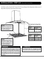
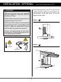
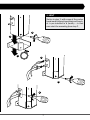
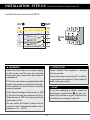
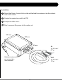
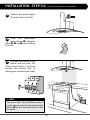
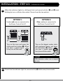
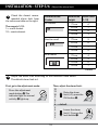
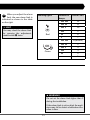
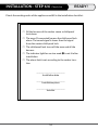
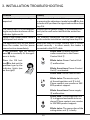
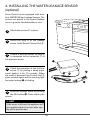
Installation manual
SAFERA Smart Stove Guard
with power control unit PCU3
v4.2.1 ENG Smart PCU3
1
CONTENTS
Warnings
1. Preparations
ѥѥ WARNING
2. Installation
Read user and installation manual before
using or installing the appliance.
3. Troubleshooting
Install and check the application according to the instructions. SAFERA is not liable for any damages or expenses caused
by inappropriate installation.
4. Optional: Installing the Water Leakage
Sensor
Check that the Stove Guard is compatible
with the cooker (see section 1.1).
Follow these instructions carefully and
pay particular attention to the instructions marked in the following way:
If the network cable is damaged, it must
be replaced by the service personnel of
the manufacturer or their representative
to avoid hazards.
ѥѥ WARNING
Follow instructions marked with a warning accurately to prevent injury to persons and damage to property.
All electrical connections must be carried
out by a qualified electrician.
⚐⚐ ATTENTION
⚐⚐ ATTENTION
Follow instructions marked with a note
carefully to prevent damage to property.
If the appliance was stored in a cold
space, it must be allowed to warm up to
room temperature before connecting it to
electric network.
ѧѧ HINT
Hints give you useful advices on using the
appliance.
2
1.Preparations
ѥѥ WARNING
Check the product and the contents of the
package before installation:
Please contact your vendor if you notice
anything unusual about the appliance.
• Central Unit (pre-installed into a
cooker hood) Ⓐ
• Power Supply Ⓓ
• Power Control Unit Ⓒ
• Extinguishing Unit Ⓔ (optional)
• User and installation manual
• Declaration of Conformity
Ⓓ
Ⓔ
Ⓐ
Ⓒ
3
❽ ❾
❸ ❶
❷ ❹
Sensor
❺ ❻ ❼
Nozzle
2.1 Compatibility
2.2 Control Panel
SAFERA cooker guard is compatible with
most electrical cookers, hobs and ovens
meant for household use:
❶ Child proof lock button
❷ OK button
❸ Indicator light for child proof lock
❹ Indicator light for normal activity
❺ Warning light for cooktop hazard
❻ Warning light for cooktop fire
(optional)
❼ Warning light for water leakage
❽ Adjustment mode button
❾ Indicator light for service need
•
•
•
•
Traditional cast-iron cookers and hobs
Ceramic cookers and hobs
Induction cookers and hobs
Cookers and hobs equipped with a
timer, afterheat indicator, child proof
lock or integrated switch-off system
SAFERA Smart is compatible with cookers
no wider than 90 cm, see installation step
1/6.
4
Installation - step 1/6
Mount the Central Unit
Install the cooker hood with Central Unit Ⓐ according to the dimensions below even if
they differ from the instructions of the hood:
With optional extinguisher
unit Ⓔ:
Width
Align the Central Unit
±15 mm with the centre of the cooktop.
Cooker
width
Installation
Height
Max. 60 cm ☐ 50 - 60 cm
☐ 60 - 70 cm
Without extinguishing unit:
Cooker
width
Installation
Height
Max. 60 cm 45 - 75 cm
Depth
Align the sensor of Central Unit (white lens)
±100 mm with the centre of the cooktop.
60 - 90 cm
60 - 75 cm
ѥѥ WARNING
⚐⚐ ATTENTION
The extinguishing area is approx. 60 cm in
diameter, when the installation height is
in accordance with the table. The installation height has an effect on the size of the
extinguishing area and the extinguishing
capacity.
The Central Unit Ⓐ is plugged into the
wall socket with its own power supply Ⓓ.
5
Installation - Optional
Install the Extinguisher unit Ⓔ
Install extinguishing unit Ⓔ on top of the
cooker hood according to the figures below (either A or B) and steps 1-6 on the
figures on the right.
ѥѥ WARNING
Make sure that the hose is not squeezed
after the installation. Minimum radius for
the hose is 50 mm.
Highest allowed operation temperatre for
extinguishing unit Ⓔ is 50°C.
Option
With some of the cooker hood models the
extinguishing unit Ⓔ is preinstalled in the
factory: in that case ensure that the hose
and the cable are properly connected.
A
E
Service and replacement of the extinguishing unit Ⓔ may only be done by service authorized by SAFERA.
Option
Max.
T<50°C
B
Min.
R>50mm
E
6
ѧѧ HINT
Notice in step 1: with some of the cooker
hood models the extinguishing unit bracket is pre-installed in a factory - in that
case start the mounting from step 2.
2
3
1
5
4
6
7
Installation - step 2/6
Mount the Power Control Unit Ⓒ.
Install the Power Control Unit PCU3.
IN
OUT
PE
PE
N
L/N
MAX
230V 16A
400V 10A
L
L2
MAX
230V 16A
400V 10A
L
L3
MAX
230V 16A
400V 10A
L
L1
OFF
MICRO DISCONNECTION
ѥѥ WARNING
⚐⚐ ATTENTION
Make sure that there is no power supply
to the cooker and the oven by removing
their fuses. Also ensure that the cooker is
switched off.
Power Control Unit requires a neutral
wire to operate.
Install the power control unit Ⓒ so that it
is not exposed to moisture. Check that all
cables can move freely.
OUT-wires are always energized when the
power control unit is connected to the electrical network. If a wire is loose, it must be
properly covered.
ѧѧ HINT
If you are replacing a cooker, press the
adjustment mode button ❼ for five seconds until you hear a signal. Continue the
installation according to step 3/6.
If the element voltage of the cooker is 400
V, the fuse can only be maximum of 10 A.
If the element is 230 V, the fuse can only be
maximum of 16 A.
Do not install the Power Control Unit to
excessive heat: Operational ambient temperature is +5 … +40°C.
8
Installation
1
Mount the Power Control Unit on the wall behind the cooker or into the cabinet
next to the cooker.
2
Couple the protective earth first (PE).
3
Couple the other wires.
4
Don’t reconnect the power to the cooker yet.
130 mm
180 mm
60 mm
IN
5 x 2,5 mm2
0,7 m
Optional water sensor connection.
See chapter 4.
OUT
5 x 2,5 mm2
1,3 m
9
Installation - step 3/6
1
Set up the wireless connection
Connect the power supply
Ⓓ to the Central Unit Ⓐ.
Press the adjustment
mode button ❽: indicator
lights ❺, ❻ and ❼ start blinking
by turns.
2
Put back the fuses for the
cooker and the oven. The
Power Control Unit Ⓒ will now
contact the Central Unit Ⓐ
which gives a sound signal (•••).
3
ON
ѧѧ HINT
You can re-start the installation process
anytime by pressing the adjustment mode
button ❽ for five seconds until you hear
the signal.
10
virranhallintayksikkö
Installation - step 4/6Kalibroi
Calibrate
the system
1
When the indicator lights for child proof lock and normal activity (❸ and ❹) start
blinking by turns, calibrate the cooker. Choose from the two options:
Option 1:
Option 2:
or
Cooker and oven are connected to
the Power Control Unit Ⓒ.
Only cooktop is connected to
the Power Control Unit Ⓒ.
or
Ⓒ
Ⓒ
Ⓒ
Turn on the oven and press the
child proof lock button ❶. When
you hear a sound signal
(•••), turn off the oven.
Turn on the biggest cooker plate
with maximum power and press
the OK-button ❷. When
you hear a sound signal
(•••), turn off the cooker.
ѧѧ HINT
With induction cooker, use a compatible dish.
2
Check that the indicator light for normal activity ❹ blinks every five seconds.
11
Installation - step 5/6
Check the closest recommended alarm limit from
the reference table on the right.
1
Adjust the alarm limit
Location of the
Cooker
In a corner
The range is 1-12:
1 = reacts fastest
12 = reacts slowest
Next to a wall
In an island
Installation
Height
Alarm Limit
(1-12)
75 cm
6*
65 cm
7
55 cm
8
45 cm
9
75 cm
5
65 cm
6*
55 cm
7
45 cm
8
75 cm
4
65 cm
5
55 cm
6*
45 cm
7
* Default
2
Adjust the alarm limit according to the reference table above.
The default alarm limit is 6.
First, go to the adjustment mode:
Then, adjust the alarm limit:
12
11
Raise the alarm
10
limit (+1): press the
9
OK-button ❷.
8
7
6 = default
5
4
Lower the alarm
3
limit (-1): press the
2
lock button ❶.
1
Press the adjustment
mode button ❽:The
indicator light for normal
activity ❹ lights up.
12
When you adjust the alarm
limit, the new alarm limit is
indicated as shown in the table
on the right.
3
Warning lights
Number of
beeps
Alarm Limit
••• •••
12
••• ••
11
ѧѧ HINT
••• •
10
You may check the alarm limit
by pressing the adjustment
mode button ❽ twice.
•••
9
••
8
•
7
Red
Green
••• •••
6 (default)
••• ••
5
••• •
4
••• 3
••
2
•
1
ѥѥ WARNING
Do not set the alarm limit higher than 9
during the installation.
If the alarm limit is set too high, the appliance may fail to detect a hazardous situation in time.
13
Installation - step 6/6
Check-list
READY!
Check the working order of the appliance and fill in the installation checklist: ፌፌ All the burners of the cooker cause a child proof
lock alarm.
ፌፌ The oven (if connected) causes the child proof lock
alarm. The sound signal is lower than the signal
from the cooker child proof lock.
ፌፌ The child proof lock turns off the oven and all the
burners.
ፌፌ The indicator light for service need ❾ is not lit after
installation.
ፌፌ The alarm limit is set according to the cooker location
_______________________________
Installation date
_______________________________
Installation place
_______________________________
Installer
14
3.Installation troubleshooting
Problem
Remedy
Installation is not proceeding as You can re-start the installation process anytime
expected.
by pressing the adjustment mode button ❽ for five
seconds until you hear the signal and continue from
step 3/6.
The central unit Ⓐ is not respond- Ensure that the power supply Ⓓ is connected coring to any button and none of the rectly to the wall socket and that the socket has
power.
indicator lights are lit.
None of the cooker plates cause a The wireless connection has not been properly
child proof lock alarm.
made: redo the installation starting from step 3/6.
The appliance turns off the power Make sure that the Power Control Unit Ⓒ is confrom the cooker, but the power nected correctly – in other words, the cooker is
comes back on immediately.
connected to the OUT cable.
If the indicator light for service
need ❾ is constantly lit, the appliance is faulty:
Blinks once: Problem with the
radio connection to the Power
Control Unit Ⓒ.
Press the OK button ❷ to find out the
problem type by the
indicator lights (see
on the right).
Blinks twice: Power Control Unit
Ⓒ malfunction.
Blinks three times: Power Control
Unit Ⓒ overheated.
Blinks once: Sensor malfunction.
Blinks twice: The service cycle
of the extinguisher unit Ⓔ is full.
Please contact your vendor or SAFERA product support.
Blinks three times: Power supply
Ⓓ malfunction.
Blinks once: The extinguisher unit
Ⓔ is triggered and needs to be replaced. Please contact your vendor
or SAFERA product support.
Blinks twice: The connection of the
extinguisher unit Ⓔ is faulty.
15
4.Installing the Water Leakage Sensor
(optional)
Stove Guard can be equipped with max.
four SAFERA Water Leakage Sensors. The
sensors are placed in the typical leakage
areas, e.g. under the dishwasher or sink.
1
Attach the sensors Ⓕ in place.
2
Attach the plug Ⓖ of the leakage
sensor to the Power Control Unit Ⓗ.
If there is an extra sensor, its plug Ⓖ
is connected to the connector Ⓘ of
the previous sensor.
3
C
Check the operation of the furthest
sensor Ⓕ by placing a damp paper
towel against it for 15 seconds. When
the water is detected, the Central Unit Ⓐ
gives a sound signal and the warning light
for water leakage ❼ is blinking.
4
G
I
H
F
Reset the leakage alarm by pressing
the OK button ❷. Clean and dry the
sensor.
5
ѧѧ HINT
If the sensor is left wet, the appliance will
give another alarm in an hour after signing off the previous one.
16