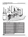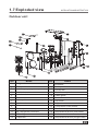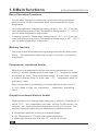
1
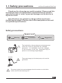
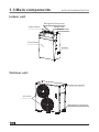
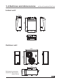
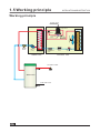
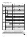
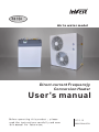
R410A
Air to water model
Direct-current Frequencjy
Conversion Heater
User’s manual
Before operating this product , please
read the instructions carefully and save
this manual for future use.
LVEI-18
380V/50Hz/3PH
Content
1. Before use
1.1 Safety precautions
1
1.2 Features and advantages
3
1.3 Main components
4
1.4 Outlines and dimensions
5
1.5 Working principle
6
1.6 Specifications
7
1.7 Exploded view
8
1.8 Main functions
10
2. Installation
2.1 System figure
14
2.2 Installation precautions
15
2.3 Applications
17
2.4 Air purging
26
2.5 Pre Start-up
27
3. Useage
3.1 Introduction of operation panel
28
3.2 Operation instruction
29
3.3 Setting the pump speed
32
4. Maintenance
4.1 Failure codes
33
4.2 Maintenance
35
4.3 Trouble shooting
37
5. Wiring diagram
5.1 Wiring diagram
39
1.1 Safety precautions
使 用 前
INSTALLATION AND INSTRUCTION
Thank you for choosing our quality product. Please read this
instruction sheet carefully before use and follow the sheet to
operate the unit in order to prevent damages on the device or
injuries to staff.
Specifications are subject to change without notice for
further improvement. Please refer to the name plate on the unit
for updated specifications.
Safety precautions
Symbols used
!
Warning
Prohibition
Suggestion
The installation, dismantlement and maintenance
of the unit must be performed by qualified
personnel. It is forbidden to do any changes
to the structure of the unit. Otherwise injury of
person or unit damage might happen.
Grounded
The power supply to the heat pump unit must be
grounded.
The water inside the heat exchanger should contains no chloridion
inside, and PH value among 6~8.
01
1.1 Safety precautions
INSTALLATION AND INSTRUCTION
Make sure the power supply to the heat pump
unit is off before any operations are done on the
unit.
Do not insert any foreign objects into the air
outlet grill when the fan motor is running.
Otherwise injury of person or unit damage
might happen.
Make sure no water or other liquid drips into the
electric box of the unit . Otherwise the unit might
be damaged.
Do not clog the evaporator by paper or any other
foreign objects, to keep the unit well
ventilated.
ON
OFF
It is mandatory to use a suitable circuit-breaker
for the heat pump and make sure the power
supply to the heater corresponds to the
specifications. Otherwise the unit might be
damaged.
Make sure to use a dedicated power line for the
heat pump only. Do not add other appliances to
the line.
02
1.2 Advantages
INSTALLATION AND INSTRUCTION
Advantages
This unit is using the latest DC inverter technology. It can adjust its working
frequency, so to give out its output according to the loading. It can work down to 25℃ with good COP.
The unit is designed with easy installation that no refrigerant charging or
copper pipe brazing is required on site. It can be widely used in house and villa.
This unit is with environment- friendly refrigerant R410A, which also provides
one of the highest energy efficiency ratings in the industry. Output of the
compressor and therefore the energy input requirements are constantly monitored
and adjusted at the most optimum level for the given indoor and outdoor
environmental conditions and the user' s desired demands from the system.
Microprocessor control system contains several enhanced software features to
make the operation of the system most advantageous and pleasing, under varying
environmental conditions.
Special vibration absorbers on the compressor allow operation of the system
with ultra low noise.
Auto-restart function keeps all settings in memory and automatically resumes
the operation after a power failure.
Compressor crankcase heater and bottom plate heater are available as
options for extreme cold conditions, enabling the unit to work in very low
ambient temperatures with much lessened defrost frequencies. Both these
optional heaters are electronically controlled based on the outdoor ambient
temperatures and a sophisticated logic.
Programmable timer function provides unattended operation of the system.
Acrylic coated enhanced aluminum fins on the coil heat exchanger extends
the fin life against corrosion and allows easier rainwater wash- down as well
as faster defrosts.
Copper tubing in all heat exchangers are made by using the latest
developments in the technology of inner grooved tubing by extending the
area of heat exchange in a more compact coil, therefore increasing the
operational efficiency.
03
1.3 Main components
INSTALLATION AND INSTRUCTION
Indoor unit
Refrigerant Connector
Cable Gland
Water Inlet
Water Outlet
Front Panel
Handle
Outdoor unit
Maintenance panel
Air outlet
Refrigerant Connector
04
1.4 Outlines and dimensions
INSTALLATION AND INSTRUCTION
Indoor unit
900
330
600
Outdoor unit
11 6 3
1053
792
47 9
Refrigerant connector
dimension:Φ9.52(3/8’)
Φ19.07(3/4’)
51 5
396
05
1.5 Working principle
INSTALLATION AND INSTRUCTION
Working principle
Power input
Compressor
Four-way
valve
Water
pump
Heat
exchanger
Refrigerant
gear
Indoor unit
Filter
Outdoor unit
Hot water outlet
Water tank
Cold water inlet
06
Expansion
valve
Heat exchanger
Water
Filter
Fan motor
Pin
valve
Three-way
valve
1.6 Specifications
INSTALLATION AND INSTRUCTION
Type
LVEI-18
380V/50Hz/3PH
Refrigerant
Capacity
R410A/3.185
COP
W/W
3.2-4.3
E. E . R
Btu/h.W
7.96-12.3
Cooling(heating)capacity
Cooling
Power
Heating
Dimension
Outdoor
A
2.3-8.5
Input power
W
1850-5700
Input current
A
mm
2.8-8.66
600(L)x300(D)x900(H)
1500-5600
Packing dimension
mm
700(L)x380(D)x990(H)
Net dimension
mm
1000(L)x460(D)x1200(H)
mm
1159(L)x555(D)x1234(H)
Packing dimension
inch
G1
inch
3/4”
inch
Working range in cooling
℃
Working range in heating
Water outlet temp.
℃
3/8”
0℃~ 55℃
-25℃~ 33℃
7℃~ 52℃
Indoor
℃
Kg
Outdoor
Kg
126
Indoor unit
dB
35
Outdoor unit
dB
rpm
Noise
Fan speed
Others
24907-61416
W
Gas connector
Liquid connector
Weight
7.3-18
3.5-13
11942-44356
Input power
Water connector
Temp.
KW
Btu/h
Input current
Net dimension
Indoor
Heating
Cooling
Function
Power supply
Outdoor unit
50
56
7500
Flow rate(Max./Nor./Min.)
Room temp sensor
L/s
KΩ
0.4/0.23/0.13
5K(25℃)
Indoor coil temp sensor
KΩ
5K(25℃)
Outdoor temp sensor
KΩ
5K(25℃)
Outdoor coil temp sensor
KΩ
5K(25℃)
KΩ
50 K(25℃)
Outdoor discharge temp sensor
Rated condition of test:
Cooling: water inlet/outlet: 12℃/ 7℃, ambient temperature: DB/WB 35℃/24℃;
Heating: water inlet/outlet 40℃/ 45℃, ambient temperature: DB/WB7℃/6℃;
The specifications air subject to change without prior notice.For actual
specifications of the unit, please refer to the specification stickers on the unit.
07
1.7 Exploded view
INSTALLATION AND INSTRUCTION
Indoor unit
22
21
25
23
18
20
19
24
17
16
15
14
2
1
NO
1
2
3
4
5
6
7
8
9
10
11
12
13
08
3
4
Name
Front panel
Electric box cover
Bracket for Electronics
Wire Clip
Terminal block
Main processor PCB
Relay
Mechanical temp. controller
Plate heat exchanger fixture
Plate heat exchanger support
Plate heat exchanger
Water pump
Electric heater
6
5
NO
14
15
16
17
18
19
20
21
22
23
24
25
7
8
9
10
11
12
Name
Expansion tank
Gasing
Rubber feet
Small Handle
Cable gland
G1" water pipe connector
3/8" refrigerant connector
7/8" refrigerant connector
Soft pipe
Temperature sensor
Top cover
Wired controller
13
1.7 Exploded view
INSTALLATION AND INSTRUCTION
Outdoor unit
20
22
23
19
24
25
26
18
21
17
4
3
1
NO
1
2
3
4
5
6
7
8
9
10
11
12
13
6
7
13
9 10 11 12
14
15
16
2
Name
Fan guard
Front panel
Pressure gauge (High/Low pressure)
Fan blade
Motor bracket
Fan motor
Bottom plate
Liquid receiver
Compressor
Four-way valve
3/8" refrigerant connector
7/8" refrigerant connector
Evaporator
5
8
NO
14
15
16
17
18
19
20
21
22
23
24
25
26
Name
Bulkhead
Back panel
Valve plate
Maintenance panel
Cable gland
Controller
Top panel
Support
Compressor crank heater
Electronic expansion valve
Temperature sensor (dual head)
Wired controller
Temperature sensor (single head)
09
1.8 Main functions
INSTALLATION AND INSTRUCTION
Basic Operation Functions
The two basic operation functions are cooling and heating operations,
either of which can be controlled by either room temperature or water
temperature.
In cooling operation, Temperature setting range is 16℃ - 31℃ if you use
room temperature as the index, Temperature setting range is 7℃ - 25℃ if
you use water temperature as the index .
In heating operation, Temperature setting range is 16℃ - 31℃ if you use
room temperature as the index, Temperature setting range is 26℃ - 52℃ if
you use water temperature as the index .
Memory function
The unit will recover its latest working settings automatically after power
failure . The compressor restart interval time is 3 minute, to protect the
compressor.
Compressor crankcase heater
When the unit is powered on the first time and the compressor is not
working, if outdoor ambient temp is lower than -5℃, compressor starts
to preheat by itself . After compressor works,
if outdoor ambient temp is lower than
3 hours after it stops ,
-3℃, compressor starts to
preheat by itself .
When compressor is in preheating, if outdoor ambient temp is over 0℃,
or unit needs to start the compressor
,
compressor preheating
stops .
Output for external electric heater
When system runs in heating mode (heat pump), ambient temperature is
below 10℃, and compressor has been running for 25 minutes, the
controller will check the system temperature in every 15 minutes. The
auxiliary electrical heater turns on when below conditions are met :
A. Compressor has been running at its highest speed ;
B. Set temperature is 3℃higher than water temperature.
C. Water temperature rises less than 1℃ in over 15 minutes.
10
1.8 Main functions
INSTALLATION AND INSTRUCTION
When water temperature reaches the preset value , and keeps
1 minute or compressor stops running, this auxiliary electrical
heater turns off, when system begins to do the checking as above .
stable for
Limit on Water outlet temperature (when air temperature
works as the set temperature)
When WOT (water outlet temperature) ≥34 ℃, the controller will set a
limit on compressor' s running speed, with its current running speed as
maximum.
When WOT ≥36 ℃, compressor' s running speed will be lowered down
towards its lowest speed, until water outlet temperature drops below 34 ℃.
Then the controller stops lowering compressor' s running speed and begin
to raise it back, but its maximum speed will be one level lower than its
previous speed before this lowering process.
When WOT≤32 ℃ and compressor keeps on running 6 0 minutes
without any frequency drop or system shutdown for protection, then the
limit on compressor' s running speed will be released.
When WOT≥38℃ or compressor' s running speed is lowered to its lowest
speed but water outlet temperature is still higher than 34℃ after 2
minutes, then compressor stops. After water outlet temperature drops
below 32 ℃, compressor restarts.
Defrosting function in heating mode
When the unit works in heating, it will start defrosting automatically
according to the coil temperature and defrosting interval time.
a) Defrosting operation starts when below conditions are met, when
defrosting light flickers.
1) Condensing coil temperature below -3℃ and lasts for 3 minutes.
2) Compressor has been running for not less than 5 minutes
3) Total running time of compressor is longer than interval between two
defrosting operations
b) When one of below condition is met, the system quits from defrosting
operation
1) Defrosting operation lasts more then 8 minutes;
11
1.8 Main functions
INSTALLATION AND INSTRUCTION
2) Defrosting operation lasts for more than 10 seconds, and condensing
coil temperature is higher than 17℃.
Evaporator overheating protection
When evaporator temperature≥52℃, system enter into evaporator
overheating protection, and compressor lowers down its running
speed towards F1, until this temperature drops lower than 49℃. Then
compressor takes the speed 1 level lower than its previous speed
before overheating protection as its maximum running speed.
When this Temp drops down to 47℃ and lasts for 5 minutes, the limit
on compressor running speed will be released.
If evaporator temperature rises above 55℃ and lasts for 5 seconds,
then compressor stops. And it will resume its normal operation until
this temperature drops down below 47℃.
Protection against Compressor's improper operation
During compressor' s start-up or running, if the controller detects no
feedback from compressor, or abnormal loads inside compressor, or
improper start-up, compressor will stops for 3 minutes and then re-start.
(Compressor can re-start at most three times when fed with power; if this
problem still exists, the controller will judge it as compressor drivingfailure, and relevant protection will be triggered. Then compressor can
only be turned on after problem solved and system re- fed with power.
Protection against Improper Current
When system running current is bigger than a certain value, controller will
impose relevant limits on compressor' s running frequency, then its
running speed will stop rising.
When this current 0.5A smaller than this certain value,system' s running
speed drops by 1Hz/second towards 30Hz, until running current is
smaller than 16A.
When this current is 1A bigger than this certain value,controller will stop
the compressor no matter at what speed it runs.
12
1.8 Main functions
INSTALLATION AND INSTRUCTION
Compressor gas discharge temperature protection
When compressor gas discharge temperature exceeds 92℃, the
controller will keep its running frequency from rising. When this
temperature exceeds 97℃, the controller will record the compressor' s
running speed, and lower it down towards 30Hz. If compressor gas
discharge temperature drops below 87℃, then this process stops and
controller adjusts compressor' s running speed according to difference
between room temperature and preset temperature; However, its
maximum running frequency will be 1 level lower than recorded value.
When compressor gas discharge temp. is below 92℃ and lasts for 1 0
minutes, its maximum running frequency will increase by 1 level. If
this discharge temperature exceeds 103℃, the compressor stops, and
outdoor fan motor turns off in 1 5 seconds. And the system turns on
until gas discharge temperature drops below 90 ℃ and compressor has
been off for 3 minutes.
Delayed Start-up of Compressor
After compressor stops, it can only restart in 3 minutes (this protection is
functional in cooling mode or when system changes its operation mode
between dehumidification and heating) . However, when the unit is
powered the first time, compressor starts up in 1 minute instead, to
ensure proper communication between indoor and outdoor unit.
13
2.1 System figure
INSTALLATION AND INSTRUCTION
F2
F1
Water
tank
Indoor
unit
Hot water pipe
Filter
City water pipe
Valve
City water
Outdoor unit
14
2.2 Applications
INSTALLATION AND INSTRUCTION
Applications
Application 1: This installation is for supplying sanitary hot water only.
Sanitary hot water
City water inlet
Drainage
Sanitary hot water
Application 2: This installation is for supplying floor heating hot
water only.
Pump 1
Floor Heating
City water inlet
Drainage
Floor Heating
15
2.2 Applications
INSTALLATION AND INSTRUCTION
Application 3: It provides both floor heating hot water and pre-heated
sanitary water.
Pre-heated
City Water
Pump 1
Floor Heating
City water inlet
Drainage
Floor Heating and Pre-heated Sanitary Water
Application 4: It provides hot water for central house heating and hot
water system.
Sanitary Water (Hi. Temp.)
Solar collector
Pump 3
Room Temp.1
Pump 1
Elec. heater
Radiator
E1
Pump 2
Floor Heating
Room Temp.2
City water inlet
Drainage
Heat Pump and Solar System for Heating & Sanitary Water
16
2.3 Installation
INSTALLATION AND INSTRUCTION
Location of indoor unit
1.Indoor unit can be placed at any free space in the house, like the room, garage, or
basement.
2.Indoor unit can be hang on the wall, or placed on a flat and solid ground.
3.Free space should be left on the device, for future maintenance.
4.Install the indoor unit close to the outdoor unit as much as possible, so to reduce
the energy loss.
5.The unit should be free from corrosive and moisture surrounding.Otherwise the
lifetime of the unit might be shortened.
6.Unit should be away from explosive and flammable gas and liquid.
7.Indoor unit should be away from direct sunshine. Otherwise the lefetime of LCD
display maybe shortened.
8.Ensure that the electrical supply corresponds to the specification indicted on the
unit's name plate. The unit must be earthed to avoid any risks caused by insulation
defects.
Moving of the unit
Moving the unit by lifting two handles.
Handle
Connection of power cable
Warning:
1.It is recommended to use a suitable breaker for the heat pump and make sure the
power supply to the heater corresponds to the specifications. Otherwise the unit
might be damaged.
2.The power supply to the heat pump unit must be grounded.
3.Cable should be fixed tightly, to ensure it won't get lossen.
17
2.3 Installation
INSTALLATION AND INSTRUCTION
Installation of cable between indoor&outdoor unit
at indoor side
1. Take off the front panel.
2. Make a four core cable ready
(4*1.5mm2), and insert this
cable into indoor unit through the
cable gland on top of the unit.
3. Connect the cable to the
terminal block.Blue cable must be
connected to terminal "N", while
other cables can be connected to
port "R" "S"and "T" arbitrarily.
4. Fix the cable with cable fixture,
and install the front panel back.
After connect the power cable to
the terminal block correctly,
please install the power cable
clip back to lockup the power
cable.
18
2.3 Installation
INSTALLATION AND INSTRUCTION
Location of outdoor unit
1.The installation, dismantlement and maintenance of the heat pump must be
performed by qualified personnel.
2.Indoor unit can be placed at any free space in the house, like the room, garage,
or basement.
3.The unit must be installed outdoors in an area with sufficient clearance to
provide free air circulation through the coil. Please refer to the following figure to
choose the right place for the unit. .
Minimum space left
>50cm
>50cm(Minimum distance
from the front)
>65c m
>40cm
>50cm( Minimum distance
from the back)
4.The unit should be free from corrosive and mosture surrounding.Otherwise the
lifetime of the unit might be shortened.
5.Install the indoor unit close to the outdoor unit as much as possible, so to reduce
the energy loss.
6.Unit should be away from explosive and flammable gas and liquid.
7.Ensure that the electrical supply corresponds to the specification indicted on the
unit's name plate. The unit must be earthed to avoid any risks caused by insulation
defects.
8. when installing the unit, introduce a tilt of 1cm/ m for rain water evacuation.
9. when installing the unit in harsh climatic
conditions, sub-zero temperatures, snow,
humidity.., it is recommended to raise the
unit off the ground by about 20cm.
10.Rubber vibration absorbing mountings
are recommended.
11.When sitting the unit, take care to leave
sufficient free space all around it for
carrying out maintenance.
Rubber
vibration
sit on bracket
19
2.3 Installation
INSTALLATION AND INSTRUCTION
Cable connection of outdoor unit
Installation of cable between indoor&outdoor unit at outdoor side
Cable gland
1. Take off the maintenance
panel on the right side of the unit.
2. Insert the cable between indoor &
outdoor unit into the outdoor unit
through the cable gland. Connect this
cable to the 4-position terminal block.
Note: Please ensure the connection of this cable in the
indoor unit corresponding to the connection in the
outdoor unit.
3. Fix the cable with cable fixture.
4. Make a 5 core power cable ready
(5*1.5mm 2) , and insert this cable
into outdoor unit by through the
cable gland on the outdoor unit.
20
2.3 Installation
5. Connect this power cable to the 5way terminal block in the outdoor
unit. Please note blue wire must be
connected to port 'N", and
yellow/green cable must be
connected to port “
”.
INSTALLATION AND INSTRUCTION
6. Fxi the power cable with cable fixture,
and install back the maintenance panel.
21
2.3 Installation
INSTALLATION AND INSTRUCTION
Connection of refrigerant pipe
Refrigerant pipe transfers not only the refrigerant, but also the energy, between
indoor and outdoor unit. If the refrigerant system is not fully vacummed, or gas
amount is not correct, the unit performance may be influenced.
Note the followings when choosing a refrigerant pipe:
1. Ensure good quality copper pipe is used. This copper pipe must be thick
enough to bear the pressure of R410A refrigerant.
2. Refrigerant pipe must be well insulated.
3. Connector of refrigerant pipe must be checked to ensure no leakage happens.
4. When pipe bending is needed, bend the pipe in a gentle way.
5. Dry the pipe before installation, to ensure no water remains
Indoor
Outdoor
6. It is recommended to have the refrigerant pipt go
through the wall by using a wall sleeve.
Insulation
7. Two refrigerant pipes should be
packed with insulation sperately,
otherwise GREAT heat loss may
happen.
Refrigerant
pipe
Installation of refrigerant pipe:
1.The size of the refrigerant pipe is 3/8"( Φ 9.52) and 3/4"( Φ 19.07).
Both should be well insulated before installation.
22
2.3 Installation
INSTALLATION AND INSTRUCTION
1. Connect one side of refrigerant
pipe to the indoor unit.
2. Connect the other side of
refrigerant pipe to the connectors
on the outdoor unit, as shown
in the picture.
3.Make a vacuum pump and
pressur gauge set ready. Connect
one soft pipe of the pressure
gauge to the vacuum pump.
4.Connect the other soft pipe of
pressure gauge set to the unit, as
shown in the picture.Open the
pressure gauge and start the
vacuum pump.
5. Vacuum the unit by at least 10
minutes. Close the pressure gauge and
stop the vacuum pump, till minus
pressure shown on the pressure gauge
(<0Mpa).
23
2.3 Installation
INSTALLATION AND INSTRUCTION
Anticlockwise
6. Take off the copper nuts on both
connectos, and open both
connectors by using a hex wrench.
Be ensure that both connectors
are fully opened.
Size of Hex Wrench:5mm
Note:Connectors can only be opened after vacuum finished!
7. Install the copper nuts back.
Leakage detecting
Put some suds on all connectors of indoor and outdoor unit, for
leakage detecting after installation.
24
2.3 Installation
INSTALLATION AND INSTRUCTION
Water pipe connection
The designing, installation, commissioning and maintenance of water system
should be performed by professional installer having good knowledge
of standards and local regulations, as well as experience of this type of
equipment.
Filter installation
A mesh filter must be installed in front of the water inlet of the unit and water
tank, for keeping the water quality and collecting impurity contained in the
water . Take care to keep the water filter mesh towards the bottom.
Check valve is recommended to be installed at both sides of the filter, so as
to clean or change the filter in a easier way.
water inlet
Connect to
water tank
water inlet
Filter
One-way valve
Drainage hose
Shut-off valve
Filter
Indoor unit
Note:All the hot water pipe and water
connections should be insulated , to reduce
the energy loss .
Please ensure the flow rate of the water system should
be no lower than the minimum allowable flow rate required
by the unit. Add one pump to the water system, if flow rate
is too small().
25
2.4 Air purging figure
INSTALLATION AND INSTRUCTION
Air purging figure
Water outlet
Indoor
unit
F4
Water inlet
water
F3
tank
F2
Filter
F1
(open)
(open)
Ball valve
(open)
City water
Outdoor unit
Air purging
The whole water system of this unit should be a closed water system. Because of
this, please purge the air inside as following after all the water pipe
connection work finished:
1.Open the water tap at the lowest level, so the air inside the sanitary water
system can be purged out by the pressure of water.
2.Open the filling valve to fill the whole water tank and the water system with
water (this process may take around 20 minutes).
3.Close all the valves when there is water coming out from the end of the
water system.
4.Air purging finished!
Note: If the water supply is cut off, the unit will show protection code on its
screen. The customer should cut the power off till the water coming again. It
is necessary to purge the air again when restart the unit after the water was
cut off.
26
2.5 Pre Start-up
INSTALLATION AND INSTRUCTION
Pre Start-up
Before starting up the unit, a certain number of verifications must be performed
on the installation to ensure that the unit will operate under the best possible
conditions. The check list below is not exhaustive and should only be used as a
minimum reference basis:
1.Make sure fan rotates freely.
2.Inspect all water piping for flow direction.
3.Verify all system piping is correct for operation as per installation
requirements.
4.Check voltage of the unit power supply and make certain voltage is within
authorized limitations.
5.Make sure the unit is properly grounded.
6.Check the presence of protective and breaking devices.
7.Check all electric connections for tightness.
8.Check all piping for leaks and air is well ventilated.
Unit Start-up
After ensuring all electric connections conform to the local regulations, follow
the Operation Instructions to start-up the unit.
After start-up the unit, if there is a abnormal sound, please shut off the power
supply immediately to ensure the safety of the unit.
27
3.1 Introduction of operation panel
Introduction of operation panel
ON/OFF
Timer
MODE
Confirm/
K e y Lock
Down-regulation
Up-regulation
Display
28
Meaning
Function
Heating
When the unit works in heating mode ,
Cooling
When the unit works in cooling mode ,
Hot water
When the unit works in hot water mode ,
Defrosting
When the unit works in defrosting ,
Key lock
When buttons are locked ,
Parameter
setting
When parameter setting is activated ,
value or code
To display temperature, timer, parameter,
error code and so on.
Time
The unit will clear its clock time when power
failure happens.
Water
temperature
When water temperature mode is activated,
is ON.
is ON.
is ON.
is ON.
is ON.
is ON.
is ON.
3.2 Operation instruction
Set temperature
Timer function
INSTALLATION AND INSTRUCTION
When changing the set temperature,
is ON.
When timer function is activated,
is ON.
Standby
The unit is standby when it is fed with power.
※The unit will clear its clock time when power failure
happens. The customer needs to set the time again.
ON/OFF
When the unit is standby, press
to turn on the unit. The
unit will work in its last working mode. Press
again to
turn off the unit.
※ The unit will recover its latest working settings
automatically after power failure.
Mode selection
Keep on pressing
button to choose water
temperature or air temperature as the set temperature.
When water temperature works as the set temperature,
is ON; When air temperature works as
the set temperature,
is OFF.
Mode selection
Press
to choose the unit operation mode. It comes in
the sequence:
( Heating) →
(Cooling ) →
( Hot
water).
29
3.2 Operation instruction
INSTALLATION AND INSTRUCTION
Temperature setting
When the unit is ON, press
once, the set temperature
increases by 1℃; press
once, the set temperature
decreases by 1℃. Keep on pressing
or
, the
temperature can be increased or decreased by 5 ℃.
When changing the set temperature,
is ON.
Parameter setting
When power is fed and unit is off , press
or
to choose
target Parameter.
Press
to activate parameter setting process when
parameter flickers. User can set its value with button
or
; Press
again to confirm the setting work,
otherwise the setting Value will not be saved. and the
system will exit this parameter Setting program automatically
in 10 seconds, or by pressing
.
Parameter 1
Parameter 2
Parameter 1
indicates the local
time. The time is
always presented in
the 24-hour system
This parameter
has no function
in this unit.
Parameter 3
Parameter 3 indicates the duration time for back light. It can
be set to 00, 10, 20, and 30. While 00 means the back light
is always ON, and 10, 20, and 30 means the duration time
for back light is 10 seconds, 20 seconds and 30 seconds.
30
3.2 Operation instruction
INSTALLATION AND INSTRUCTION
Timer function
To set the ON timer, press
button.
turns on and
blinks. Press
to set the timer in hours, and
to set
the time in minutes. After it is done, press
to confirm
the ON timer setting and enter the OFF timer setting,
with
blinks. Set the OFF timer by pressing
and
. After this done, press
to confirm the
OFF timer setting, with
shown on the operation
panel, indicating that the timer setting is finished.
If the ON timer or OFF timer setting is not confirmed by
pressing
, the setting value is not saved.
The timer setting can be cancelled by keeping on
pressing
, with fading from the operation panel.
▲Timer ON
Timer ON setting doesn't function
when the unit is working. It will be
activated when the unit is turned
OFF.
▲Timer OFF
Timer OFF settings only functions
after the unit starts. It can be
activated when the unit is
turned ON.
Key lock
When the unit is ON, press
for 5 seconds, to lock
all the buttons, with
shows. Press
for 5
seconds again, to unlock all the buttons.
31
3.3 Setting the pump speed
INSTALLATION AND INSTRUCTION
Setting the pump speed
The pump speed can be selected on the pump.
The default setting is highest speed(Ⅲ).If the water flow in
the system is too high(e.g:noise of runing water in the
installation) the speed can be lowered (Ⅰ/Ⅱ).
The available external static pressure (ESP, expressed in
mH 2O) in function of the water flow (l/min) is shown in the
graph below.
water pump performance curve
32
4.1 Failure codes
INSTALLATION AND INSTRUCTION
Failure codes
Error
Codes
E0
E1
E2
F2
Causes
Ways to check and remedies
1.Wire connection between wired
controller and PCB open or
short-circuited
2.Wired controller failure.
1.Wire connection between wired
controller and PCB open or
short-circuited
2.Wired controller failure.
2.Change it.
1. temp. sensor open or
short-circuited
1. Measure with a multimeter at 20K to check whether
it is shirt-circuited or open. If yes, change it..
2.temp. sensor resistance
drifting
2.Measure with a multimeter at 5 0K to check the
sensor resistance. Take ambient temp. into
consideration. If it isdrifting, change it.
3.Temperature sensors not well
connected to the wired controller.
3.Check whether the sensor connection
gets loose. Fasten it.
1. water inlet Temp sensor failure
1.Check whether the sensor connection gets loose.
Fasten it.
2.Wire connection between wired controller and
indoor PCB open or short-circuited.
3.water inlet Temp sensor resistance drifting.
2.water outlet Temp sensor
failure
1.Check whether the wire connection
gets loose. Fasten it.
2.Change it.
1.Check whether the wire connection
gets loose. Fasten it.
1.Check whether the sensor connection gets loose.
Fasten it.
2.Wire connection between wired controller and
PCB open or short-circuited.
3.water outlet Temp sensor resistance drifting.
3. Coil Temp sensor failure
1、Check whether the sensor connection gets loose.
Fasten it.
2、Wire connection between wired controller and
indoor PCB open or short-circuited.
3、Temp sensor resistance drifting. temp. sensor
resistance drifting.
F1
Communication failure
1、Check whether port gets loose. Fasten it.
2、Change the PCB.
3、Change the outdoor PCB
F4
1.Check whether PFC transducer gets loose. Fasten
Compressor drive failure、IPM
it.
failure、IPM protection (overload)、
2.Change PFC transducer.
drive protection
F3
Current or Voltage detector failure
1.Change PCB
EEPROM failure
1、Check whether EEPROM gets loose.
Fasten it.
2.Change EEPROM
F5
33
4.1 Failure codes
INSTALLATION AND INSTRUCTION
Too highr coil Temp in heating
1. Check the water flow of the unit
2. Too high ambient and water Temp. Reduce the set
water Temp.
Too high pipe Temp in cooling
1.Check the water flow of the unit
2.Too low ambient and water Temp.Increase the set water
Temp.
Over-current protection
1.Check the water flow of the unit.
2.Too high (low) ambient, and too high(low) set water
Temp. Decrease or increase the set water Temp.
F7
Too high or too low voltage
1.Check the voltage of the power supply.
2.Change the outdoor PCB
F8
Pressure switch failure
1.Check the pressure of the system
2.Change the pressure switch
F9
EEPROM failure
1.Check whether EEPROM gets loose.
Fasten it.
2.Change outdoor EEPROM
F6
Ambient temp. sensor failure
Fb
Pipe temp. sensor failure
Compressor discharge temp.
sensor failure
1、Check whether the sensor connection gets loose.
Fasten it.
2、Wire connection between wired controller and PCB
open or short-circuited.
3、Temp sensor resistance drifting.
Fc
System protection caused by too
high(low) pressure
1.Measure the high (low) pressure switch with a
multimeter to check whether it is shirt-circuited or open.
If yes, change it.
2.Check the water flow of the unit.
Fd
System protection caused by the
ambient Temp.
1.Check the ambient Temp sensor.
2.Check whether the ambient Temp is too high(low) for
working (Ambient lower than -1℃or higher than 65℃ in
cooling, lower than -25℃ or higher than 33℃ in heating).
Maintenance
1.It is forbidden to change the inner structure and wiring of the unit. Otherwise
injury of person or unit damage might happen.
2.If the unit fails to work properly, please cut the power supply immediately.
The maintenance work must be performed by qualified people.
3.“Failure check list” in this manual is helpful to find out and fix the
failure of the unit.
4.After long time running, the evaporator coil may get dirty, which will
affect the performance of the unit. It is suggested to clean the surface
of the coil occasionally.
34
4.2 Maintenance
INSTALLATION AND INSTRUCTION
Maintenance of the electric components
For maintenance of electric components in indoor unit:
Electric box cover
Main processor PCB
Figure 1
Figure 2
Figure 3
1. Cut off the power supply.
2. Take off the front panel.
3. For maintenance of main processor PCB, please open the electric box cover.
For maintenance of electric components in outdoor unit:
1. Cut off the power supply.
2. Take off the maintenance panel.
3. Take off the electric cover .
4. Do the checking of electric components.
35
4.2 Maintenance
INSTALLATION AND INSTRUCTION
Condenser Coil
The condenser coils donot require any special maintenance, except when
they are clogged by paper or any other foreign bodies. Cleaning is by washing
with detergent and water at low pressure, and then rinsing with clean water:
1. Before cleaning, make sure the unit is off.
2. Inner of the unit must be cleaned by qualified person.
3. Donot use gasoline, benzene, detergent etc. to clean the unit. And donot
spray with insecticide. The unit may be damaged. The cleanser special made for air
conditioner cleaning is recommened.
4. Spray air conditioner cleanser into the coils. Let the cleanser sit for 5 ~ 8
minutes.
5. Then, spray the coil with clean water.
6. An old hairbrush works well for brushing surface dirt and lint off the fins.
Brush in the same direction as the slots between the fins so the bristles go between
the fins.
7. After cleaning, use a soft and dry cloth to clean the unit.
Gas Charging
even under severe operating conditions. If your unit needs recharging, then it has a
leak, and adding refrigerant will not solve the problem. The leak must be located and
repaired.
1.Gas charging must be performed by qualified
person.
2.One can find out whether the system has enough
refrigerant inside by checking the low pressure inside
the system.
Cleaning of the filter
The Y-filter must be cleaned occasionally to ensure the water flow of the
water system.
36
4.3 Trouble shooting
INSTALLATION AND INSTRUCTION
Trouble shooting
Malfunction
Possible Causes
1.Power supply cut-off
2.Power fuse burnt out
Heat pump
unit is out
of operation
Fan is out
of operation
Low heating
capacity
3.Unit protection
3.If the protection is caused by the failure,
please refers to the failure code list and
fix the failure before restarting the unit.
4.Loose connection of
power cables
4.Check the connections.
5.Compressor failure
5.Replace the compressor.
1.Fan motor wire loose
1.Check the wire connections.
2.Fan motor burnt
2.Change the fan motor.
3.Fan motor relay fails
3.Change the fan motor relay.
1.Coil fins are dirty
1.Clean the evaporator coil
2.Air inlet/outlet blocked
3.Lacking of refrigerant.
Too high noise
from the water
pump, or no
water flow
when the
water pump
is running.
Remedies
1.Check the power supply.
2.Check whether the unit is well grounded.
If yes, check the fuse and change it if
necessary.
1.Lacking of enough water.
2.Air inside the water system.
3.Water valve closed.
2.Remove any object that blocks the air
circulation of the unit.
3.Inspect the unit for leakage and fix it if any.
Discharge all refrigerant and charge the unit
again with right amount.
1.Check the water filling device. Fill the
system with enough water.
2.Purging the air out.
3.Check all the valves to ensure they are
fully opened.
4.Filter is blocked
4.Clean the filter
1.Too much refrigerant.
1.Discharge all refrigerant and charge the
unit again with right amount.
2.Discharge all refrigerant and charge the
2.Air inside the refrigerant system.
Too high
unit again with right amount.
compressor
3.Check
the water flow of the system. Use
discharge
3.Too small water flow
a bigger pump if necessary.
pressure
4 . Too high water temperature
Too low
suction
pressure
4.Check the value of the water temperature
sensor, to ensure it works properly.
1.Drier filter blocked
1.Change the drier filter
2.Expansion valve failure
2.Check and replace the expansion valve.
3.Inspect the unit for leakage and fix it if any.
Discharge all refrigerant and charge the unit
again with right amount.
3.Lacking of enough refrigerant
37
4.3 Trouble shooting
1.Coil temperature sensor failure
Unit can
not defrost
2.Air inlet/outlet blocked
properly
INSTALLATION AND INSTRUCTION
1.Check the position and value of the coil
temperature sensor. Replace it if necessary.
2.Remove any object that blocks the air
circulation of the unit. Clean the evaporator
coil occasionally.
The following phenomenon may not be problems. Please contact with a
professional maintenance staff.
NO
1
Malfunction
The unit is
not running
Possible Causes
1.May be caused by compressor restart protection. The interval time
of compressor restart is 3 minutes.
2.Please check whether the circuit breaker, the power supply is open.
When the unit is running, if sound of the running water can be heard
from the system of the unit, it is the sound of running of the
refrigerant. This is not a failure.
2
The unit is
too noisy
3
The unit output temperature setting is too high in cooling mode, or too low in heating
mode. Check whether the room is too big. Check whether there are
is too small
Check whether the air inlet/outlet is blocked. Check whether the
too many people inside the house when unit is in cooling operation.
38
5.1 Wiring diagram
INSTALLATION AND INSTRUCTION
R120800
Indoor unit
S L N
ACL-CN204
S-CN212
HEAT
CN205
TEVAP T WO T WI W KEY SWITCH
C N 2 0 1 C N 20 3 C N 2 0 2 C N 2 1 1 C N 2 2 1
VALVE
CN215
CN206 PUMP
CN207 CN208
L1 N1(G)
ON DIP
1 2 3 4
1 2 3 4
ACN-CN209
YLW/GRN
JP201
ON DIP
CN211
JP202
AC POWER
SUPPLY
CN218
WATER FLOW SWITCH
P U MP
YLW/GRN
WATER
VALVE
¦Θ
¦Θ
¦Θ
YLW/GRN
NOTE:BROKEN LINE PARTS
USE FOR SOME MODELS
R120800546
Condenser 4-way
valve
heater
4
¦Θ
Radiator
temp.sensor
Outdoor unit
Compressor
heater
Fan motor Fan motor
FM
YLW/GRN ~
C
YLW/GRN
FM
~
C
Relay
CAPACITOR BOARD
C1 C2
CN606
CN604
SENSOR
CN430
C3 C4
MODULE BOARD
C5 C6
CN408
N
DC+
DC1+
DC2+
DCDC1DC2-
V
CN405
FAN CN422
CN404
POWER PCB
CN410
L
OUT
CN402
CN401
CN423 LEV
CN411
S
R S T DC- L1 L2 DC+ P U V W N
U
HEAT1 CN428 CN429 CN427 HEAT2
CN414
CN426
CN407
GND
W
REACTOR
Electric
box
¦ Pipe temp.sensor
Θ
TO P O W E R S U P P L Y
(3P H 3 8 0 V A C )
T 2 L N S (G)
¦ discharge gas temp.sensor
Θ
Electric
box
¦ Ambient temp.sensor
Θ
N (G)
High/low pressure switch
T1 R S T
TO ID UNIT
TAKE CARE!
This diagram is correct at the time of publication. Manufacturing changes could
lead to modifications. Always refer to the diagram supplied with the product.
39
2011-01-28