1
MITSUBISHI ELECTRIC
Programmable Controller
User's Manual
(Multiple CPU System)
QCPU
01 12 2008
SH(NA)-080485ENG
Version H
MITSUBISHI ELECTRIC
INDUSTRIAL AUTOMATION
SAFETY PRECAUTIONS
(Read these precautions before using this product.)
Before using this product, please read this manual and the relevant manuals carefully and pay full
attention to safety to handle the product correctly.
In this manual, the safety precautions are classified into two levels: "
DANGER" and "
CAUTION".
DANGER
Indicates that incorrect handling may cause hazardous conditions,
resulting in death or severe injury.
CAUTION
Indicates that incorrect handling may cause hazardous conditions,
resulting in medium or slight personal injury or physical damage.
Under some circumstances, failure to observe the precautions given under "
CAUTION" may lead to
serious consequences.
Make sure that the end users read this manual and then keep the manual in a safe place for future
reference.
A-1
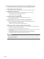
[Design Precautions]
DANGER
Configure safety circuits external to the programmable controller to ensure that the entire system
operates safely even when a fault occurs in the external power supply or the programmable
controller. Failure to do so may result in an accident due to an incorrect output or malfunction.
(1) Configure external safety circuits, such as an emergency stop circuit, protection circuit, and
protective interlock circuit for forward/reverse operation or upper/lower limit positioning.
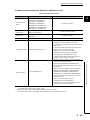
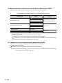
(2) The programmable controller stops its operation upon detection of the following status, and the
output status of the system will be as shown below.
Status
Overcurrent or overvoltage protection of
the power supply module is activated.
The CPU module detects an error such as
a watchdog timer error by the
self-diagnostic function.
Q series module
AnS/A series module
All outputs are turned off
All outputs are turned off
All outputs are held or
turned off according to the
All outputs are turned off
parameter setting.
All outputs may turn on when an error occurs in the part, such as I/O control part, where the CPU
module cannot detect any error. To ensure safety operation in such a case, provide a safety
mechanism or a fail-safe circuit external to the programmable controller. For a fail-safe circuit
example, refer to Chapter 10 LOADING AND INSTALLATION in the QCPU User's Manual
(Hardware Design, Maintenance and Inspection).
(3) Outputs may remain on or off due to a failure of an output module relay or transistor. Configure
an external circuit for monitoring output signals that could cause a serious accident.
A-2
[Design Precautions]
DANGER
In an output module, when a load current exceeding the rated current or an overcurrent caused by a
load short-circuit flows for a long time, it may cause smoke and fire. To prevent this, configure an
external safety circuit, such as a fuse.
Configure a circuit so that the programmable controller is turned on first and then the external power
supply.
If the external power supply is turned on first, an accident may occur due to an incorrect output or
malfunction.
For the operating status of each station after a communication failure, refer to relevant manuals for
the network.
Incorrect output or malfunction due to a communication failure may result in an accident.
When changing data of the running programmable controller from a peripheral connected to the
CPU module or from a personal computer connected to an intelligent function module, configure an
interlock circuit in the sequence program to ensure that the entire system will always operate safely.
For program modification and operating status change, read relevant manuals carefully and ensure
the safety before operation.
Especially, in the case of a control from an external device to a remote programmable controller,
immediate action cannot be taken for a problem on the programmable controller due to a
communication failure.
To prevent this, configure an interlock circuit in the sequence program, and determine corrective
actions to be taken between the external device and CPU module in case of a communication
failure.
CAUTION
Do not install the control lines or communication cables together with the main circuit lines or power
cables.
Keep a distance of 100mm (3.94 inches) or more between them.
Failure to do so may result in malfunction due to noise.
When a device such as a lamp, heater, or solenoid valve is controlled through an output module, a
large current (approximately ten times greater than normal) may flow when the output is turned from
off to on.
Take measures such as replacing the module with one having a sufficient current rating.
A-3
[Installation Precautions]
CAUTION
Use the programmable controller in an environment that meets the general specifications in the
QCPU User's Manual (Hardware Design, Maintenance and Inspection).
Failure to do so may result in electric shock, fire, malfunction, or damage to or deterioration of the
product.
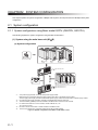
To mount the module, while pressing the module mounting lever located in the lower part of the
module, fully insert the module fixing projection(s) into the hole(s) in the base unit and press the
module until it snaps into place.
Incorrect mounting may cause malfunction, failure or drop of the module.
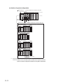
When using the programmable controller in an environment of frequent vibrations, fix the module
with a screw.
Tighten the screw within the specified torque range.
Undertightening can cause drop of the screw, short circuit or malfunction.
Overtightening can damage the screw and/or module, resulting in drop, short circuit, or malfunction.
When using an extension cable, connect it to the extension cable connector of the base unit securely.
Check the connection for looseness.
Poor contact may cause incorrect input or output.
When using a memory card, fully insert it into the memory card slot.
Check that it is inserted completely.
Poor contact may cause malfunction.
Shut off the external power supply for the system in all phases before mounting or removing the
module. Failure to do so may result in damage to the product.
A module can be replaced online (while power is on) on any MELSECNET/H remote I/O station or in
the system where a CPU module supporting the online module change function is used.
Note that there are restrictions on the modules that can be replaced online, and each module has its
predetermined replacement procedure.
For details, refer to the relevant sections in the QCPU User's Manual (Hardware Design,
Maintenance and Inspection) and in the manual for the corresponding module.
Do not directly touch any conductive part of the module.
Doing so can cause malfunction or failure of the module.
When using a Motion CPU module and modules designed for motion control, check that the
combinations of these modules are correct before applying power.
The modules may be damaged if the combination is incorrect.
For details, refer to the user's manual for the Motion CPU module.
A-4
[Wiring Precautions]
DANGER
Shut off the external power supply for the system in all phases before wiring.
Failure to do so may result in electric shock or damage to the product.
After wiring, attach the included terminal cover to the module before turning it on for operation.
Failure to do so may result in electric shock.
DANGER
Ground the FG and LG terminals to the protective ground conductor dedicated to the programmable
controller.
Failure to do so may result in electric shock or malfunction.
Use applicable solderless terminals and tighten them within the specified torque range. If any spade
solderless terminal is used, it may be disconnected when the terminal screw comes loose, resulting
in failure.
Check the rated voltage and terminal layout before wiring to the module, and connect the cables
correctly.
Connecting a power supply with a different voltage rating or incorrect wiring may cause a fire or
failure.
Connectors for external connection must be crimped or pressed with the tool specified by the
manufacturer, or must be correctly soldered.
Incomplete connections could result in short circuit, fire, or malfunction.
Tighten the terminal screw within the specified torque range.
Undertightening can cause short circuit, fire, or malfunction.
Overtightening can damage the screw and/or module, resulting in drop, short circuit, or malfunction.
Prevent foreign matter such as dust or wire chips from entering the module.
Such foreign matter can cause a fire, failure, or malfunction.
A-5
[Wiring Precautions]
DANGER
A protective film is attached to the top of the module to prevent foreign matter, such as wire chips,
from entering the module during wiring.
Do not remove the film during wiring.
Remove it for heat dissipation before system operation.
Mitsubishi programmable controllers must be installed in control panels.
Connect the main power supply to the power supply module in the control panel through a relay
terminal block.
Wiring and replacement of a power supply module must be performed by maintenance personnel
who is familiar with protection against electric shock. (For wiring methods, refer to the QCPU User's
Manual (Hardware Design, Maintenance and Inspection)).
[Startup and Maintenance Precautions]
DANGER
Do not touch any terminal while power is on.
Doing so will cause electric shock.
Correctly connect the battery connector.
Do not charge, disassemble, heat, short-circuit, solder, or throw the battery into the fire.
Doing so will cause the battery to produce heat, explode, or ignite, resulting in injury and fire.
Shut off the external power supply for the system in all phases before cleaning the module or
retightening the terminal screws or module fixing screws.
Failure to do so may result in electric shock.
Undertightening the terminal screws can cause short circuit or malfunction.
Overtightening can damage the screw and/or module, resulting in drop, short circuit, or malfunction.
A-6
[Startup and Maintenance Precautions]
CAUTION
Before performing online operations (especially, program modification, forced output, and operation
status change) for the running CPU module from the peripheral connected, read relevant manuals
carefully and ensure the safety.
Improper operation may damage machines or cause accidents.
Do not disassemble or modify the modules.
Doing so may cause failure, malfunction, injury, or a fire.
Use any radio communication device such as a cellular phone or PHS (Personal Handy-phone
System) more than 25cm (9.85 inches) away in all directions from the programmable controller.
Failure to do so may cause malfunction.
Shut off the external power supply for the system in all phases before mounting or removing the
module. Failure to do so may cause the module to fail or malfunction.
A module can be replaced online (while power is on) on any MELSECNET/H remote I/O station or in
the system where a CPU module supporting the online module change function is used.
Note that there are restrictions on the modules that can be replaced online, and each module has its
predetermined replacement procedure.
For details, refer to the relevant sections in the QCPU User's Manual (Hardware Design,
Maintenance and Inspection) and in the manual for the corresponding module.
After the first use of the product, do not mount/remove the module to/from the base unit, and the
terminal block to/from the module more than 50 times (IEC 61131-2 compliant) respectively.
Exceeding the limit of 50 times may cause malfunction.
Do not drop or apply shock to the battery to be installed in the module.
Doing so may damage the battery, causing the battery fluid to leak inside the battery.
If the battery is dropped or any shock is applied to it, dispose of it without using.
Before handling the module, touch a grounded metal object to discharge the static electricity from
the human body.
Failure to do so may cause the module to fail or malfunction.
A-7
[Disposal Precautions]
CAUTION
When disposing of this product, treat it as industrial waste.
When disposing of batteries, separate them from other wastes according to the local regulations.
(For details of the Battery Directive in EU countries, refer to the QCPU User's Manual (Hardware
Design, Maintenance and Inspection).)
[Transportation Precautions]
CAUTION
When transporting lithium batteries, follow the transportation regulations.
(For details of the regulated models, refer to the QCPU User's Manual (Hardware Design,
Maintenance and Inspection).)
A-8
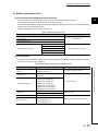
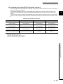
REVISIONS
*The manual number is given on the bottom left of the back cover.
Print date
Manual number
Revision
Jun., 2004
SH(NA)-080485ENG-A First edition
May, 2005
SH(NA)-080485ENG-B Partial correction
GENERIC TERMS AND ABBREVIATIONS, Chapter 1, Section 1.1, 2.1, 2.3, 2.4,
3.1, 3.3.1, 3.3.2, 3.4.1, 3.4.2, 3.8, 3.9, 3.10, 4.1.1, 4.1.2, 4.1.3, 6.1, 6.1.1, 7.1,
8.1, 8.2.2, 8.2.3, 8.2.4, 8.3.1, 8.3.4, Appendix 1.1
Aug., 2005
SH(NA)-080485ENG-C Partial correction
Apr., 2007
SH(NA)-080485ENG-D Universal model QCPU model addition
GENERIC TERMS AND ABBREVIATIONS, Section 2.1
Revision involving Universal model QCPU serial No.09012
Model addition
Q02UCPU, Q03UDCPU, Q04UDHCPU, Q06UDHCPU, Q61P, QA65B, QA68B
Partial correction
SAFETY PRECAUTION, ABOUT MANUALS, GENERIC TERMS AND
ABBREVIATIONS, Section 1.1, 1.2, 1.3, 2.1.1, 2.1.2, 2.1.3, 2.2, 2.3, 2.4, 3.1.1,
3.1.2, 3.1.3, Chapter 4, Section 4.1, 4.1.1, 4.1.2, 4.1.3, 4.1.4, 4.1.5, 4.3.2, 5.1,
5.2, 6.1, 6.1.3, 6.1.4, 6.1.7, 6.1.8, 7.1, 8.1, 8.2.1, 8.2.2
Aug., 2007
SH(NA)-080485ENG-E Model addition
QA6ADP
Partial correction
GENERIC TERMS AND ABBREVIATIONS, Section 1.1, 1.2, 1.3, 2.1.1, 2.1.2,
2.1.3, 2.2, 2.3, 3.1, 3.1.2, 3.1.3, 3.3.1, 3.8, 4.1, 4.1.2, 4.2.1, 4.3.1, 8.2.2,
Appendix 1.1
Mar., 2008
SH(NA)-080485ENG-F Universal model QCPU model addition
Model addition
Q13UDHCPU, Q26UDHCPU
Partial correction
GENERIC TERMS AND ABBREVIATIONS, Section 1.1.1, 1.2, 1.3, 2.1.1, 2.1.2,
2.1.3, 2.3, 2.4, 3.1, 3.1.1, 3.1.2, 3.1.3, Chapter 4, Section 4.1.2, 4.1.3, 4.1.4,
4.1.5, 4.2.1, 4.3.1, 4.4, 4.5, 5.1, 5.2, 5.3, 6.1, 6.1.8, 7.1, 8.1, 8.2.1, 8.2.2, 8.3.1,
8.3.2
Addition
Section 4.3.3
Japanese manual version SH-080475-H
This manual confers no industrial property rights or any rights of any other kind, nor does it confer any patent licenses. Mitsubishi Electric Corporation cannot be held responsible for any problems involving industrial property rights which may occur
as a result of using the contents noted in this manual.
2008 MITSUBISHI ELECTRIC CORPORATION
A-9
Print date
May, 2008
Manual number
Revision
SH(NA)-080485ENG-G Addition of Universal model QCPU and Process CPU models
Model addition
Q02PHCP, Q06PHCPU, Q03UDECPU, Q04UDEHCPU, Q06UDEHCPU,
Q13UDEHCPU, Q26UDEHCPU
Partial correction
A term "MELSECNET/G" has been revised to "CC-Link IE controller network"
through this manual,
GENERIC TERMS AND ABBREVIATIONS, Chapter 1, Section 1.1, 2.1.1,
2.1.2, 2.1.3, 2.2, 2.3, 2.4, 3.1, 3.8, 4.2, 4.3.1, 4.3.3, 5.1, 5.2, 6.1
Dec., 2008
SH(NA)-080485ENG-H Addition of Universal model QCPU and C Controller module
Model addition
Q00UCPU, Q01UCPU, Q10UDHCPU, Q20UDHCPU, Q10UDEHCPU,
Q20UDEHCPU, Q61P-D
Partial correction
ABOUT MANUALS, GENERIC TERMS AND ABBREVIATIONS, Chapter 1,
Section 1.1, 1.3, 2.1.1, 2.1.2, 2.1.3, 2.3, 2.4, 3.1, 3.1.2, 3.1.3, 3.2, 3.3.2, 3.7, 3.9,
4.1.1, 4.1.2, 4.1.3, 4.1.4, 4.1.5, 4.3.1, 4.3.3, 4.5, 5.1, 5.2, 7.1, 8.1, 8.2.2
A - 10
INTRODUCTION
This manual is designed for users to understand the multiple CPU system including information of the system
configuration, functions, and communication with external devices that are required when the MELSEC-Q
series programmable controller is used in the multiple CPU system.
This manual is composed of the following parts and explains:
1) Chapter 1 and 2
Overview and system configuration of the multiple CPU system
2) Chapter 3
Multiple CPU system concept
3) Chapter 4
Communications between CPU modules in the multiple CPU system
4) Chapter 5
Processing time in the multiple CPU system
5) Chapter 6
Parameters used in the multiple CPU system
6) Chapter 7
Precautions for use of the AnS series module in the multiple CPU system
7) Chapter 8
Startup of the multiple CPU system
Before using the equipment, please read this manual carefully to develop full familiarity with the functions and
performance of the Q series programmable controller you have purchased, so as to ensure correct use.
Relevant CPU module
CPU module
Model
Basic model QCPU
Q00CPU, Q01CPU
High Performance model QCPU
Q02CPU, Q02HCPU, Q06HCPU, Q12HCPU, Q25HCPU
Process CPU
Q02PHCPU, Q06PHCPU, Q12PHCPU, Q25PHCPU
Q00UCPU, Q01UCPU, Q02UCPU, Q03UDCPU, Q04UDHCPU,
Universal model QCPU
Q06UDHCPU, Q10UDHCPU, Q13UDHCPU, Q20UDHCPU,
Q26UDHCPU, Q03UDECPU, Q04UDEHCPU, Q06UDEHCPU,
Q10UDEHCPU, Q13UDEHCPU, Q20UDEHCPU, Q26UDEHCPU
Remark
This manual does not include the specifications of the power supply module, base unit, extension cables, memory cards
and batteries.
Refer to the following manual.
QCPU User's Manual (Hardware Design, Maintenance and Inspection)
This manual does not describe the functions of the CPU module.
For the functions, refer to the following.
Manuals for the CPU module used. (Function Explanation, Program Fundamentals)
A - 11
CONTENTS
CONTENTS
SAFETY PRECAUTIONS...................................................................................................................... A - 1
REVISIONS ........................................................................................................................................... A - 9
INTRODUCTION ................................................................................................................................... A - 11
MANUALS ............................................................................................................................................. A - 15
MANUAL PAGE ORGANIZATION ......................................................................................................... A - 18
GENERIC TERMS AND ABBREVIATIONS .......................................................................................... A - 20
CHAPTER1 OUTLINE
1-1 to 1-23
1.1
What is multiple CPU system?............................................................................................... 1 - 1
1.2
Features of multiple CPU system .......................................................................................... 1 - 5
1.3
Difference from Single CPU System...................................................................................... 1 - 11
CHAPTER2 SYSTEM CONFIGURATION
2.1
2-1 to 2-57
System configuration ............................................................................................................. 2 - 1
2.1.1
System configuration using Basic model QCPU (Q00CPU, Q01CPU) ............................. 2 - 1
2.1.2
System configuration using High Performance model QCPU or Process CPU as
CPU No.1 ........................................................................................................ 2 - 10
2.1.3
System configuration using Universal model QCPU as CPU No.1 ................................... 2 - 24
2.2
Configuration of peripheral devices ....................................................................................... 2 - 38
2.3
Configurable device and available software .......................................................................... 2 - 42
2.4
Precautions for system configuration..................................................................................... 2 - 52
CHAPTER3 CONCEPT FOR MULTIPLE CPU SYSTEM
3.1
3.2
3.3
3.4
3-1 to 3-41
Mounting Position of CPU Module ......................................................................................... 3 - 1
3.1.1
When CPU No.1 is Basic model QCPU ............................................................................ 3 - 2
3.1.2
When CPU No.1 is High Performance model QCPU or Process CPU ............................. 3 - 6
3.1.3
When CPU No.1 is Universal model QCPU ...................................................................... 3 - 11
CPU No. of CPU module ....................................................................................................... 3 - 18
Concept of I/O number assignment ....................................................................................... 3 - 20
3.3.1
I/O number assignment of each module ........................................................................... 3 - 20
3.3.2
I/O number of each CPU module ...................................................................................... 3 - 22
Access Range of CPU Module and Other Modules............................................................... 3 - 23
3.4.1
Access range with controlled module................................................................................ 3 - 23
3.4.2
Access range with non-controlled module ........................................................................ 3 - 23
3.5
Access target under GOT connection.................................................................................... 3 - 30
3.6
Access with instruction using link direct device ..................................................................... 3 - 30
3.7
Access range of GX Developer.............................................................................................. 3 - 31
3.8
3.9
Clock data used by CPU module and intelligent function module ......................................... 3 - 34
3.8.1
Clock data used by CPU module ...................................................................................... 3 - 34
3.8.2
Clock data used by intelligent function module ................................................................. 3 - 35
Resetting the multiple CPU system ....................................................................................... 3 - 36
3.10 Operation for CPU module stop error .................................................................................... 3 - 37
3.11 Host CPU number of multiple CPU system ........................................................................... 3 - 40
A - 12
CHAPTER4 COMMUNICATIONS BETWEEN CPU MODULES
4.1
4.2
Communications between CPU modules using CPU shared memory .................................. 4 - 3
4.1.1
CPU shared memory......................................................................................................... 4 - 3
4.1.2
Communication by auto refresh using CPU shared memory ............................................ 4 - 8
4.1.3
Communication by auto refresh using multiple CPU high speed transmission area......... 4 - 23
4.1.4
Communication using CPU shared memory by program .................................................. 4 - 36
4.1.5
Communications between CPU modules when the error occurs ...................................... 4 - 46
Communications with instructions dedicated to Motion CPU................................................. 4 - 47
4.2.1
4.3
4-1 to 4-56
Control instruction from QCPU to Motion CPU ................................................................. 4 - 47
Communication with Dedicated Instructions .......................................................................... 4 - 49
4.3.1
Writing/reading of device data from QCPU to Motion CPU............................................... 4 - 49
4.3.2
Starting interrupt program from QCPU to C Controller module/PC CPU module.............. 4 - 51
4.3.3
Writing/reading of device data from QCPU to QCPU........................................................ 4 - 52
4.4
Multiple CPU Synchronous Interrupt...................................................................................... 4 - 53
4.5
Multiple CPU Synchronized Boot-up...................................................................................... 4 - 55
CHAPTER5 PROCESSING TIME OF QCPU IN MULTIPLE CPU SYSTEM 5-1 to 5-10
5.1
Concept of Scan Time ........................................................................................................... 5 - 1
5.2
Factors for prolonged Scan Time........................................................................................... 5 - 3
5.3
Reducing processing time...................................................................................................... 5 - 10
CHAPTER6 PARAMETER ADDED FOR MULTIPLE CPU SYSTEM
6.1
6-1 to 6-9
Parameter list......................................................................................................................... 6 - 1
6.1.1
Number of CPUs setting ................................................................................................... 6 - 6
6.1.2
Operating mode setting ..................................................................................................... 6 - 8
6.1.3
Online module change setting........................................................................................... 6 - 8
6.1.4
I/O settings outside of the group ....................................................................................... 6 - 8
6.1.5
Communication area setting (Refresh setting) .................................................................. 6 - 8
6.1.6
Control CPU settings......................................................................................................... 6 - 9
6.1.7
Multiple CPU synchronized boot-up.................................................................................. 6 - 9
6.1.8
Multiple CPU high speed transmission area setting.......................................................... 6 - 9
CHAPTER7 PRECAUTIONS FOR USING AnS/A SERIES-COMPATIBLE MODULES
7-1 to 7-4
7.1
Precautions for use of AnS/A series compatible module ....................................................... 7 - 1
CHAPTER8 STARTING UP THE MULTIPLE CPU SYSTEM
8-1 to 8-39
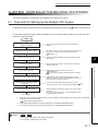
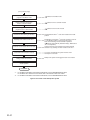
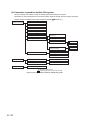
8.1
Flow-chart for Starting Up the Multiple CPU System ............................................................. 8 - 1
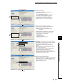
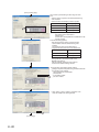
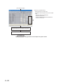
8.2
Setting Up the Multiple CPU System Parameters.................................................................. 8 - 3
A - 13
8.2.1
Parameter setting for the Basic model QCPU,High Paformance model QCPU,
Process CPU.................................................................................................... 8 - 3
8.3
8.2.2
Parameter setting for the Universal model QCPU ............................................................ 8 - 15
8.2.3
Reusing preset multiple CPU parameters ......................................................................... 8 - 23
Communication program examples using auto refresh ......................................................... 8 - 28
8.3.1
Program examples for the Basic model QCPU, High Performance model QCPU and
Process CPU.................................................................................................... 8 - 28
8.3.2
INDEX
A - 14
Program examples for the Universal model QCPU........................................................... 8 - 34
Index-1 to Index-2
MANUALS
To understand the main specifications, functions, and usage of the CPU module, refer to the basic manuals.
Read other manuals as well when using a different type of CPU module and its functions.
Order each manual as needed, referring to the following lists.
The numbers in the "CPU module" and the respective modules are as follows.
Number
CPU module
1)
Basic model QCPU
2)
High Performance model QCPU
3)
Process CPU
4)
Universal model QCPU
: Basic manual,
Manual name
< Manual number (model code) >
Description
: Other CPU module manuals
CPU module
1)
2)
3)
4)
User's manual
Specifications of the hardware (CPU
QCPU User's Manual (Hardware Design, Mainte- modules, power supply modules, base units,
nance and Inspection)
extension cables, and memory cards), sys< SH-080483ENG (13JR73) > tem maintenance and inspection, troubleshooting, and error codes
QnUCPU Users Manual (Function Explanation,
Program Fundamentals)
< SH-080807ENG (13JZ27) >
Qn(H)/QnPH/QnPRHCPU User's Manual (Function Explanation, Program Fundamentals)
< SH-080808ENG (13JZ28) >
Functions, methods, and devices for
programming
Functions, methods, and devices for
programming
Information for configuring a multiple CPU
system (system configuration, I/O
QCPU User's Manual (Multiple CPU System)
numbers, communication between CPU
< SH-080485ENG (13JR75) > modules, and communication with the input/
output modules and intelligent function modules)
QnUCPU User's Manual (Communication via
Built-in Ethernet Port)
< SH-080811ENG (13JZ29) >
Functions for the communication via built-in
Ethernet port of the CPU module
Programming manual
QCPU Programming Manual (Common Instructions)
< SH-080809ENG (13JW10) >
How to use sequence instructions, basic
instructions, and application instructions
System configuration, performance
specifications, functions, programming,
debugging, and error codes for SFC
< SH-080041 (13JF60) >
(MELSAP3) programs
QCPU (Q Mode)/QnACPU Programming
Manual (SFC)
QCPU (Q Mode) Programming Manual
(MELSAP-L)
< SH-080076 (13JF61) >
Programming methods, specifications, and
functions for SFC (MELSAP-L) programs
A - 15
Manual name
< Manual number (model code) >
QCPU (Q Mode) Programming Manual
(Structured Text)
< SH-080366E (13JF68) >
QCPU (Q Mode) / QnACPU Programming Manual (PID Control Instructions)
Description
Programming methods using structured languages
Dedicated instructions for PID control
< SH-080040 (13JF59) >
QnPHCPU/QnPRHCPU Programming Manual
(Process Control Instructions)
< SH-080316E (13JF67) >
A - 16
Dedicated instructions for process control
CPU module
1)
2)
3)
4)
Other relevant manuals
Manual name
CC-Link IE Controller Network Reference
Manual
Description
Specifications, procedures and settings before system operation, parameter
setting, programming, and troubleshooting of the CC-Link IE controller
< SH-080668ENG (13JV16) > network module
Q Corresponding MELSECNET/H Network
Specifications, procedures and settings before system operation, parameter
System Reference Manual (PLC to PLC
setting, programming, and troubleshooting of a MELSECNET/H network
network)
system (PLC to PLC network)
< SH-080049 (13JF92) >
Q Corresponding MELSECNET/H Network
System Reference Manual (Remote I/O
network)
< SH-080124 (13JF96) >
Specifications, procedures and settings before system operation, parameter
setting, programming, and troubleshooting of a MELSECNET/H network
system (remote I/O network)
Q Corresponding Ethernet Interface Module
User's Manual (Basic)
Specifications, procedures for data communication with external devices,
line connection (open/close), fixed buffer communication, random access
< SH-080009 (13JL88) > buffer communication, and troubleshooting of the Ethernet module
E-mail function, programmable controller CPU status monitoring function,
Q Corresponding Ethernet Interface Module
communication via MELSECNET/H or MELSECNET/10, communication
User's Manual (Application)
using the data link instructions, and file transfer function (FTP server) of the
< SH-080010 (13JL89) >
Ethernet module
CC-Link System Master/Local Module User's
System configuration, performance specifications, functions, handling,
Manual
wiring, and troubleshooting of the QJ61BT11N
< SH-080394E (13JR64) >
Overview, system configuration, specifications, procedures before
operation, basic data communication method with external devices,
maintenance and inspection, and troubleshooting for using the serial
< SH-080006 (13JL86) >
communication module
Q Corresponding Serial Communication
Special functions (specifications, usage, and settings and data
Module User's Manual (Application)
communication method with external devices of the serial communication
Q Corresponding Serial Communication
Module User's Manual (Basic)
< SH-080007 (13JL87) > module
Q Corresponding MELSEC Communication
Protocol Reference Manual
Communication method using the MC protocol, which reads/writes data to/
from the CPU module via the serial communication module or Ethernet
< SH-080008 (13JF89) > module
GX Developer Version 8 Operating Manual
Operating methods of GX Developer, such as programming and printout
< SH-080373E (13JU41) >
A - 17
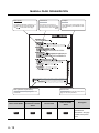
MANUAL PAGE ORGANIZATION
Note (icon)
Reference
The section in this manual or
another relevant manual that can
be referred to is shown with
.
The detailed explanation of "Note . " is
provided under the corresponding
"Note . " at the bottom of the page.
Chapter
The chapter of the current page can be
easily identified by this indication on the
right side.
Note (detailed explanation)
Section title
The detailed note corresponding to each icon
is described.
The section number and title of the current
page can be easily identified.
Icons
High
Basic model QCPU
Performance model
Process CPU
QCPU
Basic
A - 18
High
performance
Process
Universal model
Description
QCPU
Universal
Icons indicate that
specifications
described on the page
contain some precautions.
In addition, this manual uses the following types of explanations.
In addition to description of the page, notes or functions that require special attention are described here.
Remark
The reference related to the page or useful information are described here.
A - 19
GENERIC TERMS AND ABBREVIATIONS
Unless otherwise specified, this manual uses the following generic terms and abbreviations.
*
indicates a part of the model or version.
(Example): Q33B, Q35B, Q38B, Q312B
Q3
B
Generic term/abbreviation
Description
Series
Q series
Abbreviation for Mitsubishi MELSEC-Q series programmable controller
AnS series
Generic term for compact types of Mitsubishi MELSEC-A Series Programmable
Controller
A series
Generic term for large types of Mitsubishi MELSEC-A Series Programmable
Controller
CPU module type
CPU module
Generic term for the Basic model QCPU, High Performance model QCPU,
Process CPU, Redundant CPU, Universal model QCPU
Basic model QCPU
Generic term for the Q00CPU, and Q01CPU
High Performance model QCPU
Generic term for the Q02CPU, Q02HCPU, Q06HCPU, Q12HCPU, Q25HCPU
Process CPU
Generic term for the Q02PHCPU, Q06PHCPU, Q12PHCPU, Q25PHCPU
Universal model QCPU
Generic term for the Q00UCPU, Q01UCPU, Q02UCPU, Q03UDCPU,
Q04UDHCPU, Q06UDHCPU, Q10UDHCPU, Q13UDHCPU, Q20UDHCPU,
Q26UDHCPU, Q03UDECPU, Q04UDEHCPU, Q06UDEHCPU, Q10UDEHCPU,
Q13UDEHCPU, Q20UDEHCPU, and Q26UDEHCPU
Built-in Ethernet port QCPU
Generic term for the Q03UDECPU, Q04UDEHCPU, Q06UDEHCPU,
Q10UDEHCPU, Q13UDEHCPU, Q20UDEHCPU, and Q26UDEHCPU
Motion CPU
Generic term for Mitsubishi motion controllers, Q172CPUN, Q173CPUN,
Q172HCPU, Q173HCPU, Q172CPUN-T, Q173CPUN-T, Q172HCPU-T,
Q173HCPU-T, Q172DCPU, and Q173DCPU
PC CPU module
C Controller module
Generic term for MELSEC-Q series-compatible PC CPU module,
PPC-CPU686(MS)-64, PPC-CPU686(MS)-128, PPC-CPU852(MS)-512,
manufactured by CONTEC Co., Ltd.
Generic term for the Q06CCPU-V, Q06CCPU-V-B C Controller modules
CPU module model
QnU(D)(H)CPU
Generic term for the Q00UCPU, Q01UCPU, Q02UCPU, Q03UDCPU,
Q04UDHCPU, Q06UDHCPU, Q10UDHCPU, Q13UDHCPU, Q20UDHCPU, and
Q26UDHCPU
Base unit type
Base unit
Generic term for the main base unit, extension base unit, slim type main base
unit, redundant power main base unit, redundant type extension base unit, and
multiple CPU high speed main base unit
Main base unit
Generic term for the Q3 B, Q3 SB, Q3 RB, and Q3 DB
Extension base unit
Generic term for the Q5 B, Q6 B, Q6 RB, Q6
and QA6ADP+A5
B/A6
B
Slim type main base unit
Another name for the Q3
SB
Redundant power main base unit
Another name for the Q3
RB
Redundant power extension base
unit
Another name for the Q6
RB
A - 20
WRB, QA1S6 B, QA6 B,
Generic term/abbreviation
Multiple CPU high speed main
base unit
Description
Another name for the Q3 DB
Base unit model
Q3 B
Generic term for the Q33B, Q35B, Q38B, and Q312B main base units
Q3 SB
Generic term for the Q32SB, Q33SB, and Q35SB slim type main base units
Q3 RB
Another name for the Q38RB redundant power main base unit
Q3 DB
Generic term for the Q38DB and Q312DB multiple CPU high speed main base units
Q5 B
Generic term for the Q52B and Q55B extension base units
Q6 B
Generic term for the Q63B, Q65B, Q68B, and Q612B extension base units
Q6 RB
Another name for the Q68RB redundant power extension base unit
QA1S6 B
Generic term for the QA1S65B and QA1S68B
QA6 B
Generic term for the QA65B and QA68B extension base units
A5 B
Generic term for the A52B, A55B, and A58B extension base units
A6 B
Generic term for the A62B, A65B, and A68B extension base units
QA6ADP+A5 B/A6 B
Abbreviation for a large type extension base unit where the QA6ADP is mounted
Power supply module
Power supply module
Generic term for the Q series power supply module, slim type power supply module, and redundant power supply module
Q series power supply module
Generic term for the Q61P-A1, Q61P-A2, Q61P, Q61P-D, Q62P, Q63P, Q64P, and
Q64PN power supply modules
Slim type power supply module
Abbreviation for the Q61SP slim type power supply module
AnS series power supply module
Generic term for the A1S61PN, A1S62PN, and A1S63 power supply modules
A series power supply module
Generic term for the A61P, A61PN, A62P, A63P, A68P, A61PEU, and A62PEU
power supply modules
Redundant power supply module
Generic term for the Q63RP and Q64RP redundant power supply modules
Network
MELSECNET/H
Abbreviation for the MELSECNET/H network system
Ethernet
Abbreviation for the Ethernet network system
CC-Link
Abbreviation for the Control & Communication Link
Memory card
Memory card
Generic term for the SRAM card, Flash card, and ATA card
SRAM card
Generic term for the Q2MEM-1MBS, Q2MEM-2MBS, Q3MEM-4MBS, and
Q3MEM-8MBS SRAM cards
Flash card
Generic term for the Q2MEM-2MBF and Q2MEM-4MBF Flash cards
ATA card
Generic term for the Q2MEM-8MBA, Q2MEM-16MBA, and Q2MEM-32MBA ATA
cards
Others
GX Developer
Product name for SW D5C-GPPW-E GPP function software package compatible
with the Q series
PX Developer
Product name for SW D5C-FBDQ process control FBD software package
QA6ADP
Abbreviation for the QA6ADP QA conversion adapter module
A - 21
Generic term/abbreviation
Description
Extension cable
Generic term for the QC05B, QC06B, QC12B, QC30B, QC50B, and QC100B
extension cables
Tracking cable
Generic term for the QC10TR and QC30TR tracking cables for the Redundant
module
Battery
Generic term for the Q6BAT, Q7BAT, and Q8BAT CPU module batteries,
Q2MEM-BAT, SRAM card battery, and Q3MEM-BAT SRAM card battery
GOT
Generic term for Mitsubishi Graphic Operation Terminal, GOT-A*** series, GOT-F***
series, and GOT1000 series
A - 22
CHAPTER1 OUTLINE
CHAPTER1 OUTLINE
1
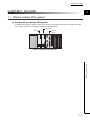
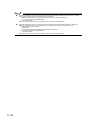
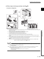
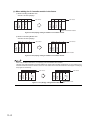
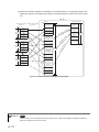
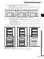
1.1 What is multiple CPU system?
2
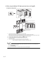
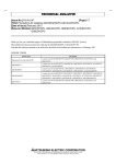
(1) Configuration of multiple CPU system
A multiple CPU system is a system in which more than one CPU module are mounted on several a main base
3
unit in order to control the I/O modules and intelligent function modules.
Motion CPU
QCPU
4
PC CPU
module
5
6
7
Figure 1.1 Configuration of multiple CPU
8
1.1 What is multiple CPU system?
1-1
(2) Available CPU modules in multiple CPU system
Table1.1 shows the available CPU modules in multiple CPU system.
Refer to Section 2.3 for the compatible version of each module.
Table1.1 Applicable CPU modules
CPU module
Basic model QCPU
High Performance model QCPU
Q
Process CPU
C
Model
Q00CPU, Q01CPU
Q02CPU,Q02HCPU,Q06HCPU,Q12HCPU,
Q25HCPU
Q02PHCPU,Q06PHCPU,Q12PHCPU,Q25PHCPU
Q00UCPU,Q01UCPU,Q02UCPU,Q03UDCPU,
P
Q04UDHCPU,Q06UDHCPU,Q10UDHCPU,
U
Universal model QCPU
Q13UDHCPU,Q20UDHCPU,Q26UDHCPU,
Q03UDECPU,Q04UDEHCPU,Q06UDEHCPU,
Q10UDEHCPU,Q13UDEHCPU,Q20UDEHCPU,
Q26UDEHCPU
Q172CPUN,Q173CPUN,Q172HCPU,Q173HCPU,
Motion CPU
Q172CPUN-T,Q173CPUN-T,Q172HCPU-T,
Q173HCPU-T
Q172DCPU,Q173DCPU
C Controller module
PC CPU module
(manufactured by CONTEC CO., LTD.*1)
Q06CCPU-V,Q06CCPU-V-B
PPC-CPU686(MS)-64,
PPC-CPU686(MS)-128,
PPC-CPU852(MS)-512
Choose the CPU modules suitable for the system size and application to configure the system.
Some combinations of CPU modules in Table 1.1 cannot be used.
Refer to Section 3.1 for combinations of configurable CPU modules.
*1:
For further information on PC CPU module, consult CONTEC Co.,Ltd.
Tel:+81-6-6472-7130
Remark
For details of the Motion CPU, C Controller module, and PC CPU module, refer to the manuals of each CPU module.
1-2
CHAPTER1 OUTLINE
1
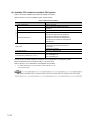
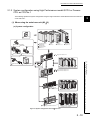
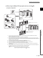
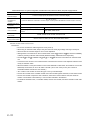
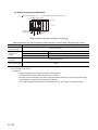
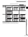
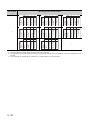
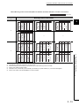
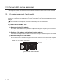
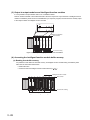
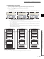
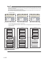
(3) Method for controlling I/O module and intelligent function module
It is necessary to set (control CPU setup) which CPU modules are to control which I/O modules and intelligent
function modules with a multiple CPU system.
CPU
0
1
2
3
2
4
5
6
7
Slot number
3
4
1
2
1
1
1
1
2
2
2
Control CPU setting
*2
5
Control with CPU module 1.
Control with CPU module 2.
Figure 1.2 Setting of control CPU
*2:
Indicates the grouping configuration on the GX Developer.
"1" on the CPU module indicates "CPU No.1," and "1" on the I/O module and intelligent function module indicates that
their "Control CPU is the CPU No.1."
6
7
The CPU module that controls the I/O modules and intelligent function modules is called as a "Control CPU".
The I/O modules and intelligent function modules controlled by the control CPU are called "controlled modules".
Other modules not controlled by the control CPU are called as "non-controlled modules".
8
1.1 What is multiple CPU system?
1-3
(4) Multiple CPU system setting
For control in the multiple CPU system, it is necessary to set up the "Number of mounted CPU modules" and the
"Control CPU" with PLC parameter for all CPU modules mounted on the main base unit.
User's Manual (Function Explanation, Program Fundamentals) for the CPU module used
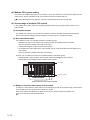
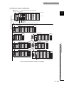
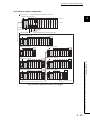
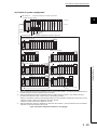
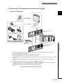
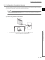
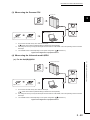
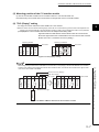
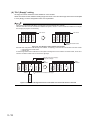
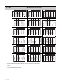
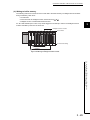
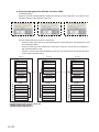
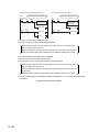
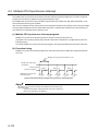
(5) Access range of multiple CPU system
In the multiple CPU system, the access ranges are different between the controlled module and the non-controlled module.
(a) Controlled module
The multiple CPU system's control CPU can refresh the I/O data of controlled modules and read/write the
buffer memory data of intelligent function modules in the same way as in a single CPU system.
(b) Non-controlled module
It is possible to access non-controlled modules in the following ways.
• Refreshing the input for I/O modules, I/O composite module and intelligent function modules
(the PLC parameter's multiple CPU setup is necessary.)
• Reading the intelligent function module's buffer memory.
• Downloading the output data from the output module, the I/O composite module and the intelligent function modules.
(the PLC parameter's multiple CPU setup is necessary.)
However, it is not possible to access non-controlled modules in the following ways.
• Outputting data to output modules, I/O composite module and intelligent function modules.
• Writing data into the intelligent function module's buffer memory.
CPU
0
1
2
3
4
5
6
7
Slot number
1
2
1
1
1
1
2
2
2
Control CPU setting
Readable with CPU module 2.
Readable with CPU module 1.
Figure 1.3 Access to non-controlled module
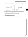
(c) Range of access to other station's CPU module
To access to a CPU module on other station from GX Developer, access can be made through a network module controlled by any CPU module in the multiple CPU system.
When other station has multiple CPUs, specifying the CPU No. allows access to the desired CPU.
User's manual for each network module
1-4
CHAPTER1 OUTLINE
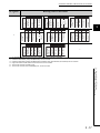
1.2 Features of multiple CPU system
1
(1) Multi-control system
2
(a) Configuration optimum for system
Since each system uses not only one QCPU but any combinations of the QCPU, Motion CPU, and PC CPU
module according to the system, the development efficiency and ease of maintenance of the system can be
enhanced.
(b) Module control
Each CPU module in the multiple CPU system controls the I/O module and intelligent function module on the
3
4
base unit by each slot.
GX Developer groups the I/O modules and intelligent function modules controlled by each CPU module in the
multiple CPU system.
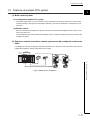
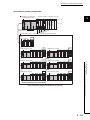
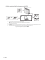
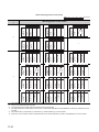
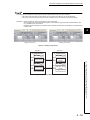
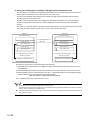
(2) Sequence control and motion control systems can be configured on the same
base.
In a Multiple CPU System consisting of the QCPU and Motion CPU, sequence control and motion control can be
implemented together to achieve a high-level motion system.
5
6
7
Control
Sequence
control
Motion control
8
Operation switch Operation status display
Servo
amplifier
Servo
amplifier
1.2 Features of multiple CPU system
SSCNET
Servomotor
Servomotor
Figure 1.4 Motion system configuration
1-5
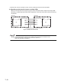
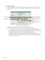
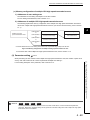
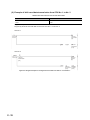
Interaction with a motion controller for motion control is enhanced in the Universal model QCPU.
(a) Speeding up data transfer between multiple CPUs
Maximum 14 k word-data and a sequence program can be transferred between multiple CPUs with parallel
processing. It enables high-speed data transfer independent of scan time, which leads to takt time shortening
of equipment.
CPU No.1
CPU No.2
Sequence program
X0
Y20
0
Multiple CPU high
speed transmission
Multiple CPU high Sequence program
X100
speed transmission
Data transfer
Y120
0
Data transfer
Data transfer
END
END
Parallel processing with a sequence program
Figure 1.5 Multiple CPU data transfer
Speeding up data transfer between multiple CPUs is available when the following CPU modules are used.
• Universal model QCPU (except Q00UCPU, Q01UCPU, Q02UCPU )
• Motion CPU (Q172DCPU, Q173DCPU )
1-6
CHAPTER1 OUTLINE
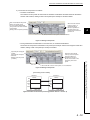
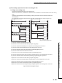
(b) Enabling synchronous processing with a motion control
An interrupt program which is synchronized with the operation cycle of a motion controller (multiple CPU syn-
1
chronous interrupt program) can be executed.
Command I/O from a motion controller can be synchronized with the operation cycle of the motion controller,
2
which enables high-speed data transfer independent of scan time.
Motion
controller
Operation cycle
of a motion
controller
3
Reading an
imposition signal
4
Motion SFC program
Multiple CPU high
speed transmission
area
5
Multiple CPU high
speed transmission
Universal
model QCPU Multiple CPU high
speed transmission
area
6
END 0
END 0
Sequence program
Multiple CPU
synchronous
interrupt program
7
I45 IRET
I45 IRET
Multiple CPU
high speed
transmission
cycle
I45 IRET
I45 IRET
I45 IRET
I45 IRET
Reading an
imposition signal
Reading an imposition
signal when multiple CPU
synchronous interrupt
program is not used
8
Figure 1.6 Reading data using multiple CPU synchronous interrupt program
1.2 Features of multiple CPU system
The synchronous processing with the Motion CPU is available when the following CPU modules are used.
• Universal model QCPU (except Q00UCPU, Q01UCPU, Q02UCPU )
• Motion CPU (Q172DCPU, Q173DCPU )
1-7
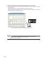
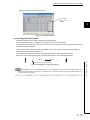
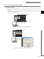
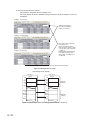
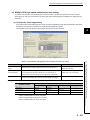
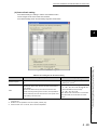
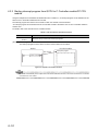
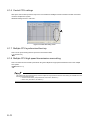
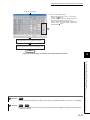
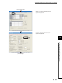
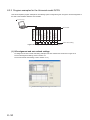
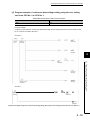
(c) Timing of data send/receive between the CPU modules can be checked
The sampling trace function of the Universal model QCPU enables to check the data send/receive timing with
the Motion controller.
(Timing of data send/receive can be checked between the Universal model QCPUs.)
Using the sampling trace function facilitates to check the data send/receive timing between CPU modules, and
reduces the debug time of the multiple CPU system.
Sampling trace result display by GX Developer
Figure 1.7 Sampling trace at the time of configuring multiple CPU system
The sampling trace of the other CPU module data can be executed, specifying the following CPU modules.
• Universal model QCPU (except Q00UCPU, Q01UCPU, Q02UCPU )
• Motion CPU (Q172DCPU, Q173DCPU )
1-8
CHAPTER1 OUTLINE
1
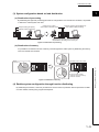
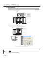
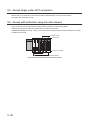
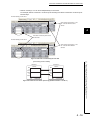
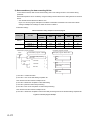
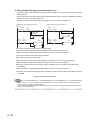
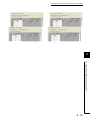
(3) System configuration based on load distribution.
(a) Distribution of processing
By distributing the high-load processing performed on a single QCPU over several CPU modules, it is possible
2
to reduce the overall system scan time.
(Control in 1ms or less)
Data processing (low speed)
Machine control (high speed)
QJ71C24-R2
CH.1
RUNERR.
NEUNEU
SD SD CH.2
RD RD
QD75P1
RUN
3
(Control in several to several dozen ms)
CPU module for machine control
CPU module for data processing
QD75P1
RUN
AX1
AX1
QJ71C24-R2
CH.1
ERR
ERR
4
RUNERR.
NEUNEU
SD SD CH.2
RD RD
AX1
AX1
CH. 1
CH. 1
All controls are executed with one QCPU.
5
Machine control speed is further increased with
load distribution according to the control cycle.
Figure 1.8 Distribution of processing
6
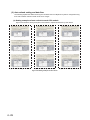
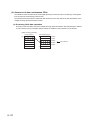
(b) Distribution of memory
It is possible to increase the amount of memory used throughout the entire system by distributing the memory
used over several CPU modules.
7
Empty
memory
Used
memory
Empty
memory
Extendable for each CPU module.
Used
memory
Empty
memory
One CPU module is added.
Extension of program memory
Extension of device
Figure 1.9 Distribution of memory
(4) Enables system configuration through function distributing
By distributing the functions, control for production line A and control for production line B is performed on different CPU modules, allowing easy program development.
1-9
1.2 Features of multiple CPU system
Used
memory
8
(5) Communication between CPU modules in the multiple CPU system
The following data transfer can be made between CPU modules in the multiple CPU system.
(a) Data transfer between CPU modules
The following data transfer can be made between CPU modules in the multiple CPU system.
(b) Reading data in another CPU
The QCPU can read data in another CPU with the following instruction when necessary.
• The read instruction from another CPU shared memory
• Multiple CPU shared device (U3En\G
)
(c) Control direction to the Motion CPU
The QCPU can direct control to the Motion CPU with the following instruction.
• Motion dedicated instruction*1
(d) Writing/reading device data from the QCPU to the Motion CPU
The QCPU can write/read device data to/from the Motion CPU with the following instructions.
• Multiple CPU transmission dedicated instruction*2
• Multiple CPU high-speed transmission dedicated instruction*3
(e) Event issue to the C Controller module or PC CPU module
The QCPU can issue an event to the C Controller module or PC CPU module with the following instruction.
• Multiple CPU transmission dedicated instruction*2
*1:
*2:
*3:
Refer to the manual of the Motion CPU for instructions dedicated to Motion.
For the multiple CPU transmission dedicated instruction, refer to the manuals of the Motion CPU, C Controller module,
and PC CPU module.
For the multiple CPU high-speed transmission dedicated instruction, refer to the following manuals.
Writing/reading device data to/from the QCPU: QCPU Programming Manual (Common Instructions)
Writing/reading device data to/from the Motion CPU: Manual of the Motion CPU
The Universal model QCPU(except Q00UCPU, Q01UCPU, Q02UCPU) allows executing the motion CPU dedicated instruction several times in the same scan.
Since the motion CPU dedicated instruction can be executed consecutively to different axis numbers, delay time of servo
startup interval can be shortened.
1 - 10
CHAPTER1 OUTLINE
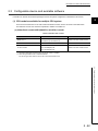
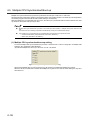
1.3 Difference from Single CPU System
1
Differences between the single CPU system and the multiple CPU system are described in this section.
2
Refer to the manuals below for the single CPU system.
QCPU User's Manual (Hardware Design, Maintenance and Inspection)
User's Manual (Function Explanation, Program Fundamentals) for the CPU module used
3
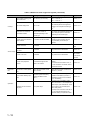
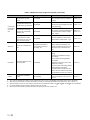
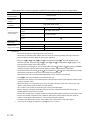
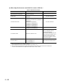
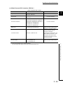
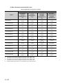
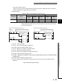
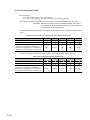
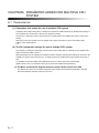
(1) When using the Basic model QCPU
4
Table1.2 Difference from single CPU system
Item
Single CPU system
Multiple CPU system
Maximum number of extension
I/O modules
Main base unit model
25 - (No. of CPUs)*1,*2
24
Extension base unit model
Extension cable type
8
Within 13.2 m
Q6 P, Q6 SP
Q6 RP
-
Function version A or later
Function version B
Function version A or later
Function version B or later
Intelligent function module
Function version A or later
(Function version A or later for QD62,
QD62D and QD62E. No version
restriction for QI60.)
GX Developer
Available
software
package
7
-
Q6 RB
QC05B, QC06B, QC12B, QC30B, QC50B, QC100B
Available
module
2.1.1
Version 7 or later
Version 8 or later
GX Configurator-AD
Version 1.10L or later*3
GX Configurator-DA
Version 1.10L or later*3
GX Configurator-SC
Version 1.10L or later
GX Configurator-CT
Version 1.10L or later*3
GX Configurator-TI
Version 1.10L or later*3
GX Configurator-TC
Version 1.10L or later
GX Configurator-FL
Version 1.10L or later
GX Configurator-QP
Version 2.10L or later
GX Configurator-PT
Version 1.10L or later
GX Configurator-AS
Version 1.13P or later
GX Configurator-MB
Version 1.00A or later
GX Configurator-DN
Version 1.10L or later
Section 2.3
(To the next page)
1 - 11
1.3 Difference from Single CPU System
I/O module
Section
Q5 B, Q6 B
cable
Basic model QCPU
6
-
Q3 RB
Overall distance of extension
Power supply module model
5
Q3 B, Q3 SB, Q3 DB
System configuration
ence
4 stages
stages
Maximum number of mountable
Refer-
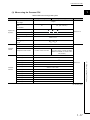
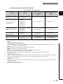
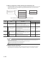
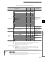
Table1.2 Difference from single CPU system (continued)
Item
CPU module mounting position and CPU No.
Single CPU system
Multiple CPU system
Reference
CPU slot = CPU No. 1
CPU slot only (no CPU No.)
Slot 0 = CPU No. 2
Section 3.1.1
Slot 1 = CPU No. 3
The number assigned to the right of the
Concept
I/O number assignment
Slot 0 is 00H.
CPU module placed in the rightmost
position in the multiple CPU setting is
Section 3.3.1
00H.*4
The number of mountable modRestrictions on number of
ules per CPU module is
mountable modules
restricted depending on the
module type.
The number of mountable modules per
QCPU and per system is restricted
Section 2.4
depending on the module type.
Setting the relations between the CPU
Access from CPU module to
other modules
All modules can be controlled.
module and other modules with the
PLC parameter (control CPU) is
Section 3.4
required.
Access from GOT
Access with instruction using
link direct
Manuals for
Accessible
Accessible
GOT
Only control CPU is accessible.
Access range
Section 3.6
CC-Link sys-
Access to CC-Link
Accessible
Only control CPU is accessible.
tem master/
local module
manuals
Accessible through RS-232 cable or via
Access from peripheral
Accessible through RS-232
devices
cable or via network.
network.
For access when the Motion CPU, or
Section 2.2
PC CPU module is connected, refer to
the relevant manual.
Clock function
Clock data used by intelligent function module (QD75,
etc.)
CPU module resetting operation
Clock data of the Basic model
Clock data of the Basic model QCPU
QCPU is used.
(CPU No. 1) is used.
The entire system is reset by
resetting the Basic model
QCPU.
Section 3.8.2
The entire system is reset by resetting
the Basic model QCPU (CPU No. 1).
( Resetting CPU No. 2 and 3 individu-
Section 3.9
ally is not allowed.)
For a stop error of the Basic model
QCPU of CPU No. 1, the multiple CPU
Operation
system stops. (CPU modules No. 2 and
Operation for CPU module
stop error
The system stops.
3 are in "MULTI CPU DOWN (Error
code: 7000)" status.
Section 3.10
For a stop error occurred in CPU No. 2
or 3, the operation depends on the
parameter setting of "Operation mode".
(To the next page)
1 - 12
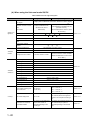
CHAPTER1 OUTLINE
1
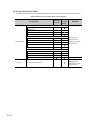
Table1.2 Difference from single CPU system (continued)
Item
Single CPU system
Multiple CPU system
Reference
2
Basic model QCPU = 320 points
Motion CPU = 2048 points
Communication using CPU
shared memory by auto
Not available
refresh
C Controller module = 2048 points
PC CPU module = 2048 points
Section 4.1.2
3
Total points of all CPU modules: 4416
points
Communication between
CPU mod-
Communication using CPU
shared memory by programs
With TO, S.TO and/or FROM instrucNot available
Section 4.1.4
4
CPU: 5 types, Instructions dedicated to
Section 4.2,
the communication between multiple
Section 4.3.1
5
Section 4.3.2
6
tions and instruction using the multiple
CPU area device (U3En\G ).
ules
Instructions dedicated to the Motion
Communication from Basic
model QCPU to Motion CPU
Not available
CPUs: 3 types
Communication from Basic
model QCPU to PC CPU
Not available
module
Communication dedicated instruction
between multiple CPUs: 1 type
In addition to factors for the single CPU
Scan time
Factors for increasing scan
time
Writing data during RUN or
system, refresh processing for CPU
communication processing
modules in Multiple CPU system and
time setting, etc.
waiting time may increase the scan
Section 5.2
time.
7
8
1)No. of CPU modules (Multiple CPU
setting)
2)Control CPU (detailed I/O assignment setting)
Parameter
Parameters added for multiple CPU system
CPU setting)
Not available
4)Operation mode for CPU error stop
Section 6.1
(Multiple CPU setting)
5)Communication area setting (refresh
setting) (Multiple CPU setting)
Some parameters must be set to the
same for all CPU modules while others
may be different for each CPU module.
Caution
*1:
*2:
*3:
*4:
AnS/A series-compatible
module
The AnS/A series-compatible modules cannot be used.
Section 7.1
"No. of CPUs" indicates the number of CPU modules set at "No. of PLC" in the Multiple CPU settings screen of PLC parameter.
When the PC CPU module is mounted, the maximum number of mountable I/O modules is the result of "25 - (No. of CPUs + 1)".
For some intelligent function modules, different version may be used.
When the PC CPU module is mounted, the slot to the right of the PC CPU module is 10H.
1 - 13
1.3 Difference from Single CPU System
3)Out-of-group I/O setting (Multiple
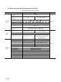
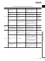
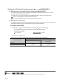
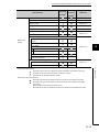
(2) When using the High Performance model QCPU
Table1.3 Difference from single CPU system
Item
Single CPU system
Multiple CPU system
Maximum number of exten-
Reference
7 stages
sion stages
Maximum number of mountable
65 - (No. of CPUs)*1,*2
64
I/O modules
System con-
Main base unit model*3
figuration
Extension base unit model*3
Extension cable type
Q3 B, Q3 SB, Q3 RB, Q3 DB
Q5 B, Q6 B, QA1S6 B, QA6 B, QA6ADP+A5 B/A6 B, Q6 RB
QC05B, QC06B, QC12B, QC30B, QC50B, QC100B
Overall distance of extension
Within 13.2 m
cable
Power supply module
model*3
High Performance model
QCPU
Available
I/O module
Section 2.1.2
Q6 P, Q6 SP, Q6 RP, A1S6 P, A6 P
Function version A or later
Function version B
Function version A or later
Function version B or later
module
Intelligent function module
(Function version A or later for QD62,
Function version A or later
QD62D and QD62E. No function
restriction for QI60.)
GX Developer
Available
software
Version 4 or later
Version 6 or later
GX Configurator-AD
SW0D5C-QADU 00A or later
*4
SW05D5C-QADU 20C or later*4
GX Configurator-DA
SW0D5C-QDAU 00A or later*4
SW05D5C-QDAU 20C or later*4
GX Configurator-SC
SW0D5C-QSCU 00A or later*4
SW05D5C-QSCU 20C or later*4
GX Configurator-CT
SW0D5C-QCTU 00A or later*4
SW05D5C-QCTU 20C or later*4
GX Configurator-TI
Version 1.00A or later
GX Configurator-TC
SW0D5C-QCTU 00A or later
GX Configurator-FL
SW0D5C-QFLU 00A or later
GX Configurator-QP
Version 2.00A or later
GX Configurator-PT
Version 1.00A or later
GX Configurator-AS
Version 1.13P or later
GX Configurator-MB
Version 1.00A or later
GX Configurator-DN
Version 1.00A or later
Section 2.3
(To the next page)
1 - 14
CHAPTER1 OUTLINE
1
Table1.3 Difference from single CPU system (continued)
Item
Single CPU system
Multiple CPU system
Reference
2
CPU slot = CPU No. 1
CPU module mounting position and CPU No.
CPU slot only (no CPU No.)
Slot 0 = CPU No. 2
Slot 1 = CPU No. 3
Section 3.1.2
Slot 2 = CPU No. 4
3
The number assigned to the right of the
Concept
I/O number assignment
Slot 0 is 00H.
CPU module placed in the rightmost
position in the multiple CPU setting is
Section 3.3.1
4
00H.*5
The number of mountable modRestriction on number of
ules per CPU module is
mountable modules
restricted depending on the
module type.
The number of mountable modules per
QCPU and per system is restricted
Section 2.4
depending on the module type.
5
Setting the relations between the CPU
Access from CPU module to
other modules
All modules can be controlled.
module and other modules with the
PLC parameter (control CPU) is
Section 3.4
6
required.
Access from GOT
Access with instruction using
link direct
Accessible
Accessible
Accessible to the High Performance
Manuals for
model QCPU of the specified CPU No.
GOT
Only control CPU is accessible.
Section 3.6
CC-Link sys-
Access range
Access to CC-Link
Accessible
Only control CPU is accessible.
7
8
tem master/
local module
manuals
cable, or via network.
Access from peripheral
Accessible through USB or RS-
For access when the Motion CPU, PC
devices
232 cable, or via network.
CPU module, or C Controller module is
Section 2.2
connected, refer to the manual of each
CPU module.
Clock function
Clock data used by intelligent function module (QD75,
etc.)
CPU module resetting operation
Clock data of the High Perfor-
Clock data of the High Performance
mance model QCPU is used.
model QCPU (CPU No. 1) is used.
The entire system is reset by
resetting the High Performance
model QCPU.
Section 3.8.2
The entire system is reset by resetting
the High Performance model QCPU
(CPU No. 1). (Resetting CPU No. 2 to 4
Section 3.9
individually is not allowed.)
For a stop error of the High Performance model QCPU of CPU No. 1, the
Operation
multiple CPU system stops. (CPU modOperation for CPU module
stop error
ules No. 2 to 4 are in "MULTI CPU
The system stops.
DOWN (Error code: 7000)" status.
Section 3.10
For a stop error occurred in any of CPU
No. 2 to 4, the operation depends on
the parameter setting of "Operation
mode".
(To the next page)
1 - 15
1.3 Difference from Single CPU System
Accessible through USB or RS-232
Table1.3 Difference from single CPU system (continued)
Single CPU system
Communication using CPU
shared memory by auto
Not available
refresh
Communication using CPU
Communication between
CPU modules
shared memory by programs
Reference
CPU. The total for all CPU modules is
Section 4.1.2
8k words.
With S.TO / FROM instructions and
Not available
instruction using the multiple CPU area
Section 4.1.4
device (U3En\G ).
Instructions dedicated to the Motion
Communication from High
Performance model QCPU
Multiple CPU system
Up to 2k words in total of 4 settings per
Not available
to Motion CPU
CPU: 5 types, Instructions dedicated to
Section 4.2,
the communication between multiple
Section 4.3.1
CPUs: 3 types
Communication from the
High Performance model
QCPU to the PC CPU mod-
Not available
Instruction dedicated to the communication between multiple CPUs: 1 type
Section 4.3.2
ule/C Controller module
In addition to factors for the single CPU
Scan time
Factors for increasing scan
time
Writing data during RUN or
system, refresh processing for CPU
communication processing
modules in Multiple CPU system and
time setting, etc.
waiting time may increase the scan
Section 5.2
time.
1)No. of CPU modules (Multiple CPU
setting)
2)Control CPU (detailed I/O assignment setting)
3)Out-of-group I/O setting (Multiple
Parameter
Parameters added for multiple CPU system
CPU setting)
Not available
4)Operation mode for CPU error stop
Section 6.1
(Multiple CPU setting)
5)Communication area setting (refresh
setting) (Multiple CPU setting)
Some parameters must be set to the
same for all CPU modules while others
may be different for each CPU module.
Caution
AnS/A series-compatible
module
Use is allowed when the High PerforUse is allowed.
mance model QCPU is set to the con-
Section 7.1
trol CPU.
*1: "No. of CPUs" indicates the number of CPU modules set at "No. of PLC" in the Multiple CPU settings screen of PLC parameter.
*2: When the PC CPU module is mounted, the maximum number of mountable I/O modules is the result of "65 - (No. of CPUs + 1)".
*3: When the Motion CPU or PC CPU module is mounted on the multiple CPU system, Q3 RB, Q6 RB, and Q6 RP are not available.
*4: For some intelligent function modules, different version may be used.
*5: When the PC CPU module is mounted, the slot to the right of the PC CPU module is 10H.
1 - 16
CHAPTER1 OUTLINE
1
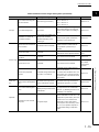
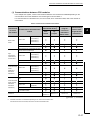
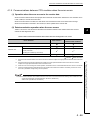
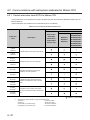
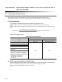
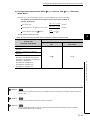
(3) When using the Process CPU
Table1.4 Difference from single CPU system
Item
Single CPU system
Multiple CPU system
Maximum number of exten-
Reference
7 stages
sion stages
3
Maximum number of mountable
2
65 - (No. of CPUs)*1
64
I/O modules
System configuration
Main base unit model*3
Extension base unit model
Q3 B, Q3 RB, Q3 DB
*3
Extension cable type
Q5 B, Q6 B, Q6 RB
QC05B, QC06B, QC12B, QC30B, QC50B, QC100B
Overall distance of extension
model*3
Process CPU
I/O module
Q6 P, Q6 RP
6
No restrictions on function version
Function version A or later
Available
module
7
Function version B or later
Intelligent function module
Function version A or later
(Function version A or later for QD62,
QD62D and QD62E. No version restric-
8
tion for QI60.)
GX Developer
software
Version 7.10L or later
GX Configurator-AD
Version 1.13P or later*4
GX Configurator-DA
Version 1.13P or later*4
GX Configurator-SC
Version 1.13P or later
GX Configurator-CT
Version 1.13P or later*4
GX Configurator-TI
Version 1.13P or later*4
GX Configurator-TC
Version 1.13P or later
GX Configurator-FL
Version 1.13P or later
GX Configurator-QP
Version 2.13P or later
GX Configurator-PT
Version 1.13P or later
GX Configurator-AS
Version 1.13P or later
GX Configurator-MB
Version 1.00A or later
GX Configurator-DN
Version 1.13P or later
Section 2.3
(To the next page)
1 - 17
1.3 Difference from Single CPU System
Available
4
5
Within 13.2 m
cable
Power supply module
Section 2.1.2
.
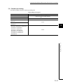
Table1.4 Difference from single CPU system (continued)
Item
Single CPU system
Multiple CPU system
Reference
CPU slot = CPU No. 1
CPU module mounting posi-
CPU slot only
Slot 0 = CPU No. 2
tion and CPU No.
(no CPU No.)
Slot 1 = CPU No. 3
Section 3.1.2
Slot 2 = CPU No. 4
The number assigned to the right of the
Concept
I/O number assignment
Slot 0 is 00H.
CPU module placed in the rightmost
position in the multiple CPU setting is
Section 3.3.1
00H.*5
The number of mountable mod-
The number of mountable modules per
Restrictions on number of
ules per CPU module is
CPU module and per system is
mountable modules
restricted depending on the
restricted depending on the module
module type.
type.
Section 2.4
Setting the relations between the CPU
Access from CPU module to
other modules
All modules can be controlled.
module and other modules with the
PLC parameter (control CPU) is
Section 3.4
required.
Access from GOT
Access with instruction using
link direct
Accessible
Accessible
Accessible to the Process CPU of the
Manuals for
specified CPU No.
GOT
Only control CPU is accessible.
Section 3.6
CC-Link sys-
Access range
Access to CC-Link
Accessible
Only control CPU is accessible.
tem master/
local module
manuals
Accessible through USB or RS-232
cable, or via network.
Access from peripheral
Accessible through USB or RS- For access when the Motion CPU, PC
devices
232 cable, or via network.
CPU module, or C Controller module is
Section 2.2
connected, refer to the manual of each
CPU module.
Clock function
Clock data used by intelligent function module (QD75,
etc.)
Clock data of the Process CPU
Clock data of the Process CPU (CPU
is used.
No. 1) is used.
Section 3.8.2
The entire system is reset by resetting
CPU module resetting oper-
The entire system is reset by
the Process CPU (CPU No. 1).
ation
resetting the Process CPU.
(Resetting CPU No. 2 to 4 individually
Section 3.9
is not allowed.)
For a stop error of the Process CPU of
CPU No. 1, the multiple CPU system
Operation
stops. (CPU modules No. 2 to 4 are in
Operation for CPU module
stop error
"MULTI CPU DOWN (Error code:
The system stops.
7000)" status.
Section 3.10
For a stop error occurred in any of CPU
No. 2 to 4, the operation depends on
the parameter setting of "Operation
mode".
(To the next page)
1 - 18
CHAPTER1 OUTLINE
.
1
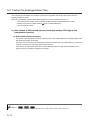
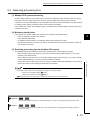
Table1.4 Difference from single CPU system (continued)
Item
Single CPU system
Communication using CPU
shared memory by auto
Not available
refresh
Communication using CPU
Communica-
shared memory by programs
ules
Reference
CPU. The total for all CPU modules is
Section 4.1.2
With TO / FROM instructions and
Not available
Section 4.1.4
3
CPU: 5 types, Instructions dedicated to
Section 4.2,
4
the communication between multiple
Section 4.3.1
instruction using the multiple CPU area
device (U3En\G ).
Instructions dedicated to the Motion
Communication from Process CPU to Motion CPU
2
8k words.
tion between
CPU mod-
Multiple CPU system
Up to 2k words in total of 4 settings per
Not available
CPUs: 3 types
Communication from the
Process CPU to the PC CPU
Not available
module/C Controller module
Communication dedicated instruction
between multiple CPUs: 1 type
Section 4.3.2
In addition to factors for the single CPU
Scan time
Factors for increasing scan
time
Writing data during RUN or
system, refresh processing for CPU
communication processing
modules in Multiple CPU system and
time setting, etc.
waiting time may increase the scan
5
6
Section 5.2
7
time.
1)No. of CPU modules (Multiple CPU
setting)
8
2)Control CPU (detailed I/O assignment setting)
3)Out-of-group I/O setting (Multiple
Parameter
Parameters added for multi-
4)Operation mode for CPU error stop
Section 6.1
(Multiple CPU setting)
5)Communication area setting (auto
refresh setting) (Multiple CPU setting)
Some parameters must be set to the
same for all CPU modules while others
may be different for each CPU module.
Caution
AnS/A series-compatible
module
The AnS/A series-compatible modules cannot be used.
Section 7.1
*1: "No. of CPUs" indicates the number of CPU modules set at "No. of PLC" in the Multiple CPU settings screen of PLC parameter.
*2: When the PC CPU module is mounted, the maximum number of mountable I/O modules is the result of "65 - (No. of CPUs + 1)".
*3: When the Motion CPU or PC CPU module is mounted on the multiple CPU system, Q3 RB, Q6 RB, and Q6 RP are not available.
*4: For some intelligent function modules, different version may be used.
*5: When the PC CPU module is mounted, the slot to the right of the PC CPU module is 10H.
1 - 19
1.3 Difference from Single CPU System
ple CPU system
CPU setting)
Not available
(4) When using the Universal model QCPU
Table1.5 Difference from single CPU system
Item
Single CPU system
Maximum number of extension stages
Multiple CPU system
Reference
7 stages (when the Q00UCPU, Q01UCPU, Q02UCPU is used:4 stages)
65 - (Number of CPUs) *1,*2
Maximum number of mountable
I/O modules
(Use of Q00UCPU and Q01UCPU:25-
Q01UCPU:24, Use of
(Number of CPUs),
Q02CPU:36)
when the Q02UCPU is used:37 - (Number of CPUs))
System configuration
64(Use of Q00UCPU and
Main base unit model
*3
Q3 B, Q3 SB, Q3 RB, Q3 DB
Extension base unit model*3
Extension cable type
Q5 B, Q6 B, Q6 RB
QC05B, QC06B, QC12B, QC30B, QC50B, QC100B
Overall distance of extension
Within 13.2 m
cable
Power supply module
Q6 P, Q6 SP, Q6 RP
model*3
Universal model QCPU
No restrictions on function version
I/O module
Function version A or later
Available
module
Section 2.1.3
Function version B or later
Intelligent function module
Function version A or later
(Function version A or later for QD62,
QD62D and QD62E. No version restriction for QI60.)
Available
software*5
GX Developer
Version 8.48A or later
GX Configurator-AD
Version 2.05F or later
GX Configurator-DA
Version 2.06G or later
GX Configurator-SC
Version 2.12N or later
GX Configurator-CT
Version 1.25B or later
GX Configurator-TI
Version 1.24A or later
GX Configurator-TC
Version 1.23Z or later
GX Configurator-FL
Version 1.23Z or later
GX Configurator-QP
Version 2.25B or later
GX Configurator-PT
Version 1.23Z or later
GX Configurator-AS
Version 1.21X or later
GX Configurator-MB
Version 1.08J or later
GX Configurator-DN
Version 1.23Z or later
Section 2.2
CPU slot = CPU No. 1
CPU module mounting posi-
CPU slot only
Slot 0 = CPU No. 2
tion and CPU No.
(no CPU No.)
Slot 1 = CPU No. 3
Section 3.1.3
Slot 2 = CPU No. 4*4
The number assigned to the right of the
Concept
I/O number assignment
Slot 0 is 00H.
CPU module placed in the rightmost
position in the multiple CPU setting is
Section 3.3.1
00H.
1 - 20
The number of mountable mod-
The number of mountable modules per
Restrictions on number of
ules per CPU module is
CPU module and per system is
mountable modules
restricted depending on the
restricted depending on the module
module type.
type.
Section 2.4
CHAPTER1 OUTLINE
1
Table1.5 Difference from single CPU system (continued)
Item
Single CPU system
Multiple CPU system
Reference
2
Setting the relations between the CPU
Access from CPU module to
other modules
All modules can be controlled.
module and other modules with the
PLC parameter (control CPU) is
Section 3.4
required.
Access from GOT
Access with instruction using
link direct
Accessible
Accessible
Accessible to the Universal model
Manuals for
QCPU of the specified CPU No.
GOT
Only control CPU is accessible.
Section 3.6
3
4
CC-Link sys-
Access range
Access to CC-Link
Accessible
Only control CPU is accessible.
tem master/
local module
manuals
5
Accessible through USB, RS-232 or
Access from peripheral
devices
Accessible through USB, RS232 or Ethernet cables*6, or via
networks.
Ethernet cables*6, or via networks.
For access when the Motion CPU, PC
CPU module, or C Controller module is
Section 2.2
connected, refer to the manual of each
7
CPU module.
Clock data used by CPU
Clock function
modules No.2 to No.4
Clock data used by intelligent function module (QD75,
etc.)
Not available
Clock data of the Universal model
QCPU (CPU No.1) is used.*7
Clock data of the Universal
Clock data of the Universal model
model QCPU is used.
QCPU (CPU No. 1) is used.
6
Section 3.8.1
Section 3.8.2
8
The entire system is reset by resetting
ation
the Universal model QCPU (CPU No.
resetting the Universal model
1).
QCPU.
(Resetting CPU No. 2 to 4 individually
Section 3.9
is not allowed.)
For a stop error of the Universal model
QCPU of CPU No. 1, the multiple CPU
system stops. (CPU modules No. 2 to 4
Operation
Operation for CPU module
stop error
are in "MULTI CPU DOWN (Error code:
The system stops.
7000)" status.
Section 3.10
For a stop error occurred in any of CPU
No. 2 to 4, the operation depends on
the parameter setting of "Operation
mode".
It is possible to choose whether to syn-
Multiple CPU system synchronized boot-up
chronize the boot-up of CPU modules
Not available
in the Multiple CPU system or not. (The
Section 4.5
default synchronizes the boot-up of all
CPU modules.)
1 - 21
1.3 Difference from Single CPU System
CPU module resetting oper-
The entire system is reset by
Table1.5 Difference from single CPU system (continued)
Item
Single CPU system
Not available
refresh
mission area by auto
tion between
gram
Using two CPU modules: 14k words
Section 4.1.3
Using three CPU modules: 13k words
Using four CPU modules: 12k words
Perform communication with the TO
Not available
instruction, FROM instruction, and/or
an instruction using the multiple CPU
Section 4.1.4
shared device (U3En\G ).
CPU modules
Section 4.1.2
CPU modules is as shown below.
Not available
Communication using CPU
shared memory by a pro-
The total for all CPU modules is 8k
A memory size that can be used for all
refresh*8
Communica-
is up to 2k words in total of four ranges.
words.
Communication using multiple CPU high speed trans-
Reference
Transmission from each CPU module
Communication using QCPU
standard area by auto
Multiple CPU system
Communication is available with the folCommunication from Universal model QCPU to Motion
lowing:
Not available
CPU
Motion dedicated instruction: 5 types
Multiple CPU high-speed transmission
Section 4.2,
Section 4.3.1
dedicated instruction: 3 types
Communication from the
Universal model QCPU to
the PC CPU module/C Con-
Perform communication with the multiNot available
Section 4.3.2
instruction: 1 type.
troller module
Communication from the
Universal model QCPU to
ple CPU transmission dedicated
Perform communication with the multiNot available
the Universal model QCPU
ple CPU high-speed transmission dedi-
Section 4.3.3
cated instruction: 2 types.
In addition to factors for the single CPU
Scan time
Factors for increasing scan
time
Writing data during RUN or
system, refresh processing for CPU
communication processing
modules in Multiple CPU system and
time setting, etc.
waiting time may increase the scan
Section 5.2
time.
1)No. of CPU modules (Multiple CPU
setting)
2)Control CPU (detailed I/O assignment setting)
3)Out-of-group I/O setting (Multiple
CPU setting)
4)Operation mode for CPU error stop
(Multiple CPU setting)
Parameter
Parameters added for multiple CPU system
Not available
5)Multiple CPU synchronized boot-up
(Multiple CPU settings)
Section 6.1
6)Multiple CPU high speed transmission area setting (Multiple CPU settings)*9
7)Communication area setting(refresh
setting)
Some parameters must be set to the
same for all CPU modules while others
may be different for each CPU module.
Caution
1 - 22
AnS/A series-compatible
module
The AnS/A series-compatible modules cannot be used.
Section 7.1
CHAPTER1 OUTLINE
*1: "No. of CPUs" indicates the number of CPU modules set at "No. of PLC" in the Multiple CPU settings screen of PLC parameter.
*2: When the PC CPU module is mounted, the maximum number of mountable I/O modules is the result of "65 - (Number of CPUs + 1)
(when using the Q00UCPU, Q01UCPU: 24 - (Number of CPUs + 1)) (when using the Q02UCPU: 37 - (Number of CPUs + 1))".
*3: When the Motion CPU or PC CPU module is mounted on the multiple CPU system, Q3 RB, Q6 RB, and Q6 RP are not available.
*4: When the Q00UCPU, Q01UCPU, Q02UCPU is used as the CPU module 1, up to three CPU modules can be mounted.
Therefore, the CPU No. 4 does not exist.
*5: These versions can be used for the Q02UCPU, Q03UDCPU, Q04UDHCPU, and Q06UDHCPU. For software versions available for a
Universal model QCPU other than the above, refer to Section 2.3.
*6: Available for Built-in Ethernet port QCPUs only.
*7: When a Universal model QCPU (except Q00UCPU, Q01UCPU, Q02UCPU) or Motion CPU (Q172DCPU or Q173DCPU) is used as any
of CPUs No.2 to No.4, clock data in CPU No.1 can be used.
*8: When CPU No.1 is the Q00UCPU, Q01UCPU, Q02UCPU, the communication by the auto refresh using the multiple CPU high speed
transmission area is not available.
*9: When CPU No.1 is the Q02UCPU, the multiple CPU high speed transmission area cannot be set up.
1
2
3
4
5
6
7
8
1.3 Difference from Single CPU System
1 - 23
CHAPTER2 SYSTEM CONFIGURATION
This chapter explains the system configuration of Multiple CPU Systems, and the precautions for Multiple CPU System
configuration.
2.1 System configuration
2.1.1 System configuration using Basic model QCPU (Q00CPU, Q01CPU)
This following explains the system configuration using the Basic model QCPU.
(1) System using the main base unit (Q3 B)
(a) System configuration
Battery for
QCPU (Q6BAT)
Basic model
QCPU
Motion
CPU*3
PC CPU
module *3,*4,*6
Q3
B type main base unit *1
Extension cable
Q series power supply/input/output/intelligent
function module/motion module *5
Q5
Q6
*1:
*2:
*3:
*4:
*5:
*6:
2-1
C Controller
module *6
B type extension base unit *2
B type extension base unit *1
As a power supply module, use the Q series power supply module.
Make the power consumption within the rated output current value of the power supply module.
The Slim type power supply module and Redundant power supply module cannot be used as a power supply module.
No Q series power supply module is required for the Q5 B type extension base unit.
The QCPU battery (Q6BAT) cannot be installed to the Motion CPU and the PC CPU module.
For further information on PC CPU module, consult CONTEC Co., Ltd
Tel: +81-6-6472-7130
Be sure to set the control CPU of motion modules to the Motion CPU
The PC CPU module and C Controller module cannot be mounted together.
Figure 2.1 System configuration when Basic model QCPU is used
CHAPTER2 SYSTEM CONFIGURATION
1
When the multiple CPU system is configured using the Basic model QCPU as the CPU No.1, only the following CPU
modules can be used as the CPUs No.2 and 3.
• Motion CPU(Q172CPUN(-T), Q173CPUN(-T), Q172HCPU(-T), Q173HCPU(-T))
• PC CPU module
• C Controller module
Note that the PC CPU module and C Controller module cannot be mounted together.
2
3
4
5
6
7
8
2.1 System configuration
2.1.1 System configuration using Basic model QCPU (Q00CPU, Q01CPU)
2-2
(b) Outline of system configuration
Main base unit.........32-point modules are mounted on each slot.
3
4
5
6
7
70 to 8F
2
90 to AF
1
50 to 6F
0
30 to 4F
CPU
10 to 2F
Q38B (8 slots occupied)
...... Slot number
...... I/O number
Empty space of 16 points
CPU module 3 *1
CPU module 2
CPU module 1
Q series power
supply module
Extension base unit .........32-point modules are mounted on each slot.
10
14
15
16
17
170 to 18F
1B0 to 1CF
1D0 to 1EF
150 to 16F
13
190 to 1AF
Q55B (5 slots occupied)
11
12
110 to 12F
D0 to EF
9
F0 to 10F
B0 to CF
8
130 to 14F
Q65B (5 slots occupied)
2nd
extension
Q65B (5 slots occupied)
250 to 26F
270 to 28F
23
24
25
26
27
Inhibited.
22
Inhibited.
230 to 24F
21
Inhibited.
210 to 22F
20
Inhibited.
19
290 to 2AF
1F0 to 20F
18
1st
extension
Q65B (5 slots occupied)
3rd
extension
4th
extension
Error in mounting
*1:
2-3
Shows when the CPU module 3 is the PC CPU module.
If the CPU module 3 is the C Controller module, a module can be mounted on the slot 2.
Figure 2.2 System configuration example for using Basic model QCPU
CHAPTER2 SYSTEM CONFIGURATION
Table2.1 Restrictions on system configuration, available base units, extension cables, and power supply modules
1
CPU1: CPU No. 1 (Basic model QCPU), CPU2: CPU No. 2 (Motion CPU),
CPU number
CPU3: CPU No.3 (PC CPU module/C Controller module)
Maximum number of
4 extension units
extension stages
2
Maximum number of
mountable I/O
25 - (No. of CPUs)
3
modules
Available main base
Q33B, Q35B, Q38B, Q312B
unit model
Available extension
base unit model
Model not requiring power supply module
Model requiring Q series power supply
module
Available extension
cable model
Available power
supply module model
Q52B, Q55B
4
Q63B, Q65B, Q68B, Q612B
5
QC05B, QC06B, QC12B, QC30B, QC50B, QC100B
Q61P-A1, Q61P-A2, Q61P, Q61P-D, Q62P, Q63P, Q64P, Q64PN
6
Precautions
• Do not use an extension cable longer than 13.2m (43.31 ft).
• When using an extension cable, keep it away from the main circuit (high voltage and large current) line.
• Set the number of extension stages so as not to be duplicated.
7
• The QA1S6 B, QA6 B, QA6ADP+A5 B/A6 B, or Q6R B cannot be connected as an extension base
unit.
• Although there is no restriction on the connection order of the Q5 B and the Q6 B, check the availability of
8
them by referring to QCPU User's Manual (Hardware Design, Maintenance and Inspection) when both the
Q5 B and the Q6 B exist as the extension base unit.
unit by an extension cable.
• When 26 modules or more are mounted, an error "SP. UNIT LAY ERR." (error code: 2124) occurs. (The
number of mountable modules includes one CPU module.)
• The redundant base unit cannot be used when the Basic model QCPU is mounted on the multiple CPU
system.
• "No. of CPUs" is the number of CPUs set by [No. of PLC] of GX Developer.
• The PC CPU module occupies two slots. Therefore, when the PC CPU module is used, the maximum
number of I/O modules is decreased by 1 from the value indicated in Table2.1.
• The PC CPU module and C Controller module cannot be mounted together: therefore; mount either of them.
• For details of the Motion CPU, PC CPU module, and C Controller module, refer to the manuals of each CPU
module.
2-4
2.1 System configuration
2.1.1 System configuration using Basic model QCPU (Q00CPU, Q01CPU)
• Connect the OUT connector of an extension base unit and the IN connector of the adjacent extension base
(2) When using the slim type main base unit (Q3 SB)
(a) System configuration
Battery for
QCPU (Q6BAT)
Basic model
QCPU
C Controller
module
Slim type main base unit *1, *2
Slim type power supply/input/output/intelligent
function module
*1:
*2:
The slim type main base unit does not have an extension cable connector.
The extension base unit and GOT cannot be bus-connected.
As a power supply module, use the slim type power supply module.
Keep the current consumption within the rated output current of the power supply module.
The Q series power supply module and the redundant power supply module are not available for the power supply
module.
Figure 2.3 System configuration when Q3
SB is used
When the multiple CPU system is configured using the Basic model QCPU as the CPU No.1, only the C Controller module
can be used as the CPU No.2.
2-5
CHAPTER2 SYSTEM CONFIGURATION
(b) Outline of system configuration
1
Slim type
power supply
module
2
3
4
60 to 7F
PULL
1
40 to 5F
0
20 to 3F
CPU
00 to 1F
Slim type main base unit
32-point modules are mounted on each slot.
Q35SB (5 slots occupied)
2
Slot number
3
I/O number
4
CPU module 2
CPU module 1
Figure 2.4 System configuration example for using Q3
SB
5
Table2.2 Restrictions on system configuration, available base units, extension cables, and power supply modules
CPU number
CPU1: CPU No. 1 (Basic model QCPU), CPU2: CPU No. 2 (C Controller module)
Maximum number of
6
Extension not allowed
extension stages
Maximum number of
Q32SB
1
mountable I/O
Q33SB
2
modules
Q35SB
4
Available main base
unit model
Available power
supply module model
7
Q32SB, Q33SB, Q35SB
8
Q61SP
Precautions
2.1 System configuration
2.1.1 System configuration using Basic model QCPU (Q00CPU, Q01CPU)
• The slim type main base unit has no extension cable connector.
The extension base unit and GOT cannot be bus-connected.
2-6
(3) When using the Multiple CPU High speed main base unit (Q3 DB)
(a) System configuration
Battery for
QCPU (Q6BAT)
PC CPU
module *3,*4,*5
Basic model
QCPU
C Controller
module *5
Q3 DB type multiple CPU high speed main
base unit *1
Extension cable
Q series power supply/input/output/intelligent
function module
Q5
Q6
*1:
*2:
*3:
*4:
*5:
B type extension base unit *2
B type extension base unit *1
As a power supply module, use the Q series power supply module.
Make the power consumption within the rated output current value of the power supply module.
The Slim type power supply module and Redundant power supply module cannot be used as a power supply module.
No Q series power supply module is required for the Q5 B type extension base unit.
The QCPU battery (Q6BAT) cannot be installed to the PC CPU module.
For further information on PC CPU module, consult CONTEC Co., Ltd
Tel: +81-6-6472-7130
The PC CPU module and C Controller module cannot be mounted together.
Figure 2.5 System configuration when Basic model QCPU is used
When the multiple CPU system is configured using the Basic model QCPU as the CPU No.1, only the following CPU
modules can be used as the CPUs No.2.
• PC CPU module
• C Controller module
Note that the PC CPU module and C Controller module cannot be mounted together.
2-7
CHAPTER2 SYSTEM CONFIGURATION
(b) Outline of system configuration
1
Main base unit.........32-point modules are mounted on each slot.
Q series power
supply module
4
5
6
7
B0 to CF
3
70 to 8F
2
90 to AF
1
50 to 6F
0
30 to 4F
CPU
10 to 2F
Q38DB (8 slots occupied)
2
...... Slot number
3
...... I/O number
4
Empty space of 16 points
CPU module 2 *1
CPU module 1
Extension base unit .........32-point modules are mounted on each slot.
11
12
150 to 16F
D0 to EF
10
110 to 12F
9
130 to 14F
8
F0 to 10F
Q65B (5 slots occupied)
13
14
15
16
17
170 to 18F
190 to 1AF
1B0 to 1CF
1D0 to 1EF
1F0 to 20F
Q55B (5 slots occupied)
270 to 28F
290 to 2AF
27
Inhibited.
250 to 26F
26
230 to 24F
25
210 to 22F
24
Q65B (5 slots occupied)
3rd
extension
2.1 System configuration
2.1.1 System configuration using Basic model QCPU (Q00CPU, Q01CPU)
23
Inhibited.
22
Inhibited.
21
Inhibited.
20
7
8
2B0 to 2CF
19
6
2nd
extension
Q65B (5 slots occupied)
18
5
1st
extension
4th
extension
Error in mounting
*1:
Shows when the CPU module 2 is the PC CPU module.
If the CPU module 2 is the C Controller module, a module can be mounted on the slot 1.
Figure 2.6 System configuration example for using Basic model QCPU
2-8
Table2.3 Restrictions on system configuration, available base units, extension cables, and power supply modules
CPU number
CPU1: CPU No. 1 (Basic model QCPU), CPU2: CPU No. 2 (PC CPU module C Controller module)
Maximum number of
4 extension units
extension stages
Maximum number of
mountable I/O
25 - (No. of CPUs)
modules
Available main base
Q38DB, Q312DB
unit model
Available extension
base unit model
Model not requiring power supply module
Model requiring Q series power supply
module
Available extension
cable model
Available power
supply module model
Q52B, Q55B
Q63B, Q65B, Q68B, Q612B
QC05B, QC06B, QC12B, QC30B, QC50B, QC100B
Q61P-A1, Q61P-A2, Q61P, Q61P-D, Q62P, Q63P, Q64P, Q64PN
Precautions
• Do not use an extension cable longer than 13.2m (43.31 ft).
• When using an extension cable, keep it away from the main circuit (high voltage and large current) line.
• Set the number of extension stages so as not to be duplicated.
• The QA1S6 B, QA6 B, QA6ADP+A5 B/A6 B, or Q6R B cannot be connected as an extension base
unit.
• Although there is no restriction on the connection order of the Q5 B and the Q6 B, check the availability of
them by referring to QCPU User's Manual (Hardware Design, Maintenance and Inspection) when both the
Q5 B and the Q6 B exist as the extension base unit.
• Connect the OUT connector of an extension base unit and the IN connector of the adjacent extension base
unit by an extension cable.
• When 26 modules or more are mounted, an error "SP. UNIT LAY ERR." (error code: 2124) occurs. (The
number of mountable modules includes one CPU module.)
• The redundant base unit cannot be used when the Basic model QCPU is mounted on the multiple CPU
system.
• "No. of CPUs" is the number of CPUs set by [No. of PLC] of GX Developer.
• The PC CPU module occupies two slots. Therefore, when the PC CPU module is used, the maximum
number of I/O modules is decreased by 1 from the value indicated in Table2.3.
• The PC CPU module and C Controller module cannot be mounted together: therefore; mount either of them.
For details of the Motion CPU, PC CPU module, and C Controller module, refer to the manuals of each CPU
module.
2-9
CHAPTER2 SYSTEM CONFIGURATION
2.1.2 System configuration using High Performance model QCPU or Process
CPU as CPU No.1
This following explains the system configuration using the High Performance model QCPU and the Process CPU
as the CPU No.1.
(1) When using the main base unit (Q3 B)
1
2
3
(a) System configuration
4
5
Memory card *1
6
High Performance
model QCPU
Process CPU
Universal model
QCPU*9,*10
Battery for QCPU (Q6BAT)
Q7BAT-SET
Battery holder
Motion
CPU*5,*11
PC CPU
module *5,*6,*8
C Controller
module *5,*6
7
8
Battery for QCPU (Q7BAT)
Q8BAT-SET *
B type main base unit *2
Battery for QCPU (Q8BAT)
Q series power supply/input/output
/intelligent function module/motion module *7
Extension cable
Q5
Q6
B type extension base unit *4
B type extension base unit *2
QA1S6 B type
extension base unit *3
QA6
B type extension base unit *3,*12
AnS series power supply/input/output/
special function module
A series power supply/input/output/
special function module
Figure 2.7 System configuration when Q3 B is used
2 - 10
2.1 System configuration
2.1.2 System configuration using High Performance model QCPU or Process CPU as CPU No.1
Q8BAT connection cable
Q3
11
*1:
*2:
*3:
Only one memory card can be mounted. Select an appropriate memory card from the SRAM, Flash and ATA in
accordance with application and capacity.
When a commercial memory card is used, the operation is not guaranteed.
Use the Q series power supply module for the power supply module. Keep the current consumption within the rated
output current of the power supply module. The Slim power supply module and Redundant power supply module are not
available for the power supply module.
Use of the Process CPU or the Universal model QCPU in combination with the AnS/A series compatible power supply
module, the I/O module and the special function module is not allowed.
(
Refer to Section 7.1)
The Q Series power supply module is not required for the Q5 B extension base unit.
The motion CPU and PC CPU module do not accept battery for QCPU and memory card.
For further information on PC CPU module, consult CONTEC Co., Ltd Tel: +81-6-6472-7130
Be sure to set the control CPU of the motion module to the Motion CPU.
The PC CPU module and C Controller module cannot be mounted together.
When mounting the Universal model QCPU and the PC CPU module at the same time, use the PPC-CPU852 (MS)-512
as the PC CPU module.
*10: The Q00UCPU, Q01UCPU, Q02UCPU cannot be mounted.
The Universal model QCPU (except Q00UCPU, Q01UCPU, Q02UCPU) and the Motion CPU (Q172CPUN(-T),
Q173CPUN(-T), Q172HCPU(-T), and Q173HCPU(-T)) cannot be mounted at the same time.
*11: When the Q8BAT is used for the Universal model QCPU, use the connection cable whose connector part displays "A".
For details of connector part of a connection cable, refer to the following manual.
*4:
*5:
*6:
*7:
*8:
*9:
QCPU User's Manual (Hardware Design, Maintenance and Inspection)
*12: The QA6ADP+A5 B/A6 B is available. However, when using the QA1S6 B, the QA6ADP+A5 B/A6 B cannot be
connected.
When the multiple CPU system is configured using the High Performance model QCPU or the Process CPU as the CPU
No.1, only the following CPU modules can be used as the CPUs No.2 to No.4.
• High Performance model QCPU
• Process CPU
• Universal model QCPU (except Q00UCPU, Q01UCPU, Q02UCPU)
• Motion CPU(Q172CPUN(-T),Q173CPUN(-T),Q172HCPU(-T),Q173HCPU(-T))
• PC CPU module
• C Controller module
Note that the multiple CPU system cannot be configured using the following combinations.
• Combination of the Universal model QCPU (except Q00UCPU, Q01UCPU, Q02UCPU) and the Motion CPU
(Q172CPUN(-T), Q173CPUN(-T), Q172HCPU(-T), Q173HCPU(-T))
• Combination of the Universal model QCPU (except Q00UCPU, Q01UCPU, Q02UCPU) and the PC CPU module
(PPC-CPU686(MS)-64, PPC-CPU686(MS)-128)
• Combination of the PC CPU module and the C Controller module
2 - 11
CHAPTER2 SYSTEM CONFIGURATION
(b) Outline of system configuration
1
Main base unit.........32-point modules are mounted on each slot.
Q series power
supply module
7
8
9
10
11
100 to 11F
6
E0 to FF
5
C0 to DF
4
80 to 9F
3
A0 to BF
2
60 to 7F
1
40 to 5F
0
20 to 3F
CPU
00 to 1F
Q312B (12 slots occupied)
2
...... Slot number
3
...... I/O number
CPU module 4
CPU module 3
CPU module 2
CPU module 1
4
Extension base unit .........32-point modules are mounted on each slot.
220 to 23F
240 to 25F
260 to 27F
280 to 29F
5A0 to 5BF
5C0 to 5DF
5E0 to 5FF
600 to 61F
620 to 63F
580 to 59F
52
8
AnS series power supply module
QA1S65B (5 slots occupied)
53
54
55
56
57
60
61
62
6th
extension
QA68B (8 slots occupied)
58
59
63
A series power supply
module
inhibited
7th
extension
inhibited
520 to 53F
500 to 51F
4E0 to 4FF
4C0 to 4DF
4th
extension
51
780 to 79E
44
50
6C0 to 6DF
43
49
760 to 77E
42
7
5th
extension
48
6A0 to 6BF
41
4A0 to 4BF
39
480 to 49F
38
460 to 47F
440 to 45F
37
47
740 to 75E
40
Q68B (8 slots occupied)
46
680 to 69F
36
420 to 43F
35
400 to 41F
34
3E0 to 3FF
33
3C0 to 3DF
32
3A0 to 3BF
380 to 39F
360 to 37F
31
3rd
extension
45
2.1 System configuration
2.1.2 System configuration using High Performance model QCPU or Process CPU as CPU No.1
340 to 35F
30
6
QA1S68B (8 slots occupied)
2nd
extension
Q68B (8 slots occupied)
29
5
1st
extension
720 to 73E
320 to 33F
23
560 to 57F
300 to 31F
22
660 to 67F
2E0 to 2FF
21
700 to 71F
2A0 to 2BF
20
540 to 55F
28
19
640 to 65F
27
18
6E0 to 6FF
26
17
200 to 21F
160 to 17F
25
16
1E0 to 1FF
140 to 15F
24
2C0 to 2DF
Q55B (5 slots occupied)
15
1C0 to 1DF
14
180 to 19F
13
1A0 to 1BF
12
120 to 13F
Q612B (12 slots occupied)
Error in
mounting
Figure 2.8 System configuration example for using Q3 B
2 - 12
Table2.4 Restrictions on system configuration, available base units, extension cables, and power supply modules
CPU number
CPU module1: CPU No.1, CPU module 2: CPU No.2, CPU module 3: CPU No.3, CPU module 4: CPU No.4
Maximum number of
7 extension stages
extension stages
Maximum number of
mountable I/O
65 - (No. of CPUs)
modules
Available main base
Q33B, Q35B, Q38B, Q312B
unit model
Type not requiring power supply module
Type requiring Q series power supply
Available extension
base unit model
module
Type requiring AnS series power supply
module
Type requiring A series power supply
module
Available extension
supply module model
Q63B, Q65B, Q68B, Q612B
QA1S65B, QA1S68B
QA65B, QA68B, QA6ADP+A6 B
QC05B, QC06B, QC12B, QC30B, QC50B, QC100B
cable model
Available power
Q52B, Q55B, QA6ADP+A5 B
Q series power supply module
Q61P-A1, Q61P-A2, Q61P, Q61P-D, Q62P, Q63P, Q64P, Q64PN
AnS series power supply module
A1S61PN, A1S62PN, A1S63P
A series power supply module
A61P, A61PN, A62P, A63P, A61PEU, A62PEU
Precautions
• Do not use an extension cable longer than 13.2m (43.31 ft).
• When using an extension cable, keep it away from the main circuit (high voltage and large current) line.
• Set the number of extension stages so as not to be duplicated.
• When the Q5 B, Q6 B, QA1S6 B, QA6 B, and QA6ADP+A5B/A6 B*1 are used together as the
extension base unit, mount the Q5 B/Q6 B, QA1S6 B, QA6 B, and QA6ADP+A5 B/A6 B in order
from the nearest position of the main base unit.
Although there is no restriction on the connection order of the Q5 B and the Q6 RB, check the availability
of them by referring to QCPU User's Manual (Hardware Design, Maintenance and Inspection).
• The extension base units QA1S6 B, QA6 B, and QA6ADP+A5 B/A6 B can be extended when the High
Performance model QCPU is set as the control CPU of the AnS/A series.
When the Process CPU or the Universal model QCPU is used, extension is not allowed.
• The Q6 RB cannot be connected as an extension base unit.
• Connect the OUT connector of an extension base unit and the IN connector of the adjacent extension base
unit by an extension cable.
• When 66 modules or more are mounted, an error "SP. UNIT LAY ERR." (error code: 2124) occurs. (The
number of mountable modules includes one CPU module.)
• "No. of CPUs" is the number of CPUs set by [No. of PLC] of GX Developer.
• When mounting the Universal model QCPU and the PC CPU module at the same time, use the PPCCPU852 (MS)-512 as the PC CPU module.
• The PC CPU module and C Controller module cannot be mounted together: therefore; mount either of them.
• The PC CPU module occupies two slots. Therefore, when the PC CPU module is used, the maximum
number of I/O modules is decreased by 1 from the value indicated in Table2.4.
• For details of the Motion CPU, and PC CPU module, refer to the manual of each CPU module.
*1:
2 - 13
When using the QA1S6 B, the QA6ADP+A5 B/A6 B cannot be connected.
CHAPTER2 SYSTEM CONFIGURATION
1
(2) When using the redundant power main base unit (Q3 RB)
(a) System configuration
2
3
Memory card *1
4
High Performance
model QCPU
Process CPU
Universal model
QCPU
Battery for QCPU (Q6BAT)
Q7BAT-SET
5
6
Q3 RB type redundant
power main base unit *2
Battery holder
7
Battery for QCPU (Q7BAT)
Q8BAT-SET *4
8
Q8BAT connection cable
Battery for QCPU (Q8BAT)
Q5 B type extension base unit *3
Q6 RB type redundant power
extension base unit *2
*1:
*2:
*3:
*4:
Only one memory card can be mounted. Select an appropriate memory card from the SRAM, Flash and ATA in
accordance with application and capacity.
When a commercial memory card is used, the operation is not guaranteed.
Use the redundant power supply module for the power supply module.
The redundant power supply modules Q63RP and Q64RP can be used on one redundant power supply base unit at the
same time.
The Q series power supply module and the slim type power supply module are not available for the power supply
module.
The Q Series power supply module is not required for the Q5 B extension base unit.
When the Q8BAT is used for the Universal model QCPU, use the connection cable whose connector part displays "A".
For details of connector part of a connection cable, refer to the following manual.
QCPU User's Manual (Hardware Design, Maintenance and Inspection)
Figure 2.9 System configuration when Q RB is used
2 - 14
2.1 System configuration
2.1.2 System configuration using High Performance model QCPU or Process CPU as CPU No.1
Redundant power supply/input/output/
intelligent function module
Extension cable
2 - 15
●
When the multiple CPU system is configured using the High Performance model QCPU or the Process CPU as the
CPU No.1, only the following modules can be used as the CPUs No.2 to CPU No.4.
• High Performance model QCPU
• Process CPU
• Universal model QCPU (except Q00UCPU, Q01UCPU, Q02UCPU)
●
When duplicating power supply, use the redundant power supply base unit and the redundant power supply module.
For the power supply module mounted on the redundant power supply base unit, only the redundant power supply
module can be used.
CHAPTER2 SYSTEM CONFIGURATION
(b) Outline of system configuration
1
Redundant main base unit .........32-point module is mounted on each slot.
2
3
4
5
6
7
80 to 9F
2
60 to 7F
1
40 to 5F
0
20 to 3F
CPU
00 to 1F
Q38RB (8 slots occupied)
...... Slot number
3
...... I/O number
4
CPU module 4
CPU module 3
CPU module 2
CPU module 1
Redundant Power
supply module
Extension base unit .........32-point modules are mounted on each slot.
Q55B
(5 slots occupied)
9
10 11 12
6
A0 to BF
C0 to DF
E0 to FF
100 to 11F
120 to 13F
8
5
1st
extension
Q68RB (8 slots occupied)
13 14 15 16 17 18 19 20
37 38 39 40 41 42 43 44
440 to 45F
460 to 47F
480 to 49F
4A0 to 4BF
4C0 to 4DF
4E0 to 4FF
500 to 51F
520 to 53F
2nd
extension
140 to 15F
160 to 17F
180 to 19F
1A0 to 1BF
1C0 to 1DF
1E0 to 1FF
200 to 21F
220 to 23F
Q68RB (8 slots occupied)
Q68RB (8 slots occupied)
3rd
extension
6th
extension
240 to 25F
260 to 27F
280 to 29F
2A0 to 2BF
2C0 to 2DF
2E0 to 2FF
300 to 31F
320 to 33F
540 to 55F
560 to 57F
580 to 59F
5A0 to 5BF
5C0 to 5DF
5E0 to 5FF
600 to 61F
620 to 63F
45 46 47 48 49 50 51 52
Q68RB (8 slots occupied)
29 30 31 32 33 34 35 36
53 54 55 56 57 58 59 60
640 to 65F
660 to 67F
680 to 69F
6A0 to 6BF
6C0 to 6DF
6E0 to 6FF
700 to 71F
720 to 73F
4th
extension
340 to 35F
360 to 37F
380 to 39F
3A0 to 3BF
3C0 to 3DF
3E0 to 3FF
400 to 41F
420 to 43F
Q68RB (8 slots occupied)
8
2.1 System configuration
2.1.2 System configuration using High Performance model QCPU or Process CPU as CPU No.1
21 22 23 24 25 26 27 28
Q68RB (8 slots occupied)
7
5th
extension
7th
extension
Figure 2.10 System configuration example for using Q3 RB
2 - 16
Table2.5 Restrictions on system configuration, available base units, extension cables, and power supply modules
CPU number
CPU module1: CPU No.1, CPU module 2: CPU No.2, CPU module 3: CPU No.3, CPU module 4: CPU No.4
Maximum number of
7 extension stages
extension stages
Maximum number of
65 - (No. of CPUs)
mounted I/O modules
Available main base
Q38RB
unit model
Available extension
base unit model
Type not requiring power supply module
Type requiring redundant power supply
module
Available extension
cable model
Available power
supply module model
Q52B, Q55B
Q68RB
QC05B, QC06B, QC12B, QC30B, QC50B, QC100B
Q63RP, Q64RP
Precautions
• Do not use an extension cable longer than 13.2m (43.31 ft).
• When using an extension cable, keep it away from the main circuit (high voltage and large current) line.
• Set the number of extension stages so as not to be duplicated.
• Although there is no restriction on the connection order of the Q5 B and the Q6R B, check the availability
of them by referring to QCPU User's Manual (Hardware Design, Maintenance and Inspection).
• The Q6 B, QA1S6 B, QA6 B, or QA6ADP+A5 B/A6 B cannot be connected as an extension base
unit.
• Connect the OUT connector of an extension base unit and the IN connector of the adjacent extension base
unit by an extension cable.
• When 66 modules or more are mounted, an error "SP. UNIT LAY ERR." (error code: 2124) occurs. (The
number of mountable modules includes one CPU module.)
• "No. of CPUs" is the number of CPUs set by [No. of PLC] of GX Developer.
• When the redundant base unit is used, bus connection is not available for the GOT.
• When the redundant power main base unit is used, the Motion CPU, and PC CPU module cannot be used.
• When the redundant power main base unit is used, the Motion CPU, PC CPU module, and C Controller
module cannot be used.
2 - 17
CHAPTER2 SYSTEM CONFIGURATION
1
(3) When using the slim type main base unit (Q3 SB)
(a) System configuration
2
3
Memory card *1
4
High Performance
model QCPU
Universal model
QCPU *4
Battery for QCPU (Q6BAT)
Q7BAT-SET
C Controller
module *4,*5
5
6
Slim type main base unit *2,*3
Battery holder
Battery for QCPU (Q7BAT)
Q8BAT-SET *4
7
8
Q8BAT connection cable
*1:
*3:
*4:
*5:
Slim type power supply/input/output/
intelligent function module
One memory card is installed. Select an appropriate memory card from the SRAM, Flash and ATA cards according to the
application and capacity.
When the memory card is used, operation is not guaranteed.
The slim type main base unit does not have an extension cable connector.
The extension base unit and GOT cannot be bus-connected.
As a power supply module, use the slim type power supply module.
Keep the current consumption within the rated output current of the power supply module.
The Q series power supply module and the redundant power supply module are not available for the power supply
module.
When the Q8BAT is used for the Universal model QCPU, use the connection cable whose connector part displays "A".
For details of connector part of a connection cable, refer to the following manual.
QCPU User's Manual (Hardware Design, Maintenance and Inspection)
For memory cards that can be used with the C Controller module, refer to the manual of the C Controller module.
Figure 2.11 System configuration when Q3 SB is used
When the multiple CPU system is configured using the High Performance model QCPU as the CPU No.1, only the following
CPU modules can be used as the CPUs No.2 and 3.
• High Performance model QCPU
• Universal model QCPU (except Q00UCPU, Q01UCPU, Q02UCPU)
• C Controller module
2 - 18
2.1 System configuration
2.1.2 System configuration using High Performance model QCPU or Process CPU as CPU No.1
*2:
Battery for QCPU (Q8BAT)
(b) Outline of system configuration
Slim type main base unit .........32-point module is mounted on each slot.
Slim type power
supply module
1
2
3
4
40 to 5F
0
20 to 3F
CPU
00 to 1F
Q35SB(5 slots occupied)
...... Slot number
...... I/O number
CPU module 3
CPU module 2
CPU module 1
Figure 2.12 System configuration example for using Q3 SB
Table2.6 Restrictions on system configuration, available base units, extension cables, and power supply modules
CPU number
CPU module 1: CPU No.1, CPU module 2: CPU No.2, CPU module 3: CPU No.3
Maximum number of
Extension not allowed
extension stages
Maximum number of
Q32SB
3 - (No. of CPUs)
mountable I/O
Q33SB
4 - (No. of CPUs)
modules
Q35SB
6 - (No. of CPUs)
Available main base
unit model
Available power
supply module model
Q32SB, Q33SB, Q35SB
Q61SP
Precautions
• The slim type main base unit has no extension cable connector.
The extension base unit and GOT cannot be bus-connected.
• Since the current consumption of the CPU module exceeds the rated output current of the power supply
module (Q61SP), mounting 4 CPU modules is not allowed.
• When using the C Controller module, mounting three CPU modules is not allowed.
• "No. of CPUs" indicates the number of CPU modules set in the "No. of PLCs" of the GX Developer.
2 - 19
CHAPTER2 SYSTEM CONFIGURATION
1
(4) When using the Multiple CPU high speed main base unit (Q3 DB)
(a) System configuration
2
3
Memory card *1
4
High Performance
model QCPU
Process CPU
Universal model
QCPU*7
Battery for QCPU (Q6BAT)
Q7BAT-SET
PC CPU module
*4,*5,*6,*7
5
C Controller
module *4,*6
6
Battery holder
Q3 DB type multiple CPU high speed main
base unit *2
Battery for QCPU (Q7BAT)
Q8BAT-SET *8
7
8
Q8BAT connection cable
Battery for QCPU (Q8BAT)
Extension cable
Q5
Q6
*1:
*2:
*3:
*4:
*5:
*6:
*7:
*8:
B type extension base unit *3
B type extension base unit *2
Only one memory card can be mounted. Select an appropriate memory card from the SRAM, Flash and ATA in
accordance with application and capacity.
When a commercial memory card is used, the operation is not guaranteed.
Use the Q series power supply module for the power supply module. Keep the current consumption within the rated
output current of the power supply module. The Slim power supply module and Redundant power supply module are not
available for the power supply module.
The Q Series power supply module is not required for the Q5 B extension base unit.
The PC CPU module do not accept battery for QCPU and memory card.
For further information on PC CPU module, consult CONTEC Co., Ltd Tel: +81-6-6472-7130
The PC CPU module and C Controller module cannot be mounted together.
When the PC CPU module and the Universal model QCPU are mounted together, use the PC CPU module PPCCPU852(MS)-512.
When the Q8BAT is used for the Universal model QCPU, use the connection cable whose connector part displays "A".
For details of connector part of a connection cable, refer to the following manual.
QCPU User's Manual (Hardware Design, Maintenance and Inspection).
Figure 2.13 System configuration when Q3 DB is used
2 - 20
2.1 System configuration
2.1.2 System configuration using High Performance model QCPU or Process CPU as CPU No.1
Q series power supply/input/output/intelligent
function module
When the multiple CPU system is configured using the High Performance model QCPU or the Process CPU as the CPU
No.1, only the following CPU modules can be used as the CPUs No.2 to No.4.
• High Performance model QCPU
• Process CPU
• Universal model QCPU (except Q00UCPU, Q01UCPU, Q02UCPU)
• PC CPU module
• C Controller module
Note that the multiple CPU system cannot be configured using the following combinations.
• Combination of the Universal model QCPU and the PC CPU module (PPC-CPU686(MS)-64, PPC-CPU686(MS)128)
• Combination of the PC CPU module and the C Controller module
2 - 21
CHAPTER2 SYSTEM CONFIGURATION
(b) Outline of system configuration
1
Main base unit.........32-point modules are mounted on each slot.
Q series power
supply module
7
8
9
10
11
100 to 11F
6
E0 to FF
5
C0 to DF
4
80 to 9F
3
A0 to BF
2
60 to 7F
1
40 to 5F
0
20 to 3F
CPU
00 to 1F
Q312DB (12 slots occupied)
2
...... Slot number
3
...... I/O number
CPU module 4
CPU module 3
CPU module 2
CPU module 1
4
Extension base unit .........32-point modules are mounted on each slot.
220 to 23F
240 to 25F
260 to 27F
280 to 29F
5E0 to 5FF
600 to 61F
620 to 63F
58
59
60
720 to 73F
57
700 to 71F
580 to 59F
56
6E0 to 6FF
520 to 53F
52
5A0 to 5BF
500 to 51F
51
5C0 to 5DF
4E0 to 4FF
4th
extension
50
6A0 to 6BF
44
49
6C0 to 6DF
43
48
Q68B (8 slots occupied)
53
54
55
Q65B (5 slots occupied)
61
62
63
7
5rd
extension
8
6rd
extension
7rd
extension
Inhibited.
420 to 43F
42
47
Inhibited.
400 to 41F
41
46
680 to 69F
3E0 to 3FF
40
380 to 39F
39
360 to 37F
38
340 to 35F
37
Q68B (8 slots occupied)
3rd
extension
45
2.1 System configuration
2.1.2 System configuration using High Performance model QCPU or Process CPU as CPU No.1
3C0 to 3DF
36
4C0 to 4DF
35
3A0 to 3BF
34
4A0 to 4BF
33
480 to 49F
32
460 to 47F
31
440 to 45F
30
6
Q68B (8 slots occupied)
2nd
extension
Q68B (8 slots occupied)
29
5
1st
extension
780 to 79F
320 to 33F
23
560 to 57F
300 to 31F
22
540 to 55F
2E0 to 2FF
21
660 to 67F
2A0 to 2BF
20
640 to 65F
28
19
760 to 77F
27
18
740 to 75F
26
17
200 to 21F
160 to 17F
25
16
1E0 to 1FF
140 to 15F
24
2C0 to 2DF
Q55B (5 slots occupied)
15
1C0 to 1DF
14
180 to 19F
13
1A0 to 1BF
12
120 to 13F
Q612B (12 slots occupied)
Error in mounting
Figure 2.14 System configuration example for using Q3 DB
2 - 22
Table2.7 Restrictions on system configuration, available base units, extension cables, and power supply modules
CPU number
CPU module1: CPU No.1, CPU module 2: CPU No.2, CPU module 3: CPU No.3, CPU module 4: CPU No.4
Maximum number of
7 extension stages
extension stages
Maximum number of
mountable I/O
65 - (No. of CPUs)
modules
Available main base
Q38DB, Q312DB
unit model
Available extension
base unit model
Type not requiring power supply module
Q52B, Q55B
Type requiring Q series power supply
Q63B, Q65B, Q68B, Q612B
module
Available extension
QC05B, QC06B, QC12B, QC30B, QC50B, QC100B
cable model
Available power
Q61P-A1, Q61P-A2, Q61P, Q61P-D, Q62P, Q63P, Q64P, Q64PN
supply module model
Precautions
• Do not use an extension cable longer than 13.2m (43.31 ft).
• When using an extension cable, keep it away from the main circuit (high voltage
• and large current) line.
• Set the number of extension stages so as not to be duplicated.
• Although there is no restriction on the connection order of the Q5
B and the Q6
B, check the availability of
them by referring to QCPU User's Manual (Hardware Design, Maintenance and Inspection) when both the
Q5
B and the Q6
• The QA1S6
B exist as the extension base unit.
B, QA6
B, QA6ADP+A5
B/A6
B, or Q6R
B cannot be connected as an extension base
unit.
• Connect the OUT connector of an extension base unit and the IN connector of the adjacent extension base
unit by an extension cable.
• When 66 modules or more are mounted, an error "SP. UNIT LAY ERR." (error code: 2124) occurs. (The
number of mountable modules includes one CPU module.)
• "No. of CPUs" is the number of CPUs set by [No. of PLC] of GX Developer.
• When mounting the Universal model QCPU and the PC CPU module at the same time, use the PPCCPU852 (MS)-512 as the PC CPU module.
• The PC CPU module and C Controller module cannot be mounted together: therefore; mount either of them.
• The PC CPU module occupies two slots. Therefore, when the PC CPU module is used, the maximum
number of I/O modules is decreased by 1 from the value indicated in the table.
• For details of the PC CPU module and C Controller module, refer to the manuals of each CPU module.
2 - 23
CHAPTER2 SYSTEM CONFIGURATION
2.1.3 System configuration using Universal model QCPU as CPU No.1
1
The following explains the system configuration using the Universal model QCPU as the CPU No.1.
2
(1) When using the Multiple CPU High speed main base unit (Q3 DB)
(a) System configuration
3
4
Memory card *1
5
Battery for QCPU (Q6BAT)
Universal model
QCPU
Process CPU
High Performance
model QCPU
Q7BAT-SET *8
Motion
CPU*4
PC CPU
module *4,*6
C Controller
module *4,*6
6
7
Battery holder
Q3 DB type multiple CPU high speed main
base unit *2
Battery for QCPU (Q7BAT)
8
Q series power supply/input/output/intelligent
function module/motion module *6
Q5
Q6
B type extension base unit *3
B type extension base unit *2
Figure 2.15 System configuration when Q3 DB is used
2 - 24
2.1 System configuration
2.1.3 System configuration using Universal model QCPU as CPU No.1
Extension cable
*1:
*2:
*3:
*4:
*5:
*6:
*7:
*8:
*9:
2 - 25
Only one memory card can be mounted. Select an appropriate memory card from the SRAM, Flash and ATA in
accordance with application and capacity.
When a commercial memory card is used, the operation is not guaranteed.
Use the Q series power supply module for the power supply module. Keep the current consumption within the rated
output current of the power supply module. The Slim power supply module and Redundant power supply module are not
available for the power supply module.
The Q Series power supply module is not required for the Q5 B extension base unit.
The motion CPU and PC CPU module do not accept battery for QCPU and memory card.
For memory cards that can be used with the C Controller module, refer to the manual of the C Controller module.
For the Motion CPU module, only the Q172DCPU and Q173DCPU can be mounted.
The Motion CPU module can be mounted when using the Universal model QCPU (except Q00UCPU, Q01UCPU,
Q02UCPU).
Any Motion CPU cannot be mounted with the Q00UCPU, Q01UCPU, Q02UCPU.
The PC CPU module and C Controller module cannot be mounted together.
Be sure to set the control CPU of the motion module to the Motion CPU.
When the Q8BAT is used for the Universal model QCPU, use the connection cable whose connector part displays "A".
For details of connector part of a connection cable, refer to the following manual.
QCPU User's Manual (Hardware Design, Maintenance and Inspection)
For further information on PC CPU module, consult CONTEC Co., Ltd Tel: +81-6-6472-7130)
●
When the multiple CPU system is configured using Q00UCPU, Q01UCPU. Q02UCPU as the CPU No.1, only the
following CPU modules can be used as the CPUs No.2.
• PC CPU module(PPC-CPU852(MS)-512)
• C Controller module
Note that the PC CPU module and C Controller module cannot be mounted together.
●
When the multiple CPU system is configured using the Universal model QCPU (except Q00UCPU, Q01UCPU,
Q02UCPU) as the CPU No.1, only the following CPU modules can be used as the CPUs No.2 to No.4.
• Universal model QCPU(except Q00UCPU, Q01UCPU, Q02UCPU)
• High Performance model QCPU
• Process CPU
• Motion CPU(Q172DCPU,Q173DCPU)
• PC CPU module(PPC-CPU852(MS)-512)
• C Controller module
Note that the PC CPU module and C Controller module cannot be mounted together.
CHAPTER2 SYSTEM CONFIGURATION
(b) Outline of system configuration
1
Main base unit.........32-point modules are mounted on each slot.
Q series power
supply module
7
8
9
10
11
100 to 11F
6
E0 to FF
5
C0 to DF
4
80 to 9F
3
A0 to BF
2
60 to 7F
1
40 to 5F
0
20 to 3F
CPU
00 to 1F
Q312DB (12 slots occupied)
2
...... Slot number
3
...... I/O number
CPU module 4 *1
CPU module 3 *1
CPU module 2
CPU module 1
4
Extension base unit .........32-point modules are mounted on each slot.
220 to 23F
240 to 25F
260 to 27F
280 to 29F
*3
5E0 to 5FF
600 to 61F
620 to 63F
580 to 59F
56
57
58
59
60
6E0 to 6FF
54
55
62
63
6rd
extension
*3
Q65B (5 slots occupied)
61
8
720 to 73F
53
7
5rd
extension
*3
Q68B (8 slots occupied)
700 to 71F
520 to 53F
52
5A0 to 5BF
500 to 51F
51
5C0 to 5DF
4E0 to 4FF
4th
extension
50
6A0 to 6BF
420 to 43F
44
49
6C0 to 6DF
400 to 41F
43
48
7rd
extension
Inhibited.
3E0 to 3FF
42
47
Inhibited.
3C0 to 3DF
41
380 to 39F
40
360 to 37F
39
340 to 35F
38
Q68B (8 slots occupied)
3rd
extension
46
Error in mounting
*1:
*2:
*3:
When the Q00UCPU,Q01UCPU,and Q02UCPU are used as the CPU module 1, up to second CPU modules can be
mounted. Therefore, the CPU modules 3 and 4 do not exist.
When the Q00UCPU,Q01UCPU,and Q02UCPUCPU are used as the CPU module 1, CPU modules cannot be
mounted on the 26th slot or later, or 38th or later on the following conditions.
Therfore, if a module is mounted on the following conditions, an error “SP.UNIT LAY ERR.(error code: 2124)” occurs.
• Maximum number of slots for the Q00UCPU,Q01UCPU: 25 slots
• Maximum number of slots for the Q02UCPU: 37 slots
When the Q00UCPU, Q01UCPU, Q02UCPU is used as the CPU module 1, up to four extensions can be connected.
Therefore, five to seven extensions do not exist.
Figure 2.16 System configuration example for using Q3 DB
2 - 26
2.1 System configuration
2.1.3 System configuration using Universal model QCPU as CPU No.1
37
4C0 to 4DF
36
3A0 to 3BF
35
4A0 to 4BF
34
480 to 49F
33
45
680 to 69F
*2
32
460 to 47F
31
440 to 45F
30
6
Q68B (8 slots occupied)
2nd
extension
Q68B (8 slots occupied)
29
5
1st
extension
780 to 79F
320 to 33F
23
560 to 57F
300 to 31F
22
540 to 55F
2E0 to 2FF
21
660 to 67F
2A0 to 2BF
20
640 to 65F
28
19
760 to 77F
27
18
740 to 75F
26
17
200 to 21F
160 to 17F
25
16
1E0 to 1FF
140 to 15F
24
2C0 to 2DF
Q55B (5 slots occupied)
15
1C0 to 1DF
14
180 to 19F
13
1A0 to 1BF
12
120 to 13F
Q612B (12 slots occupied)
Table2.8 Restrictions on system configuration, available base units, extension cables, and power supply modules
CPU module1: CPU No.1, CPU module 2: CPU No.2, CPU module 3: CPU No.3, CPU module 4: CPU No.4*1
CPU number
Maximum number of
7 extension stages(when the Q00UCPU, Q01UCPU, Q02UCPU is used: 4 extension stages)
extension stages
Maximum number of
65 - (No. of CPUs)
mountable I/O
(when the Q00UCPU, Q01UCPU is used: 25-(No. of CPUs), Q02UCPU is used: 37-(No. of CPUs))
modules
Available main base
Q38DB, Q312DB
unit model
Available extension
base unit model
Type not requiring power supply module
Type requiring Q series power supply
module
Available extension
Q52B, Q55B
Q63B, Q65B, Q68B, Q612B
QC05B, QC06B, QC12B, QC30B, QC50B, QC100B
cable model
Available power
Q61P-A1, Q61P-A2, Q61P, Q61P-D, Q62P, Q63P, Q64P, Q64PN
supply module model
*1: When the Q00UCPU,Q01UCPU,and Q02UCPU are used as the CPU module 1, up to second CPU modules can be mounted.
Therefore, the CPU modules 3 and 4 do not exist.
Precautions
• Do not use an extension cable longer than 13.2 m (43.31 ft).
• When using an extension cable, keep it away from the main circuit (high voltage and large current) line.
• Set the number of extension stages so as not to be duplicated.
• Although there is no restriction on the connection order of the Q5
B and the Q6
B, check the availability of
them by referring to QCPU User's Manual (Hardware Design, Maintenance and Inspection) when both the
Q5
B and the Q6
• The QA1S6
B exist as the extension base unit.
B, QA6
B, QA6ADP+A5
B/A6
B, or Q6
RB cannot be used as the extension base unit.
• Connect the OUT connector of an extension base unit and the IN connector of the adjacent extension base
unit by an extension cable.
• When 66 modules or more are mounted (26 modules or more for the Q00UCPU or Q01UCPU, 38 modules
or more for the Q02UCPU), an error "SP. UNIT LAY ERR." (error code: 2124) occurs. (The number of
mountable modules includes one CPU module.)
• "No. of CPUs" is the number of CPUs set by [No. of PLC] of GX Developer.
• The PC CPU module and C Controller module cannot be mounted together: therefore; mount either of them.
• The PC CPU module occupies two slots. Therefore, when the PC CPU module is used, the maximum
number of I/O modules is decreased by 1 from the value indicated in the table.
• For details of the Motion CPU, C Controller module, and PC CPU module, refer to the manuals of each CPU
module.
2 - 27
CHAPTER2 SYSTEM CONFIGURATION
1
(2) When using the main base unit (Q3 B)
(a) System configuration
2
3
Memory card
*1
4
High Performance
model QCPU
Process CPU
Universal model
QCPU
Battery for QCPU (Q6BAT)
Q7BAT-SET
Motion
CPU*4,*5
PC CPU
module *4,*6,*7
C Controller
module *4,*7
5
6
Battery holder
Battery for QCPU (Q7BAT)
Q8BAT-SET *
Q3
8
B type main base unit *2
7
Q8BAT connection cable
8
Battery for QCPU (Q8BAT)
Q series power supply/input/output
/intelligent function module/motion module *9
Extension cable
Q5
Q6
*2:
*3:
*4:
*5:
*6:
*7:
*8:
*9:
Only one memory card can be mounted. Select an appropriate memory card from the SRAM, Flash and ATA in
accordance with application and capacity.
When a commercial memory card is used, the operation is not guaranteed.
Use the Q series power supply module for the power supply module. Keep the current consumption within the rated
output current of the power supply module. The Slim power supply module and Redundant power supply module are not
available for the power supply module.
The Q Series power supply module is not required for the Q5 B extension base unit.
The motion CPU, and PC CPU module do not accept battery for QCPU and memory card.
For memory cards that can be used with the C Controller module, refer to the manual of the C Controller module.
Usable Motion CPUs are only the Q172CPUN(-T), Q173CPUN(-T), Q172HCPU(-T), and Q173HCPU(-T) when the
Q00UCPU, Q01UCPU, Q02UCPU is used.
When using the Universal model QCPU (except Q00UCPU, Q01UCPU, Q02UCPU), the Motion CPU cannot be
mounted.
For further information on PC CPU module, consult CONTEC Co., Ltd Tel: +81-6-6472-7130
The PC CPU module and C Controller module cannot be mounted together.
When the Q8BAT is used for the Universal model QCPU, use the connection cable whose connector part displays "A".
For details of connector part of a connection cable, refer to the following manual.
QCPU User's Manual (Hardware Design, Maintenance and Inspection)
Be sure to set the control CPU of the motion module to the Motion CPU.
Figure 2.17 System configuration when Q3 B is used
2 - 28
2.1 System configuration
2.1.3 System configuration using Universal model QCPU as CPU No.1
*1:
B type extension base unit *3
B type extension base unit *2
2 - 29
●
When the multiple CPU system is configured using Q00UCPU, Q01UCPU, Q02UCPU as the CPU No.1, only the
following CPU modules can be used as the CPUs No.2 and No.3.
• Motion CPU (Q172CPUN(-T), Q173CPUN(-T), Q172HCPU(-T), and Q173HCPU(-T))
• PC CPU module (PPC-CPU852(MS)-512)
• C Controller module
Note that the PC CPU module and C Controller module cannot be mounted together.
●
When the multiple CPU system is configured using the Universal model QCPU (except Q00UCPU, Q01UCPU,
Q02UCPU) as the CPU No.1, only the following CPU modules can be used as the CPUs No.2 to No.4.
• High Performance model QCPU
• Process CPU
• Universal model QCPU (except Q00UCPU, Q01UCPU, Q02UCPU)
• PC CPU module (PPC-CPU852(MS)-512)
• C Controller module
Note that the PC CPU module and C Controller module cannot be mounted together.
CHAPTER2 SYSTEM CONFIGURATION
(b) Outline of system configuration
1
Main base unit.........32-point modules are mounted on each slot.
2
Q series power
supply module
7
8
9
10
11
100 to 11F
6
E0 to FF
5
C0 to DF
4
80 to 9F
3
A0 to BF
2
60 to 7F
1
40 to 5F
0
20 to 3F
CPU
00 to 1F
Q312B (12 slots occupied)
...... Slot number
3
...... I/O number
4
CPU module 4 *1
CPU module 3
CPU module 2
CPU module 1
Extension base unit .........32-point modules are mounted on each slot.
220 to 23F
240 to 25F
260 to 27F
280 to 29F
5E0 to 5FF
600 to 61F
620 to 63F
580 to 59F
56
57
58
59
60
6E0 to 6FF
54
55
*3
Q65B (5 slots occupied)
61
62
63
6rd
extension
720 to 73F
53
8
*3
Q68B (8 slots occupied)
700 to 71F
520 to 53F
52
5A0 to 5BF
500 to 51F
51
5C0 to 5DF
4E0 to 4FF
4th
extension
50
6A0 to 6BF
44
49
6C0 to 6DF
43
48
7rd
extension
Inhibited.
420 to 43F
42
47
Inhibited.
400 to 41F
41
46
680 to 69F
3E0 to 3FF
40
380 to 39F
39
360 to 37F
38
340 to 35F
37
Q68B (8 slots occupied)
3rd
extension
45
7
*3
5rd
extension
Error in mounting
*1:
*2:
*3:
When the Q00UCPU,Q01UCPU,and Q02UCPU are used as the CPU module 1, up to third CPU modules can be
mounted. Therefore, the CPU module 4 does not exist.
When the Q00UCPU,Q01UCPU,and Q02UCPUCPU are used as the CPU module 1, CPU modules cannot be
mounted on the 26th slot or later, or 38th slot or later on the following conditions.
Therfore, if a module is mounted on the following conditions, an error “SP.UNIT LAY ERR.(error code: 2124)” occurs.
• Maximum number of slots for the Q00UCPU,Q01UCPU: 25 slots
• Maximum number of slots for the Q02UCPU: 37 slots
When the Q00UCPU, Q01UCPU, Q02UCPU is used as the CPU module 1, up to four extensions can be connected.
Therefore, five to seven extensions do not exist.
Figure 2.18 System configuration example for using Q3 B
2 - 30
2.1 System configuration
2.1.3 System configuration using Universal model QCPU as CPU No.1
3C0 to 3DF
36
4C0 to 4DF
35
3A0 to 3BF
34
4A0 to 4BF
33
480 to 49F
32
460 to 47F
31
*2
440 to 45F
30
6
Q68B (8 slots occupied)
2nd
extension
Q68B (8 slots occupied)
29
5
1st
extension
780 to 79F
320 to 33F
23
560 to 57F
300 to 31F
22
540 to 55F
2E0 to 2FF
21
660 to 67F
2A0 to 2BF
20
640 to 65F
28
19
760 to 77F
27
18
740 to 75F
26
17
200 to 21F
160 to 17F
25
16
1E0 to 1FF
140 to 15F
24
2C0 to 2DF
Q55B (5 slots occupied)
15
1C0 to 1DF
14
180 to 19F
13
1A0 to 1BF
12
120 to 13F
Q612B (12 slots occupied)
Table2.9 Restrictions on system configuration, available base units, extension cables, and power supply modules
CPU module1: CPU No.1, CPU module 2: CPU No.2, CPU module 3: CPU No.3, CPU module 4: CPU No.4*1
CPU number
Maximum number of
7 extension stages (when the Q02UCPU is used: 4 extension stages)
extension stages
Maximum number of
mountable I/O
65 - (No. of CPUs)
(when the Q00UCPU or Q01UCPU is used: 25-(No. of CPUs), when the Q02UCPU is used: 37-(No. of CPUs))
modules
Available main base
Q33B, Q35B, Q38B, Q312B
unit model
Available extension
base unit model
Type not requiring power supply module
Type requiring Q series power supply
module
Available extension
cable model
Available power
supply module model
Q52B, Q55B
Q63B, Q65B, Q68B, Q612B
QC05B, QC06B, QC12B, QC30B, QC50B, QC100B
Q61P-A1, Q61P-A2, Q61P, Q61P-D, Q62P, Q63P, Q64P, Q64PN
*1: When the Q00UCPU, Q01UCPU, Q02UCPU is mounted on the CPU slot 1, up to three CPU modules can be mounted.
Therefore, the CPU module 4 does not exist.
Precautions
• Do not use an extension cable longer than 13.2m (43.31 ft).
• When using an extension cable, keep it away from the main circuit (high voltage and large current) line.
• Set the number of extension stages so as not to be duplicated.
• Although there is no restriction on the connection order of the Q5 B and the Q6 RB, check the availability
of them by referring to QCPU User's Manual (Hardware Design, Maintenance and Inspection).
• The QA1S6 B, QA6 B, QA6ADP+A5 B/A6 B, or Q6 RB cannot be connected as an extension base
unit.
• Connect the OUT connector of an extension base unit and the IN connector of the adjacent extension base
unit by an extension cable.
• When 66 modules or more (26 modules or more for the Q00UCPU or Q01UCPU, 38 modules or more for the
Q02UCPU) are mounted, an error "SP. UNIT LAY ERR." (error code: 2124) occurs. (The number of
mountable modules includes one CPU module.)
• "No. of CPUs" is the number of CPUs set by [No. of PLC] of GX Developer.
• The PC CPU module and C Controller module cannot be mounted together: therefore; mount either of them.
• The PC CPU module occupies two slots. Therefore, when the PC CPU module is used, the maximum
number of I/O modules is decreased by 1 from the value indicated in the Table2.9.
• For details of the Motion CPU, C Controller module, and PC CPU module, refer to the manuals of each CPU
module.
2 - 31
CHAPTER2 SYSTEM CONFIGURATION
1
(3) When using the redundant power main base unit (Q3 RB)
(a) System configuration
2
3
Memory card *1
4
High Performance
model QCPU
Process CPU
Universal model
QCPU
Battery for QCPU (Q6BAT)
Q7BAT-SET
5
6
Q3 RB type redundant power
main base unit *2
Battery holder
7
Battery for QCPU (Q7BAT)
Q8BAT-SET *4
8
Q8BAT connection cable
Battery for QCPU (Q8BAT)
Q5 B type extension base unit *3
Q6 RB type redundant power
extension base unit *2
*1:
*2:
*3:
*4:
Only one memory card can be mounted. Select an appropriate memory card from the SRAM, Flash and ATA in
accordance with application and capacity.
When a commercial memory card is used, the operation is not guaranteed.
Use the redundant power supply module for the power supply module.
The redundant power supply modules Q63RP and Q64RP can be used on one redundant power supply base unit at the
same time.
The Q series power supply module and the slim type power supply module are not available for the power supply
module.
The Q Series power supply module is not required for the Q5 B extension base unit.
When the Q8BAT is used for the Universal model QCPU, use the connection cable whose connector part displays "A".
For details of connector part of a connection cable, refer to the following manual.
QCPU User's Manual (Hardware Design, Maintenance and Inspection)
Figure 2.19 System configuration when Q RB is used
2 - 32
2.1 System configuration
2.1.3 System configuration using Universal model QCPU as CPU No.1
Redundant power supply/input/output/
intelligent function module
Extension cable
2 - 33
●
The Q00UCPU, Q01UCPU, Q02UCPU is not available for the multiple CPU system.
●
When the multiple CPU system is configured using the Universal model QCPU (except Q00UCPU, Q01UCPU,
Q02UCPU) or the Process CPU as the CPU No.1, only the following modules can be used as the CPUs No.2 to CPU
No.4.
• High Performance model QCPU
• Process CPU
• Universal model QCPU (except Q00UCPU, Q01UCPU, Q02UCPU)
●
When duplicating power supply, use the redundant power supply base unit and the redundant power supply module.
For the power supply module mounted on the redundant power supply base unit, only the redundant power supply
module can be used.
CHAPTER2 SYSTEM CONFIGURATION
(b) Outline of system configuration
1
Redundancy main base unit .........32-point module is mounted on each slot.
2
3
4
5
6
7
80 to 9F
2
60 to 7F
1
40 to 5F
0
20 to 3F
CPU
00 to 1F
Q38RB (8 slots occupied)
...... Slot number
3
...... I/O number
4
CPU module 4
CPU module 3
CPU module 2
CPU module 1
Redundant Power
supply module
Extension base unit .........32-point modules are mounted on each slot.
Q55B
(5 slots occupied)
9
10 11 12
6
A0 to BF
C0 to DF
E0 to FF
100 to 11F
120 to 13F
8
5
1st
extension
Q68RB (8 slots occupied)
13 14 15 16 17 18 19 20
37 38 39 40 41 42 43 44
440 to 45F
460 to 47F
480 to 49F
4A0 to 4BF
4C0 to 4DF
4E0 to 4FF
500 to 51F
520 to 53F
2nd
extension
140 to 15F
160 to 17F
180 to 19F
1A0 to 1BF
1C0 to 1DF
1E0 to 1FF
200 to 21F
220 to 23F
Q68RB (8 slots occupied)
Q68RB (8 slots occupied)
3rd
extension
6th
extension
240 to 25F
260 to 27F
280 to 29F
2A0 to 2BF
2C0 to 2DF
2E0 to 2FF
300 to 31F
320 to 33F
540 to 55F
560 to 57F
580 to 59F
5A0 to 5BF
5C0 to 5DF
5E0 to 5FF
600 to 61F
620 to 63F
45 46 47 48 49 50 51 52
Q68RB (8 slots occupied)
29 30 31 32 33 34 35 36
53 54 55 56 57 58 59 60
640 to 65F
660 to 67F
680 to 69F
6A0 to 6BF
6C0 to 6DF
6E0 to 6FF
700 to 71F
720 to 73F
4th
extension
340 to 35F
360 to 37F
380 to 39F
3A0 to 3BF
3C0 to 3DF
3E0 to 3FF
400 to 41F
420 to 43F
Q68RB (8 slots occupied)
8
2.1 System configuration
2.1.3 System configuration using Universal model QCPU as CPU No.1
21 22 23 24 25 26 27 28
Q68RB (8 slots occupied)
7
5th
extension
7th
extension
Figure 2.20 System configuration example for using Q3 RB
2 - 34
Table2.10 Restrictions on system configuration, available base units, extension cables, and power supply modules
CPU number
CPU module1: CPU No.1, CPU module 2: CPU No.2, CPU module 3: CPU No.3, CPU module 4: CPU No.4
Maximum number of
7 extension stages
extension stages
Maximum number of
65 - (No. of CPUs)
mounted I/O modules
Available main base
Q38RB
unit model
Available extension
base unit model
Type not requiring power supply module
Type requiring redundant power supply
module
Available extension
cable model
Available power
supply module model
Q52B, Q55B
Q68RB
QC05B, QC06B, QC12B, QC30B, QC50B, QC100B
Q63RP, Q64RP
Precautions
• Do not use an extension cable longer than 13.2m (43.31 ft).
• When using an extension cable, keep it away from the main circuit (high voltage and large current) line.
• Set the number of extension stages so as not to be duplicated.
• Although there is no restriction on the connection order of the Q5 B and the Q6R B, check the availability
of them by referring to QCPU User's Manual (Hardware Design, Maintenance and Inspection).
• The Q6 B, QA1S6 B, QA6 B, or QA6ADP+A5 B/A6 B cannot be connected as an extension base
unit.
• Connect the OUT connector of an extension base unit and the IN connector of the adjacent extension base
unit by an extension cable.
• When 66 modules or more are mounted, an error "SP. UNIT LAY ERR." (error code: 2124) occurs. (The
number of mountable modules includes one CPU module.)
• "No. of CPUs" is the number of CPUs set by [No. of PLC] of GX Developer.
• When the redundant power main base unit is used, bus connection is not available for the GOT.
• When the redundant power main base unit is used, the Motion CPU, and PC CPU module cannot be used.
2 - 35
CHAPTER2 SYSTEM CONFIGURATION
1
(4) When using the slim type main base unit (Q3 SB)
(a) System configuration
2
3
Memory card *1
4
High Performance
model QCPU
Universal model
QCPU
Battery for QCPU (Q6BAT)
Q7BAT-SET
C Controller
module *5
5
6
Slim type main base unit *2,*3
Battery holder
Battery for QCPU (Q7BAT)
7
Q8BAT-SET *4
8
Q8BAT connection cable
*1:
*3:
*4:
*5:
Slim type power supply/input/output/
intelligent function module
One memory card is installed. Select an appropriate memory card from the SRAM, Flash and ATA cards according to the
application and capacity.
When the memory card is used, operation is not guaranteed.
The slim type main base unit does not have an extension cable connector.
The extension base unit and GOT cannot be bus-connected.
As a power supply module, use the slim type power supply module.
Keep the current consumption within the rated output current of the power supply module.
The Q series power supply module and the redundant power supply module are not available for the power supply
module.
When the Q8BAT is used for the Universal model QCPU, use the connection cable whose connector part displays "A".
For details of connector part of a connection cable, refer to the following manual.
QCPU User's Manual (Hardware Design, Maintenance and Inspection)
For memory cards that can be used with the C Controller module, refer to the manual of the C Controller module.
Figure 2.21 System configuration when Q3 SB is used
●
When the multiple CPU system is configured using the Q00UCPU, Q01UCPU, Q02UCPU as the CPU No.1, only the
following CPU module can be used as the CPU No.2.
• C Controller module
●
When the multiple CPU system is configured using the Universal model QCPU (except Q00UCPU, Q01UCPU,
Q02UCPU) as the CPU No.1, only the following CPU modules can be used as the CPUs No.2 and 3.
• High Performance model QCPU
• Universal model QCPU (except Q00UCPU, Q01UCPU, Q02UCPU)
• C Controller module
2 - 36
2.1 System configuration
2.1.3 System configuration using Universal model QCPU as CPU No.1
*2:
Battery for QCPU (Q8BAT)
(b) Outline of system configuration
Slim type main base unit .........32-point module is mounted on each slot.
Slim type power
supply module
1
2
3
4
40 to 5F
0
20 to 3F
CPU
00 to 1F
Q35SB(5 slots occupied)
...... Slot number
...... I/O number
CPU module 3
CPU module 2
CPU module 1
Figure 2.22 System configuration example on using Q3 SB
Table2.11 Restrictions on system configuration, available base units, extension cables, and power supply modules
CPU number
CPU module 1: CPU No.1, CPU module 2: CPU No.2, CPU module 3: CPU No.3
Maximum number of
Extension not allowed
extension stages
Maximum number of
Q32SB
3 - (No. of CPUs)
mountable I/O
Q33SB
4 - (No. of CPUs)
modules
Q35SB
6 - (No. of CPUs)
Available main base
unit model
Available power
supply module model
Q32SB, Q33SB, Q35SB
Q61SP
*1: When the Q00UCPU, Q01UCPU, Q02UCPU is used as the CPU module 1, only the C Controller module can be mounted. Therefore,
the CPU modules 3 does not exist.
Precautions
• The slim type main base unit has no extension cable connector.
The extension base unit and GOT cannot be bus-connected.
• Since the current consumption of the CPU module exceeds the rated output current of the power supply
module (Q61SP), mounting 4 CPU modules is not allowed.
• "No. of CPUs" indicates the number of CPU modules set in the "No. of PLCs" of the GX Developer.
2 - 37
CHAPTER2 SYSTEM CONFIGURATION
2.2 Configuration of peripheral devices
1
This section describes the system configurations of peripheral devices that can be used with the Basic model QCPU,
2
High Performance model QCPU, Process CPU and Universal model QCPU.
For connection between the Motion CPU, PC CPU module or C Controller module and peripheral in the multiple CPU
system, refer to the manual of each CPU module.
3
4
(1) When using the Basic model QCPU
5
Basic model QCPU
6
7
PC (GX Developer, GX Configurator) *
The available version varies depending on the system configuration. (
2.2 Configuration of peripheral devices
*:
8
RS-232 cable
Section 2.3)
Figure 2.23 Configuration of peripheral devices
2 - 38
(2) When using the High Performance model QCPU
High Performance model QCPU
Memory card *1
PC (GX Developer, GX Configurator) *4
RS-232 cable
Memory card *1
PC card adapter
USB cable *2,*3
*1:
Do not format the ATA card by other than GX Developer.
*2:
*3:
QCPU User's Manual (Hardware Design, Maintenance and Inspection)
It is not used for the Q02CPU.
For writing into memory card by GX Developer and information on USB cables, refer to the operating manual of the GX
Developer.
*4:
The available version varies depending on the system configuration. (
Figure 2.24 Configuration of peripheral devices
2 - 39
Section 2.3)
CHAPTER2 SYSTEM CONFIGURATION
1
(3) When using the Process CPU
Process CPU
2
3
Memory card *1
RS-232 cable
4
PC(GX Developer, GX Configurator,
PX Developer) *3
5
USB cable *2
Memory card *1
PC card adapter
6
*1:
Do not format the ATA card by other than GX Developer.
*2:
QCPU User's Manual (Hardware Design, Maintenance and Inspection)
For writing into memory card by GX Developer and information on USB cables, refer to the operating manual of the GX
Developer.
*3:
The available version varies depending on the system configuration. (
7
Section 2.3)
Figure 2.25 Configuration of peripheral devices
8
(4) When using the Universal model QCPU
(a) For the QnU(D)(H)CPU
2.2 Configuration of peripheral devices
Universal model QCPU
Memory card *1
RS-232 cable
PC(GX Developer, GX Configurator) *3
USB cable *2
Memory card
*1
PC card adapter
*1:
Do not format the ATA card by other than GX Developer.
*2:
QCPU User's Manual (Hardware Design, Maintenance and Inspection)
For writing into memory card by GX Developer and information on USB cables, refer to the operating manual of the GX
Developer.
*3:
The available version varies depending on the system configuration. (
Section 2.3)
Figure 2.26 Configuration of peripheral devices
2 - 40
(b) For the Built-in Ethernet port QCPU
Universal model QCPU
Memory card *1
Ethernet cable*4
PC(GX Developer, GX Configurator) *3
USB cable *2
Memory card
*1
PC card adapter
*1:
Do not format the ATA card by other than GX Developer.
*2:
QCPU User's Manual (Hardware Design, Maintenance and Inspection)
For writing into memory card by GX Developer and information on USB cables, refer to the operating manual of the GX
Developer.
*3:
*4:
The available version varies depending on the system configuration. (
Section 2.3)
Use the following Ethernet cables:
• 10BASE-T connection: Cables compliant with Ethernet standards, category 3 or higher (STP/UTP cables)
• 100BASE-TX connection: Cables compliant with Ethernet standards, category 5 or higher (STP/UTP cables (In an
environment subject to electric noise, use shielded twisted pair (STP) cables.))
Figure 2.27 Configuration of peripheral devices
2 - 41
CHAPTER2 SYSTEM CONFIGURATION
2.3 Configurable device and available software
1
Information on devices and software packages used for the system configuration is described in this section.
2
(1) CPU modules available for multiple CPU system
There are some restrictions on the CPU module model and function version as shown in the table below.
The restriction of each CPU module is explained in Table2.12 to Table2.16.
3
(a) When Basic model QCPU(Q00CPU, Q01CPU) is used*1
4
Table2.12 Available CPU modules
CPU module
Motion CPU *2
C Controller module
Model
Q172CPUN(-T), Q173CPUN(-T),
Q172HCPU(-T), Q173HCPU(-T)
Q06CCPU-V, Q06CCPU-V-B
Restrictions
Refer to the CPU module manual.
No version restriction
PPC-CPU686(MS)-64,
PC CPU module
PPC-CPU686(MS)-128,
5
Refer to the CPU module manual.
6
PPC-CPU852(MS)-512
7
*1: The Basic model QCPU whose function version B or later is available.
*2: When using the Motion CPU, install OS software.
For the OS types and versions, refer to the manual of the Motion CPU.
8
2.3 Configurable device and available software
2 - 42
(b) When High Performance model QCPU is used as CPU No.1
Table2.13 Available CPU modules
CPU module
High Performance model QCPU*2
Process CPU
Model
Q02CPU, Q02HCPU, Q06HCPU,
Q12HCPU, Q25HCPU
Q02PHCPU, Q06PHCPU, Q12PHCPU,
Q25PHCPU
Restrictions
Function version B
No version restriction
Q03UDCPU, Q04UDHCPU,
Q06UDHCPU, Q10UDHCPU, Q13UDHCPU,
Q20UDHCPU,
Universal model QCPU
Q26UDHCPU, Q03UDECPU,
No version restriction
Q04UDEHCPU, Q06UDEHCPU,
Q10UDEHCPU, Q13UDEHCPU,
Q20UDEHCPU, Q26UDEHCPU
Motion CPU *1
Q172CPUN(-T), Q173CPUN(-T),
Q172HCPU(-T), Q173HCPU(-T)
Refer to the CPU module manual.
When the C Controller module is
used in combination with the
Universal model QCPU
C Controller module
Q06CCPU-V, Q06CCPU-V-B
(Q13UDHCPU, Q26UDHCPU, and
Built-in Ethernet port QCPU ), the C
Controller module whose serial
number (first five digits) is “10012”
or later can be used.
PPC-CPU686(MS)-64,
PC CPU module *2
PPC-CPU686(MS)-128,
Refer to the CPU module manual.
PPC-CPU852(MS)-512
*1: When using the Motion CPU, install OS software.
For the OS types and versions, refer to the manual of the Motion CPU.
*2: When using the High Performance model QCPU together, use the following High Performance model QCPU.
• Function version B with the first 5 digits of the serial number, "03051" or later
2 - 43
CHAPTER2 SYSTEM CONFIGURATION
(c) When Process CPU is used as CPU No.1
1
Table2.14 Available CPU modules
CPU module
High Performance model QCPU
Process CPU
Model
Q02CPU, Q02HCPU, Q06HCPU,
Q12HCPU, Q25HCPU
Q02PHCPU, Q06PHCPU, Q12PHCPU,
Q25PHCPU
Restrictions
2
Function version B
No version restriction
3
Q03UDCPU, Q04UDHCPU,
Q06UDHCPU, Q10UDHCPU, Q13UDHCPU,
Universal model QCPU
Q20UDHCPU, Q26UDHCPU, Q03UDECPU,
Q04UDEHCPU, Q06UDEHCPU,
No version restriction
4
Q10UDEHCPU, Q13UDEHCPU,
Q20UDEHCPU, Q26UDEHCPU
Motion CPU *1
Q172CPUN(-T), Q173CPUN(-T),
Q172HCPU(-T), Q173HCPU(-T)
5
Refer to the CPU module manual.
When the C Controller module is
used in combination with the
6
Universal model QCPU
C Controller module
Q06CCPU-V, Q06CCPU-V-B
(Q13UDHCPU, Q26UDHCPU, and
Built-in Ethernet port QCPU ), the C
Controller module whose serial
7
number (first five digits) is “10012”
or later can be used.
8
PPC-CPU686(MS)-64,
PC CPU module
PPC-CPU686(MS)-128,
Refer to the CPU module manual.
PPC-CPU852(MS)-512
2.3 Configurable device and available software
*1: When using the Motion CPU, install OS software.
For the OS types and versions, refer to the manual of the Motion CPU.
2 - 44
(d) When Universal model QCPU is used as CPU No.1
1) When the Q00UCPU, Q01UCPU, Q02UCPU is used
Table2.15 Available CPU modules
CPU module
Universal model QCPU
Model
Q00UCPU, Q01UCPU, Q02UCPU
Q172CPUN(-T), Q173CPUN(-T),
Motion CPU*2
Restrictions
Q172HCPU(-T), Q173HCPU(-T)
No version restriction
Refer to the CPU module manual.
The C Controller module whose
C Controller module
Q06CCPU-V, Q06CCPU-V-B
serial number (first five digits) is
10102 or later can be used.
PC CPU module
*1
PPC-CPU852(MS)-512
Refer to the CPU module manual.
*1: When using the Universal model QCPU together, use the following Universal model QCPU.
• First 5 digits of the serial number, "09072" or later
*2: When using a Motion CPU, install operating system software on the CPU.
For models and versions of the operating system software, refer to the Motion CPU manual.
2 - 45
CHAPTER2 SYSTEM CONFIGURATION
2) When except the Q00UCPU, Q01UCPU, Q02UCPU is used
1
Table2.16 Available CPU modules
CPU module
Model
Restrictions
2
Q03UDCPU, Q04UDHCPU,
Q06UDHCPU, Q10UDHCPU,
Q13UDHCPU, Q20UDHCPU,
Universal model
Q26UDHCPU, Q03UDECPU,
QCPU
3
No version restriction
Q04UDEHCPU, Q06UDEHCPU,
Q10UDEHCPU, Q13UDEHCPU,
Q20UDEHCPU, Q26UDEHCPU
High Performance
Q02CPU, Q02HCPU, Q06HCPU,
model QCPU
Q12HCPU, Q25HCPU
Q02PHCPU, Q06PHCPU, Q12PHCPU,
Process CPU
Motion CPU
Q172DCPU, Q173DCPU
5
No version restriction
Q25PHCPU
*2
4
Function version B or later
Refer to the CPU module manual.
• When the C Controller module is used in
combination with the Universal model QCPU
6
(Q13UDHCPU, Q26UDHCPU, Built-in Ethernet port
QCPU ), the
C Controller module whose serial number (first five
C Controller module
Q06CCPU-V, Q06CCPU-V-B
digits) is “10012” or later can be used.
7
• When the C Controller module is used in
combination with the Universal model QCPU
(Q10UD(E)HCPU, Q20UD(E)HCPU), the C
8
Controller module whose serial number (first five
digits) is “10012” or later can be used.
• When the PC CPU module is used in combination
(Q03UDCPU,Q04UDHCPU,Q06UDHCPU), the
driver (PPC-DRV-02) whose version is 1.01 or later
can be used.
• When the PC CPU module is used in combination
with the Universal model QCPU (Q13UDHCPU,
*1
PC CPU module
PPC-CPU852(MS)-512
Q26UDHCPU, Q03UDECPU, Q04UDEHCPU,
Q06UDEHCPU, Q13UDEHCPU, Q26UDEHCPU),
the driver (PPC-DRV-02) whose version is 1.02 or
later can be used.
• When the PC CPU module is used in
combination with the Q10UDEHCPU,
Q20UDEHCPU, the driver (PPC-DRV-02) whose
version is 1.03 or later can be used.
*1: When using the Universal model QCPU together, use the following Universal model QCPU.
• First 5 digits of the serial number, "09072" or later
*2: When using a Motion CPU, install operating system software on the CPU.
For models and versions of the operating system software, refer to the Motion CPU manual.
2 - 46
2.3 Configurable device and available software
with the Universal model QCPU
(2) Precautions when using Q Series I/O modules and intelligent function modules
(a) Compatible I/O modules
All I/O modules (QX , QY ) are compatible with the multiple CPU system.
They can be used by setting any of CPU No.1 to No.4 as a control CPU.
(b) Compatible intelligent function modules
1) The intelligent function modules compatible with the multiple CPU system are those of function version B or
later.
They can be used by setting any of CPU No.1 to No.4 as a control CPU.
2) Q Series high speed counter modules (QD62, QD62D, QD62E) compatible with the multiple CPU system
are those of function version A or later.
They can be used by setting any of CPU No.1 to No.4 as a control CPU.
3) Q Series interrupt modules (QI60) do not have a function version, but are supported by the multiple CPU
system.
CPUs No.1 to No.4 can be set up as control CPUs.
4) Intelligent function modules of function version A can be used in the multiple CPU system by setting CPU
No.1 as a control CPU.
However, only control CPU can be accessed from serial communication modules and other external
modules. (MELSECNET/H, serial communication modules and other external modules cannot access noncontrol CPUs.)
The "SP. UNIT VER. ERR. (error code: 2150)" occurs if any of CPU No.2 to No.4 has been set as a control
CPU, and the multiple CPU system will not start up.
(c) Ranges of access to controlled and non-controlled modules
In a multiple CPU system, non-controlled modules can be accessed by setting "Out-of-group I/O setting" at the
"Multiple CPU settings" dialog box in "PLC Parameter".
Refer to Section 3.4 for the details about accessibility to the controlled and non-controlled modules in the
multiple CPU system.
When all of the following conditions 1) to 4) are met, use a MELSECNET/H module whose first five digits of serial No. is
"10042" or later.
2 - 47
●
A multiple CPU system containing a Built-in Ethernet port QCPU is configured.
●
To the Ethernet port of the Built-in Ethernet port QCPU, GX Developer or GOT is connected.
●
From GX Developer or GOT, access is made to another station through a MELSECNET/H module controlled by
another CPU.
●
The access target on another station is an A/QnA series CPU module.
CHAPTER2 SYSTEM CONFIGURATION
1
(3) Module replaceable online
(a) I/O modules and intelligent function modules
2
When a multiple CPU system includes a Process CPU, online module change is allowed.
The modules controlled by the Process CPU can be changed online.
The modules controlled by the High Performance model QCPU, Motion CPU, PC CPU module and Universal
model QCPU cannot be changed online.
3
Modules changeable online are shown in Table2.17.
Table2.17 Modules replaceable online
Module type
4
Restriction
Input module
Output module
5
No restriction
I/O composite module
Analog-digital converter module
6
Digital-analog converter module
Intelligent function module
Thermocouple input module
Function version "C" or later
Temperature control module
7
Pulse input module
(b) CPU modules
To replace a module used with the Process CPU without stopping the system, configure a multiple CPU system
with the CPU modules given in Table2.18.
8
Table2.18 CPU modules supporting online module change
Model
High Performance model
Q02CPU, Q02HCPU, Q06HCPU,
QCPU
Q12HCPU, Q25HCPU
Process CPU
Function Version/Serial No.
First 5 digits of serial No. "04012"
Q02PHCPU, Q06PHCPU, Q12PHCPU,
Q25PHCPU
Q03UDCPU, Q04UDHCPU,
Q06UDHCPU, Q10UDHCPU,
Q13UDHCPU, Q20UDHCPU,
Universal model QCPU
No version restriction
Q26UDHCPU, Q03UDECPU,
Q04UDEHCPU, Q06UDEHCPU,
Q10UDEHCPU, Q13UDEHCPU,
Q20UDEHCPU, Q26UDEHCPU
Motion CPU
C Controller module
Q172CPUN(-T), Q173CPUN(-T)
Q172HCPU(-T), Q173HCPU(-T)
Q06CCPU-V, Q06CCPU-V-B
PPC-CPU686(MS)-64,
PC CPU module
Version "A" or later
PPC-CPU686(MS)-128,
Refer to the manual of each CPU module.
PPC-CPU852(MS)-512
2 - 48
2.3 Configurable device and available software
CPU Module Type
(4) Applicable software
(a) GX Developer and PX Developer
Versions of the GX Developer and the PX Developer applicable in the multiple CPU system are shown in
Table2.19.
Table2.19 Applicable GX Developer and PX Developer
QCPU
Applicable software version
GX Developer
Basic model QCPU *2
Version 8.00A or later
High Performance model QCPU
Version 6.00A or later
Process CPU
Version 7.10L or later *1
PX Developer
Not available
Version 1.00A or later
Q02UCPU
Q03UDCPU
Q04UDHCPU
Version 8.48A or later
Not available
Q06UDHCPU
Q13UDHCPU
Q26UDHCPU
Version 8.62Q or later
Q03UDECPU
Universal model QCPU
Q04UDEHCPU
Q06UDEHCPU
Version 8.68W or later
Not available
Version 8.78G or later
Not available
Q13UDEHCPU
Q26UDEHCPU
Q00UCPU,
Q01UCPU,
Q10UD(E)HCPU,
Q20UD(E)HCPU
*1: When using PX Developer, use GX Developer of version 7.12N or later.
2 - 49
CHAPTER2 SYSTEM CONFIGURATION
(b) Applicable GX Configurator
1
Versions of GX Configurator applicable in the multiple CPU system are shown in Table2.20
Available GX Configurator versions vary depending on the intelligent function module used.
2
For available GX Configurator versions, refer to the manual for the intelligent function module.
1) When Basic model QCPU, Hogh Performance model QCPU, and Process QCPU are
used
3
Table2.20 Applicable GX Configurator
QCPU
Applicable software version
Product name
Version
GX Configurator-AD
Version 1.10L or later
GX Configurator-DA
Version 1.10L or later
GX Configurator-SC
Version 1.10L or later
GX Configurator-CT
Version 1.10L or later
GX Configurator-TI
Version 1.10L or later
Basic model
GX Configurator-TC
Version 1.10L or later
QCPU
GX Configurator-FL
Version 1.10L or later
Performance
model QCPU
Process CPU
Version 2.10L or later
GX Configurator-PT
Version 1.10L or later
GX Configurator-AS
Version 1.13P or later
GX Configurator-MB
Version 1.00A or later
GX Configurator-DN
Version 1.10L or later
GX Configurator-AD
SW0D5C-QADU 20C or later
GX Configurator-DA
SW0D5C-QDAU 20C or later
GX Configurator-SC
SW0D5C-QSCU 20C or later
GX Configurator-CT
SW0D5C-QCTU 20C or later
GX Configurator-TI
Version 1.00A or later
GX Configurator-TC
SW0D5C-QCTU 00A or later
GX Configurator-FL
SW0D5C-QFLU 00A or later
GX Configurator-QP
Version 2.00A or later
GX Configurator-PT
Version 1.00A or later
GX Configurator-AS
Version 1.13P or later
GX Configurator-MB
Version 1.00A or later
GX Configurator-DN
Version 1.00A or later
GX Configurator-AD
Version 1.13P or later
GX Configurator-DA
Version 1.13P or later
GX Configurator-SC
Version 1.13P or later
GX Configurator-CT
Version 1.13P or later
GX Configurator-TI
Version 1.13P or later
GX Configurator-TC
Version 1.13P or later
GX Configurator-FL
Version 1.13P or later
GX Configurator-QP
Version 2.13P or later
GX Configurator-PT
Version 1.13P or later
GX Configurator-AS
Version 1.13P or later
GX Configurator-MB
Version 1.00A or later
GX Configurator-DN
Version 1.13P or later
5
6
7
8
2.3 Configurable device and available software
High
GX Configurator-QP
4
2 - 50
2) When Universal model QCPU is used
Table2.20 Applicable GX Configurator (continued)
Version used in combination with Universal model QCPU
Q02U/Q03UD/
Product
Q04UDH/
Q06UDHCPU in
use
GX Developer
GX Configurator-AD
GX Configurator-DA
GX Configurator-SC
GX Configurator-CT
GX Configurator-TI
GX Configurator-TC
GX Configurator-FL
GX Configurator-QP
GX Configurator-PT
GX Configurator-AS
GX Configurator-MB
GX Configurator-DN
*1:
*2:
*3:
*4:
*5:
Q03UDE/Q04UDEH/
Q13UDH/
Q26UDHCPU
Q13UDEH/
in use
Q26UDEHCPU in
use
Q00U/Q01U/
Q10UDH/Q20UDH/
Q10UDEH/
Q20UDEHCPU
Version 8.48A
Version 8.62Q
Version 8.68W
or later
or later
or later
or later
Version 2.05F
Version 2.05F
Version 2.05F
Version 2.05F
or later*1
or later*2
or later*3
or later*4
Version 2.06G
Version 2.06G
Version 2.06G
Version 2.06G
or
later*1
Version 2.12N
*1
or later
or
later*2
Version 2.12N
or
later*2
or
later*3
Version 2.17T
or
later*3
Version 8.78G
or later*4
Version 2.17T
or later*4
Version 1.25AB
Version 1.25AB
Version 1.25AB
Version 1.25AB
or later*1
or later*2
or later*3
or later*4
Version 1.24AA
Version 1.24AA
Version 1.24AA
Version 1.24AA
or later*1
or later*2
or later*3
or later*4
Version 1.23Z
Version 1.23Z
Version 1.23Z
Version 1.23Z
or later*1
or later*2
or later*3
or later*4
Version 1.23Z
Version 1.23Z
Version 1.23Z
Version 1.23Z
*1
or later
or
later*2
or
later*3
Version 2.25B
Version 2.29F
Version 2.29F
or later
or later
or later*5
Version 1.23Z
Version 1.23Z
Version 1.23Z
*1
or later
or
later*2
or
later*3
or later*4
Not available
Version 1.23Z
or later*4
Version 1.21X
Version 1.21X
Version 1.21X
Version 1.21X
or later*1
or later*2
or later*3
or later*4
Version 1.08J
Version 1.08J
Version 1.08J
Version 1.08J
or later*1
or later*2
or later*3
or later*4
Version 1.23Z
Version 1.23Z
Version 1.24AA
Version 1.24AA
or later*1
or later*2
or later*3
or later*4
The software can be used by installing GX Developer Version 8.48A or later.
The software can be used by installing GX Developer Version 8.62Q or later.
The software can be used by installing GX Developer Version 8.68W or later.
The software can be used by installing GX Developer Version 8.78G or later.
The Built-in Ethernet port QCPU can use the software only by USB connection.
2 - 51
Q06UDEH/
CHAPTER2 SYSTEM CONFIGURATION
2.4 Precautions for system configuration
1
Restrictions on the system configuration using the Q series CPU module are provided in this section.
2
(1) Modules of restricted quantity
The number of mountable modules and supported functions are restricted depending on the module type.
For the number of modules that can be mounted for each Motion CPU or PC CPU module, refer to each CPU
3
module manual.
(a) When using the Basic model QCPU
4
Table2.21 Modules of restricted quantity
Number of modules that
Product
Model
can be mounted per
Quantity restriction per
system
CC-Link IE controller network
• QJ71GP21-SX
Up to 4
module
• QJ71GP21S-SX
modules
• QJ71LP21
network module
• QJ71LP21-25
• QJ71LP21S-25
• QJ71LP21G
• QJ71LP21GE
6
Only 1 module
Up to 4
modules in
• QJ71BR11
Q series MELSECNET/H
5
QCPU
total (Only one
One module
Up to 4
module can be
only on the
modules
controlled by
PLC to PLC
QCPU.)
Only 1 module
network
7
8
• QJ71NT11B
• QJ71E71
Q series Ethernet interface
• QJ71E71-B2
Only 1 module
module
• QJ71E71-B5
(Controllable with QCPU only)
Only 1 module
Q series CC-Link system
• QJ61BT11
master/local module
• QJ61BT11N
Up to 10 modules *1
(Up to 2 modules can be
Up to 2 modules *1
controlled by QCPU.)
Up to 3 modules *2
Interrupt module
• QI60
(Only 1 module can be
Only 1 module *2
controlled by QCPU.)
• GOT-A900 series (Bus
GOT
connection only) *3
• GOT1000 series (Bus
Up to 5 modules
Up to 5 modules
connection only) *3
*1: Modules of function version B or later can be used.
*2: Indicates the number of interrupt modules to which the interrupt pointer setting has not been made.
When the interrupt pointer setting has been made, the number of modules are not restricted.
*3: For the available GOT model name, refer to the following manuals.
GOT-A900 Series User's Manual (GT Works2 Version2/GT Designer2 Version2 compatible Connection System Manual)
GOT1000 Series Connection User's Manual
2 - 52
2.4 Precautions for system configuration
• QJ71E71-100
(b) When using the High Performance model QCPU, Process CPU
Table2.22 Modules of restricted quantity
Number of modules that
Product
can be mounted per
Model
Quantity restriction per
QCPU
system
CC-Link IE controller network
• QJ71GP21-SX
Up to 2
Up to 2
module *4
• QJ71GP21S-SX
modules
modules
• QJ71LP21
• QJ71BR11
Q series MELSECNET/H
network module
Up to 4
• QJ71LP21-25
modules
Up to 4
• QJ71LP21S-25
modules
• QJ71LP21G
Up to 4
modules
Up to 4
modules
• QJ71LP21GE
• QJ71NT11B
• QJ71E71
Q series Ethernet interface
• QJ71E71-B2
module
• QJ71E71-B5
Q series CC-Link system
• QJ61BT11
master/local module
• QJ61BT11N
Up to 4 modules
Up to 4 modules
*1
No restriction *1
• QJ71E71-100
No restriction
• A1SJ71PT32-S3
• A1SJ71T32-S3
AnS series corresponding
special function module *2
No restriction
No restriction
(Auto refresh setting not
(Auto refresh setting not
allowed)
allowed)
Up to 6 modules
Up to 6 modules
• A1SD51S
• A1SD21-S1
• A1SJ71J92-S3
• (When using GET/PUT service)
• A1SI61 *2
Interruption module
Only 1 module
Up to 4 modules*4
• QI60
(Up to 3 modules when the
Only 1 module*4
A1SI61 is in use)
• GOT-A900 series (Bus
GOT
connection only) *3
• GOT1000 series (Bus
Up to 5 modules
Up to 5 modules
connection only) *3
*1: One CPU module with CC-Link network parameter setting in GX Developer can control the following number of the CC-Link master/local
modules.
• The CPU module whose first five digits of serial number is “08031” or lower: up to 4
• The CPU module whose first five digits of serial number is “08032” or later: up to 8
*2: This module can be used when a High Performance model QCPU is set to a controlled module.
When the Process CPU is used in conbimation, however, it cannot be used. (
*3: For the available GOT model name, refer to the following manuals.
When the Universal model QCPU is used, GOT-A900 Series cannot be used.
Section 7.1)
GOT-A900 Series User's Manual (GT Works2 Version2/GT Designer2 Version2 compatible Connection System Manual)
GOT1000 Series Connection User's Manual
*4: Can be used with the following CPU module.
• High Performance model QCPU: First five digits of serial number must be "09012" or later.
• Process CPU: First five digits of serial number must be "10042" or later.
For restrictions on mounting the A series module on the QA6
QA65B/QA68B Extension Base Unit User's Manual
QA6ADP QA Conversion Adapter Module
2 - 53
B, QA6ADP+A5
B/A6
B refer to the following manual.
CHAPTER2 SYSTEM CONFIGURATION
(c) When using the Universal model QCPU
1
Table2.23 Modules of restricted quantity
Number of modules that
Product
Model
can be mounted per
system
CC-Link IE controller network
• QJ71GP21-SX
module*5
• QJ71GP21S-SX
Quantity restriction per
2
QCPU
3
• QJ71LP21
• QJ71BR11
Q series MELSECNET/H
network module
• QJ71LP21-25
Up to 4 modules
Up to 4 modules *4
4
• QJ71LP21S-25
• QJ71LP21G
5
• QJ71LP21GE
• QJ71NT11B
• QJ71E71
Q series Ethernet interface
• QJ71E71-B2
module
• QJ71E71-B5
Up to 4 modules *6
Up to 4 modules *6
6
No restriction *1,*7
No restriction *1,*7
7
*3
*3
• QJ71E71-100
Q series CC-Link system
master/local module
Interruption module
GOT
• QJ61BT11N
• QI60
• GOT1000 series (Bus
connection only) *2
Up to 4 modules
Up to 5 modules
Only 1 module
Up to 5 modules
CC-Link Master/Local Module User's Manual
*2: For the model name of the applicable GOT, refer to the following manual.
GOT1000 Series Connection System Manual
*3: The number of interrupt modules where the interrupt pointer setting is not made is shown.
If set, there is no restriction on the number of mountable modules.
*4: The number of mountable modules per QCPU, Q00UCPU, Q01UCPU, or Q02UCPU, are limited as shown below.
• Q02UCPU: up to two
• Q00UCPU or Q01UCPU: up to one
*5: When the following CPU module is used in a multiple CPU system configuration, "Number of mountable modules per system" and
"Number of mountable modules per CPU" for CC-Link IE controller network modules are up to two respectively.
• High Performance model QCPU
• Process CPU
*6: The number of mountable modules per QCPU, Q00UCPU, Q01UCPU, or Q02UCPU, and per system are limited as shown below.
• Q02UCPU: up to two
• Q00UCPU or Q01UCPU: up to one
*7: Applicable to the function version B or later.
2 - 54
2.4 Precautions for system configuration
*1: One CPU module with CC-Link network parameter setting in GX Developer can control the following number of the CC-Link master/local
modules.
• Q00UCPU, Q01UCPU, Q02UCPU: up to 4
• Except Q00UCPU, Q01UCPU, Q02UCPU: up to 8
There is no restriction on the number of mountable modules when setting parameters with the CC-Link dedicated instructions.
8
(2) Modules that have restrictions on use of a Built-in Ethernet port QCPU
Table2.24 lists the module that have restrictions on use of a Built-in Ethernet port QCPU.
Table2.24 Modules that have restrictions on use of a Built-in Ethernet port QCPU
Product name
Five digits of available
Model
serial No.
QJ71LP21-25
MELSECNET/H module
QJ71LP21S-25
Some modules have restrictions
QJ71LP21G
depending on the use conditions.
QJ71BR11
QJ71C24N
Serial communication module
QJ71C24N-R2
QJ71C24N-R4
Modem interface module
10042 or later
QJ71CMON
Web server module
QJ71WS96
MES interface module
QJ71MES96
10012 or later
*1: If the MELSECNET module meets the following all conditions, use the MELSECNET/H module whose serial number (first
five digits) is “10042” or later.
1.A multiple CPU system containing a Built-in Ethernet port QCPU is configured.
2.To an Ethernet port of a Built-in Ethernet port QCPU, GX Developer or GOT is connected.
3.From GX Developer or GOT, access is made to another station through a MELSECNET/H module controlled by another
CPU.
4.The access target on another station is an A/QnA series CPU module.
(3) Combination of power supply module, base unit and QCPU
Combination of power supply module, base unit and QCPU has some restrictions.
For details, refer to the following:
QCPU User's Manual (Hardware Design, Maintenance and Inspection)
(Example) The redundant power supply module can be mounted only on the redundant power main base unit
or the redundant power extension base unit.
2 - 55
CHAPTER2 SYSTEM CONFIGURATION
(4) Precautions for using QCPU of function version A
When the multiple CPU system has been configured using a QCPU of function version A, an error occurs and the
multiple CPU system is not started.
Errors shown in Table2.25 will occur and the multiple CPU system will not start up if function version A High
Performance model QCPUs and High Performance model QCPU/Process CPU are used on a multiple CPU
system.
If any of the errors shown in Table2.25 are displayed after executing the CPU diagnosis function of GX Developer
Version 6 or later, replace the High Performance model QCPU of function version A with that of a function version
B.
1
2
3
Table2.25 List of operations for each case
CPU No.1
CPU Nos. 2 to 4
Status of CPU No.1
Status of CPU Nos. 2 to 4
High Performance model QCPU of
High Performance model QCPU of
UNIT VERIFY ERR.
SP.UNIT LAY ERR.
function version A
function version A
(error code:2000)
(error code:2125)
High Performance model QCPU of
High Performance model QCPU/
UNIT VERIFY ERR.
MULTI EXE.ERROR *1
function version A
Process CPU of function version B
(error code:2000)
(error code:7010)
High Performance model QCPU/
High Performance model QCPU of
MULTI EXE.ERROR
Process CPU of function version B
function version A
High Performance model QCPU/
High Performance model QCPU/
Process CPU of function version B
Process CPU of function version B
*1
4
5
SP.UNIT LAY ERR.
(error code:7010)
(error code:2125)
No error
No error
*1: The following errors may occur except "MULTI EXE. ERROR" when the programmable controller is turned on or the High Performance
model QCPU for CPU No.1 is reset.
"CONTROL-BUS ERR. (error code:1413/1414)"
"MULTI CPU DOWN (error code:7000/7002)"
6
7
8
2.4 Precautions for system configuration
2 - 56
(5) Precautions for use of high speed interrupt function
Note2.1íç1
Some system configurations and functions are restricted when the "High speed interrupt fixed scan interval"
setting has been mad with a parameter.
Qn(H)/QnPH/QnPRH User's Manual (Function Explanation, Program Fundamentals)
Note that the above restrictions do not apply to the High Performance model QCPU of serial number "04011" or
earlier since it ignores the "High speed interrupt fixed scan interval" setting.
(6) Precautions for use of Motion CPU(Q172DCPU,Q173DCPU)
When the Q172/ Q173DCPUs are used, the main base unit can use the multiple CPU high speed main base unit
for Multiple CPU system only.
However, do not mount the motion modules to 0 to 2 of the multiple CPU high speed main base unit for Multiple
CPU system.
Manual for Motion CPU
(7) Precautions for GOT connection
Note2.2
Only the GOT-A900 and GOT-F900 series (Basic OS compatible with Q mode and communication driver must be
installed) and GOT1000 series can be used.
The GOT800 series, A77GOT, and A64GOT cannot be used.
íç1
Note2.1
Basic
Process
Universal
For the Basic model QCPU, the Process CPU and the Universal model QCPU, the high speed interrupt function is not
available.
Note2.2
Universal
For the Universal model QCPU, GOT-A900 and GOT-F900 series are not available. Only 1000 series is available.
2 - 57
CHAPTER3 CONCEPT FOR MULTIPLE CPU SYSTEM
.
CHAPTER3 CONCEPT FOR MULTIPLE CPU SYSTEM
1
3.1 Mounting Position of CPU Module
2
For the configuration of the multiple CPU system, the combination of CPU modules shown in Table3.1 is available.
Table3.1 Combination of CPU modules
Number of CPU that can be mounted on CPU module No.2 or later
CPU module No.1
Basic model QCPU
High Performance model
QCPU/Process CPU
Q00UCPU
Q01UCPU
Q02UCPU
Motion CPU
PC CPU module*1
PPCCPU686(MS)
-64
PPCCPU686(MS)
-128
C
Controller
module*1
Maximum
number of
mounted
modules
(including
CPU
module
No.1)
Reference
4
Q172CPUN(-T)
Q173CPUN(-T)
Q172HCPU(-T)
Q173HCPU(-T)
Q172DCPU
Q173DCPU
indicates
combination is
impossible.
0 to 1
indicates
combination
is impossible.
0 to 1
0 to 1
3
Section 3.1.1
0 to 3
0 to 3
indicates
combination
is impossible.
0 to 1
0 to 3
4
Section 3.1.2
indicates
combination is
impossible.
0 to 1
indicates
combination
is impossible.
indicates
combination
is impossible.
0 to 1
3
0 to 3
indicates
combination is
impossible.
0 to 3
indicates
combination
is impossible.
PPCCPU852(MS)
-512
0 to 1
5
6
7
8
Section 3.1.3
0 to 1
0 to 3
4
*1: In a multiple CPU system configuration, a PC CPU module and a C Controller module cannot be used at the same time.
*2: Universal model QCPUs except for the Q00UCPU, Q01UCPU, Q02UCPU can be used.
3-1
3.1 Mounting Position of CPU Module
Universal
model
QCPU
Q03UDCPU
Q04UDHCPU
Q06UDHCPU
Q10UDHCPU
Q13UDHCPU
Q20UDHCPU
Q26UDHCPU
Q03UDECPU
Q04UDEHCPU
Q06UDEHCPU
Q10UDEHCPU
Q13UDEHCPU
Q20UDEHCPU
Q26UDEHCPU
High
Performance
model QCPU/
Process CPU/
Universal
model
QCPU*2
3
3.1.1 When CPU No.1 is Basic model QCPU
The mounting position of each CPU module is shown in Table3.2.
(1) Mounting position of Basic model QCPU
Only one Basic model QCPU can be mounted on the CPU slot (slot on the right-hand side of the power supply
module) of the main base unit.
(2) Mounting position of Motion CPU
Only one Motion CPU can be mounted to slot 0 on the right of the Basic model QCPU.
It cannot be mounted to other than slot 0.
(3) Mounting position of PC CPU module
Either one of the PC CPU module can be mounted on the right edge of the CPU module.
PC
1
2
Slot number
Motion CPU
0
CPU
module
CPU
Basic model
QCPU
Power supply
module
(No CPU module can be mounted on the right side of the PC CPU module.)
Figure 3.1 Position where the PC CPU module cannot be mounted when using the Motion CPU
(a) When mounting the Motion CPU
• The PC CPU module can be mounted on slot 1 or 2.
• The C Controller module can be mounted on slot 1
(b) When not mounting the Motion CPU
• The PC CPU module can be mounted on slot 0 or 1.
• The C Controller module can be mounted on slot 0
3-2
CHAPTER3 CONCEPT FOR MULTIPLE CPU SYSTEM
1
(4) "PLC (Empty)" setting
An empty slot can be reserved for future addition of a CPU module.
Select the number of CPU modules including empty slots at No. of PLC and set the type of the slots to be emptied
to "PLC (Empty)" in the I/O assignment screen of PLC parameter.
(a) When adding the Motion CPU in the future.
3
Set slot 0 as "PLC (Empty)."
Slot number
CPU
0
1
2
Slot number
4
Motion CPU
2
Basic model
QCPU
1
Power supply
module
0
PLC (empty)
Basic model
QCPU
Power supply
module
CPU
2
5
Added Motion CPU
Figure 3.2 "PLC (Empty)" setting for addition of Motion CPU
6
(b) When adding the PC CPU module in the future.
1) When mounting the Motion CPU
7
PLC (empty)
CPU
0
1
2
Slot number
8
CPU
module
Motion CPU
Slot number
PC
Basic model
QCPU
2
Motion CPU
1
Basic model
QCPU
0
Power supply
module
CPU
3.1 Mounting Position of CPU Module
3.1.1 When CPU No.1 is Basic model QCPU
Power supply
module
Set slot 1 as "PLC (Empty)."
Added PC CPU module
Figure 3.3 "PLC (Empty)" setting for addition of PC CPU
2) When not mounting CPU
Slot number
CPU
0
1
2
Slot number
CPU
module
2
PC
PLC (empty)
1
Basic model
QCPU
0
Power supply
module
CPU
Basic model
QCPU
Power supply
module
Set slot 0 as "PLC (Empty)."
Added PC CPU module
Figure 3.4 "PLC (Empty)" setting for addition of PC CPU
3-3
(c) When adding the C Controller module in the future.
1) When mounting the Motion CPU
CPU
0
1
Motion CPU
C Controller
module
Slot number
2
Basic model
QCPU
Motion CPU
1
Power supply
module
0
PLC (empty)
CPU
Basic model
QCPU
Power supply
module
Set slot 1 as "PLC (Empty)."
Slot number
2
Added C Controller module
Figure 3.5 "PLC (Empty)" setting for addition of C Controller module
2) When not mounting Motion CPU
Slot number
2
CPU
0
C Controller
module
PLC (empty)
1
Basic model
QCPU
0
Power supply
module
CPU
Basic model
QCPU
Power supply
module
Set slot 0 as "PLC (Empty)."
1
Slot number
2
Added C Controller module
Figure 3.6 "PLC (Empty)" setting for addition of C Controller module
0
1
2
CPU
module
CPU
PC
PC
Slot number
Motion CPU
PLC (empty)
2
Basic model
QCPU
1
Power supply
module
0
CPU
module
CPU
Basic model
QCPU
Power supply
module
When using the Basic model QCPU, "PLC (Empty)" can be set between CPU modules.
Therefore, even when the Motion CPU will be added to the system where the Basic model QCPU, PC CPU module, and C
Controller module are used, the CPU No.s of the PC CPU module and C Controller module are not changed, and changing
the program is unnecessary.
Added Motion CPU
Figure 3.7 "PLC (Empty)" setting between CPU modules
3-4
Slot number
CHAPTER3 CONCEPT FOR MULTIPLE CPU SYSTEM
1
Table3.2 Mounting position of CPU module
CPU
No. of
0
1
2
: Slot number
2
Mounting position of CPU module
1
2
CPU
*2
0
PLC (empty)
0
0
Basic model
QCPU
C Controller
module
CPU
CPU
Power supply
module
0
2
CPU
module
Motion CPU
CPU
1
Power supply
module
Basic model
QCPU
Basic model
QCPU
0
Basic model
QCPU
Power supply
module
CPU
PC
CPUs*1
1
2
*3
3
4
5
----
----
6
1
2
0
1
CPU
module
CPU
PC
*2
C Controller
module
C Controller
module
0
CPU (empty)
1
CPU
PLC (empty)
0
*4
Basic model
QCPU
PLC (empty)
CPU
2
Basic model
QCPU
Motion CPU
1
Motion PLC
0
Basic model
QCPU
*2
CPU
Power supply
module
2
Basic model
QCPU
1
Power supply
module
0
2
CPU
module
Motion CPU
CPU
1
PC
Basic model
QCPU
Power supply
module
Power supply
module
2
7
8
*1:
*2:
*3:
*4:
*4
2
Power supply
module
2
Power supply
module
PLC (empty)
PLC (empty)
Basic model
QCPU
1
2
3.1 Mounting Position of CPU Module
3.1.1 When CPU No.1 is Basic model QCPU
Power supply
module
3
No. of CPUs indicates the value set in the multiple CPU setting of the PLC parameter.
The PC CPU module occupies 2 slots.
When mounting a PC CPU module to slot 0 in the future, do not mount any module to slot 1.
When mounting a PC CPU module to slot 1 in the future, do not mount any module to slot 2.
3-5
3.1.2 When CPU No.1 is High Performance model QCPU or Process CPU
The mounting position of each CPU module is shown in Table3.3.
(1) Mounting position of High Performance model QCPU or Process CPU
Up to four modules of High Performance model QCPUs or Process CPUs can be mounted from the CPU slot (the
slot on the right side of power supply module) to slot 2.
There must be no empty slot between CPU modules.
(2) Mounting position of Universal model QCPU
Up to three Universal model QCPU can be mounted on slots 0 to 2 of the main base unit.
(3) Mounting position of Motion CPU
Next to the right side of the High Performance model QCPU, Process CPU, or Universal model QCPU, up to
three Motion CPUs can be mounted on slots 0 to 2.
The High Performance model QCPU, Process CPU, or Universal model QCPU cannot be mounted on the right
side of the Motion CPU.
0
1
2
QCPU
Motion CPU
Motion CPU
CPU
Motion CPU
Motion CPU
Slot number
QCPU
2
Power supply
module
1
QCPU
Mounting not allowed
0
QCPU
Power supply
module
Mounting allowed
CPU
Slot number
Figure 3.8 Mounting position of Motion CPU
(4) Mounting position of PC CPU module
Only one PC CPU module can be mounted on the right side of the other CPU modules.
(No CPU module can be mounted on the right side of the PC CPU module.)
2
Slot number
Motion CPU
1
CPU
module
0
PC
QCPU
Power supply
module
CPU
Figure 3.9 Position where the PC CPU module cannot be mounted when using the Motion CPU
3-6
CHAPTER3 CONCEPT FOR MULTIPLE CPU SYSTEM
1
(5) Mounting position of the C Controller module
Up to three C Controller modules can be mounted on slots 0 to 2 of the main base unit.
Note that the any CPU module cannot be mounted on the right side of the C Controller module.
2
(6) "PLC (Empty)" setting
An empty slot can be reserved for future addition of a CPU module.
*Select the number of CPU modules including empty slots at No. of PLC and set the type of the slots to be emptied to "PLC
(Empty)" from the right side slot of the mounted CPU module in order in the I/O assignment screen of PLC parameter.
(Example)When 4 CPU modules have been set in the multiple CPU setting and 2
High Performance model QCPUs and one Motion CPU are to be mounted.
3
4
Mount the High Performance model QCPUs in the CPU slot and slot 0 and the
Motion CPU in slot 1, and leave slot 2 "PLC (Empty)."
Motion CPU
PLC (empty)
0
1
2
Motion CPU
QCPU
CPU
PLC (empty)
2
QCPU
1
Power supply
module
0
QCPU
Slot number
CPU
Power supply
module
5
Mounting not allowed
QCPU
Mounting allowed
Slot number
6
7
Figure 3.10 "PLC (Empty)" setting
8
2
PC
3
4
Slot number
Input module
1
CPU
module
0
Motion CPU
CPU
Motion CPU
Slot number
High Performance
model QCPU
4
Power supply
module
3
Input module
PC
Addition
2
(Empty)
1
CPU
module
0
Move to the right.
Motion CPU
High Performance
model QCPU
Power supply
module
CPU
Motion CPU
Set slot 2 to "PLC (Empty)".
Keep slot 3 empty.
Figure 3.11 Addition of Motion CPU when PC CPU module is mounted
3-7
3.1 Mounting Position of CPU Module
3.1.2 When CPU No.1 is High Performance model QCPU or Process CPU
When using the High Performance model QCPU or Process CPU, "PLC (Empty)" cannot be set between CPU modules.
To add a CPU module to the system where the PC CPU module is used, move the PC CPU module to the right to make
room for the CPU module to be added.
*1:
*2:
*3:
*4:
3-8
C Controller
module
1
PLC(empty)
2
0
1
CPU
0
1
2
C Controller
module
2
PLC(empty)
CPU
Motion CPU *5
Motion CPU *5
2
CPU
0
1
PLC(empty)
1
QCPU *4
0
QCPU *4
CPU
2
PLC(empty)
1
2
CPU
0
CPU
module *2
1
PC
QCPU *3
2
QCPU *3
Power supply
module
1
QCPU *3
0
Power supply
module
Motion CPU *5
2
Power supply
module
CPU
CPU
module *2
Motion CPU *5
PLC(empty)
0
PC
QCPU *3
CPU
1
QCPU *3
2
0
0
QCPU *3
1
CPU
Power supply
module
0
QCPU *3
CPU
Power supply
module
CPU
2
C Controller
module
1
PLC(empty)
0
Motion CPU *5
CPU
2
C Controller
module
1
C Controller
module
0
QCPU *3
2
QCPU *3
1
QCPU*3
Power supply
module
2
QCPU *3
CPU
Power supply
module
0
Power supply
module
QCPU *4
CPU
1
Power supply
module
QCPU *4
C Controller
module
2
QCPU *3
Power supply
module
*1
QCPU *3
PC
QCPU *4
QCPU *3
Power supply
module
0
CPU
module *2,*6
QCPU *3
QCPU *3
Power supply
module
CPU
Power supply
module
Motion CPU *5
0
Motion CPU *5
3
QCPU *3
Power supply
module
No. of CPUs
Power supply
module
QCPU *3
Power supply
module
CPU
QCPU *3
Power supply
module
Table3.3 Mounting position of CPU module
3
: Slot number
Mounting position of CPU module
1
CPU
0
1
CPU
0
1
CPU
0
1
2
----
2
2
2
2
The number of CPUs shows the value set by the multiple CPU setting.
The PC CPU module occupies two slots.
The High Performance model QCPU and Process CPU can be mounted.
The High Performance model QCPU, Process CPU, and Universal model QCPU (except Q00UCPU, Q01UCPU, Q02UCPU) can be
mounted.
*5: The Q172CPUN(-T), Q173CPUN(-T), Q172HCPU(-T), and Q173HCPU(-T) can be mounted.
*6: When the PC CPU module is used in combination with the Universal model QCPU, the PPC-CPU852(MS)-512 can be mounted.
Motion CPU *5
C Controller
module
0
1
2
C Controller
module
C Controller
module
0
1
2
0
1
QCPU *3
Motion CPU *5
C Controller
module
CPU
QCPU *3
0
1
CPU
module *2
CPU
PC
*5
0
1
2
QCPU *3
Motion CPU *5
Motion CPU *5
QCPU *3
CPU
Motion CPU
QCPU *3
QCPU *3
Power supply
module
Motion CPU *5
QCPU *3
QCPU *3
QCPU *3
Power supply
module
Mounting position of CPU module
2
CPU
0
1
2
CPU
0
1
2
*1:
*2:
*3:
*4:
The number of CPUs shows the value set by the multiple CPU setting.
The PC CPU module occupies two slots.
The High Performance model QCPU and Process CPU can be mounted.
The High Performance model QCPU, Process CPU, and Universal model QCPU (except Q00UCPU, Q01UCPU, Q02UCPU) can be
mounted.
*5: The Q172CPUN(-T), Q173CPUN(-T), Q172HCPU(-T), and Q173HCPU(-T) can be mounted.
*6: When the PC CPU module is used in combination with the Universal model QCPU, the PPC-CPU852(MS)-512 can be mounted.
3-9
3.1 Mounting Position of CPU Module
3.1.2 When CPU No.1 is High Performance model QCPU or Process CPU
C Controller
module
2
PLC(empty)
1
C Controller
module
0
Motion CPU *5
2
C Controller
module
CPU
Power supply
module
3
QCPU *3
1
CPU
module *2,*6
2
QCPU *3
0
PC
QCPU *4
1
2
QCPU *3
C Controller
module
CPU
0
1
Power supply
module
QCPU *4
CPU
0
Power supply
module
C Controller
module
CPU
PLC(empty)
QCPU *4
QCPU *4
QCPU *3
Power supply
module
CPU
Power supply
module
C Controller
module
QCPU *3
2
QCPU *4
1
QCPU *4
0
3
QCPU *4
CPU
2
QCPU *3
2
Power supply
module
QCPU *4
2
Motion CPU *5
1
CPU
module *2
QCPU *4
1
Motion CPU *5
0
QCPU *3
1
Motion CPU*5
QCPU *4
0
Motion CPU *5
CPU
PC
0
Motion CPU*5
QCPU *3
Power supply
module
CPU
QCPU *3
Power supply
module
*1
Power supply
module
Motion CPU *5
CPU
Motion CPU *5
CPU
QCPU *3
Power supply
module
No. of CPUs
Power supply
module
QCPU *3
Power supply
module
4
QCPU *3
Power supply
module
CHAPTER3 CONCEPT FOR MULTIPLE CPU SYSTEM
1
2
3
3
4
5
2
6
7
8
3 - 10
C Controller
module
PLC(empty)
0
1
2
PLC(empty)
PLC(empty)
PLC(empty)
CPU
0
1
2
PLC(empty)
C Controller
module
PLC(empty)
CPU
0
1
2
Motion CPU *4
C Controller
module
PLC(empty)
CPU
0
1
2
Motion CPU *4
PLC(empty)
PLC(empty)
2
QCPU *2
1
QCPU *2
0
Power supply
module
QCPU *3
CPU
Power supply
module
PLC(empty)
2
PLC(empty)
1
QCPU *3
0
PLC(empty)
CPU
QCPU *2
2
QCPU *2
PLC(empty)
1
QCPU *2
Motion CPU *4
0
Power supply
module
Motion CPU *4
CPU
Power supply
module
C Controller
module
CPU
C Controller
module
QCPU *2
Power supply
module
*1
Power supply
module
QCPU *2
Power supply
module
4
QCPU *2
Power supply
module
No. of CPUs
Mounting position of CPU module
CPU
0
1
2
----
*1: The number of CPUs shows the value set by the multiple CPU setting.
*2: The High Performance model QCPU and Process CPU can be mounted.
*3: The High Performance model QCPU, Process CPU, and Universal model QCPU (except Q00UCPU, Q01UCPU, Q02UCPU) can be
mounted.
*4: The Q172CPUN(-T), Q173CPUN(-T), Q172HCPU(-T), and Q173HCPU(-T) can be mounted.
CHAPTER3 CONCEPT FOR MULTIPLE CPU SYSTEM
3.1.3 When CPU No.1 is Universal model QCPU
1
The mounting position of each CPU module is shown is Table3.4.
2
(1) Mounting position of Universal model QCPU
Only one Q00UCPU, Q01UCPU, Q02UCPU can be mounted on the CPU slot (the right side slot of the power
supply module).
As for other than Q00UCPU, Q01UCPU, Q02UCPU, up to four modules can be mounted from the CPU slot (the
3
right side slot of the power supply module) to slot 2 of the main base unit.
4
(2) Mounting position of High Performance model QCPU and Process CPU
The High Performance model QCPU or the Process CPU cannot be mounted when the Q00UCPU, Q01UCPU,
Q02UCPU is used as the CPU No.1.
5
When the Q00UCPU, Q01UCPU, Q02UCPU is used, up to three modules (the High Performance model
QCPU(s) and/or the Process CPU(s)) can be mounted on slots 0 to 2.
6
(3) Mounting position of Motion CPU
Only one Motion CPU can be mounted on slot 0 when the Q00UCPU, Q01UCPU, Q02UCPU is used.
When other than the Q00UCPU, Q01UCPU, Q02UCPU is used, up to three Motion CPUs can be mounted on
7
slots 0 to 2 of the main base module.
8
(4) Mounting position of PC CPU module
Only one PC CPU module can be mounted on the right side of the other CPU modules.
(No CPU module can be mounted on the right side of the PC CPU module.)
2
Slot number
Motion CPU
1
CPU
module
PC
QCPU
Power supply
module
0
Figure 3.12 Location where the PC CPU module cannot be mounted
(5) Mounting position of the C Controller module
When using the Q00UCPU, Q01UCPU, Q02UCPU, only one C Controller module can be mounted on the right
side of the CPU modules.
When using except the Q00UCPU, Q01UCPU, Q02UCPU, up to three C Controller modules can be mounted on
the right side of the following CPU modules.
• High Performance model QCPU
• Process CPU
• Universal model QCPU (except Q00UCPU, Q01UCPU, Q02UCPU)
• C Controller module
• Motion CPU(Q172DCPU,Q173DCPU)
3 - 11
3.1 Mounting Position of CPU Module
3.1.3 When CPU No.1 is Universal model QCPU
CPU
(6) "PLC (Empty)" setting
An empty slot can be reserved for future addition of a CPU module.
Select the number of CPU modules including empty slots at No. of PLC and set the type of the slots to be emptied
to "PLC (Empty)" in the I/O assignment screen of PLC parameter.
PLC (empty)
Motion CPU
CPU
0
1
Slot number
2
Motion CPU
Universal
model QCPU
Slot number
Universal
model QCPU
2
Universal
model QCPU
1
Universal
model QCPU
0
Power supply
module
CPU
Universal
model QCPU
Power supply
module
When using the Universal model QCPU, "PLC (Empty)" can be set between CPU modules.
Therefore, even when the CPU module will be added to the system, CPU No. of a CPU module to be added is not changed,
and changing the program is unnecessary.
Added Universal model
QCPU
Figure 3.13 "PLC (Empty)" setting between CPU modules
Note that when using either of the following CPU modules, "PLC (Empty)" cannot be set to the left side of the CPU module.
• High Performance model QCPU
• Process CPU
To add the High Performance model QCPU to the system including the PC CPU module/C Controller module, the PC CPU
module/C Controller module must be moved to the right edge.
Addition
1
2
PC
3
4
Slot
number
Input module
0
CPU
module
CPU
High Performance
model QCPU
Input module
Slot
number
High Performance
model QCPU
4
Universal
model QCPU
3
Power supply
module
2
(Empty)
1
CPU
module
0
PC
Universal
model QCPU
Power supply
module
CPU
High Performance
model QCPU
Set slot 2 to "PLC (empty)".
Keep slot 3 empty.
High Performance
model QCPU
Move these modules to the right.
Figure 3.14 Addition of the High Performance model QCPU when the PC CPU module is mounted
3 - 12
CHAPTER3 CONCEPT FOR MULTIPLE CPU SYSTEM
Table3.4 Mounting position of CPU module(When the Q00UCPU, Q01UCPU, Q02UCPU is mounted on the CPU No.1)
CPU
No. of CPUs
0
1
2
3
: Slot number
1
2
CPU
0
1
CPU
2
module*4,*6
1
PC
0
Universal
model QCPU *2
CPU
Power supply
module
0
2
C Controller
module
CPU
1
Power supply
module
Motion CPU *3
0
Universal
model QCPU *2
Power supply
module
CPU
Universal
model QCPU *2
Mounting position of CPU module
*1
2
4
Universal
model QCPU *2
PLC(empty)
CPU
0
1
5
2
PLC(empty)
CPU
0
1
PLC(empty)
1
Motion CPU *3
0
PLC(empty)
CPU
Universal
model QCPU *2
2
6
Universal
model QCPU *2
1
Power supply
module
module *4,*6
0
CPU
PC
CPU
PC
C Controller
module
2
Motion CPU *3
PLC (empty)
1
PLC (empty)
1
0
Universal
model QCPU *2
C Controller
module
0
CPU
----
Universal
model QCPU *2
Motion CPU *3
CPU
2
Power supply
module
Universal
model QCPU *2
----
Universal
model QCPU *2
Power supply
module
Power supply
module
2
1
3
2
7
8
*1:
*2:
*3:
*4:
*5:
*6:
Power supply
module
module *4,*6
CPU
Power supply
module
2
2
3.1 Mounting Position of CPU Module
3.1.3 When CPU No.1 is Universal model QCPU
Power supply
module
3
No. of CPUs indicates the value set in the multiple CPU setting of the PLC parameter.
The Q00UCPU, Q01UCPU, Q02UCPU can be mounted.
The Q172CPUN(-T), Q173CPUN(-T), Q172HCPU(-T), and Q173HCPU(-T) can be mounted.
The PC CPU module occupies 2 slots.
The Motion CPU, Q172CPUN(-T),Q173CPUN(-T),Q172HCPU(-T),and Q173HCPU(-T), can be mounted together.
The PC CPU module, PPC-CPU852(MS)-512, can be mounted.
3 - 13
3 - 14
QCPU *4
1
PLC(empty)
2
CPU
0
1
CPU
0
1
2
C Controller
module
0
C Controller
module
2
3
CPU
0
1
2
CPU
module *5,*6
2
CPU module *3
2
CPU module *3
1
PC
0
C Controller
module
CPU
2
QCPU *4
1
QCPU *4
0
PLC(empty)
CPU
CPU
Universal
model QCPU *2
2
Universal
model QCPU *2
1
Universal
model QCPU *2
2
1
Universal
model QCPU *2
1
0
Universal
model QCPU *2
0
Power supply
module
CPU
Power supply
module
QCPU *4
QCPU *4
0
Power supply
module
PLC(empty)
PLC(empty)
CPU
Power supply
module
2
Universal
model QCPU *2
CPU
Power supply
module
1
C Controller
module
0
CPU module *3
CPU
Universal
model QCPU *2
2
CPU module *3
1
QCPU *4
0
PLC(empty)
CPU
2
Universal
model QCPU *2
Power supply
module
2
Universal
model QCPU *2
1
Power supply
module
1
Universal
model QCPU *2
0
Power supply
module
0
Power supply
module
module*5,*6
CPU module*3
CPU
Universal
model QCPU *2
module *5,*6
CPU module *3
CPU
CPU
PC
Universal
model QCPU *2
Power supply
module
*1
Universal
model QCPU *2
PC
CPU module *3
Universal
2
model QCPU *
Power supply
module
2
0
CPU
CPU module *3
Universal
model QCPU *2
Power supply
module
2
1
CPU
Power supply
module
QCPU *4
0
QCPU *4
3
Universal
model QCPU *2
Power supply
module
No. of CPUs
Power supply
module
Universal
model QCPU *2
Power supply
module
CPU
Universal
model QCPU *2
Power supply
module
Table3.5 Mounting position of CPU module(When except the Q00UCPU, Q01UCPU, Q02UCPU is mounted on the CPU No.1)
: Slot number
Mounting position of CPU module
----
CPU
0
1
1
2
2
CPU
0
1
2
CPU
0
1
2
*1: No. of CPUs indicates the value set in the multiple CPU setting of the PLC parameter.
*2: Universal model QCPU (except the Q00UCPU, Q01UCPU, Q02UCPU) can be mounted.
*3: Universal model QCPU (except the Q00UCPU, Q01UCPU, Q02UCPU) and Motion CPU (Q172UDCPU,Q173UDCPU) can be
mounted.
*4: High Performance model QCPU and Process CPU can be mounted.
*5: The PC CPU module occupies 2 slots.
*6: The PC CPU module, PPC-CPU852(MS)-512, can be mounted.
PLC(empty)
1
2
CPU module *3
2
CPU
0
1
2
CPU module
PC
module *5
2
3
Universal
model QCPU *2
1
Universal
model QCPU *2
CPU module*3
CPU module*3
C Controller
module
0
2
0
1
2
CPU
0
1
2
module*5
CPU
1
PC
0
CPU
*3
CPU module
1
QCPU
*3
0
*4
Universal
model QCPU *2
Power supply
module
Universal
model QCPU *2
PLC(empty)
PLC(empty)
Mounting position of CPU module
----
*1: No. of CPUs indicates the value set in the multiple CPU setting of the PLC parameter.
*2: Universal model QCPU (except the Q00UCPU, Q01UCPU, Q02UCPU) can be mounted.
*3: Universal model QCPU (except the Q00UCPU, Q01UCPU, Q02UCPU) and Motion CPU (Q172UDCPU,Q173UDCPU) can be
mounted.
*4: High Performance model QCPU and Process CPU can be mounted.
*5: The PC CPU module occupies 2 slots.
*6: The PC CPU module, PPC-CPU852(MS)-512, can be mounted.
3 - 15
3.1 Mounting Position of CPU Module
3.1.3 When CPU No.1 is Universal model QCPU
CPU
PLC (empty)
1
CPU
C Controller
module
0
C Controller
module
CPU
CPU
Universal
model QCPU *2
2
CPU
PLC (empty)
1
CPU module*3
2
3
PLC(empty)
1
CPU module*
0
2
Universal
model QCPU*2
CPU
1
Power supply
module
C Controller
module
0
CPU module *3
0
PLC(empty)
PLC (empty)
CPU
CPU module *3
CPU
Power supply
module
C Controller
module
Universal
model QCPU *2
1
Universal
model QCPU *2
2
0
Power supply
module
1
CPU
Power supply
module
0
CPU module *3
CPU
C Controller
module
2
QCPU *4
1
C Controller
module
0
PLC(empty)
CPU
Universal
model QCPU *2
2
CPU module*3
1
CPU module *3
0
Universal
model QCPU *2
2
Universal
model QCPU *2
1
Power supply
module
2
Universal
model QCPU *2
0
CPU
module *5
CPU
Power supply
module
CPU module *3
PC
1
Power supply
module
CPU module *3
CPU module *3
PLC (empty)
0
Universal
model QCPU *2
QCPU *4
QCPU *4
CPU
CPU module *3
Universal
model QCPU *2
Power supply
module
CPU
Power supply
module
QCPU *4
Universal
model QCPU *2
Universal
model QCPU *2
Power supply
module
*1
Power supply
module
QCPU *4
0
CPU module *3
Universal
model QCPU *2
Universal
model QCPU *2
Power supply
module
No. of CPUs
Power supply
module
Universal
model QCPU *2
CPU
PLC (empty)
Universal
model QCPU *2
Power supply
module
4
Universal
model QCPU *2
Power supply
module
3
Universal
model QCPU *2
Power supply
module
CHAPTER3 CONCEPT FOR MULTIPLE CPU SYSTEM
1
2
2
2
3
4
3
5
6
7
8
3 - 16
C Controller
module
C Controller
module
1
2
C Controller
module
C Controller
module
CPU
0
1
2
PLC(empty)
CPU
0
1
2
C Controller
module
PLC(empty)
2
QCPU *4
1
PLC(empty)
0
PLC (empty)
CPU
QCPU *4
QCPU *4
QCPU *4
QCPU *4
3
QCPU *4
2
C Controller
module
1
Universal
model QCPU *2
C Controller
module
0
Universal
model QCPU *2
CPU module *3
CPU
0
*4
1
QCPU *4
1
2
CPU
0
1
2
CPU
0
1
2
CPU
0
1
2
*1: No. of CPUs indicates the value set in the multiple CPU setting of the PLC parameter.
*2: Universal model QCPU (except the Q00UCPU, Q01UCPU, Q02UCPU) can be mounted.
*3: Universal model QCPU (except the Q00UCPU, Q01UCPU, Q02UCPU) and Motion CPU (Q172UDCPU,Q173UDCPU) can be
mounted.
*4: High Performance model QCPU and Process CPU can be mounted.
*5: The PC CPU module occupies 2 slots.
*6: The PC CPU module, PPC-CPU852(MS)-512, can be mounted.
module*5, *6
CPU
0
PC
Universal
model QCPU *2
QCPU *2
Universal
model QCPU *2
CPU
CPU module *3
QCPU
CPU
Universal
model QCPU *2
Power supply
module
CPU module *3
2
Power supply
module
CPU module *3
1
Universal
model QCPU *2
2
Power supply
module
CPU module *3
QCPU *4
0
QCPU *4
2
Power supply
module
1
CPU
module *5,*6
PC
QCPU *4
QCPU *4
1
Universal
model QCPU *2
0
QCPU*4
Universal
model QCPU *2
CPU
Universal
model QCPU *2
Power supply
module
0
Power supply
module
CPU
QCPU
CPU
CPU
Power supply
module
2
CPU module *3
1
PLC (empty)
0
PLC(empty)
CPU
C Controller
module
2
CPU module *3
1
Power supply
module
2
C Controller
module
0
*4
CPU
module*3, *6
PC
PLC (empty)
CPU module*3
3
Universal
model QCPU *2
2
Power supply
module
QCPU *4
1
1
Universal
model QCPU *2
PLC(empty)
Universal
model QCPU *2
Universal
model QCPU*2
Power supply
module
2
Universal
model QCPU *2
C Controller
module
CPU module *3
0
QCPU
CPU
0
*4
CPU
1
Universal
model QCPU *2
QCPU *4
QCPU *4
Universal
model QCPU *2
Power supply
module
0
Power supply
module
QCPU *4
4
Universal
model QCPU *2
Power supply
module
CPU
Power supply
module
QCPU *4
0
C Controller
module
Universal
model QCPU *2
Power supply
module
*1
Power supply
module
Universal
model QCPU *2
Power supply
module
CPU
Universal
model QCPU *2
Power supply
module
No. of CPUs
Mounting position of CPU module
2
3
*1:
*2:
*3:
*4:
*5:
*6:
0
1
2
PLC (empty)
C Controller
module
CPU module *3
PLC (empty)
0
1
2
PLC (empty)
PLC (empty)
C Controller
module
CPU
0
1
C Controller
module
CPU module *3
2
PLC (empty)
3
Universal
model QCPU *2
Power supply
module
2
C Controller
module
1
CPU
module *5,*6
1
PLC (empty)
0
PC
0
Universal
model QCPU *2
CPU
QCPU*4
QCPU*4
Universal
model QCPU *2
CPU
Power supply
module
PLC (empty)
CPU
PLC (empty)
3
Universal
model QCPU *2
2
Universal
model QCPU *2
2
Power supply
module
*1
Power supply
module
1
PLC (empty)
1
CPU
module *5,*6
0
PLC (empty)
0
PC
C Controller
module
CPU
CPU module *3
CPU
PLC (empty)
Universal
model QCPU *2
Power supply
module
No. of CPUs
Power supply
module
CPU
PLC (empty)
Universal
model QCPU *2
Power supply
module
4
Universal
model QCPU *2
Power supply
module
CHAPTER3 CONCEPT FOR MULTIPLE CPU SYSTEM
Mounting position of CPU module
1
2
CPU
0
1
2
No. of CPUs indicates the value set in the multiple CPU setting of the PLC parameter.
Universal model QCPU (except the Q02UCPU) can be mounted.
Universal model QCPU (except the Q02UCPU) and Motion CPU (Q172UDCPU,Q173UDCPU) can be mounted.
High Performance model QCPU and Process CPU can be mounted.
The PC CPU module occupies 2 slots.
The PC CPU module, PPC-CPU852(MS)-512, can be mounted.
3.1 Mounting Position of CPU Module
3.1.3 When CPU No.1 is Universal model QCPU
3 - 17
2
3
4
5
6
----
7
8
3.2 CPU No. of CPU module
(a) CPU No. allocation
CPU numbers are allocated for identifying the CPU modules mounted on the main base unit in the multiple
CPU system. CPU No.1 is allocated to the CPU slot, and CPU No.2, No.3 and No.4 are allocated to the right
of the CPU No.1 in this order.
Note3.1íç1
CPU slot
Slot 0
Slot 1
Slot 2
CPU
0
1
2
1
2
3
4
3
4
: CPU No. 1
: CPU No. 2
: CPU No. 3
: CPU No. 4
Slot number
CPU number
Figure 3.15 CPU No. allocation
The CPU No. is used for the following applications:
• Specifying the connection target by GX Developer (PC)
CPU
0
1
2
1
2
3
4
Slot number
CPU number
Communicate
with CPU No. 2.
Specify PLC No. 2 (CPU No. 2).
Figure 3.16 Transfer Setup with GX Developer
íç1
Note3.1
Basic
For the Basic model QCPU, Q00UCPU, Q01UCPU, Q02UCPU, CPU modules can only be mounted up to CPU No. 3.
Therefore, CPU No. 4 is not available.
3 - 18
CHAPTER3 CONCEPT FOR MULTIPLE CPU SYSTEM
• Setting a control CPU in the I/O assignment.
1
2
Control CPU
(Control PLC)
setting
3
4
5
Figure 3.17 Control CPU setting
(b) Checking host CPU number
The QCPU stores the host number in the special register (SD395).
6
It is recommended to create a program for checking the host number on the QCPU.
This will enable easy verification when QCPUs are not mounted correctly and when programs are written into
other CPUs with GX Developer.
In the program shown in Figure 3.18, the annunciator (F1) turns to ON when QCPU to which a program is
7
written is other than CPU No.1 (SD395 = 1.)
The "USER" LED on the front of the QCPU is illuminated when the annunciator (F1) turns ON.
8
The number of the annunciator that has turned ON will be stored in the special register (SD62).
<>
K1
SD395
SET
F1
Remark
For checking method of the host CPU No.s of the Motion CPU, C Controller module, and PC CPU module, refer to the
manuals of each CPU module.
3 - 19
3.2 CPU No. of CPU module
Set the CPU No. for comparison.
Figure 3.18 Program for checking host CPU No.
3.3 Concept of I/O number assignment
In the multiple CPU system, I/O numbers are used for interactive transmission between a CPU module and the I/O
modules and intelligent function modules, or between CPU modules.
3.3.1 I/O number assignment of each module
The multiple CPU system is different from the Single CPU system in the position (slot) of I/O number 00H.
However, the concept of the order of allocating I/O numbers, I/O numbers for each slot and empty slots is the same for
both types.
User’s Manual (Function Explanation, Program Fundamentals) for the CPU module used
(1) Position of I/O number "00H"
(a) Slots occupied by CPU modules
The number of slots set with the PLC parameters' multiple CPU settings are occupied by the CPU modules on
the multiple CPU system.
(b) Positions of I/O modules and intelligent function modules
I/O modules and intelligent function modules are mounted from the right of the slots occupied by CPU modules.
(c) When not using the PC CPU module
The I/O number for an I/O module or intelligent function module mounted to the next slot to those occupied by
CPU modules is set as "00H" and consecutive numbers are then allocated sequentially to the right.
Example: Two CPU modules are mounted
CPU
0
1
2
3
4
5
6
7
Slot number
I/O number: 00H
Figure 3.19 Position of I/O number "00H"
3 - 20
CHAPTER3 CONCEPT FOR MULTIPLE CPU SYSTEM
(d) When using the PC CPU module
The PC CPU module occupies two slots. The one on the right side among the two slots is handled as an empty
1
slot. (16 empty points are occupied by default.) Therefore the I/O number of the next slot on the right side of the
PC CPU module is "10H." (Set the empty slot to zero point on the I/O assignment of PLC Parameter dialog box,
to assign "00H" to the first I/O number.)
2
(Example) When "No. of CPUs" is set to 3.
CPU
0
1
2
3
Slot number
4
No. of CPU modules
(3 modules)
5
Empty slot
(00H to 0FH occupied)
Figure 3.20 Position of I/O number "00H"
6
Remark
●
1)If the number of CPU modules mounted on the main base unit is less than the number set at the "Multiple CPU
setting", set the open slot(s) to "PLC (Empty)".
For the "PLC (Empty)" setting, refer to "Section 3.1"
●
2)The I/O numbers for the multiple CPU system can be confirmed with the system monitor.
●
3)The I/O number "00H" can be placed in any slots with I/O assignment setting of PLC parameter.
7
8
User's Manual (Function Explanation, Program Fundamentals) for the CPU module used
3.3 Concept of I/O number assignment
3.3.1 I/O number assignment of each module
3 - 21
3.3.2 I/O number of each CPU module
In the multiple CPU system, I/O numbers are assigned to each CPU module to specify mounted CPU modules.íç1
The I/O number for each CPU module is fixed to the corresponding slot and cannot be changed in the I/O assignment
of the PLC parameter.
Table3.6 shows the I/O number allocated to each CPU module when the multiple CPU system is composed.
Table3.6 I/O number for each CPU module
CPU module
mounting position
First I/O number
CPU slot
Slot 0
Slot 1
3E00H
3E10H
3E20H
Slot 2
Note3.2
3E30H
The CPU modules I/O numbers are used in the following cases.
• When making communications between CPU modules*1
• When specifying a target CPU module for communication with MC protocol*2
*1:
*2:
Refer to CHAPTER 4 for communication between CPU modules.
Refer to "Q Corresponding MELSEC Communication Protocol Reference Manual" for access to QCPU with MC protocol.
注1
Note3.2
Universal
Basic
When the Basic model QCPU, or Universal model QCPU (Q00UCPU, Q01UCPU, Q02UCPU) is used, available slot is
limited up to slot 1 (3E20H).
3 - 22
CHAPTER3 CONCEPT FOR MULTIPLE CPU SYSTEM
3.4 Access Range of CPU Module and Other Modules
1
3.4.1 Access range with controlled module
2
In the multiple CPU system a CPU can refresh I/O data of its controlled modules and write or read data of the buffer
memory of intelligent function modules in the same way as a single CPU system.
(
3
User's Manual (Function Explanation, Program Fundamentals) for the CPU module used
3.4.2 Access range with non-controlled module
4
CPU modules can obtain input (X) ON/OFF data of non-controlled modules and output (Y) ON/OFF data of CPUs of
other No. by the PLC parameter setting.
Therefore, ON/OFF data of input modules, I/O composite module or intelligent function modules controlled by other
5
CPUs can be used as interlocks for the host CPU, and the output status to external equipment being controlled by
other CPUs can be confirmed.
Also, the contents of the intelligent function module's buffer memory can be read by non-control CPUs regardless of
6
the PLC parameter setting.
However, it is not possible for non-control CPUs to output ON/OFF data to non-controlled output modules, composite I/
O module or intelligent function modules, and to write data to the buffer memory of intelligent function modules.
7
Table3.7 indicates accessibility to the non-controlled modules in the multiple CPU system.
8
Table3.7 Access range to non-controlled module
I/O setting outside of the group
Access target
Disabled (Not checked)
Enabled (Checked)
Output (Y)
Read
Write
Buffer memory of intelligent
Read
function module
Write
:Accessible
:Inaccessible
3 - 23
3.4 Access Range of CPU Module and Other Modules
3.4.1 Access range with controlled module
Input (X)
(1) Loading input (X)
The "I/O sharing when using Multiple CPUs" setting in the PLC parameter's Multiple CPU settings determines
whether input can be loaded from input modules and intelligent function modules being controlled by other CPUs.
I/O sharing when using Multiple CPUs
All CPUs can read all inputs:
"All CPUs can read all inputs" setting
All CPUs can read all inputs:
"Not all CPUs can read all inputs" setting
Figure 3.21 I/O sharing when using Multiple CPUs (input loading)
(a) When "All CPUs can read all inputs" has been set
1) Loads ON/OFF data from the input and intelligent function modules being controlled by the other CPUs by
performing input refresh before a sequence program operation starts.
In addition, loading of ON/OFF data from the input and intelligent function modules being controlled by the
other CPUs is also available with direct access input (DX).
DX20
X20
Loading is
allowed with
input refresh.
CPU
0
1
2
Loading is
allowed with
direct access input.
3
4
Slot number
Y30 to Y3F
X20 to X2F
Y10 to Y1F
X0 to XF
Input Output Input Output
Number of slot points 16 points 16 points 16 points 16 points
2
2
2
Control CPU setting
Loading is allowed from non-controlled CPU
Figure 3.22 When performing input loading in CPU No.1
3 - 24
CHAPTER3 CONCEPT FOR MULTIPLE CPU SYSTEM
2) Input(X) loading is performed for the modules shown in Table3.8, which are mounted to the main base unit
or extension base unit(s).
1
Table3.8 Modules that can load inputs
I/O allocation type
2
Mounted module
Input module
High speed input module
None
3
I/O composite module*1
Intelligent function module
Input module
Input
4
High speed input module
High speed input
I/O mix
Output module*2
5
I/O composite module*1
Intelli.
Intelligent function module
*1: When input(X) loading is performed for QX48Y57 of I/O composite module, input(X) is loaded as all points OFF in Xn8 to
XnF assigned to output part.
6
Xn0
Loads ON/OFF of input(X).
7
Loads input(X) as all points OFF.
8
Xn7
Yn8(Xn8)
YnE(XnE)
(XnF)
QX48Y57
QCPU
*2: When input(X) loading is performed for output module, input(X) is loaded as all points OFF.
3) Input data cannot be loaded from empty slots and remote stations on MELSECNET/H or CC-Link networks
being controlled by the other CPU.
Use auto refresh of CPU shared memory to use the ON/OFF input data for remote stations on
MELSECNET/H or CC-Link in non-controlled CPU.
By enabling "ALL CPUs can real all outpus" setting, input data controlled by other CPUs can be loaded into the host CPU.
In this case, if the forced ON/OFF of external I/O is activated for the input data loaded from other CPUs to the host CPU, the
data will be set into the specified forced ON/OFF status.
For the forced ON/OFF of external I/O, refer to the following manual.
User's Manual (Function Explanation, Program Fundamentals) for the CPU module used
(b) When "Not all CPUs can read all Inputs" has been set
It is not possible to loads ON/OFF data from input modules and intelligent function modules being controlled by
other CPUs (remains at OFF.)
3 - 25
3.4 Access Range of CPU Module and Other Modules
3.4.2 Access range with non-controlled module
Figure 3.23 Loading of input(X) from QX48Y57
(2) Loading output (Y)
The "I/O sharing when using Multiple CPUs" setting in the PLC parameter's Multiple CPU settings determines
whether output can be loaded from output modules and intelligent function modules being controlled by other
CPUs.
I/O sharing when using Multiple CPUs
All CPUs can read all outputs:
"All CPUs can read all outputs" setting
All CPUs can read all outputs:
"Not all CPUs can read all outputs" setting
Figure 3.24 I/O sharing when using Multiple CPUs (output loading)
(a) When "All CPUs can read all outputs" has been set
1) Loads to the host CPU's output (Y) the ON/OFF data that is output to the output module and intelligent
function modules being controlled by the other CPUs, by performing output refresh before a sequence
program operation starts.
Y30
Loading with output
refresh is allowed.
CPU
0
1
2
3
4
Slot number
Y30 to Y3F
X20 to X2F
Y10 to Y1F
X0 to XF
Input Output Input Output
Number of slot points 16 points 16 points 16 points 16 points
2
2
2
Control CPU setting
Loading is allowed from
non-controlled CPU
Figure 3.25 When performing output loading in CPU No.1
3 - 26
CHAPTER3 CONCEPT FOR MULTIPLE CPU SYSTEM
2) Output(Y) loading is performed for the modules shown in Table3.9, which are mounted to the main base unit
or extension base unit(s).
1
Table3.9 Modules that can load outputs
I/O allocation type
2
Mounted module
Output module
None
I/O composite module
3
Intelligent function module
Output
I/O mix
Intelli.
Input module
Output module
4
I/O composite module
Intelligent function module
3) Output data cannot be loaded from empty slots and remote stations on MELSECNET/H or CC-Link
networks being controlled by the other CPU.
5
Use auto refresh of CPU shared memory and send the ON/OFF output data for remote stations from control
CPU to non-controlled CPU to use the ON/OFF output data for remote stations on MELSECNET/H or CCLink in non-controlled CPU.
6
7
By enabling "ALL CPUs can real all outpus" setting, input data controlled by other CPUs can be loaded into the host CPU.
In this case, if the forced ON/OFF of external I/O is activated for the output data loaded from other CPUs to the host CPU,
the data will be set into the specified forced ON/OFF status.
For the forced ON/OFF of external I/O, refer to the following manual.
8
User's Manual (Function Explanation, Program Fundamentals) for the CPU module used
It is not possible to load ON/OFF data output to output modules and intelligent function modules by other CPUs
into the host CPU's output (Y) (remains at OFF.)
3 - 27
3.4 Access Range of CPU Module and Other Modules
3.4.2 Access range with non-controlled module
(b) When "Not all CPUs can read all outputs" has been set
(3) Output to output modules and intelligent function modules
It is not possible to output ON/OFF data to non-controlled modules.
Devices will be turned ON or OFF inside the QCPU when the output from output modules or intelligent function
modules controlled by other CPUs is turned ON/OFF by a sequence program, but this will not be actually output
to the output modules or intelligent function modules.
X0
Y30
X0
Y10
ON/OFF not allowed
Slot number
ON/OFF allowed
CPU
0
1
2
3
4
Y30 to Y3F
X20 to X2F
Y10 to Y1F
X0 to XF
Input Output Input Output
Number of slot points 16 points 16 points 16 points 16 points
2
2
2
Control CPU setting
Figure 3.26 When performing output from CPU No.1 to module
(4) Accessing the intelligent function module buffer memory
(a) Reading from buffer memory
It is possible to read data from the buffer memory of intelligent function modules being controlled by other
CPUs with the instructions listed below.
• FROM instruction
• Instructions that use inteligent function module device (U \G )
Intelligent function module
CPU
0
1
2
3
4
5
6
7
Slot number
1
2
1
1
1
1
2
2
2
Control CPU setting
Buffer memory can be read.
Figure 3.27 Reading from intelligent function module
3 - 28
CHAPTER3 CONCEPT FOR MULTIPLE CPU SYSTEM
(b) Writing to buffer memory
The following instructions cannot be used to write data to the buffer memory of intelligent function modules
1
being controlled by other CPUs.
2
• TO instruction
• Instructions that use inteligent function module device (U \G )
• Intelligent function modules dedicated instructions
An "SP. UNIT ERROR (error code: 2116)" will be triggered if an attempt to write to the intelligent function
module controlled by other CPU is carried out.
Intelligent function module
CPU
0
1
2
3
4
5
6
7
3
4
Slot number
5
6
1
2
1
1
1
1
2
2
2
Control CPU setting
Write to buffer memory
is disabled.
7
Write to buffer memory is disabled.
Figure 3.28 Writing to intelligent function module
8
3.4 Access Range of CPU Module and Other Modules
3.4.2 Access range with non-controlled module
3 - 29
3.5 Access target under GOT connection
When a GOT is connected, the access range to QCPU varies depending on the connection method.
For details, refer to the GOT manual.
3.6 Access with instruction using link direct device
Only control CPUs can execute instructions using link direct devices to access other modules.
Link direct devices are not usable for modules being controlled by other CPUs.
"OPERATION ERROR (error code: 4102)" occurs if an instruction using link direct devices is executed to a module
controlled by other CPU.
Network module
CPU
0
1
2
3
4
Slot number
1
2
1
1
1
2
Control CPU setting
Access allowed
Access not allowed "OPERATION ERROR"
Figure 3.29 Access with instruction using link direct device
3 - 30
CHAPTER3 CONCEPT FOR MULTIPLE CPU SYSTEM
3.7 Access range of GX Developer
1
(1) Access to QCPU
It is possible to write parameters and programs and perform monitoring and tests on QCPUs connected to GX
2
Developer.
To access QCPUs of other CPU No. via a QCPU connected to GX Developer, specify the target CPU No. in the
mulple CPU setting of the GX Developer.
CPU
0
1
2
3
4
3
4
Slot number
5
1
2
1
1
2
2
6
Control CPU setting
Access allowed with CPU module 1
7
8
Figure 3.30 Access to QCPU (when target CPU is not specified)
0
1
2
1
2
3
4
Slot number
3.7 Access range of GX Developer
CPU
CPU number
Communicate
with CPU No. 2.
Specify PLC No. 2 (CPU No. 2).
Figure 3.31 Access to QCPU (when target CPU is specified)
3 - 31
(2) Access to controlled module and non-controlled module
GX Developer can access the modules regardless of whether they are controlled or non-controlled by the QCPU
connected to the GX Developr.
By connecting GX Developer to a single QCPU, it is possible to perform monitoring and tests on all modules
being controlled by the multiple CPU system's QCPU.
The QCPU on another station in the same CC-Link IE controller network
Note3.3,
Note3.4, MELSECNET/H
or Ethernet network can also be accessed.íç1
CPU
0
1
2
3
4
Slot number
1
2
1
1
2
2
Control CPU setting
Access allowed
Figure 3.32 Access to controlled module and non-controlled module
íç1
Note3.3
High
performance
The CC-Link IE controller network can only be used with the High Performance model QCPU whose first serial number
is 08102 or later.
Note3.4
Basic
Process
The CC-Link IE controller network cannot be used with the Basic model QCPU and the Process CPU.
3 - 32
CHAPTER3 CONCEPT FOR MULTIPLE CPU SYSTEM
1
(3) Access from GX Developer in other station
From GX Developer connected to other station on the same network, all QCPUs in the multiple CPU system can
be accessed.
2
Station No. 2 (normal station)
Station No. 3 (normal station)
3
4
1
2
2
1
1
1
2
2
2
Control CPU setting
5
6
MELSECNET/H PLC to PLC network
7
Station No. 1(control station)
8
2
2
1
1
1
2
2
2
3.7 Access range of GX Developer
1
Control CPU setting
Figure 3.33 Access through MELSECNET/H PLC to PLC network
3 - 33
3.8 Clock data used by CPU module and intelligent function module
This section shows the clock data used by the CPU module and the intelligent function module.
3.8.1 Clock data used by CPU module
The following shows the clock data used by the CPU module.
(1) Setting of clock data
When using the Universal model QCPU, and Motion CPU (Q172DCPU, Q173DCPU) as CPU No.s 2 to 4, the
clock data set to the CPU module of CPU No.1 is set to the CPU modules except CPU No.1.
Note3.5íç1
When setting the clock data to the CPU modules other than the CPU module No.1, the clock data of the CPU
module No.1 is automatically set to them.
(2) Transmission of clock data
The CPU module No.1 sends the clock data to other CPU modules at the following timing.
The clock data to be sent are year, month, day, day of week, time, minute and second.
• At power-on of Multiple CPU system
• When turing Multiple CPU system from RESET/STOP to RUN
• At 1-second interval after starting up Multiple CPU system
Since the CPU module No.1 sets the clock data at 1-second interval, error up to 1 second occurs to the clock data of CPU
modules other than the CPU module No.1.
There are three methods of setting clock data as shown below.
• Setting with GX Developer
• Setting with programming
• Setting with time setting function (SNTP client) (Available only for a Built-in Ethernet port QCPU)
However, clock data can be configured for the CPU No. 1 in any of Universal model QCPUs, since the clock data configured
for the CPUs other than the CPU No.1 will be changed to clock data for the CPU No.1.
íç1
Note3.5
Basic
High
performance
Process
When using the High Performance model QCPU and the Process CPU as CPU No.s 2 to 4, the clock data of CPU
No.1 cannot be set to other CPUs.
When using the Basic model QCPU, only the Motion CPU (Q172CPUN(-T), Q173CPUN(-T), Q172HCPU(-T),
Q173HCPU(-T)) and the PC CPU module can be used as CPU No.s 2 and 3. The clock data of the Basic model QCPU
cannot be set to other CPUs. Set clock data of each CPU.
3 - 34
CHAPTER3 CONCEPT FOR MULTIPLE CPU SYSTEM
3.8.2 Clock data used by intelligent function module
1
Some intelligent function modules store an error code and time (clock data read from QCPU) into the buffer memory
when an error occurs.
2
The CPU No.1 time data will be stored as the time for the error regardless of whether the module concerned is a
control CPU or a non-control CPU.
3
4
5
6
7
8
3.8 Clock data used by CPU module and intelligent function module
3.8.2 Clock data used by intelligent function module
3 - 35
3.9 Resetting the multiple CPU system
The entire multiple CPU system can be reset by resetting CPU No.1.
The CPU modules of No.2 to No.4, I/O modules and intelligent function modules will be reset when CPU No.1 is reset.
If a stop error occurs in any of the CPUs on the multiple CPU system, either reset CPU No.1 or restart the multiple
CPU system (power supply ON
OFF
ON) for recovery.
Recovery is not allowed by resetting the error-stopped CPU modules other than CPU No.1.
(Example) For High Performance model QCPU or Process CPU
CPU
0
1
2
3
4
5
6
7
Slot number
1
2
3
4
1
1
2
3
4
3
4
Control CPU setting
Resetting is not allowed in the multiple CPU system,
Doing so will result in "MULTI CPU DOWN" in all CPUs
in the multiple CPU system.
The overall multiple CPU system can be reset.
Figure 3.34 Resetting of multiple CPU system
●
It is not possible to reset the CPU modules of No.2 to No.4 individually in the multiple CPU system.
If an attempt to reset any of those CPU modules during operation of the multiple CPU system, a "MULTI CPU DOWN
(error code: 7000)" error will occur for the other CPUs, and the entire multiple CPU system will be halted.
However, depending on the timing in which any of CPU modules other than No.1 has been reset, an error other than
the "MULTI CPU DOWN" may halt the other CPUs.
●
A "MULTI CPU DOWN (error code: 7000)" error will occur regardless of the operation mode(All stop by stop error of
CPU "n"/continue)station set at the "Multiple CPU settings" screen within the "PLC parameter" dialog box when any of
CPU modules of No.2 to No.4 is reset (
3 - 36
Section 3.10)
CHAPTER3 CONCEPT FOR MULTIPLE CPU SYSTEM
3.10 Operation for CPU module stop error
1
The entire system will behaves differently depending whether a stop error occurs in CPU No.1 or any of CPU No.2 to
2
No.4 in the multiple CPU system.
(1) When a stop error occurs at CPU No.1
A "MULTI CPU DOWN (error code: 7000)" error occurs at the other CPUs and the multiple CPU system will be
halted when a stop error occurs at the CPU No.1 (
3
Point on the next page for details)
4
(2) When a stop error occurs at CPU other than No.1
Whether the entire system is halted or not is determined by the multiple CPU setting's "Operating Mode" setting
when a stop error occurs in a CPU other than CPU No.1.
5
The default is set for all CPUs to be stopped with a stop error.
When you do not want to stop all CPUs at occurrence of a stop error in a specific CPU module, remove the check
mark that corresponds to the CPU No. so that its error will not stop all CPUs.
6
7
Operation mode
All station stop by stop error of PLC 'n':
"All station stop by stop error of PLC 'n'" setting
All station stop by stop error of PLC 'n':
"Not all station stop by stop error of PLC 'n''" setting
8
(a) When "All station stop by stop error of CPU 'n'" is set
When a stop error occurs in the CPU module for which "All station stop by stop error of CPU 'n' " has been set,
a "MULTI CPU DOWN (error code: 7000)" error occurs for the other CPU modules and the multiple CPU
system will be halted.
(
POINT on the next page for details.)
(b) When "Not all station stop by stop error of CPU 'n'" is set
When a stop error occurs in the CPU module for which " All station stop by stop error of CPU 'n' " has not been
set, a "MULTI EXE. ERROR (error code: 7010)" error occurs in all other CPUs but operations will continue.
3 - 37
3.10 Operation for CPU module stop error
Figure 3.35 Operation setting for stop error
If the operation of a CPU is halted by a stop error, a "MULTI CPU DOWN (error code : 7000)" stop error will occur at the CPU
on which the error was detected.
Depending on the timing of error detection, a "MULTI CPU DOWN" error may be detected in a CPU of "MULTI CPU DOWN"
status, not the first CPU on which a stop error occurs.
For example, if a stop error occurs in CPU No.2 and CPU No.3 is halted as a direct consequence of this, CPU No.1 may be
halted because of the stop error on CPU No.3 depending on the timing of error detection.
1) Stop with "OPERATION ERROR".
CPU
0
1
2
3
4
1
2
3
1
2
3
Slot number
Control CPU setting
2) Stop occurs with stop error detection of CPU No. 2.
("MULTI CPU DOWN" occurs.)
3) Stop may occur with stop error detection of CPU No. 3
depending on the error detection timing.
("MULTI CPU DOWN" occurs.)
Figure 3.36 Detection of stop error
Because of this, CPU No. different from the one of initial error CPU may be stored in the error data's common information
category.
To restore the system, remove the error cause on the CPU that is stopped by an error other than "MULTI CPU DOWN".
In Figure 3.37, the cause of the CPU No.2 error that did not cause the "MULTI CPU DOWN" error is to be removed.
Figure 3.37 Error display by PLC diagnosis
3 - 38
CHAPTER3 CONCEPT FOR MULTIPLE CPU SYSTEM
1
(3) System recovery procedure
Observe the following procedures to restore the system.
2
1) Confirm the error-derected CPU No. and error cause with the PLC diagnostics on GX Developer.
2) Remove the error cause.
3) Either reset the CPU No.1 or restart the power to the programmable controller (power ON
OFF
ON).
All CPUs on the entire multiple CPU system will be reset and the system will be restored when CPU No.1 is reset
3
or the power to the CPU is reapplied.
4
5
6
7
8
3.10 Operation for CPU module stop error
3 - 39
3.11 Host CPU number of multiple CPU system
Checking the host CPU number of the multiple CPU system is a function to check whether [Host CPU number] in
[Multiple CPU settings] of the PLC parameter is identical to the number of the host CPU which is actually mounted.
(The number of the host CPU which is actually mounted is determined by the mounting position of the CPU modules.)
Setting the host CPU number
Whether host CPU number
is consistent is checked
Whether host CPU number is
consistent is checked
CPU
CPU
No.1 CPU No.2 No.3
CPU No. determined by mounting position
Checking the host CPU number of the multiple CPU system is available when the following CPU modules are used.
• Universal model QCPU (except Q00UCPU, Q01UCPU, Q02UCPU)
• Motion CPU (Q172DCPU, Q173DCPU)
(1) Setting of checking the host CPU number
When checking the host CPU number of the multiple CPU system, set the CPU number of the CPU module
where parameters will be written in [Multiple CPU settings] of the PLC parameter.
The host CPU number is selected from [No specification], [PLC No.1], [PLC No.2], [PLC No.3], and [PLC No.4].
([No specification] is set by default.)
If [No specification] is set at [Host CPU number], the host CPU number of the multiple CPU system is not
checked.
Also, setting the host CPU number is not required for all CPUs.
For example, when the multiple CPU system is configured using three CPUs, the host CPU number can be set to
the CPUs No.1 and No.2, and no setting is made to the CPU No.3.
Setting host CPU number
Figure 3.38 Example of setting host CPU number of multiple CPU system
3 - 40
CHAPTER3 CONCEPT FOR MULTIPLE CPU SYSTEM
1
When making multiple CPU settings of all CPU modules in multiple CPU system same, set "No specification" to "Host CPU
number".
If [No specification] is set at [Host CPU number], all CPU modules used in the multiple CPU system can share the same
multiple CPU setting.
2
3
(2) Timing of checking host CPU number
The host CPU number of the multiple CPU system is checked when the power supply of the programmable
controller is turned ON or when the CPU module is reset.
If the CPU No. set in the multiple CPU setting is not identical to the CPU No. determined by the mounting position
4
of the CPU modules, "CPU LAY ERROR (error code: 7036)" will occur.
In this case, the Universal model QCPU operates, regarding the CPU No. determined by the mounting position of
the CPU modules as correct.
5
6
Setting "Host CPU number" in the Multiple CPU settings of PLC parameter permits checking the auto refresh direction on the
following screens.
• Multiple CPU setting screen
• Auto refresh settings screen
• Multiple CPU high speed communication area assignment confirmation screen
Multiple CPU high speed communication area
assignment confirmation screen
Multiple CPU settings screen
7
8
Select
Assignment
confirmation
3.11 Host CPU number of multiple CPU system
Select Auto refresh setting
Auto refresh settings screen
Direction of auto
refresh is checked
Select
PLC No.1
(Send)
Figure 3.39 Direction of auto refresh using multiple CPU high speed transmission area
3 - 41
CHAPTER4 COMMUNICATIONS BETWEEN CPU
MODULES
In the multiple CPU system, the following methods are available to read/write data between CPU modules:
• Communications with auto refresh (
Section 4.1.2, Section 4.1.3)
Data reading/writing between CPU modules
• Communications with programs (
Section 4.1.4)
Writing/reading of data among the C Controller module, PC CPU module, and QCPU in another CPU
Reading the Motion CPU shared memory from the QCPU
• Control direction with dedicated instructions (
Section 1.2)
Control direction from the QCPU to the Motion CPU
• Communication with dedicated instructions (
Section 1.3)
Writing/reading of device data from the QCPU to the QCPU and Motion CPU in another CPU
Event issue from the QCPU to the Motion CPU, C Controller module, and PC CPU module
4-1
CHAPTER4 COMMUNICATIONS BETWEEN CPU MODULES
1
(1) Communications between CPU modules
In the multiple CPU system, various communications between CPU modules are available depending on the
communication source and destination CPU module types as shown Table4.1.
For communication from the Motion CPU, PC CPU module, and C Controller module, refer to the manuals of
2
each module.
3
Table4.1 Communications between CPU modules
Communicati
on source
Communication destination CPU
module
CPU module
Communication using
Communication
CPU shared memory
using the
Auto
By
refresh
program
instructions
dedicated to
Motion CPU*1
Communication
between CPUs
using dedicated
instructions
5
Q172CPUN(-T)
Motion CPU
Basic model
Q173CPUN(-T)
Q172HCPU(-T)
6
Q173HCPU(-T)
QCPU
4
PC CPU module
C Controller module
7
High Performance model QCPU/Process
CPU/Universal model QCPU
Q172CPUN(-T)
High
Performance
Motion CPU
model QCPU/
8
Q173CPUN(-T)
Q172HCPU(-T)
Q173HCPU(-T)
Process CPU
PC CPU module
C Controller module
Q172CPUN(-T)
Universal model
QCPU
Motion CPU
(Q00UCPU
Q01UCPU
Q02UCPU)
Q173CPUN(-T)
Q172HCPU(-T)
Q173HCPU(-T)
PC CPU module
C Controller module
High Performance model QCPU/Process
CPU
Universal model
QCPU (except
Q00UCPU
Q01UCPU
Q02UCPU)
Universal model QCPU
Motion CPU
Q172DCPU
Q173DCPU
PC CPU module
C Controller module
Reference
Section 4.1.2
Section 4.1.3
Section 4.1.4
Section 4.2
Section 4.3
:Available,
:Not available
*1: Available instructions are restricted depending on the version of the Motion CPU.
For instructions that can be used, refer to the manual of the Motion CPU.
4-2
4.1 Communications between CPU modules using CPU shared
memory
This chapter describes communication methods between CPU modules of the multiple CPU system using the CPU
shared memory.
First, the CPU shared memory is described.
4.1.1 CPU shared memory
The CPU shared memory is a memory provided for each CPU module and by which data are written or read
between CPU modules of the multiple CPU system.
The CPU shared memory consists of four areas;
• Host CPU operation information area
• Restricted system area
• Auto refresh area
• User setting area
• Multiple CPU high speed transmission area
4-3
CHAPTER4 COMMUNICATIONS BETWEEN CPU MODULES
The CPU shared memory configuration and the availability of the communication from the host CPU using the
CPU shared memory by program are shown in Figure 4.1 to Figure 4.3.
• For Basic model QCPU
Host CPU
CPU shared memory
(0H)
to
0
to
(5FH) 95
(60H) 96
to
to
(BFH) 191
(C0H) 192
to
Write
2
Other CPUs
Read
Write
1
Read
3
Host CPU operation
information area
4
*1
Restricted system area
Auto refresh area
5
to
User setting area
(1FFH) 511
: Communication allowed,
: Communication not allowed
6
*1: Restricted system area is used for communicating with instructions dedicated to
Motion CPU.
Refer to the programming manual of Motion CPU for applications and usage methods
of restricted system area used with instructions dedicated to Motion CPU.
7
Figure 4.1 Configuration of CPU shared memory
• For High Performance model QCPU or Process CPU
Host CPU
CPU shared memory
0
to
(1FFH)
(200H)
511
512
to
to
(7FFH) 2047
(800H) 2048
to
to
8
Other CPUs
Read
Write
Read
Host CPU operation
information area
4.1 Communications between CPU modules using CPU shared memory
4.1.1 CPU shared memory
(0H)
to
Write
*1
Restricted system area
Auto refresh area
User setting area
(FFFH) 4095
: Communication allowed,
: Communication not allowed
*1: Restricted system area is used for communicating with instructions dedicated to
Motion CPU.
Refer to the programming manual of Motion CPU for applications and usage methods
of restricted system area used with instructions dedicated to Motion CPU.
Figure 4.2 Configuration of CPU shared memory
4-4
• For Universal model QCPU
Host CPU
CPU shared memory
(0H)
to
G0
to
(1FFH)
(200H)
G511
G512
to
to
(7FFH)
(800H)
G2047
G2048
to
to
(FFFH)
(1000H)
G4095
G4096
to
to
Write
Read
Other CPU
Write
Read
Host CPU operation
information area
QCPU
standard
area
Restricted system area
Auto refresh area
User setting area
Use-prohibited area*1
(270FH) G9999
(2710H) G10000
to
to
Max.
(5F0FH) G24335
Multiple CPU high speed
transmission area*1
: Communication allowed,
: Communication not allowed
*1: The Q00UCPU,Q01UCPU,Q02UCPU does not have the use-prohibited area and the
multiple CPU high speed transmission area.
Figure 4.3 Configuration of CPU shared memory
4-5
CHAPTER4 COMMUNICATIONS BETWEEN CPU MODULES
1
(1) Host CPU operation information area
(a) Information stored in the host CPU operation information area
The following information is stored in the host CPU operation infomation area in the multiple CPU system.*1
2
These will all remain as 0 and will not change in the case of single CPU system.
3
Table4.2 List of host CPU operation information areas
CPU
Correspo
shared
Name
memory
Description *2
Detail
address
nding
special
register
The area to confirm if information is stored in the host CPU's
5
operation information area (1H to 1FH,) or not.
0H
Information
Information
availability
availability flag
• 0: Information not stored in the host CPU's operation
information area
----
• 1: Information stored in the host CPU's operation information
6
area
1H
4
Diagnostic error
Diagnostic error
number
An error No. identified during diagnostics is stored in BIN.
SD0
7
The year and month that the error number was stored in the CPU
shared memory's 1H address is stored with two digits of the BCD
2H
SD1
code.
Time the
3H
diagnostic error
occurred
Time the diagnosis
error occurred
The day and time that the error number was stored in the CPU
shared memory's 1H address is stored with two digits of the BCD
SD2
8
code.
The minutes and seconds that the error number was stored in the
SD3
BCD code.
5H
6H
to
10H
11H
to
1BH
Stores an identification code to determine what error information
Error information
Error information
identification code
identification code
Common error
Common error
The common information corresponding to the error number
information
information
identified during diagnostic is stored.
Individual error
Individual error
The individual information corresponding to the error number
information
information
identified during diagnostic is stored.
SD4
error information.
Cannot be used
SD5
to
SD15
SD16
to
SD26
1CH
Empty
1DH
Switch status
CPU switch status
Stores the CPU module switch status.
SD200
1EH
LED status
CPU-LED status
Stores the CPU module's LED bit pattern.
SD201
CPU operation
CPU operation
status
status
Stores the CPU module's operation status.
SD203
1FH
----
has been stored in the common error information and individual
----
(b) Reading of host CPU operation information area
Other QCPU can use FROM instruction or multiple CPU area device (U3En\G ) to read data from the host
CPU operation information area of the host CPU.
However, because there is a delay in data updating, use the read data for monitoring purposes.
*1:
*2:
For the Motion CPU, 5H to 1CH of the host CPU's operation information area is not used. If 5H to 1CH of the host CPU's
operation information area is read from the Motion CPU, it will be read as "0."
For details, refer to the section describing the corresponding special register in the User’s Manual (Function Explanation,
Program Fundamentals) for the CPU module used.
4-6
4.1 Communications between CPU modules using CPU shared memory
4.1.1 CPU shared memory
CPU shared memory's 1H address is stored with two digits of the
4H
(2) Restricted system area
The area used by the system of the CPU module (OS.)
(3) Auto refresh area
The area used when the multiple CPU system is automatically refreshed.
(
Section 4.1.2)
The points from the address next to the last address in the restricted system area are used for auto refresh.
(4) User setting area
The area for performing communication between CPU modules.
The points after the ones used for the auto refresh area are used.
(An area including the auto refresh area can be used as the user setting area when auto refresh is not
performed.)
(5) QCPU standard area
The area provided for the Universal model QCPU to communicate with other CPUs (High Performance QCPU or
Process CPU) in a multiple CPU system.
This area includes "Host CPU operation information area", "Restricted system area", "Auto refresh area" and
"User setting area".
For each area, refer to (1) to (4).
(6) Multiple CPU high speed transmission area
Note4.1íç1
The area to perform communication with other CPU modules in the Multiple CPU system using the Universal
model QCPU.
The Multiple CPU high speed transmission area has "auto refresh area" and "user setting area."
(a) Auto refresh area
The area used when the Multiple CPU system is automatically refreshed.
(
Section 4.1.3)
(b) User setting area
The area for storing data to be sent to other CPU modules by the program.
(
Section 4.1.4)
Address for CPU shared memory is 10000H or later.
íç1
Note4.1
Universal
The Q00UCPU, Q01UCPU, Q02UCPU cannot perform the communication by the auto refresh using the multiple CPU
high speed transmission area.
4-7
CHAPTER4 COMMUNICATIONS BETWEEN CPU MODULES
4.1.2 Communication by auto refresh using CPU shared memory
1
The following describes communications with auto refresh using auto refresh area in CPU shared memory.
For the communication by the auto refresh using the multiple CPU high speed transmission area in the Universal
model QCPU
2
Note4.3, refer to Section 4.1.3.íç1
3
In the following case, uncheck Use multiple CPU high speed transmission function of Multiple CPU high speed
4
transmission area setting in the Universal model QCPU.
• The High Performance model QCPU or Process CPU is used as the CPU No.1
• Use multiple CPU high speed transmission function of Multiple CPU high speed transmission area setting in the
Universal model QCPU No.1 is unchecked
• The main base unit, slim type main base unit, or redundant power supply base unit is used
5
6
7
8
Figure 4.4 Setting when not using the multiple CPU high speed communication
Note4.2
Universal
For the Universal model QCPU, "auto refresh area of the CPU shared memory" means "auto refresh area of the
standard area".
When the Universal model QCPU is used, read this section regarding "CPU shared memory" as "QCPU standard
area".
Note4.3
Universal
The Q00UCPU, Q01UCPU, Q02UCPU cannot perform the communication by the auto refresh using the multiple CPU
high speed transmission area.
4-8
4.1 Communications between CPU modules using CPU shared memory
4.1.2 Communication by auto refresh using CPU shared memory
íç1
(1) Communication using auto refresh
(a) Operation of auto refresh
Auto refresh allows communications using the auto refresh area of the CPU shared memory.
By making multiple CPU settings in "PLC parameter", data are automatically written/read between all CPU
modules of the multiple CPU system.
As device memory data of other CPUs are automatically read by the auto refresh function, the host CPU can
use those device data.
The following CPU modules in a multiple CPU system can perform auto refresh using auto refresh area in CPU
shared memory.
Auto refresh is a factor for increasing the scan time in the multiple CPU system.
For calculation formulas for the auto refresh time, refer to Section 5.2.
4-9
CHAPTER4 COMMUNICATIONS BETWEEN CPU MODULES
Figure 4.5 shows an outline of operations when CPU No.1 performs auto refresh of 32 points for B0 to B1F,
and when CPU No.2 performs auto refresh of 32 points for B20 to B3F.
CPU No. 1
CPU No. 2
CPU shared memory
Host CPU operation information area
Restricted system area
Restricted system area
Auto refresh area
Auto refresh area
3) Read by END
processing CPU No.
User setting area
1) Read by END
processing of CPU No. 1
B20 to B3F (for CPU No. 2)
2
CPU shared memory
Host CPU operation information area
Device
B0 to B1F (for CPU No. 1)
1
4) Read by END
processing of CPU No. 1
3
User setting area
4
2) Read by END
processing of
CPU No. 2
Device
B0 to B1F (for CPU No. 1)
5
B20 to B3F (for CPU No. 2)
6
The processes performed during CPU No.1 END process.
1): Transfers B0 to B1F transmission device data for CPU No.1 to the host CPU shared memory's auto
refresh area.
7
4): Transfers data in the CPU No.2 CPU shared memory's auto refresh area to B20 to B3F in the host CPU.
The processes performed during CPU No.2 END process.
2): Transfers B20 to B3F transmission device data of CPU No.2 to the CPU shared memory's auto refresh
8
area.
3): Transfers data in CPU No.1 CPU shared memory's auto refresh area to B0 to B1F in CPU No.2.
(b) Executing auto refresh
Auto refresh is executed when the CPU module is in RUN, STOP or PAUSE status. Auto refresh cannot be
performed when a stop error has been triggered in the CPU module.
If a stop error occurs on one module, the other modules without any error will save the data prior to the stop
error being triggered.
For example, if a stop error occurs in CPU No.2 when B20 is ON, the B20 in CPU No.1 will remain ON, as
shown in the operation outline in Figure 4.5.
(c) Settings required for auto refresh
When auto refresh is carried out, it is necessary to set the points to be transmitted by each CPU and the device
in which the data is to be stored (the device that will perform auto refresh) with the PLC parameter's multiple
CPU settings.
4 - 10
4.1 Communications between CPU modules using CPU shared memory
4.1.2 Communication by auto refresh using CPU shared memory
Figure 4.5 Operation of auto refresh
(2) Refresh settings
To perform auto refresh in CPU shared memory, set the number of points to be sent from each CPU module
(Send range for each PLC) and a device for storing data (PLC side device) on Multiple CPU settings in PLC
parameter.
Select either setting the device of
each CPU module from CPU No.1
consecutively or setting them with
each CPU.
Setting No. switch
Set the send range for
each CPU module
Set the device range of each CPU
module
(Use the specified points
continuously from the set device
number.)
Figure 4.6 Auto refresh setting screen
(a) Setting switching and send range for each CPU (Refresh range)
1) It is possible to set 4 ranges from Setting 1 to 4 for the refresh setting with the setting switching.
For example, ON/OFF data can be set to bit devices and other data can be set to word devices separately.
2) In the send range for each CPU, the points of the CPU shared memory are set in 2-point units (2 words.) (2
points in the word device specification and 32 points in the bit device specification)
Data for which the point is set to "0" in the send range for each CPU will not be refreshed.
When refresh is performed for 32 points (B0 to B1F) on CPU No.1 and 32 points (B20 to B3F) on CPU No.2,
the number of send points is 2 for CPU No.1 and 2 for CPU No.2 since 1 point of the CPU shared memory
is equal to 16 points of bit devices.
4 - 11
CHAPTER4 COMMUNICATIONS BETWEEN CPU MODULES
3) The number of send points is as follows:
1
• For Basic model QCPU
The numbers of send points are 320 words for the Basic model QCPU and 2048 words for the Motion
CPU/PC CPU module, making a total of 4416 points (4416 words) for all CPU modules.
Basic model QCPU 320 points
Motion CPU 2048 points
PC CPU module 2048 points
4416 points for all CPU modules
(4416 words)
Setting units of 2 points (2 words)
2
When the CPU shared
memory is set to 2
points and the bit
device is specified on
the CPU device, the
number of the bit device
points is 32.
Since CPU No. 3 has 0 point, it is not refreshed.
3
4
5
Figure 4.7 Setting of send points
6
• For High Performance model QCPU or Process CPU, or Universal model QCPU
The number of send points is a maximum of 2 k points (2 k words) for a total of four ranges for each CPU
7
module, making a total of 8 k points (8 k words) for all CPUs.
2k points (2k words) per
module
8k points (8k words) for
all CPUs
Setting units of 2 points
(2 words)
Since CPU No. 3 and 4 have 0 point, it is not refreshed.
Figure 4.8 Setting of send points
[Processing of auto refresh]
CPU No. 1
CPU No. 2
Device
Device
B0
to
B1F
B20
to
B3F
B0
to
B1F
B20
to
B3F
Figure 4.9 Outline of auto refresh processing (between CPU No. 1 and No. 2)
4 - 12
8
4.1 Communications between CPU modules using CPU shared memory
4.1.2 Communication by auto refresh using CPU shared memory
When the CPU shared
memory is set at 2 points
and the bit device is
specified on the CPU
device, the number of the
bit device points is 32
points.
4) The area occupied for auto refresh in the CPU shared memory is a total of Setting 1 to 4.
When send points are set, the first and last addresses of the auto refresh area are automatically displayed
as hexadecimal offset values.
For example, the CPU that has send point setting in Setting 1 and 2 has the last address of "the first
address of the auto refresh area + offset value of Setting 2". (In Figure 4.10, up to "the first address of the
auto refresh area + 11H" are set for CPU No. 1 and 2, and "the first address of the auto refresh area + 21H"
is set for CPU No. 4.)
When a CPU has setting in Setting 1 only, the last address in Setting 1 is the one of the CPU's auto refresh
area.
Transmission
range of CPU
No. 1
Final address
of CPU device
Final address of CPU shared memory for each CPU
Figure 4.10 Display of auto refresh area address
4 - 13
CHAPTER4 COMMUNICATIONS BETWEEN CPU MODULES
5) The same number of send points must be set for all CPUs in the multiple CPU system.
If different number of send points is set for a CPU, "PARAMETER ERROR" occurs in the consistency check
between CPUs.(
1
Section 6.1(3))
For details of consistency check between CPUs, refer to Section 6.1.
2
(b) CPU devices
The following devices can be used for auto refresh purposes (other devices cannot be set up with the GX
Developer.)
3
Table4.3 Devices used for auto refresh
Settable devices
4
Caution
Data register (D)
Link register (W)
None
5
File register (R, ZR)
Link relay (B)
Internal relay (M)
Specify 0 or multiples of 16 for the first number.
Output (Y)
6
1) For setting the CPU side devices, the following 2 methods are available.
Note4.4íç1
7
• Method of setting devices from the startive device of CPU No.1 consecutively
• Method of setting devices for each CPU module optionally
8
Figure 4.11 Selection of setting method for the CPU side devices
2) The CPU side devices use the device range of points set for each CPU module from the set startive device.
Set a device number so that the necessary amount of send point devices can be secured.
Sixteen times the number of send points will be set if a bit device is specified in the CPU device.
(Example) If the total number of send points for all CPU modules is 10,
then 160 points of B0 to B9F are set when B0 link relay is specified.
注1
Note4.4
Basic
High
performance
Process
For Basic model QCPUs and High Performance model QCPUs/Process CPUs of which the first 5 digits of serial No. is
"07031" or earlier, auto refresh is available only by setting devices consecutively from the starting device of CPU No.1.
In addition, when using GX Developer of Version 8.22Y or earlier, auto refresh is also available only by setting devices
consecutively from the starting device of CPU No.1.
4 - 14
4.1 Communications between CPU modules using CPU shared memory
4.1.2 Communication by auto refresh using CPU shared memory
Set starting devices for each PLC. :
Method of setting devices from the
startive device of CPU No.1 consecutively
Set starting devices for each PLC. :
Method of setting devices for each
CPU module optionally
3) The CPU devices are set as follows.
• It is possible to change the device for settings 1 to 4.
The same devices can also be specified as long as the device range for settings 1 to 4 are not
overlapped.
Setting 1: For link relay
Settings with different
devices are available at
setting 1 to setting 4.
Setting 2: For link register
The same devices can be set
for settings 1 to 4.
Since 160 points of BO9 to
B9F are used in setting 1, BA0
or large value must be entered
in setting 3.
Partially duplicate settings like
B0 to B9F for setting 1 and
B90 to B10F for setting 3 are
not allowed.
Setting 3: For link relay
The Start and the End addresses are automatically calculated with GX Developer.
Figure 4.12 Setting of devices at CPU
[Processing of auto refresh]
CPU No. 1
CPU No. 2
Device
Device
B0
to
B1F
B20
to
B3F
B0
to
B1F
B20
to
B3F
B100
to
B11F
B120
to
B13F
B100
to
B11F
B120
to
B13F
Set with
setting 1.
Set with
setting 3.
Figure 4.13 Outline of auto refresh processing (between CPU No. 1 and No. 2)
4 - 15
CHAPTER4 COMMUNICATIONS BETWEEN CPU MODULES
• Devices of setting 1 to 4 can be set independently for each CPU.
For example, devices of CPU No.1 can be set up as link relays, and those of CPU No.2 can be set up as
1
internal relays.
2
Refresh setting of CPU No. 1
CPU devices of CPU No. 1 and
No. 2 are set with the same
device.
3
4
5
The same number of points is set
for all CPUs.
Refresh setting of CPU No. 2
6
CPU devices of CPU No. 1 and
No. 2 are set with different
devices.
7
8
Figure 4.14 Devices set individually for each CPU
CPU No. 1
CPU No. 2
Device
Device
B0
to
B1F
B20
to
B3F
4.1 Communications between CPU modules using CPU shared memory
4.1.2 Communication by auto refresh using CPU shared memory
[Processing of auto refresh]
M0
to
M31
M32
to
M63
Figure 4.15 Outline of auto refresh processing (between CPU No. 1 and No. 2)
4 - 16
4) When the auto refresh operations are divided into four ranges (Setting 1: Link relay (B), Setting 2: Link
register (W), Setting 3: Data register (D), Setting 4: Internal relay (M)), the outline is as shown in Figure
4.16.íç1
CPU No. 1
CPU shared memory of
other PLCs
Read by END processing
of CPU No. 1
Device
Setting 1
B0
CPU No. 1
to
transmission data
(No.1)
CPU shared memory
Write at END processing
CPU No. 2
CPU No. 2 reception
data (No.1)
Maximum
2K words
Dp
CPU No. 4 reception
ite
Wr
data (No.1)
N
tE
a
oc
es
sin
g
Setting 2
W0
CPU No. 1
CPU No. 1
transmission data Maximum
2K words
(No.3)
CPU No. 1
transmission data
(No.4)
User setting area
at
CPU No. 2 reception
W
rit
e
data (No.2)
ing
CPU No. 3 reception
ce
ss
data (No.2)
pro
CPU No. 4 reception
EN
Maximum
8K words
CPU No. 1
transmission data
(No.3)
at
D0
D
data (No.2)
Setting 3
Note4.5
CPU No. 4
transmission data
(No.1)
CPU No. 4
transmission data
(No.2)
CPU No. 4
transmission data
(No.3)
CPU No. 4
transmission data
(No.4)
EN
D
pr
transmission data
(No.2)
CPU No. 1
transmission data
(No.2)
ite
CPU No. 3
transmission data
(No.1)
CPU No. 3
transmission data
(No.2)
CPU No. 3
transmission data
(No.3)
CPU No. 3
transmission data
(No.4)
CPU No. 4
n
ssi
e
roc
data (No.1)
CPU No. 3
Maximum
2K words
g
CPU No. 3 reception
Wr
Maximum
2K words
CPU No. 1
transmission data
(No.1)
CPU No. 2
transmission data
(No.2)
CPU No. 2
transmission data
(No.3)
CPU No. 2
transmission data
(No.4)
CPU No. 1
transmission data
(No.1)
CPU No. 2 reception
data (No.3)
CPU No. 3 reception
data (No.3)
CPU No. 4 reception
data (No.3)
Setting 4
M0
CPU No. 1
transmission data
CPU No. 2 reception
data (No.4)
CPU No. 3 reception
data (No.4)
CPU No. 4 reception
data (No.4)
Figure 4.16 Outline of auto refresh operations using 4 ranges
注1
Note4.5
Basic
Since the number of CPU modules that can be mounted is up to 3 when using the Basic model QCPU, Q00UCPU,
Q01UCPU, Q02UCPU, there is no CPU No.4.
4 - 17
CHAPTER4 COMMUNICATIONS BETWEEN CPU MODULES
1
The followings are available when selecting the method of setting devices with each CPU optionally.
• The order of the send range for each module can be changed, since devices can be set individually.
• The system scan time can be reduced, since it is possible to set for not performing unnecessary refresh.
(Example 1) When changing the order of send range for each CPU module
The following shows the example performing auto refresh between High Performance model QCPU of CPU
No.1 and Motion CPU of CPU No.2.
By setting devices optionally, it is possible to match the device of Performance model QCPU to the fixed device
in Motion CPU.
2
3
4
5
Setting of CPU No.1
6
Setting of CPU No.2
Figure 4.17 Setting of CPU device
7
CPU No.1
CPU No.2
Device
Device
M2000
M2000
M3055
Monitor device
(Fixed)
M3055
M3072
M3072
to Instruction device
M3839
to
M3839
to
8
M0
M0
Monitor device
to
4.1 Communications between CPU modules using CPU shared memory
4.1.2 Communication by auto refresh using CPU shared memory
Instruction device
(Fixed)
Figure 4.18 Outline of auto refresh operation
4 - 18
(Example 2) When setting not to perform unnecessary refresh
The following shows the example performing auto refresh between each CPU from No.2 to No.4 and CPU
No.1 only.
By leaving the device column of other CPUs of which auto refresh is not required in blank, it is possible to set
not to perform unnecessary refresh.
The device column of the host CPU cannot be left in blank.
Setting of CPU No.1
Setting of CPU No.2
Setting of CPU No.3
Setting of CPU No.4
Figure 4.19 Setting of CPU device
CPU No.1
CPU No.2
Device
D0
to
D9
D10
to
D19
D20
to
CPU No.3
CPU No.4
Device
Device
Device
D0
to
D9
D0
to
D9
D0
to
D9
D100
to
D100
to
D100
to
D109
D109
D109
D29
D100
to
D109
Figure 4.20 Outline of auto refresh operation
4 - 19
CHAPTER4 COMMUNICATIONS BETWEEN CPU MODULES
1
(3) Precautions
(a) Local device setting
Note4.6
íç1
2
Device ranges set for the use of the auto refresh cannot be set to local devices.
If set, the refresh data will not be updated.
(b) Setting for using the same file name as the program in the file register
Note4.7
3
Do not set devices for the use of the auto refresh in the file register for each program.
If set, auto refresh will be performed on the file register that corresponds to the last scan execution type
program executed.
4
(c) Assurance of data sent between CPUs
The old data and the new data may be mixed in each CPU due to the timing of sending data from the host CPU
and auto refresh in the other CPU.
5
The following shows the method to realize the data consistency of the user data in the communication by the
6
auto refresh.
1) Data consistency for 32 bit data
Since the data transmission by the auto refresh mode can be set in units of 32 bits only, data separation for
32 bits data will not occur.
7
8
4.1 Communications between CPU modules using CPU shared memory
4.1.2 Communication by auto refresh using CPU shared memory
íç1
Note4.6
Basic
The Basic model QCPU does not have any local device.
Note4.7
Basic
Since the file register in the Basic model QCPU is fixed, file register cannot be set for each program.
4 - 20
2) Data consistency for data exceeding 32 bits
In auto refresh method, data are read in descending order of the setting number in auto refresh setting
parameter.
Read data separation can be avoided by using the setting number lower than the setting data as an interlock
device.
• Auto refresh between QCPU and Motion CPU
Figure 4.21 shows program examples for the Basic model QCPU and Motion CPU when Auto refresh
settings in Multiple CPU settings are made as shown in Table4.4.
<Parameter setting>
Table4.4 Parameter setting example for interlock program
CPU Shared Memory
Setting No.
CPU No.
Number of
points
Setting 1
Setting 2
CPU No. 1
2
Start
End
Start
End
00C0
00C1
M0
M31
CPU No. 2
2
0800
0801
M32
M63
CPU No. 1
10
00C2
00CB
D0
D9
CPU No. 2
0
----
----
----
----
Transmission program example
Write
command
0
CPU Side Device
Reception program example
Transmission program: Ladder
1)
Transmission data processing
(D0 to D9)
[
2) SET MO
]
[
RST MO
]
[
RST XO
]
6) M32
Reception program: Motion SFC
3)
[G0]
M0
4)
[F0]
Data reception processing
(D0 to D9)
5)
[F1]
SET M32
1) CPU No. 1 creates send data.
2) CPU No. 1 turns on the data setting completion bit.
<Auto refresh execution between multiple CPUs>
3) CPU No. 2 detects the completion of send data setting.
4) CPU No. 2 performs receive data processing.
5) CPU No. 2 turns on the completion of receive data processing.
<Auto refresh execution between multiple CPUs>
6) CPU No. 1 detects the completion of the receive data processing and turns off the data setting completion bit.
Figure 4.21 Interlock program example
4 - 21
CHAPTER4 COMMUNICATIONS BETWEEN CPU MODULES
• Auto refresh between QCPUs
Figure 4.22 shows program examples between the High Performance model QCPU when Auto refresh
1
settings in Multiple CPU settings are made as Table4.5.
<Parameter setting>
2
Table4.5 Parameter setting example for interlock program
CPU shared memory
Setting No.
CPU No.
Number of
points
Setting 1
Device at CPU
Start
End
Start
End
CPU No. 1
1024
0000
03FF
D0
D1023
CPU No. 2
1024
0000
03FF
D1024
D2047
3
4
In the parameter setting above, use D0.0 as an interlock device of CPU No.1 (data
setting complete bit) and D1024.0 as an interlock device of CPU No.2 (receive data
processing complete bit).
Transmission side program (CPU No.1)
Write
command
M0
Reception side program (CPU No.2)
(Transmission side (CPU No.1))
D0.0 D1024.0
1)
3)
D0.0 D1024.0
Set send data from
D0 to D1023.
2)
SET D0.0
6)
D0.0 D1024.0
7)
D0.0 D1024.0
5
6
(Reception side (CPU No.2))
4)
Read receive data
from D0 to D1023.
5)
SET D1024.0
7
8
RST D1024.0
RST D0.0
RST
M0
2) CPU No. 1 turns on the data setting completion bit.
<Auto refresh execution between multiple CPUs>
3) CPU No. 2 detects the completion of send data setting.
4) CPU No. 2 performs receive data processing.
5) CPU No. 2 turns on the completion of receive data processing.
<Auto refresh execution between multiple CPUs>
6) CPU No. 1 detects the completion of the receive data processing and turns off the data setting
completion bit.
<Auto refresh execution between multiple CPUs>
7) CPU No. 2 detects that the data setting complete bit turns off, and turns off the receive data processing
completion.
Figure 4.22 Interlock program example
4 - 22
4.1 Communications between CPU modules using CPU shared memory
4.1.2 Communication by auto refresh using CPU shared memory
1) CPU No. 1 creates send data.
4.1.3 Communication by auto refresh using multiple CPU high speed
transmission area
The following describes the communication by the auto refresh using the multiple CPU high speed transmission area
in the Universal model QCPU.
The communication by the auto refresh using the multiple CPU high speed transmission area can be performed only
when the following conditions are all met.
• The multiple CPU high speed main base unit (Q38DB or Q312DB) is used.
• The Universal model QCPU (except the Q00UCPU, Q01UCPU, Q02UCPU) is used as the CPU No.1.
• At least two modules are used among the Universal model QCPU (except the Q00UCPU, Q01UCPU,
Q02UCPU) and the Motion CPU (Q172DCPU, Q173DCPU).
Communication using the multiple CPU high speed transmission area by auto refresh cannot be made with the CPU
modules except the Universal model QCPU (except the Q00UCPU, Q01UCPU, Q02UCPU) and Motion CPU
(Q172DCPU, Q173DCPU) mounted on the multiple CPU high speed main base unit.
When these modules have been mounted on the multiple CPU high speed main base unit, set 0 to the relevant CPU
by the "point" field in "CPU specific send range" of "Multiple CPU high speed communication area setting".
Set 0 for the CPU modules except the
Universal model QCPU (except the
Q00UCPU, Q01UCPU, Q02UCPU) and
Motion CPU(Q172DCPU, Q173DCPU).
Figure 4.23 Setting 0 to "point" field for No.3
For "Communication by auto refresh using CPU shared memory", refer to Section 4.1.2.
4 - 23
CHAPTER4 COMMUNICATIONS BETWEEN CPU MODULES
1
(1) Communication using auto refresh
(a) Overview of auto refresh
The auto refresh is a communication method using the auto refresh area of the multiple CPU high speed
2
transmission area in the CPU shared memory.
The data written to the auto refresh area of the multiple CPU high speed transmission area is sent to that of the
other CPUs in a certain cycle (multiple CPU high speed transmission cycle).
3
Setting the PLC parameter "Multiple CPU settings" allows to automatically read/ write data among all CPUs in
the Multiple CPU system.
Since device data of other CPUs can be automatically read by the auto refresh function, the host CPU can also
4
use them as those of host CPU.
Figure 4.24 shows an outline of operations when CPU No.1 performs auto refresh of 32 points for B0 to B1F,
5
and when CPU No.2 performs auto refresh of 32 points for B20 to B3F.
CPU No.1
6
CPU No.2
CPU shared memory
CPU shared memory
Multiple CPU high speed transmission
area of CPU No.1
2) Sends to CPU No.2
Multiple CPU high speed transmission
area of CPU No.1
Auto refresh area
Auto refresh area
Multiple CPU high speed transmission
area of CPU No.2
5) Sends to CPU No.1
Multiple CPU high speed transmission
area of CPU No.2
Auto refresh area
7
8
Auto refresh area
3) Writing by END processing
5) Reading by END processing
4) Reading by END processing
Device
B0 to B1F (for CPU No.1)
Device
B0 to B1F (for CPU No.1)
B20 to B3F (for CPU No.2)
B20 to B3F (for CPU No.2)
Procedure for the CPU No.2 to read device data of the CPU No.1
1): Transfers data in B0 to B1F to auto refresh area of the host CPU at END processing of a CPU No.1.
2): Sends data in multiple CPU high speed transmission area of CPU No.1 to CPU No.2.
3): Transfers the received data to B0 to B1F at END processing of CPU No.2.
Procedure for the CPU No.1 to read device data of the CPU No.2
4): Transfers data in B20 to B3F to auto refresh area of the host CPU at END processing of CPU No.2.
5): Sends data in multiple CPU high speed transmission area of CPU No.2 to CPU No.1.
6): Transfers the received data to B20 to B3F at END processing of CPU No.1.
Figure 4.24 Outline of auto refresh operation
(b) Execution of auto refresh
Auto refresh is executed when the CPU module is in RUN, STOP or PAUSE status.
For auto refresh processing at error, refer to Section 4.1.5.
4 - 24
4.1 Communications between CPU modules using CPU shared memory
4.1.3 Communication by auto refresh using multiple CPU high speed transmission area
1) Writing by END processing
(c) Memory configuration of multiple CPU high speed transmission area
The following explains the memory configuration of the multiple CPU high speed transmission area of the CPU
shared memory that is used in the multiple CPU high speed transmission function. (For the CPU shared
memory, refer to Section 4.1.1.)
2) CPU No.1 send range
3) User setting area
2) CPU No.2 send range
4) Auto refresh area
1) Multiple CPU high speed
transmission area
2) CPU No.3 send range
2) CPU No.4 send range
Figure 4.25 Memory configuration of multiple CPU high speed transmission area
Table4.6 Description of multiple CPU high speed transmission area
No.
Name
Description
Size
Setting range
Setting unit
• Area for data transmission between each CPU
1)
Multiple CPU high speed
transmission area
modules in the Multiple CPU system.
• The area up to 14k word is divided by each CPU
0 to 14k words
1k word
0 to 14k words
1k word
0 to 14k words
2 words
0 to 14k words
2 words
module that constitutes the Multiple CPU system.
• Area to store the send data of the each CPU module.
2)
CPU No. n send area
n (n=1 to 4)
• Sends the data stored in the send area of the host
CPU to the other CPUs.
• Other CPU send area stores the data received from
the other CPUs.
• Area for data communication with other CPUs using
3)
User setting area
the multiple CPU area device.
• Can be accessed by the user program using the
multiple CPU area device.
4)
Auto refresh area
• Area for communicating device data with other CPUs
by the communication using the auto refresh.
When the COM instruction is used in the sequence program, the auto refresh can be executed automatically at the
execution of the COM instruction.
However, the scan time is prolonged due to the processing time for the auto refresh.
For details of the COM instruction, refer to the following manual.
QCPU Programming Manual (Common Instructions)
(d) Settings required for auto refresh
To perform auto refresh, setting the number of points to be sent from each CPU module and a device for
storing data (device for executing auto refresh) on Multiple CPU settings in PLC parameter is required.
4 - 25
CHAPTER4 COMMUNICATIONS BETWEEN CPU MODULES
1
(2) Multiple CPU high speed transmission area setting
To perform auto refresh in CPU shared memory, set the number of points to be sent from each CPU module
(Send range for each PLC) and a device for storing data (Auto refresh settings) on Multiple CPU settings in PLC
parameter.
(a) CPU specific send range setting
CPU specific send range setting sets the number of points of multiple CPU high speed transmission area that is
2
3
allocated to the each CPU module which constitutes the Multiple CPU system.
CPU specific send range setting screen and the setting range are shown below.
4
5
6
7
8
Figure 4.26 CPU specific send range setting screen
Item
Setting description
CPU specific send
range
Setting/display value
Setting range: 0 to 14.0k points*4
Sets the number of points of data that each CPU module sends.*1
Setting unit: 1.0k point
Used when communicating with the other CPU using the program.
User setting area
The value where the "number of points set in the auto refresh" is
Display range: 0 to 14335 points
subtracted from the "CPU specific send range setting" is displayed.
Auto refresh
Used when communicating with the other CPU using the auto refresh.
Number of points that is set by the "auto refresh setting" is displayed.
Display range: 0 to 14335 points
*1: The following number of points is set by the default.
Number of CPUs
Default value of CPU specific send range
CPU No.1
CPU No.2
CPU No.3
CPU No.4
----
----
Two CPUs
7k points
7k points
Three CPUs
7k points
3k points
3k points
Four CPUs
3k points
3k points
3k points
---3k points
*2: Sets the total of all CPUs to be the following points or lower.
• When constituted with two CPUs: 14k points
• When constituted with three CPUs: 13k points
• When constituted with four CPUs: 12k points
4 - 26
4.1 Communications between CPU modules using CPU shared memory
4.1.3 Communication by auto refresh using multiple CPU high speed transmission area
Table4.7 List of parameter setting/display item for CPU specific send renge setting
Selecting "Advanced settings" enables to change the number of points in Restricted system area used for dedicated
instructions to 2 k points.
Changing the number of points in system area to 2 k enables to increase the number of dedicated instructions can be
executed concurrently in a scan.
The following shows the setting screen and setting range of the case where "Advanced settings" is selected.
Figure 4.27 CPU specific send range setting screen
Table4.8 List of parameter setting/display item for CPU specific send range setting
Item
Setting description
CPU specific send
range
Restricted system
area
Total
Sets the number of points of data that each CPU module sends.
The system area is used for "dedicated
Setting range: 0 to 14k points*1
Setting unit: 1k point
instructions"*3
Set the number of points for a system area to be assigned for each CPU
Setting range: 1k point to 2k point
module.
Displays the total of number of points of the host CPU send area and the
Setting range: 1 to 16k points*2
restricted system area that are allocated to the each CPU module.
Setting unit: 1k point*7
*1: Sets the total of all CPUs to be the following point or lower.
When constituted with two CPUs: 14k points
When constituted with three CPUs: 13k points
When constituted with four CPUs: 12k points
*2: Sets the total of all CPUs to be 16.0k points or lower.
*3: For "dedicated instructions", refer to the manual of the Motion CPU.
4 - 27
Setting/display value
CHAPTER4 COMMUNICATIONS BETWEEN CPU MODULES
(b) Auto refresh setting
1
Auto refresh setting is a setting to use the auto refresh function.
The 32 ranges can be set for each CPU modules.
2
Auto refresh setting screen and the setting range are shown below.
3
4
5
6
7
8
Table4.9 List of setting item for the refresh setting
Item
Number of points
Setting description
Specifies the number of points for data communication in word
• Setting range: 2 to 14336 points*1
unit.
• Setting unit: 2 points*2
Specifies the device which performs the data communication
(auto refresh).
Start
Setting range
Specifies the device sent by the host CPU when the CPU
specific send range setting is the host CPU, and specifies the
device received by the host CPU when the CPU specific send
range setting is the other CPU.
• Device available for send range*3
:X, Y, M, L, B, D, W, R, ZR, SM, SD, SB, SW
• Device available for receive range*3
:X, Y, M, L, B, D, W, R, ZR
Sets "blank" when auto refresh is not executed.
(The Start fields can be left blank for receive
range.)
*1: Setting which exceeds the number of points of the host CPU send area allocated to the each CPU module (CPU specific send range)
cannot be set.
*2: Bit device can be specified in units of 32 points (2 words) only.
*3: Device number is No.1 to No.32, which cannot be duplicated.
4 - 28
4.1 Communications between CPU modules using CPU shared memory
4.1.3 Communication by auto refresh using multiple CPU high speed transmission area
Figure 4.28 Auto refresh setting screen
(3) Auto refresh setting and data flow
The following explains the data flow among CPU modules when a multiple CPU system is configured among
three CPU modules and auto refresh is set for two ranges.
(a) Setting examples of auto refresh to each CPU module
Figure 4.29 shows the setting examples of auto refresh to explain the data flow by auto refresh.
(a) Send setting of CPU No.1
(b) Receive setting from CPU No.1
(b) Receive setting from CPU No.1
(d) Receive setting from CPU No.2
(e) Send setting of CPU No.2
(f) Receive setting from CPU No.2
(g) Receive setting from CPU No.3
(h) Receive setting from CPU No.3
(i) Send setting of CPU No.3
(1) Auto refresh setting of CPU No.1
(2) Auto refresh setting of CPU No.2
Figure 4.29 Setting examples of auto refresh
(3) Auto refresh setting of CPU No.3
4 - 29
CHAPTER4 COMMUNICATIONS BETWEEN CPU MODULES
(b) Data flow among CPU modules
1
The following explains the data flow among CPU modules by the auto refresh set as (a).
1) Flow of sending data from CPU No.1 to other CPUs
2
<Parameter setting>
Figure 4.30 shows the settings related to sending and receiving CPU No.1 data ((a) to (c) in Figure 4.30) in
the setting example of auto refresh in Figure 4.30.
3
4
(a) Send setting of CPU No.1
(b) Receive setting from CPU No.1
5
(b) Receive setting from CPU No.1
(1) Auto refresh setting of CPU No.1
(2) Auto refresh setting of CPU No.2
(3) Auto refresh setting of CPU No.3
Figure 4.30 Auto refresh setting related to sending and receiving CPU No.1 data
6
<Flow of sending data from CPU No.1 to other CPUs>
• CPU No.1 writes device data set in Auto refresh (CPU No.1 send data) to the auto refresh area in CPU
No.1 at END processing.
• CPU No.1 sends data in auto refresh area of CPU No.1 to CPU No.2 and CPU No.3 in multiple CPU
7
high speed transmission cycle.
• CPU No.2 and No.3 read the received data from CPU No.1 to a device set in Auto refresh (CPU No.1
receive area) at END processing.
PLC No.1
PLC No.2
PLC No.3
Multiple CPU high speed transmission area
Multiple CPU high speed transmission area
Multiple CPU high speed transmission area
PLC No.1
PLC No.1
PLC No.1
User free area
User free area
2)
1)
2)
Auto refresh area
Auto refresh area
PLC No.2
User free area
PLC No.2
User free area
Auto refresh area
W0
to
W1F
W20
to
W3F
W40
to
W5F
CPU No.3 receive area
CPU No.1 send data
CPU No.2 receive area
CPU No.3 receive area
PLC No.3
User free area
Auto refresh area
Device
CPU No.2 receive area
Auto refresh area
PLC No.3
User free area
Auto refresh area
CPU No.1 send data
PLC No.2
User free area
Auto refresh area
PLC No.3
User free area
B0
to
B1F
B20
to
B3F
B40
to
B5F
Auto refresh area
Device
M0
to
M31
M32
to
M63
M64
to
M95
W0
to
W1F
W20
to
W3F
W40
to
W5F
Auto refresh area
3)
CPU No.1 receive area
CPU No.2 send data
CPU No.3 receive area
3)
CPU No.1 receive area
CPU No.2 send data
CPU No.3 receive area
Device
B0
to
B1F
B20
to
B3F
B40
to
B5F
D0
to
D31
D32
to
D63
D64
to
D95
4)
CPU No.1 receive area
CPU No.2 receive area
CPU No.3 send data
4)
CPU No.1 receive area
CPU No.2 receive area
CPU No.3 send data
1) Writing by END processing of CPU No.1
2) Sending data from CPU No.1 to CPU No.2 and CPU No.3
3) Reading by END processing of CPU No.2
4) Reading by END processing of CPU No.3
Figure 4.31 Flow of sending data from CPU No.1 to other CPUs
4 - 30
4.1 Communications between CPU modules using CPU shared memory
4.1.3 Communication by auto refresh using multiple CPU high speed transmission area
User free area
8
2) Flow of sending data from CPU No.2 to other CPUs
<Parameter setting>
Figure 4.32 shows the settings related to sending and receiving CPU No.2 data ((d) to (f) in Figure 4.32) in
the setting example of auto refresh in Figure 4.32.
(d) Receive setting from CPU No.2
(e) Send setting of CPU No.2
(f) Receive setting from CPU No.2
(1) Auto refresh setting of CPU No.1
(2) Auto refresh setting of CPU No.2
(3) Auto refresh setting of CPU No.3
Figure 4.32 Auto refresh setting related to sending and receiving CPU No.2 data
<Flow of sending data from CPU No.2 to other CPUs>
• CPU No.2 writes device data set in Auto refresh (CPU No.2 send data) to the auto refresh area in CPU
No.2 at END processing.
• CPU No.2 sends data in auto refresh area of CPU No.2 to CPU No.1 and CPU No.3 in multiple CPU
high speed transmission cycle.
• CPU No.1 and No.3 read the received data from CPU No.2 to a device set in Auto refresh (CPU No.2
receive area) at END processing.
PLC No.1
PLC No.2
PLC No.3
Multiple CPU high speed transmission area
Multiple CPU high speed transmission area
Multiple CPU high speed transmission area
PLC No.1
PLC No.1
PLC No.1
User free area
User free area
User free area
Auto refresh area
Auto refresh area
Auto refresh area
PLC No.2
User free area
2)
2)
Auto refresh area
Auto refresh area
1)
PLC No.3
User free area
Auto refresh area
W0
to
W1F
W20
to
W3F
W40
to
W5F
3)
CPU No.2 receive area
CPU No.3 receive area
CPU No.1 send data
3)
CPU No.3 receive area
Auto refresh area
Device
CPU No.1 send data
CPU No.2 receive area
Auto refresh area
PLC No.3
User free area
PLC No.3
User free area
Auto refresh area
Device
B0
to
B1F
B20
to
B3F
B40
to
B5F
PLC No.2
User free area
PLC No.2
User free area
M0
to
M31
M32
to
M63
M64
to
M95
W0
to
W1F
W20
to
W3F
W40
to
W5F
CPU No.1 receive area
CPU No.2 send data
CPU No.3 receive area
CPU No.1 receive area
CPU No.2 send data
CPU No.3 receive area
Device
B0
to
B1F
B20
to
B3F
B40
to
B5F
D0
to
D31
D32
to
D63
D64
to
D95
1) Writing by END processing of CPU No.2
2) Sending data from CPU No.2 to CPU No.1 and CPU No.3
3) Reading by END processing of CPU No.1
4) Reading by END processing of CPU No.3
Figure 4.33 Flow of sending data from CPU No.2 to other CPUs
4 - 31
CPU No.1 receive area
4)
CPU No.2 receive area
CPU No.3 send data
CPU No.1 receive area
CPU No.2 receive area
CPU No.3 send data
4)
CHAPTER4 COMMUNICATIONS BETWEEN CPU MODULES
3) Flow of sending data from CPU No.3 to other CPUs
1
<Parameter setting>
Figure 4.34 shows the settings related to sending and receiving CPU No.3 data ((g) to (i) in Figure 4.34) in
the setting example of auto refresh in Figure 4.34.
2
3
4
(g) Receive setting from CPU No.3
(h) Receive setting of CPU No.3
(i) Send setting from CPU No.3
(1) Auto refresh setting of CPU No.1
(2) Auto refresh setting of CPU No.2
(3) Auto refresh setting of CPU No.3
Figure 4.34 Auto refresh setting related to sending and receiving CPU No.3 data
5
<Flow of sending data from CPU No.3 to other CPUs>
• CPU No.3 writes device data set in Auto refresh (CPU No.3 send data) to the auto refresh area in CPU
No.3 at END processing.
6
• CPU No.3 sends data in auto refresh area of CPU No.3 to CPU No.1 and CPU No.2 in multiple CPU
high speed transmission cycle.
• CPU No.1 and No.2 read the received data from CPU No.3 to a device set in Auto refresh (CPU No.3
7
receive area) at END processing.
PLC No.1
PLC No.2
PLC No.3
Multiple CPU high speed transmission area
Multiple CPU high speed transmission area
Multiple CPU high speed transmission area
PLC No.1
PLC No.1
PLC No.1
User free area
User free area
User free area
Auto refresh area
Auto refresh area
Auto refresh area
PLC No.2
User free area
PLC No.2
User free area
Auto refresh area
Auto refresh area
PLC No.3
User free area
Auto refresh area
PLC No.3
User free area
PLC No.3
User free area
2)
4.1 Communications between CPU modules using CPU shared memory
4.1.3 Communication by auto refresh using multiple CPU high speed transmission area
PLC No.2
User free area
2)
Auto refresh area
Auto refresh area
Auto refresh area
1)
Device
B0
to
B1F
B20
to
B3F
B40
to
B5F
W0
to
W1F
W20
to
W3F
W40
to
W5F
Device
CPU No.1 send data
CPU No.2 receive area
3)
CPU No.3 receive area
CPU No.1 send data
CPU No.2 receive area
3)
CPU No.3 receive area
M0
to
M31
M32
to
M63
M64
to
M95
W0
to
W1F
W20
to
W3F
W40
to
W5F
8
Device
CPU No.1 receive area
CPU No.2 send data
4)
CPU No.3 receive area
CPU No.1 receive area
CPU No.2 send data
4)
CPU No.3 receive area
B0
to
B1F
B20
to
B3F
B40
to
B5F
D0
to
D31
D32
to
D63
D64
to
D95
CPU No.1 receive area
CPU No.2 receive area
CPU No.3 send data
CPU No.1 receive area
CPU No.2 receive area
CPU No.3 send data
1) Writing by END processing of CPU No.3
2) Sending data from CPU No.3 to CPU No.1 and CPU No.2
3) Reading by END processing of CPU No.1
4) Reading by END processing of CPU No.2
Figure 4.35 Flow of sending data from CPU No.3 to other CPUs
4 - 32
If Start and End fields in Auto refresh are left blank, auto refresh is not performed. (Start and End fields in Auto refresh in the
Receive tab can be left blank.)
The example for setting blank to the auto refresh setting .of the CPU No.2 in <Flow of sending data from CPU No.3 to other
CPUs> explained in the previous page 3) is shown below.
In the auto refresh setting of CPU No.2 in Figure 4.36, if the Start (W40) and End (W5F) fields of the Auto refresh are left
blank, auto refresh is not performed to W40 to W5F in CPU No.2.
<Parameter setting>
(g) Receive setting from CPU No.3
(h) Receive setting of CPU No.3
(i) Send setting from CPU No.3
(1) Auto refresh setting of CPU No.1
(2) Auto refresh setting of CPU No.2
(3) Auto refresh setting of CPU No.3
Figure 4.36 Auto refresh setting related to sending and receiving CPU No.3 data (Leaving the second row of PLC No.2 blank)
<Flow of sending data from CPU No.3 to other CPUs>
For flow of sending data from CPU No. 3, refer to 3) Flow of sending data from CPU No.3 to other CPUs on
the previous page.
PLC No.1
PLC No.2
PLC No.3
Multiple CPU high speed transmission area
Multiple CPU high speed transmission area
Multiple CPU high speed transmission area
PLC No.1
PLC No.1
PLC No.1
User free area
User free area
User free area
Auto refresh area
Auto refresh area
Auto refresh area
PLC No.2
User free area
PLC No.2
User free area
PLC No.2
User free area
Auto refresh area
Auto refresh area
PLC No.3
User free area
Auto refresh area
PLC No.3
User free area
2)
PLC No.3
User free area
2)
Auto refresh area
Auto refresh area
Auto refresh area
1)
Device
B0
to
B1F
B20
to
B3F
B40
to
B5F
W0
to
W1F
W20
to
W3F
W40
to
W5F
Device
CPU No.1 send data
CPU No.2 receive area
3)
CPU No.3 receive area
CPU No.1 send data
CPU No.2 receive area
3)
CPU No.3 receive area
M0
to
M31
M32
to
M63
M64
to
M95
W0
to
W1F
W20
to
W3F
W40
to
W5F
1) Writing by END processing of CPU No.3
2) Sending data from CPU No.3 to CPU No.1 and CPU No.2
3) Reading by END processing of CPU No.1
4) Reading by END processing of CPU No.2
Device
CPU No.1 receive area
CPU No.2 send data
4)
CPU No.3 receive area
B0
to
B1F
B20
to
B3F
B40
to
B5F
D0
to
D31
D32
to
D63
D64
to
D95
CPU No.1 receive area
CPU No.2 send data
CPU No.3 receive area
CPU No.1 receive area
CPU No.2 receive area
CPU No.3 send data
CPU No.1 receive area
CPU No.2 receive area
CPU No.3 send data
Does not perform refresh.
Figure 4.37 Flow of send data in CPU No.3 to other CPUs when setting blank to No.2 field of PLC No.2
4 - 33
CHAPTER4 COMMUNICATIONS BETWEEN CPU MODULES
1
(4) Precautions
(a) Local device setting
2
Device ranges set for the use of the auto refresh cannot be set to local devices.
If set, the refresh data will not be updated.
(b) Setting for using the same file name as the program in the file register
3
Do not set devices for the use of the auto refresh in the file register for each program.
If set, auto refresh will be performed on the file register that corresponds to the last scan execution type
4
program executed.
(c) Transmission delay time
Data transmission delay time due to auto refresh is from 0.09 ms to (1.80 + (Sending side scan time +
Receiving side scan time
5
2)) ms.
(d) Assurance of data sent between CPUs
Due to the timing of data send from the host CPU and auto refresh in any of other CPUs, old data and new data
6
may be mixed (data separation) in each CPU.
The following shows the methods for avoiding data separation at communications by auto refresh.
7
1) 32-bit data separation
Transfer data with auto refresh method in units of 32 bits. Since auto refresh is set in units of 32 bits, 32-bit
data does not separate.
8
2) Data consistency for data exceeding 32 bits
In auto refresh method, data are read in descending order of the setting number in auto refresh setting
parameter.
interlock device.
Figure 4.38 shows a program example for interlocking between CPU No.1 and CPU No.2.
<Parameter setting>
Table4.10 Example for parameter setting for interlock program
CPU No.1 auto refresh setting
CPU
No.
CPU
No.1
CPU
No.2
Transfer
No.
Data communication
range for each CPU
Number
of
points
Start
End
CPU No.2 auto refresh setting
Device setting
for data
communication
Start
Directio
n
CPU
No.
Transfer
No.
End
Transfer 1
2
0
1
M0
M31
Transfer 2
10
2
11
D0
D9
Transfer 1
2
0
1
M32
M63
CPU
No.1
CPU
No.2
CPU specific send range
Device setting
for data
communication
Number
of
points
Start
Start
End
End
Transfer 1
2
0
1
M0
M31
Transfer 2
10
2
11
D100
D109
Transfer 1
2
0
1
M32
M63
In the above parameter settings, use M0 as an interlock device for CPU No.1 (data setting completion bit)
and M32 as an interlock device for CPU No.2 (receive data processing completion bit).
4 - 34
4.1 Communications between CPU modules using CPU shared memory
4.1.3 Communication by auto refresh using multiple CPU high speed transmission area
Transfer data separation can be avoided by using the transfer number lower than the transfer data as an
Transmission side program (CPU No.1)
(Transmission side (CPU No. 1))
Write
command
1)
M100
M0
M32
Set send data
from D0 to D9.
Receive side program (CPU No.2)
(Reception side (CPU No. 2))
3)
M0
M32
7)
M0
M32
2)
SET M0
M0
6)
M32
RST M0
4)
Operation using
receive data
(D0 to D9)
5)
SET M32
RST M32
RST
1) CPU No.1 stores the send data to D0 to D9.
2) CPU No.1 turns on the data setting completion bit (MO).
Writes the above data to the auto refresh area of the CPU No.1 send area at the
END processing of the CPU No.1.
Sends the data in the auto refresh area of the CPU No.1 send area to the CPU No.2.
Reads the received data to the specified device at END processing of CPU No.2.
3) CPU No.2 detects the send data setting completion.
4) CPU No.2 performs the receive data processing.
5) CPU No.2 turns on the receive data processing complete bit (M32).
Writes the above data 5) to the auto refresh area of the CPU No.2 send area at the
END processing of the CPU No.2.
Sends the data in the multiple CPU high speed transmission area of the CPU No.2 to
the CPU No.1.
Reads the received data to the specified device at END processing of CPU No.1.
6) CPU No.1 detects that the receive data processing complete bit turns on and turns off the data setting
complete bit.
Figure 4.38 Interlock program example
4 - 35
CHAPTER4 COMMUNICATIONS BETWEEN CPU MODULES
4.1.4 Communication using CPU shared memory by program
1
This section explains communications with programs using CPU shared memory in a multiple CPU system.
Use the following areas in a CPU shared memory for the communications with programs using CPU shared memory.
• User setting area
2
• User setting area in multiple CPU high speed transmission area
3
Host CPU operation
information area
Restricted system area
4
Auto refresh area
User setting area
Available for the QCPU
5
Use-prohibited area
Multiple CPU high speed
tranmission
User setting area
6
Available for the Universal model QCPU only
Auto refresh area
7
Figure 4.39 Interlock program example
The user setting area of the multiple CPU high speed transmission area is available for the following CPU modules only.
• Universal model QCPU (except Q00UCPU, Q01UCPU, Q02UCPU )
• Motion CPU (Q172DCPU, Q173DCPU )
8
4.1 Communications between CPU modules using CPU shared memory
4.1.4 Communication using CPU shared memory by program
4 - 36
(1) Communication made by program
(a) Instructions used for writing to/reading from the CPU shared memory
The QCPU in a multiple CPU system enables to communicate each CPU module using user free areas in CPU
shared memory and multiple CPU high speed transmission area with the write and read instructions.íç1
The Table4.11 shows the write/read instruction.
Table4.11 List of write and read instructions
Description
• Instruction using the multiple CPU area device (U3En\G )*1
Write
instruction*3
• TO instruction
• S.TO
Read instruction*3
Note4.8
instruction *2
• Instruction using the multiple CPU area device (U3En\G )*1
• FROM instruction *2
*1: When accessing multiple CPU high speed transmission area, the processing speed is faster than when using any of the
TO, DTO, FROM or DFRO instructions.
*2: Using the S.TO instruction, data cannot be written to user setting area in multiple CPU high speed transmission area.
*3: For the TO/DTO/S.TO instruction (write instruction) and the FROM/DFRO instruction (read instruction), refer to the
following manual.
QCPU Programming Manual(Common Instructions)
注1
Note4.8
High
performance
Process
For the High Performance model QCPU or the Process CPU, write to the CPU shared memory with TO instruction is
not allowed.
4 - 37
CHAPTER4 COMMUNICATIONS BETWEEN CPU MODULES
(b) Outline of the communication by the program
1
1) Using user setting area
The data written to the CPU shared memory of the host CPU with a write instruction can be read by another
CPU using a read instruction.
2
Unlike the auto refresh of the CPU shared memory, it is possible to read up-to-date data directly when this
instruction is executed.
An outline of a process where data written in the CPU shared memory of CPU No.1 with an write instruction
3
is read by CPU No.2 using an read instruction is shown in Figure 4.40.
CPU No. 1
4
CPU No. 2
CPU shared memory
CPU shared memory
Host CPU operation
information area
Host CPU operation
information area
System area
System area
Auto refresh area
Auto refresh area
5
6
User free area
User free area
Data written with write
instruction
2) Read with read instruction
7
1) Write with write instruction
sequence program
sequence program
Execution of
write instruction
8
Execution of read instruction
CPU No.1 processing
CPU No.2 processing
2) A read instruction is used to read data from the user setting area of CPU No.1 to the specified device.
Figure 4.40 Outline of communication by program
For the write/read instruction, refer to Section 4.1.4(1).
For the Motion CPU, the write/read instructions are not usable.
For the accessing method from the Motion CPU and PC CPU module to the CPU shared memory, refer to each CPU module
manual.
4 - 38
4.1 Communications between CPU modules using CPU shared memory
4.1.4 Communication using CPU shared memory by program
1) Data are written into the user setting area of CPU No.1 with a write instruction.
2) Using user setting aera in multiple CPU high speed transmission area
The data written to the multiple CPU high speed transmission area of the CPU shared memory of the host
CPU by the write instruction is sent to the other CPU in a certain cycle.
The other CPU reads the receive data from the multiple CPU high speed transmission area of the CPU
shared memory by the read instruction.
The other CPU can read the data of the multiple CPU high speed transmission area of the CPU shared
memory at the execution of the instruction, which is different from the auto refresh of the CPU shared
memory.
The figure 4.10 shows the outline of operation where the data written to the CPU shared memory of the CPU
No.1 using the write instruction is read by the CPU No.2 using the read instruction.
CPU No.2
CPU No.1
CPU shared memory
CPU shared memory
Multiple CPU high speed transmission
area of CPU No.1
2) Data transmission to
CPU No.2
Multiple CPU high speed transmission
area of CPU No.1
User setting area
Multiple CPU high speed transmission
area of CPU No.1
User setting area
Multiple CPU high speed transmission
area of CPU No.2
User setting area
1) Writing with write instruction
User setting area
3) Reading with read instruction
Sequence program
Sequence program
Execution of write instruction
Execution of read instruction
Procedure for the CPU No.2 to read device data of the CPU No.1
1) Writes data in the user free area of the multiple CPU high speed transmission area of the CPU No.1 by the
write instruction.
2) Sends the data in the multiple CPU high speed transmission area of the CPU No.1 to that of the CPU No.2.
3) Reads the data in the user setting area of the CPU No. 1 to the specified device from the multiple CPU high
speed transmission area of the host CPU by the read instruction.
Figure 4.41 Outline of communication by the program
For the write/read instruction, refer to Section 4.1.4(1).
4 - 39
●
For the Motion CPU, the write/read instructions cannot be used.
For the method to access from the Motion CPU to the multiple CPU high speed transmission area of the CPU shared
memory, refer to the manual for the Motion CPU.
●
The delay time of data transfer with programs using user setting area in multiple CPU high speed transmission area is
from 0.09 ms to 1.80 ms.
CHAPTER4 COMMUNICATIONS BETWEEN CPU MODULES
(c) Memory configuration of multiple CPU high speed transmission area
1
1) Addresses of user setting area
The addresses of user setting area depend on the CPU module.
2
For user setting area addresses, refer to Section 4.1.1.
2) Addresses of multiple CPU high speed transmission area
The following explains the memory configuration of the multiple CPU high speed transmission area that is
used in the multiple CPU high speed transmission function. (For the CPU shared memory, refer to Section
3
4.1.1.)
Multiple CPU high
speed transmission area
4
U3E0\G10000 *1
to
CPU No.1 send range
User setting area
U3E1\G10000 *1
to
CPU No.2 send range
Auto refresh area
5
U3E2\G10000 *1
CPU No.3 send range
to
6
U3E3\G10000 *1
CPU No.4 send range
to
*1:Indicates addresses when user setting area for each CPU is specified using multiple CPU devices.
7
Figure 4.42 Memory configuration of multiple CPU high speed transmission area
For the each area of the multiple CPU high speed transmission area, refer to Section 4.1.3.
(2) Parameter setting
8
Note4.9
When performing the auto refresh of the multiple CPU high speed transmission area, the number of points to be
sent by each CPU module is set in the PLC parameter "Multiple CPU settings."
4.1 Communications between CPU modules using CPU shared memory
4.1.4 Communication using CPU shared memory by program
For the setting description of the parameter, refer to Section 4.1.3.íç1
注1
Note4.9
High
performance
Process
Basic
Universal
For the High Performance model QCPU, Process CPU, Basic model QCPU, Universal model QCPU(Q00UCPU,
Q01UCPU, Q02UCPU), parameter setting can be ignored since the user setting area of the multiple CPU high speed
transmission area is not available.
4 - 40
(3) Assurance of data sent between CPUs
The old data and the new data may be mixed (data separation) in each CPU due to the timing of receiving data
from the other CPU and reading in the host CPU.
The following shows the method to realize the data consistency of the user data for the data transmission in the
multiple CPU high speed transmission function.
(a) Preventing 32-bit data separation
Accessing to the user setting area of the multiple CPU high speed transmission area with placing the address
of even number in front (for example, address 10002) can realize the data consistency for 32 bit data.
[ DMOV D0 U3E
\G10002 ]
Device memory
D0
CPU shared memory
G10000
G10001
G10002
G10003
G10004
4 - 41
Even address
CHAPTER4 COMMUNICATIONS BETWEEN CPU MODULES
(b) Preventing separation for data exceeding 32 bits
1
1) Using user setting area
Programs are read from the start of user setting area.
With the write instruction, send data are written from the last address to the start address of the user setting
2
area.
Therefore, data separation can be avoided by creating an interlock device at the start of data to be
3
communicated.
An example for the program which interlocks CPU No.1 and CPU No.2 is shown in Figure 4.43.
Transmission side program (CPU No.1)
M0
M2
Reception side program (CPU No.2)
M0
4)
FROM H3E1 H900 D10 K1
4
FROM H3E0 H900 D0 K10
SET M2
M2
5)
D0.0
D10.0
6)
Operation using from D1 to D9
M2
D0.0
1)
D10.0
Set send data from D1 to D9.
M1
5
7)
M1
SET D10.0
2)
SET M1
SET D0.0
8)
SET M1
3)
SP.TO H3E0 H900 D0 K10 M3
M3
RST
M2
D0.0
9)
D10.0
M1
M1
RST M1
12)
D0.0
D10.0
13)
M1
SET M1
11)
SP.TO H3E0 H900 D0 K1 M4
M2
RST
M1
7
RST D10.0
10)
RST D0.0
RST
6
SP.TO H3E1 H900 D10 K1 M2
M2
SET M1
14)
SP.TO H3E1 H900 D10 K1 M3
8
M3
M4
RST M1
Read command
M0:
S.TO in-execution flag
M1:
M2 M3: S.TO instruction completion device
4.1 Communications between CPU modules using CPU shared memory
4.1.4 Communication using CPU shared memory by program
1) CPU No.1 sets the send data from D1 to D9.
2) CPU No.1 turns on the send data setting complete flag (D0.0).
3) CPU No.1 writes the send data (D1 to D9) to the user setting area in CPU No.1.
4) CPU No.2 reads the send data from the user setting area in CPU No.1.
5) CPU No.2 detects that the send data setting complete flag (D0.0) turns on.
6) CPU No.2 reads the receive data from D1 to D9.
7) CPU No.2 turns on the receive data processing complete flag (D10.0).
8) CPU No.2 writes the receive data processing complete flag to the user setting area in CPU No.2.
9) CPU No.1 detects that the receive data processing complete flag (D10.0) turns on.
10)CPU No.1 turns off the send data setting complete flag (D0.0).
11)CPU No.1 writes the send data setting complete flag to the user setting area in CPU No.1.
12)CPU No.2 detects that the send data setting complete flag (D0.0) turns off.
13)CPU No.2 turns off the receive data processing complete flag (D10.0).
14)CPU No.2 writes the receive data processing complete flag to the user setting area in CPU No.2.
Figure 4.43 Interlock program example
4 - 42
2) Using multiple CPU high speed transmission area
In the direct access mode, the data is transferred in order starting from the one which was written to the user
setting area first.
Using the device which is written after the data transfer regardless of kinds of device or addresses can realize
the data consistency of the transferred data.
Example for program executing interlock in CPUs No.1 and No.2 is shown in Figure 4.44.
Transmission side program (CPU No.1)
Write
command
Reception side program (CPU No.2)
3)
U3E0\
M0 G10010.0
U3E1\
G10000.0
6)
U3E0\
U3E1\
G10010.0
G10000.0
U3E0\
1)
Set the send data to the
user setting area
(U3E0\G10000
to G100009).
2)
U3E0\
SET G10010.0
5)
U3E1\
SET G10000.0
7)
U3E1\
G10010.0 G10000.0
RST G10010.0
RST
4)
Operation using the
receive side data
U3E0\
U3E0\
U3E1\
G10010.0 G10000.0
U3E1\
RST G10000.0
M0
(1) CPU No.1 writes the send data to the user setting area.
(2) CPU No.1 writes that the data setting complete bit turns on to the user setting area.
< Data in multiple CPU high speed transmission area of CPU No.1 are sent to CPU No.2. >
(3) CPU No.2 detects the send data setting completion.
(4) CPU No.2 processes the receive data.
(5) CPU No.2 writes that the receive data processing completion turns on to the user setting area.
< Data in multiple CPU high speed transmission area of CPU No.2 are sent to CPU No.1. >
(6) CPU No.1 detects that the receive data processing completion turns on, and turns off the data setting
complete bit.
< Data in multiple CPU high speed transmission area of CPU No.1 are sent to CPU No.2. >
(7) CPU No.1 detects that the send data setting completion turns off, and turns off the receive data processing
completion.
Figure 4.44 Interlock program example
Remark
With an instruction such as the BMOV instruction, which writes 2 word or more data to the user setting area, data are
written from the last address to the start address.
When writing the send data and interlock signal together with one instruction, creating an interlock signal at the start of
data will avoid data separation.
4 - 43
CHAPTER4 COMMUNICATIONS BETWEEN CPU MODULES
1
(4) Precautions
(a) First I/O numbers of CPU modules
2
The following values are set for the CPU module's first I/O number in the write/read instructions.
Table4.12 First I/O numbers of CPU modules
CPU No.
CPU No.1
CPU No.2
CPU No.3
CPU No.4 * 1
Value set in the first I/O number
3E0H
3E1H
3E2H
3E3H
*1: Since the number of mountable CPU modules is three when using a Basic model QCPU, Q00UCPU, Q01UCPU,
Q02UCPU, "PLC No.4" is not selectable.
3
4
(b) Writing to CPU shared memory
Do not write data to the following areas in the CPU shared memory.
Note4.10 (
Section 4.1.1)íç1
• Restricted system area
5
• Auto refresh area
6
(c) Access to module in reset status
No error will occur even if the CPU accessed with a write instruction is in reset status.
However, access execution flag (SM390)
Note4.11 will remain OFF after the instruction execution has been
completed.
(d) Simultaneous access to CPU module
Establish an interlock to prevent simultaneous access during interactive data communication with write/read
7
8
instructions.
Old data and new data may be mixed together if simultaneous access is carried out.(
Section 4.1.2)
4.1 Communications between CPU modules using CPU shared memory
4.1.4 Communication using CPU shared memory by program
íç1
Note4.10
High
performance
Process
For the High Performance model QCPU or the Process CPU, reading data from "Restricted system area" and "Auto
refresh area" is not also allowed.
Note4.11
Universal
An access executing flag (SM390) is unavailable for the Universal model QCPU.
4 - 44
(e) Data writing to other CPU's shared memory
Data cannot be written to the CPU shared memory of other CPU with a write instruction.
Writing data to the CPU shared memory of other CPU No. with TO, S.TO instructions or those using the
multiple CPU area device (U3En\G
) may result in "SP. UNIT ERROR (error code: 2115)".
(f) Data writing to host CPU's shared memory
1) Basic model QCPU
Data can be written to the host CPU's shared memory with a write instruction.
2) High Performance model QCPU or Process CPU
Data can be written to the host CPU's shared memory with the S.TO instruction, not with the instruction using
the multiple CPU area device (U3En\G
).
Writing data to the host CPU's shared memory with the instruction using the multiple CPU area device
(U3En\G
) results in "SP.UNIT ERROR (Error code: 2114)".
3) Universal model QCPU
Data can be written to the host CPU's shared memory with a write instruction.
(g) Data reading from CPU shared memory
1) Basic model QCPU
Data can be read from the host CPU's shared memory with a read instruction.
2) High Performance model QCPU or Process CPU
Data cannot be read from the host CPU's shared memory with a read instruction.
Doing so results in "SP.UNIT ERROR (Error code: 2114)".
3) Universal model QCPU
Data can be read from the host CPU's shared memory with a read instruction.
(h) Access to CPU that is not actually installed
Access to the CPU that is not actually installed with an instruction using the multiple CPU area device
(U3En\G
) is not allowed.
Doing so leads to "SP.UNIT ERROR (Error code: 2110)".
4 - 45
CHAPTER4 COMMUNICATIONS BETWEEN CPU MODULES
4.1.5 Communications between CPU modules when the error occurs
1
(1) Operation when the error occurs to the receive data
When the CPU module receives the improper data at the data communication between the CPU modules due to
noise or failure, it cancels the receive data.
2
When the receive data is canceled, the data which was received before this one remains without change.
When the normal data is received in the next time, it will be updated to the receive data.
3
(2) Data transmission operation when the error occurs
Table4.17 shows the auto refresh and the data communication between CPU modules when the host CPU
detects the self-diagnostics error.
5
Table4.13 Data communication between CPU modules when the self-diagnostics error occurs
Error definition
Auto refresh*1
4
Data communication
between CPU modules*2
6
Slight error
Factors other than below
7
Errors on multiple CPU high speed transmission
Moderate error
function parameter
*4
*4
(including the consistency check error)
8
*3
Severe error
:Transfer,
*1:
*3:
*4:
The communication between CPU modules when the error occurs can be executed if the following CPU modules are used.
• Universal model QCPU (except Q00UCPU, Q01UCPU, Q02UCPU )
• Motion CPU (Q172DCPU, Q173DCPU )
4 - 46
4.1 Communications between CPU modules using CPU shared memory
4.1.5 Communications between CPU modules when the error occurs
*2:
:Does not transfer
Shows the data transfer between the internal user device and the multiple CPU high speed transmission area of the host
CPU.
Shows the data communication between the multiple CPU high speed transmission area of the host CPU and the
multiple CPU high speed transmission area of the other CPU.
When the error occurs during the normal operation, transmission of the normal data before the error occurs is continued.
Continues sending/receiving data between the auto refresh area 0 and CPU module if consistency check error occurs
due to PLC parameter change during normal operation.
4.2 Communications with instructions dedicated to Motion CPU
4.2.1 Control instruction from QCPU to Motion CPU
Control instructions can be issued from the QCPU to Motion CPU with the instructions dedicated to Motion CPU as
listed in Table4.14.
(Control instructions from a Motion CPU to other Motion CPU is not allowed.)
Table4.14 List of instructions dedicated to Motion CPU
CPU module
Universal model QCPU
Q03UD(E)CPU
Basic model
Instruction
Description
name
QCPU/High
Performance
model QCPU/
Process CPU
Q04UD(E)HCPU
Q00UCPU
Q06UD(E)HCPU
Q01UCPU
Q10UD(E)HCPU
Q02UCPU
Q13UD(E)HCPU
Q20UD(E)HCPU
Q26UD(E)HCPU
S.SFCS
SP.SFCS
Requests startup of the motion SFC program.
D.SFCS
DP.SFCS
S.SVST*1
SP.SVST*1
Requests the start of the servo program.
D.SVST
DP.SVST
S.CHGV*1
SP.CHGV*1
D.CHGV
Changes the speed of the axes during
positioning and JOG operations.
DP.CHGV
S.CHGT*1
SP.CHGT*1
D.CHGT
Changes the torque control value during
operation and suspension when in the real
mode.
DP.CHGT
S.CHGA*1
SP.CHGA*1
D.CHGA
Changes the current values of the halted
axes, the synchronized encoder, and the cam
axes.
DP.CHGA
: Available,
*1:
4 - 47
The following version restrictions apply to the Motion CPU.
Q172CPU
: Version N or later
Q173CPU
: Version M or later
Q172CPUN(-T), Q173CPUN(-T)
: No version restriction
Q17H2CPU(-T), Q173HCPU(-T)
: No version restriction
: Not Available
CHAPTER4 COMMUNICATIONS BETWEEN CPU MODULES
(Example) When using the S.SFCS instruction
1
It is possible to start up the Motion CPU's motion SFC from the QCPU.
Motion CPU
QCPU
Start request
2
Motion SFC
S.SFCS instruction
3
4
Figure 4.45 Operation of S.SFCS instruction
5
One QCPU can concurrently issue up to 32 instructions of "Instructions dedicated to Motion CPU" and "Instructions
dedicated to communication between multiple CPUs (except for S(P).GINT)".
Note that multiple instructions are executed in order starting from the first instruction.
When 33 or more incomplete instructions are identified, an "OPERATION ERROR (error code: 4107)" occurs.
6
7
Remark
8
Refer to the Motion CPU manual for details on the use of the insructions dedicated to Motion CPU.
4.2 Communications with instructions dedicated to Motion CPU
4.2.1 Control instruction from QCPU to Motion CPU
4 - 48
4.3 Communication with Dedicated Instructions
4.3.1 Writing/reading of device data from QCPU to Motion CPU
The QCPU can write/read device data to/from the Motion CPU with the multiple CPU transmission dedicated
instruction and multiple CPU high-speed transmission dedicated instruction.
(Writing/reading from the Motion CPU to other CPU modules including the Motion CPU is not allowed.)
(Example) Using the S.DDWR instruction
The QCPU device data can be written to the Motion CPU devices.
Motion CPU
QCPU
S.DDWR instruction
Writing device
Reading device
Device
Device
Figure 4.46 Operation of S.DDWR instruction
(1) Multiple CPU transmission dedicated instruction
The QCPU can write/read device data to/from the Q172CPUN(-T), Q173CPUN(-T), Q172HCPU(-T), and
Q173HCPU(-T) with the multiple CPU transmission dedicated instruction shown on Table4.15.
Table4.15 List of multiple CPU transmission dedicated instructions
CPU module
Universal model QCPU
Q03UD(E)CPU
Basic model
Instruction
Description
name
QCPU/High
Performance
model QCPU/
Process CPU
Q04UD(E)HCPU
Q00UCPU
Q06UD(E)HCPU
Q01UCPU
Q10UD(E)HCPU
Q02UCPU
Q13UD(E)HCPU
Q20UD(E)HCPU
Q26UD(E)HCPU
S.DDWR
Writes host CPU device data into other CPU
SP.DDWR
devices.
S.DDRD
Reads other CPU device data into the host
SP.DDRD
CPU devices.
S.GINT
Requests start up of other CPU interrupt
SP.GINT
programs.
: Available,
4 - 49
: Not Available
CHAPTER4 COMMUNICATIONS BETWEEN CPU MODULES
1
(2) Multiple CPU high-speed transmission dedicated instruction
The Universal model QCPU can write/read device data to/from the Q172DCPU and Q173DCPU with the multiple
CPU high-speed transmission dedicated instruction shown on Table4.16.
2
Table4.16 List of multiple CPU high-speed transmission dedicated instructions
CPU module
Universal model QCPU
Q03UD(E)CPU
Basic model
Instruction
Description
name
QCPU/High
Performance
model QCPU/
Process CPU
3
Q04UD(E)HCPU
Q00UCPU
Q06UD(E)HCPU
Q01UCPU
Q10UD(E)HCPU
Q02UCPU
Q13UD(E)HCPU
Q20UD(E)HCPU
4
5
Q26UD(E)HCPU
D.DDWR
Writes host CPU device data into other CPU
DP.DDWR
devices.
D.DDRD
Reads other CPU device data into the host
DP.DDRD
CPU devices.
D.GINT
Requests start up of other CPU interrupt
DP.GINT
programs.
6
7
8
: Available,
: Not Available
Remark
• For details and availability of the multiple CPU transmission dedicated
instruction, refer to the manual of the Motion CPU.
• The C Controller module has the function which writes/reads device data to/
from the Motion CPU.
For details, refer to the manual of the C Controller module.
4 - 50
4.3 Communication with Dedicated Instructions
4.3.1 Writing/reading of device data from QCPU to Motion CPU
One QCPU can concurrently issue up to 32 instructions of "Instructions dedicated to Motion CPU" and "Multiple CPU
transmission dedicated instructions (except for S(P).GINT)".
Note that multiple instructions are executed in order starting from the first instruction.
When 33 or more incomplete instructions are identified, an "OPERATION ERROR (error code: 4107)" occurs.
4.3.2 Starting interrupt program from QCPU to C Controller module/PC CPU
module
Using the multiple CPU transmission dedicated instruction in Table4.17, an interrupt program can be started from the
QCPU to the C Controller module/PC CPU module.
The interrupt program from the PC CPU module to other CPU module cannot be started.
An interrupt program can be started from the C Controller module to the Motion CPU or the C Controller module in
another CPU.
For details, refer to the manual of the C Controller module.
Table4.17 CPU transmission dedicated instraction
Instruction name
S.GINT
SP.GINT
Description
Requests start up of other CPU's interrupt programs.
(Example) When using the S.GINT instruction
The interrupt program from the QCPU to the PC CPU module can be started.
PC CPU module
QCPU
Start request
Interruption program
S.GINT instruction
Figure 4.47 Operation of S.GINT instruction
Remark
For details and availability of the multiple CPU transmission dedicated instruction, refer to the manuals of the C Controller
module and PC CPU module.
4 - 51
CHAPTER4 COMMUNICATIONS BETWEEN CPU MODULES
4.3.3 Writing/reading of device data from QCPU to QCPU
1
The Universal model QCPU can write/read device data to/from another Universal model QCPU with the multiple CPU
high-speed transmission dedicated instruction shown on Table4.18.
2
Table4.18 List of multiple CPU high-speed transmission dedicated instructions
CPU module
3
Universal model QCPU
*1
Q03UD(E)CPU
Basic model QCPU
Instruction
Description
name
Q04UD(E)HCPU*1
High Performance
Q00UCPU
model QCPU
Q06UD(E)HCPU*1
Q01UCPU
Process CPU
Q10UD(E)HCPU
Q02UCPU
Q13UD(E)HCPU
Q20UD(E)HCPU
4
5
Q26UD(E)HCPU
D.DDRD
Reads other CPU device data into the host
DP.DDRD
CPU devices.
D.DDWR
Writes host CPU device data into other CPU
DP.DDWR
devices.
6
7
*1: CPU module whose first five digits of serial number is 10012 or later
Figure 4.48 shows operation when CPU No.1 writes device data to CPU No.2 with the DP.DDWR instruction.
4.3 Communication with Dedicated Instructions
4.3.3 Writing/reading of device data from QCPU to QCPU
CPU No.1
CPU No.2
User program
DP.DDWR U3EI D0 D100 D200 M0
D0
D0
D100
Writing
8
D200
Figure 4.48 Operation of writing device data from CPU No.1 to CPU No.2
Remark
For details of the multiple CPU high-speed transmission dedicated instruction, refer to the following manual.
QCPU Programming Manual(Common Instructions)
4 - 52
4.4 Multiple CPU Synchronous Interrupt
The multiple CPU synchronous interrupt function executes interrupt programs (multiple CPU synchronous interrupt
programs) at the timing of multiple CPU high speed transmission cycle.
The multiple CPU synchronous interrupt enables synchronization with multiple CPU high speed transmission cycle
and communications among CPU modules.
Also, since the multiple CPU high speed cycle is synchronized with the Motion CPU operation cycle, using the multiple
CPU high speed transmission function allows faster responses to requests from the Motion CPU and sequence program execution synchronized with the operation cycle.
(1) Multiple CPU synchronous interrupt programs
Multiple CPU synchronous interrupt programs are programs using interrupt pointer I45.
(A program from an interrupt pointer (I45) to the IRET instruction corresponds to a multiple CPU synchronous
interrupt program.)
To execute multiple CPU synchronous interrupt programs, set interrupt permitted status with the EI instruction.
(2) Execution timing
Multiple CPU synchronous interrupt programs are executed at the timing of multiple CPU high speed transmission cycle.
Multiple CPU high speed transmission cycle
0.88ms
Multiple CPU high speed
transmission
Interrupt request
Sequence program
Multiple CPU synchronous
interrupt program
END 0
I45 IRET
END
I45 IRET
0
I45 IRET
END 0
I45 IRET
I45 IRET
Figure 4.49 Execution timing of multiple CPU synchronous interrupt program
The multiple CPU synchronous interrupt is available when the following CPU
modules are used.
• Universal model QCPU (except Q00UCPU, Q01UCPU, Q02UCPU )
• Motion CPU (Q172DCPU, Q173DCPU )
4 - 53
CHAPTER4 COMMUNICATIONS BETWEEN CPU MODULES
When a multiple CPU synchronous interrupt factor occurs during the execution of another interrupt program, the
running program is aborted to execute the multiple CPU synchronous interrupt program.
1
2
Interrupt request
from I45
Interrupt request
from In
END
3
0
Sequence program
In
IRET
Interrrupt program
Multiple CPU synchronous
interrupt program
I45
4
IRET
5
Figure 4.50 Processing of multiple CPU synchronous interrupt program during interrupt program execution
(3) Operation when the interrupt factor occurs
6
For operation when the interrupt factor occurs, refer to the following manual.
User's Manual (Function Explanation, Program Fundamentals) for the CPU module used
7
(4) Restrictions on creating the program
For the restrictions on creating the program, refer to the following manual.
8
User's Manual (Function Explanation, Program Fundamentals) for the CPU module used
4.4 Multiple CPU Synchronous Interrupt
4 - 54
4.5 Multiple CPU Synchronized Boot-up
Multiple CPU synchronized boot-up function synchronizes the start-ups of CPU No.1 to CPU No.4.
Since this function monitors the startup of each CPU module, when another station is accessed by manual operation,
an interlock program which checks the CPU module startup is unnecessary.
With the multiple CPU synchronized boot-up function, the start-up is synchronized with the CPU module of slow startup; therefore, the system start-up may be slow.
●
Multiple CPU synchronized boot-up function is to access each CPU module in a multiple CPU system without an interlock.
This function is not for starting an operation simultaneously among CPU modules after start-up.
●
The multiple CPU synchronized boot-up is available when the following CPU modules are used.
• Universal model QCPU (except Q00UCPU, Q01UCPU, Q02UCPU )
• Motion CPU (Q172DCPU, Q173DCPU )
(1) Multiple CPU synchronized boot-up setting
To use the multiple CPU synchronized boot-up function, check from No.1 to No.4 of Target PLC on Multiple CPU
settings in PLC parameter of GX Developer.
"Synchronize Multiple CPU boot-up" is set to No.1 to No. 4 at default.
Figure 4.51 Multiple CPU synchronized boot-up setting
Set the same Multiple CPU synchronous boot-up to all CPUs that constitute the Multiple CPU system.
When the all CPU modules that constitute the Multiple CPU system do not have the same setting, the stop error
3015 will occur.
4 - 55
CHAPTER4 COMMUNICATIONS BETWEEN CPU MODULES
1
The Multiple CPU synchronous startup setting cannot be made for the CPU modules except the Universal model QCPU
(except the Q00UCPU, Q01UCPU, Q02UCPU) and Motion CPU (Q172DCPU, Q173DCPU).
When these modules have been used, deselect the relevant CPUs at the Multiple CPU synchronous startup setting.
For example, when using the High Performance model QCPU to CPU No.2 and No.4, deselect No.2 and No.4.
2
3
Deselect these when using the CPU
modules except the Universal model
QCPU (except the Q00UCPU,
Q01UCPU, Q02UCPU) and Motion
CPU (Q172DCPU, Q173DCPU).
4
5
6
Figure 4.52 Multiple CPU synchronous startup setting when deselecting No.2 and No.4
7
Remark
When this function is not used (each CPU boot-up without synchronization), it is recommended to use SM220 to SM223
(Preparation completed flag of CPUs No.1 to No.4) of the special relay and create the sequence program to check the
boot-up of the each CPU module.
8
Special relay to check the boot-up of CPU No.2
MOV
U3E1\
G10000
4.5 Multiple CPU Synchronized Boot-up
SM221
0
D0
Access to CPU No.2
Figure 4.53 Program to check the boot-up of CPU No.2
4 - 56
CHAPTER5 PROCESSING TIME OF QCPU IN MULTIPLE
CPU SYSTEM
5.1 Concept of Scan Time
The concept of scan time in the multiple CPU system is the same as that in the single CPU system.
This chapter describes how to calculate the processing time when the multiple CPU system is configured.
(1) I/O refresh time
I/O refresh time is calculated with the equation explained in the following manual.
User's Manual (Function Explanation, Program Fundamentals) for the CPU module used.
The I/O refresh time is prolonged by the following values when it is overlapped with bus access from/to other
CPUs.
(Extension time) =
(No. of input points + No. of output points)
16
N3
(No. of other CPUs) (µs)
Use the value in Table5.1 for N3.
Table5.1 Extension of I/O refresh time
N3
QCPU
Systems with only a main
Systems that include
base unit
additional base units
8.7 s
21 s
Q00CPU
Q01CPU
Q02CPU
Q02HCPU, Q06HCPU, Q12HCPU, Q25HCPU
Q02PHCPU, Q06PHCPU, Q12PHCPU,
Q25PHCPU
Q00UCPU, Q01UCPU, Q02UCPU,
Q03UDCPU, Q04UDHCPU, Q06UDHCPU,
Q10UDHCPU, Q13UDHCPU, Q20UDHCPU,
Q26UDHCPU, Q03UDECPU, Q04UDEHCPU,
Q06UDEHCPU, Q10UDEHCPU,
Q13UDEHCPU, Q20UDEHCPU,
Q26UDEHCPU
(2) Total value of instruction execution time
Refer to the following manual for details on the processing time of instructions dedicated to the multiple CPU
system, and various processing times of instructions used in the multiple CPU system.
QCPU Programming Manual (Common Instructions)
5-1
CHAPTER5 PROCESSING TIME OF QCPU IN MULTIPLE CPU SYSTEM
1
(3) Common processing
The values in Table5.2 show the common processing time.
2
Table5.2 END processing time
QCPU
Q00CPU
Q01CPU
Q02CPU
Common processing time
(0.05 to 0.13)
3
(No. of other CPUs)ms
0.02ms
Q02HCPU, Q06HCPU, Q12HCPU,
Q25HCPU
Q02PHCPU, Q06PHCPU, Q12PHCPU,
4
0.03ms
Q25PHCPU
5
Q00UCPU, Q01UCPU, Q02UCPU,
Q03UDCPU, Q04UDHCPU, Q06UDHCPU,
Q10UDHCPU, Q13UDHCPU,
Q20UDHCPU, Q26UDHCPU,
Q03UDECPU, Q04UDEHCPU,
6
0.02ms
Q06UDEHCPU, Q10UDEHCPU,
Q13UDEHCPU, Q20UDEHCPU,
7
Q26UDEHCPU
8
5.1 Concept of Scan Time
5-2
5.2 Factors for prolonged Scan Time
The processing time in Multiple CPU Systems is prolonged in comparison with Single CPU Systems when the
following functions are used.
When using the following, add the values described later to the values calculated in Section 5.1.
• Auto refresh of CPU shared memory (including multiple CPU high speed transmission function)
• Refresh of CC-Link IE controller network
Note5.1 and MELSECNET/Híç1
• CC-Link automatic refresh
(1) Auto refresh of CPU shared memory (including multiple CPU high speed
transmission function)
(a) Auto refresh of shared memory
The amount of time required to perform the refresh function set up with the Multiple CPU settings/multiple CPU
high speed transmission area setting.
This value is the total amount of time required for writing into the host CPU's CPU shared memory, and the time
required for reading from other CPUs' CPU shared memories.
These values are added when setting up the refresh settings/multiple CPU high speed transmission area
setting with the PLC parameter "Multiple CPU settings."
注1
Note5.1
Basic
High
performance
Process
For details of the CPU modules applicable to CC-Link IE controller network, refer to Section 2.4.
5-3
CHAPTER5 PROCESSING TIME OF QCPU IN MULTIPLE CPU SYSTEM
(b) Calculation of auto refresh time
1
The automatic refresh time of the CPU shared memory is calculated in the following equation.
1) For Basic model QCPU
(Auto refresh time)
= (N1 + (No. of transmission word points) N2)) +
(N3 + (No. of other CPUs) N4 + (No. of reception word points)
2
3
N5) (µs)
• The number of received words is the sum of the numbers of words transmitted by the other CPUs.
(Example) When No. of CPU is set to 3 and the host CPU is CPU No. 1
The number of received words is the sum of the numbers of
words sent by CPUs No.2 to No.3.
4
5
• For N1 to N5, use the values in Table5.3.
Table5.3 Auto refresh time
Basic model QCPU
N1
N2
N3
N4
N5
Q00CPU
63 s
1.13 s
63 s
161 s
0.88 s
Q01CPU
57 s
1.03 s
57 s
146 s
0.80 s
6
7
2) For High Performance model QCPU/Process CPU
(Auto refresh time) = (N1 + (No. of reception word points) N2)
+ (N3 + (No. of transmission word points)
8
(No. of other CPUs)
N4) (µs)
• The number of received words is the sum of the numbers of words transmitted by the other CPUs.
• Use the values in Table5.4 for N1 to N4.
Table5.4 Auto refresh time
High Performance model QCPU/
Process CPU
Q02CPU
N1
N2
N3
N4
82 s
0.52 s
106 s
0.17 s
27 s
0.44 s
27 s
0.08 s
Q02HCPU, Q06HCPU, Q12HCPU,
Q25HCPU
Q02PHCPU, Q06PHCPU, Q12PHCPU,
Q25PHCPU
5-4
5.2 Factors for prolonged Scan Time
(Example) When No. of CPU is set to 4 and the host CPU is CPU No. 1
The number of received words is the sum of the numbers of
words sent by CPUs No.2 to No.4.
3) For Universal model QCPU
(Auto refresh time)
= (N1 + (No. of transmission word points) N2)) +
(N3 + (No. of other CPUs) N4 + (No. of reception word points)
N5) (µs)
• The number of received words is the sum of the numbers of words transmitted by the other CPUs.
(Example) When No. of CPU is set to 4 and the host CPU is CPU No. 1.
The number of received words is the sum of the numbers of
words sent by CPUs No.2 to No.4.
• For the auto refresh using the multiple CPU high speed transmission area, use values in Table5.5 for N1
to N5.
Table5.5 Auto refresh time (using multiple CPU high speed transmission area)
Univwesal model QCPU
Q00UCPU, Q01UCPU, Q02UCPU
Q03UDCPU, Q03UDECPU
N1
N2
N3
N4
N5
-
-
-
-
-
6 s
0.207 s
2 s
9 s
0.393 s
6 s
0.183 s
2 s
9 s
0.327 s
Q04UDHCPU, Q06UDHCPU, Q10UDHCPU,
Q13UDHCPU, Q20UDHCPU, Q26UDHCPU,
Q04UDEHCPU, Q06UDEHCPU, Q10UDEHCPU,
Q13UDEHCPU, Q20UDEHCPU, Q26UDEHCPU
• For the auto refresh using the CPU shared memory , use values in Table5.5 for N1 to N5.
Table5.6 Auto refresh time (using CPU shared memory)
N1
N2
N3
N4
N5
Q00UCPU, Q01UCPU, Q02UCPU
Univwesal model QCPU
34 s
0.155 s
120 s
30 s
0.420 s
Q03UDCPU, Q03UDECPU
9 s
0.162 s
28 s
21 s
0.410 s
8 s
0.132 s
25 s
20 s
0.410 s
Q04UDHCPU, Q06UDHCPU, Q10UDHCPU,
Q13UDHCPU, Q20UDHCPU, Q26UDHCPU,
Q04UDEHCPU, Q06UDEHCPU, Q10UDEHCPU,
Q13UDEHCPU, Q20UDEHCPU, Q26UDEHCPU
5-5
CHAPTER5 PROCESSING TIME OF QCPU IN MULTIPLE CPU SYSTEM
(c) When auto refresh of another CPU occurs during auto refresh processing of a CPU
If auto refresh of another CPU occurs during auto refresh processing of a CPU, the auto refresh time increases
1
by the time obtained from each the following calculations.
2
1) For Basic model QCPU
(Extension time) = 4
(No. of reception word points)
N6
(No. of other CPUs) (µs)
3
Use the values in Table5.7 for N6
4
Table5.7 Time prolonged when processing of other CPU is duplicated
N6
Basic model QCPU
System with main base unit only
Q00CPU
System including extension
base unit(s)
0.54 s
Q01CPU
5
1.30 s
6
2) For High Performance model QCPU/Process CPU
(Extension time) = (No. of transmission/reception word points)
(No. of other CPUs) (µs)
7
N5
8
Use the values in Table5.8 for N5
Table5.8 Time prolonged when processing of other CPU is duplicated
N5
High Performance model QCPU/
System with main base unit
System including extension
Univwesal model QCPU
only
base unit(s)
0.54 s
1.30 s
Q02CPU
Q02HCPU, Q06HCPU,
Q12HCPU, Q25HCPU
Q02PHCPU, Q06PHCPU, Q12PHCPU,
Q25PHCPU
Q00UCPU, Q01UCPU, Q02UCPU,
Q03UDCPU, Q04UDHCPU, Q06UDHCPU,
Q10UDHCPU, Q13UDHCPU, Q20UDHCPU,
Q26UDHCPU, Q03UDECPU,
Q04UDEHCPU, Q06UDEHCPU,
Q10UDEHCPU, Q13UDEHCPU,
Q20UDEHCPU, Q26UDEHCPU
5-6
5.2 Factors for prolonged Scan Time
Process CPU
(2) Refresh of CC-Link IE controller network
Note5.2
and MELSECNET/Híç1
(a) Refresh time of CC-Link IE controller network and MELSECNET/H
The amount of time required for performing the refresh between the QCPU and the CC-Link IE controller
network or MELSECNET/H network module.
For refresh time of CC-Link IE controller network and MELSECNET/H, refer to the following manual.
CC-Link IE Controller Network System Reference Manual
Q Corresponding MESLECNET/H Network System Reference Manual
(b) Calculation of refresh time
In a multiple CPU system, when refresh is requested from a network module of another CPU coincidentally, the
refresh time increases by the time obtained from each of the following calculations.
1) For Basic model QCPU
(Extension time) = 4
(No. of transmission/reception word points)
N6
(No. of other CPUs) ( s)
The number of transmission/reception words is the total number
of transfer data below.
Link refresh data
:
(LB + LX + LY + SB)
+LW+SW
16
Use the values in Table5.9 for N6
Table5.9 Time increased by coincident refresh request from a network module of another CPU
N6
Basic model QCPU
Q00CPU
System with main base unit only
System including extension
0.54 s
Q01CPU
注1
Note5.2
Basic
High
performance
Process
The CC-Link IE controller network cannot use the Basic model QCPU or the Process CPU.
5-7
base unit(s)
1.30 s
CHAPTER5 PROCESSING TIME OF QCPU IN MULTIPLE CPU SYSTEM
2) For High Performance model QCPU
Note5.3 /Process
CPU
Note5.4
/Universal
model QCPUíç1
(Extension time) = (No. of transmission/reception word points)
N5
2
(No. of other CPUs) ( s)
The number of transmission/reception words is the total number of
transfer data below.
:
(LB + LX + LY + SB)
+ LW+SW
16
Data transferred to file register of memory card :
(LB + LX + LY + SB)
+ LW+SW
16
Link refresh data
Transfer between data links
Note5.5
:
LB
16
+ LW
1
3
4
2
Use the values in Table5.10 for N5
5
Table5.10 Time increased by coincident refresh request from a network module of another
N5
High Performance model QCPU/
Process CPU
System with main base unit
System including extension
Univwesal model QCPU
only
base unit(s)
Q02CPU
6
7
Q02HCPU, Q06HCPU, Q12HCPU,
Q25HCPU
Q02PHCPU, Q06PHCPU, Q12PHCPU,
8
Q25PHCPU
Q00UCPU, Q01UCPU, Q02UCPU,
0.54 s
1.30 s
Q03UDCPU, Q04UDHCPU, Q06UDHCPU,
Q10UDHCPU, Q13UDHCPU, Q20UDHCPU,
5.2 Factors for prolonged Scan Time
Q26UDHCPU, Q03UDECPU,
Q04UDEHCPU, Q06UDEHCPU,
Q10UDEHCPU, Q13UDEHCPU,
Q20UDEHCPU, Q26UDEHCPU
íç1
Note5.3
High
performance
The CC-Link IE controller network can only use the High Performance model QCPU whose first 5 digits of serial No. is
09012 or later.
Note5.4
Process
The CC-Link IE controller network cannot use the Process CPU.
Note5.5
Universal
Since the Universal model QCPU does not support transfer between data links, adding the number of points for
transfer between data links is unnecessary.
5-8
(3) CC-Link auto refresh
(a) Auto refresh time on CC-Link network
The amount of time required for performing the refresh process between QCPU and CC-Link master local
modules.
Refer to the following manual for details on the auto refresh time for CC-Link.
QJ61BT11N CC-Link System Master Local Module User's Manual
(b) Calculation of auto refresh time
The amount of time required for the auto refresh process will be prolonged only by the following amount of time
when requests for refreshing are issued by other CC-Link modules at the same time on a multiple CPU system.
(Extension time) = (No. of transmission/reception word points)
N5
(No. of other CPUs) ( s)
The number of transmission/reception words is the transfer data below.
Link refresh data :
(RX + RY + SB)
16
+ SW
Use the values in Table5.11 for N5
Table5.11 Time prolonged in simultaneous refresh request with the CC-Link module of other CPU
N5
QCPU
System with main base unit
System including extension
only
base unit(s)
0.54 s
1.30 s
Q00CPU
Q01CPU
Q02CPU
Q02HCPU, Q06HCPU, Q12HCPU,
Q25HCPU
Q02PHCPU, Q06PHCPU, Q12PHCPU,
Q25PHCPU
Q00UCPU, Q01UCPU, Q02UCPU,
Q03UDCPU, Q04UDHCPU, Q06UDHCPU,
Q10UDHCPU, Q13UDHCPU, Q20UDHCPU,
Q26UDHCPU, Q03UDECPU,
Q04UDEHCPU, Q06UDEHCPU,
Q10UDEHCPU, Q13UDEHCPU,
Q20UDEHCPU, Q26UDEHCPU
5-9
CHAPTER5 PROCESSING TIME OF QCPU IN MULTIPLE CPU SYSTEM
5.3 Reducing processing time
1
(1) Multiple CPU system processing
Access is made between a CPU module and an I/O module or intelligent function module through a bus (base
2
unit pattern, extension cable) and this bus cannot be used by multiple CPU modules at the same time.
If more than one CPU module attempt to use it simultaneously, the CPU module attempted access later is placed
in "Standby" status until the processing of the first CPU module is completed.
3
In the multiple CPU system, this waiting time (time of "Standby status") will cause delay in input and output and
increase in scan time.
4
(2) Maximum standby time
In the multiple CPU system, waiting time of the host CPU will reach the maximum when:
5
• Using the maximum number of CPU modules
• Using extension base unit(s)
• An intelligent function module on an extension base unit has high volume of data
• Simultaneous accesses are made to a module on the extension base unit where the maximum number of
6
CPU modules is mounted.
7
(3) Reducing processing time for multiple CPU system
The following methods are available for reducing the processing time in the multiple CPU system.
• Place modules of high access points (e.g. CC-Link IE controller network, MELSECNET/H, or CC-Link)
together on the main base unit.
8
• Set one QCPU as the control CPU to control the modules of high access points (e.g. CC-Link IE controller
network, MELSECNET/H, or CC-Link) to prevent simultaneous access.
• Reduce the number of auto refresh points between CPU modules.
It is possible to reduce scan time by changing the following PLC parameter settings:
• A Series CPU compatibility setting
• Floating point arithmetic processing
Note5.6
Note5.7íç1
User's Manual (Function Explanation, Program Fundamentals) for the CPU module used.
íç1
Note5.6
Basic
Universal
TFor the Basic model QCPU and the Universal model QCPU, A series CPU compatibility setting cannot be made.
Note5.7
Universal
Basic
Process
For the Basic model QCPU, the Process CPU or Universal model QCPU, the floating point calculation processing
cannot be changed.
5 - 10
5.3 Reducing processing time
• Reduce the number of refresh points of the CC-Link IE controller network, MELSECNET/H, and CC-Link etc.
CHAPTER6 PARAMETER ADDED FOR MULTIPLE CPU
SYSTEM
6.1 Parameter list
(1) Parameters that enable the use of multiple CPU system
Comparing with a single CPU system, a multiple CPU system has additional settings of "Multiple CPU settings" in
PLC parameter and "Control PLC" setting in I/O assignment setting.
The same PLC parameter must be set to all the CPU modules used in the multiple CPU system, except some
settings.
When using a PC CPU module, reuse the multiple CPU system parameters in the PC CPU setting utility.
PC CPU module manual
(2) The PLC parameter settings for use in multiple CPU system
The necessity of setting PLC parameter and necessity of same setting that are required for using multiple CPU
system are listed in Table6.1 and 6.2.
When parameters such as multiple CPU settings have been changed, make the same settings for all CPUs in the
multiple CPU system, then reset CPU No.1 or reapply power to the multiple CPU system (power ON to OFF to
ON).
It is possible to reuse the multiple CPU parameters set up for another project with GX Developer.
(Refer to Section 8.2.1 (4) and Section 8.2.2 (4) for reuse of the multiple CPU parameters.)
(a) For Basic model QCPU, High Performance model QCPU and Process CPU
The Table6.1 shows the PLC parameter settings that are required when the Basic model QCPU, the High
Performance QCPU and the Process CPU are used.
6-1
CHAPTER6 PARAMETER ADDED FOR MULTIPLE CPU SYSTEM
1
Table6.1 Setting list for the multiple CPU and I/O Assignment
íç1
Necessity
PLC parameter
of setup*1
Necessity
of same
Reference
setting*2
2
I/O Assignment
Type
----
Model name
----
Points
----
StartXY
----
3
----
4
Base setting
I/O assignment
Base model name
----
----
Power model name
----
----
Extension cable
----
----
slots
----
Switch settings
----
Qn(H)/QnPH/QnPRH
User's Manual (Function
Explanation, Program
5
Fundamentals)
6
----
Detailed settings
Error time output mode
----
----
H/W error time PLC operation mode
----
----
I/O response time
----
----
Control PLC
7
8
Section 6.1.6
Qn(H)/QnPH/QnPRH
PLC system
Points occupied by empty slot
User's Manual (Function
----
Explanation, Program
No. of PLC
Section 6.1.1
Operation mode
Section 6.1.2
Online module change
Multiple CPU
settings
6.1 Parameter list
Fundamentals)
Section 6.1.3
Note6.1
All CPUs can read all inputs
Section 6.1.4
All CPUs can read all outputs
Communication area setting (Refresh setting)
Send range for each PLC
PLC side devices
Section 6.1.5
----
*1:Necessity of setup column
: Items that must be set up for multiple CPU system (operations not possible if not set up.)
: Items that may be set up when required for multiple CPU system
---- : Items that are the same as single CPU system.
*2:Necessity of same setting column
: Items that must be the same settings for all CPU modules on the multiple CPU system.
: Items that must be the same settings for all QCPUs and PC CPU module on the multiple
CPU system
(items that do not have settings for Motion CPUs).
---- : Items that can be setup up individually for each CPU modules on the multiple CPU system.
注1
Note6.1
Basic
High
performance
For the Basic model QCPU, the online module change cannot be set.
For the High Performance model QCPU, modules cannot be changed online. To change a module online with the
Process CPU, select "Enable online module change with another PLC."
6-2
(b) For Universal model QCPU
The Table6.2 shows the PLC parameter settings that are required when the Universal model QCPU is used.
Table6.2 Setting list for the multiple CPU and I/O Assignment
PLC parameter
Necessity
of setup*1
Necessity
of same
Reference
setting*2
I/O Assignment
Type
----
Model name
----
Points
----
StartXY
----
----
Base setting
I/O assignment
Base model name
----
----
Power model name
----
----
Extension cable
----
----
slots
----
Switch settings
----
----
Error time output mode
----
----
H/W error time PLC operation mode
----
----
I/O response time
----
----
QnUCPU User's
Manual (Function
Explanation, Program
Fundamentals)
Detailed settings
Control PLC
Section 6.1.6
QnUCPU User's
PLC system
Points occupied by empty slot
----
Manual (Function
Explanation, Program
Fundamentals)
6-3
CHAPTER6 PARAMETER ADDED FOR MULTIPLE CPU SYSTEM
PLC parameter
Necessity
of setup*1
Necessity
of same
Reference
1
setting*2
No. of PLC
Section 6.1.1
Host CPU number
Operation mode
Section 6.1.2
Multiple CPU synchronized boot-up
Section 6.1.7
Online module change
Section 6.1.3
All CPUs can read all inputs
Section 6.1.4
All CPUs can read all outputs
2
3
4
Multiple CPU high speed transmission area setting
5
Multiple CPU high speed transmission
Multiple CPU
settings
function
CPU specific send range
Auto refresh
Section 6.1.8
6
Number of points
Start
----
7
Advanced settings
Restricted system area*3
----
8
Communication area setting (Refresh setting)
Send range for each PLC
PLC side device
Section 6.1.5
---6.1 Parameter list
*1:Necessity of setup column
: Items that must be set up for multiple CPU system (operations not possible if not set up.)
: Items that may be set up when required for multiple CPU system
---- : Items that are the same as single CPU system.
*2:Necessity of same setting column
: Items that must be the same settings for all CPU modules on the multiple CPU system.
: Items that must be the same settings for all QCPUs and PC CPU module on the multiple
CPU system
(items that do not have settings for Motion CPUs).
---- : Items that can be setup up individually for each CPU modules on the multiple CPU system.
6-4
(3) Multiple CPU parameters check
At the time of the multiple CPU system power-on, reset or mode change from STOP to RUN of CPU No.1, or
parameter change, whether the multiple CPU parameters are the same settings for all CPUs or not is checked as
shown in Table6.3 with items marked
and
in the Necessity of same setting column in Table6.1 and 6.2
(Consistency check between CPU modules).
(a) When all CPUs are the same
The multiple CPU system will be started up.
(b) When all CPUs are not the same
The operations described in Table6.3 will be performed.
In this event, check the multiple CPU parameters, and set all CPUs with the same settings.
To start the multiple CPU system, reset CPU No.1 or turn off and on the multiple CPU system (power
ON
OFF
ON).
(For the action after CPU No.1 reset, refer to Section 3.9.)
Table6.3 List of consistency check between CPUs
Item
CPU No.1
CPU No.1 to 4
• A comparison check will be run on the
When the multiple CPU system is powered on
No consistency check between CPU
modules for the multiple CPU parameters
will be run.*1
When CPU No.1 is reset
multiple CPU parameters of CPU No.1.
• A "PARAMETER ERROR (error code:
3012/3015)" will occur in the host CPU if
they do not match.
• A comparison check will be run on the multiple CPU parameters of RUN-state CPU of
When CPU in the
RUN mode exist
the lowest No.
• A "PARAMETER ERROR (error code: 3012/3015)" will occur in the host CPU if they
do not match.
• When the RUN/
STOP switch has
been changed from
STOP to RUN.
• When parameters
• A comparison check will be run on the
When CPUs in the
RUN mode do not
exist
are written with the
multiple CPU parameters of stopped
CPU No.2.
• A "PARAMETER ERROR (error code:
3012/3015)" will occur in the host CPU if
they do not match.
GX Developer
• A comparison check will be run on the
multiple CPU parameters of CPU No.1.
• A "PARAMETER ERROR (error code:
3012/3015)" will occur in the host CPU if
they do not match.
STOP to RUN is not allowed as a "MULTI
When a stop error
occurs at CPU No.1
CPU DOWN (error code: 7000)" error will
----
occur in the host CPU.
No consistency check between CPU
modules.
*1: The Universal model QCOU checks consistency of multiple CPU parameters among the CPU modules
A "PARAMETER ERROR (error code: 3015)" will occur in the host CPU if they do not match.
After multiple CPU system parameters unavailable with the Motion CPU are changed for the QCPU or PC CPU module in a
multiple CPU system including a Motion CPU, be sure to reset the QCPU for CPU No.1 or turn off and on the programmable
controller system.
Otherwise the QCPU or PC CPU module checks consistency between CPU modules with multiple CPU system parameters
of the Motion CPU, causing a "PARAMETER ERROR (error code: 3012)."
6-5
CHAPTER6 PARAMETER ADDED FOR MULTIPLE CPU SYSTEM
6.1.1 Number of CPUs setting
1
(1) No. of PLC
The number of CPU modules to be used on a multiple CPU system are set at the PLC parameter's "Multiple CPU
settings" screen in the PLC parameter dialog box.
2
3
4
5
6
7
Figure 6.1 No. of CPUs setting screen
8
6.1 Parameter list
6.1.1 Number of CPUs setting
6-6
(2) Reserving empty slot
When an empty slot is reserved for the purpose of mounting additional CPU modules in the future, set "PLC
(Empty)" on the "I/O assignment" tab screen in the "PLC parameter" dialog box.
For example, when setting "4" as "No. of CPUs" in use of High Performace model QCPU and reserving one of
them for future use, set "CPU (Empty)" to slot 3.
Figure 6.2 Empty slot setting screen
In the mounted CPU module of CPU No.1, errors occur caused by the following error factors (1) or (2).
6-7
(1)
When the number of mounted CPU modules exceeds the number set with the No. of CPU settings
(a)When CPU No.1 is Basic model QCPU/Universal model QCPU
"CPU LAY ERROR (error code: 7030)" occurs.
(b)When CPU No.1 is High Performance model QCPU or Process CPU
"PARAMETER ERROR (error code: 3010)" occurs.
(2)
When CPU modules of which numbers are set in the No. of CPU setting are not mounted in the CPU module mounting
slots
(a)When CPU No.1 is Basic model QCPU/Universal model QCPU
"CPU LAY ERROR (error code: 7031)" occurs.
(b)When CPU No.1 is High Performance model QCPU or Process CPU
"PARAMETER ERROR (error code: 3010)" occurs.
CHAPTER6 PARAMETER ADDED FOR MULTIPLE CPU SYSTEM
6.1.2 Operating mode setting
1
This is set to continue operation of other CPUs where a stopping error has not occurred when an error occurs at other
than CPU No.1.íç1
The operating mode for the CPU No.1 cannot be changed (all CPUs will suspend operations when a stop error is
2
triggered for the CPU No.1.)
Section 3.10
3
6.1.3 Online module change setting
4
This setting allows modules to be replaced online when the Process CPU is used.
QCPU User's Manual (Hardware Design, Maintenance and Inspection)
6.1.4 I/O settings outside of the group
5
This is set when the input and output (X, Y) for I/O modules and intelligent function modules being controlled by other
CPUs is to be downloaded to the host CPU.
6
Section 3.4.2
6.1.5 Communication area setting (Refresh setting)
7
This is set up to automatically refresh the device data on the multiple CPU system.
Section 4.1.2
8
6.1 Parameter list
6.1.2 Operating mode setting
注1
Note6.2
Basic
High
performance
Universal
For the Basic model QCPU and the Universal model QCPU (Q00UCPU, Q01UCPU, Q02UCPU), the online
modulechange cannot be set.
For the High Performance model QCPU and the Universal model QCPU (except Q00UCPU, Q01UCPU, Q02UCPU),
modules cannot be replaced online. To replace modules online when using the Process CPU, set "Enable online
module change with another PLC.".
6-8
6.1.6 Control CPU settings
Sets up the control CPUs (Control PLCs) for the I/O modules and intelligent function modules mounted on the base
unit in the multiple CPU system.
All default settings are set to CPU No.1.
Figure 6.3 Control CPU setting screen
6.1.7 Multiple CPU synchronized boot-up
This is set for synchronizing the boot-up time for each CPU module.
(
Section 4.5)
6.1.8 Multiple CPU high speed transmission area setting
This is set when the auto refresh is performed using the multiple CPU high speed transmission area in the multiple
CPU system.
(
Section 4.1.3)
The multiple CPU synchronized boot-up and the multiple CPU high speed transmission area setting are available when the
following CPU modules are used.
• Universal model QCPU (except Q00UCPU, Q01UCPU, Q02UCPU )
• Motion CPU (Q172DCPU, Q173DCPU )
6-9
CHAPTER7 PRECAUTIONS FOR USING AnS/A SERIES-COMPATIBLE MODULES
CHAPTER7 PRECAUTIONS FOR USING ANS/A SERIESCOMPATIBLE MODULES
1
2
7.1 Precautions for use of AnS/A series compatible module
3
(1) Multiple CPU configuration available for AnS/A series compatible
modules
AnS/A series compatible modules can be used for the multiple CPU configuration satisfied with the following all
4
conditions.
•A High Performance model QCPU is used for the CPU No.1.
•A High Performance model QCPU, Motion CPU, PC CPU module, and C Controller module are used for the
5
CPU No.s 2 to 4.
(If a Process CPU or an Universal model QCPU is used for any one of the CPU No.s 1 to 4, the multiple CPU configuration using AnS/A series compatible modules will not be provided.)
(2) Setting of control CPU
Set the High Performance model QCPU to the control CPU when usiing AnS/A series compatible modules.
6
7
Only one HIgh Performance model QCPU from CPU No.s 1 to 4 can be set to the control CPU.
(For setting of the control CPU, refer to Section 6.1.6.)
8
7.1 Precautions for use of AnS/A series compatible module
7-1
(Example) When the control CPU is setup for CPU No.2
Set CPU No.2 to the control CPU for all slots where the AnS/A series-compatible modules are
mounted.
If setting different CPU as the control CPU among any one of the AnS/A series-compatible module,
"PARAMETER ERROR" (error code: 3009) occurs and the multiple CPU system does not start.
Control CPU can be set for each slot.
CPU
0
1
2
3
4
5
6
7
8
9
10
11
module
Power
supply
CPU
CPU
CPU
CPU
module
module
module
module
module
module
module
module
module
module
module
module
module
1
2
3
4
1
1
2
2
3
4
4
4
Slot number
4
Control CPU setting
Q312B
12
13
14
15
16
17
18
19
Power
supply
AnS
AnS
AnS
AnS
AnS
AnS
AnS
AnS
module
module
module
module
module
module
module
module
module
2
2
2
2
2
2
2
2
Slot number
Set the same CPU module
to the control CPU.
Control CPU setting
QA1S68B
20
Power
supply
module
21
22
23
24
AnS
AnS
AnS
AnS
AnS
module
module
module
module
module
2
2
2
2
2
25
26
27
Slot number
Control CPU setting
QA1S68B
The control CPU setting shown in the illustration represents the following:
CPU module 1 to 4
:CPU number
(AnS/A) module 1 to 4 :Control CPU's CPU number
Figure 7.1 Setting example of control CPU for the AnS/A series-compatible module
7-2
CHAPTER7 PRECAUTIONS FOR USING AnS/A SERIES-COMPATIBLE MODULES
1
(3) Ranges of access to controlled and non-controlled modules
Table7.1 indicates access range to the controlled and non-controlled modules in the multiple CPU system.
2
Table7.1 Access range to controlled module and non-controlled module
Non-controlled module (I/O setting outside of the
group)
Controlled
Access target
module
Disabled
Enabled
(Not checked)
(Checked)
3
Input (X)
Output (Y)
Buffer memory
4
Read
Write
5
Read
Write
: Accessible
: FInaccessible
6
(4) Precautions for use of AnS/A series compatible modules
7
(a) Accessible device range
When using the following AnS/A series-compatible modules, accessible device range is restricted as shown on
Table7.2.
8
• A1SD51S, AD51-S3, AD51H-S3 type intelligent communication module
Table7.2 List of accessible device ranges
Accessible device range
X/Y0 to 7FF
Internal relay (M), Latch relay (L)
M/L0 to 8191
Link relay (B)
B0 to FFF
Timer (T)
T0 to 2047
Counter (C)
C0 to 1023
Data register (D)
D0 to 6143
Link register (W)
W0 to FFF
Annunciator (F)
F0 to 2047
7.1 Precautions for use of AnS/A series compatible module
Device
Input (X), Output (Y)
7-3
(b) Unavailable modules
The modules shown in Table7.3 cannot be used.
Table7.3 List of unavailable modules
Module Name
Type
A1SJ71LP21,A1SJ71BR11,A1SJ71QLP21,
A1SJ71QLP21S,A1SJ71QLP21GE,A1SJ71QBR11,
MELSECNET/10 network module
AJ71LP21,AJ71LP21G,AJ71BR11,AJ71LR21,
AJ71QLP21,AJ71QLP21S,AJ71QLP21G,
AJ71QBR11,AJ71QLR21
MELSECNET (II), /B data link module
A1SJ71AP21,A1SJ71AR21,A1SJ71AT21B,
AJ71AP21,AJ71AP21-S3,AJ71AR21,AJ71AT21B
A1SJ71QE71-B2-S3(-B5-S3),
Ethernet interface module
A1SJ71E71-B2-S3(-B5-S3)
AJ71QE71N(-B5T),AJ71E71-B2(-B5T)
Serial communication module or computer link
A1SJ71QC24(N),A1SJ71UC24-R2(-PRF),
module
AJ71QC24N(N),AJ71QC24N-R2(-R4),A1SJ71UC24, AJ71UC24
Computer link or multidrop link module
A1SJ71UC24-R4*1
CC-Link master-local module
A1SJ61QBT11,A1SJ61BT11,AJ61QBT11,AJ61BT11
Modem interface module
A1SJ71CMO-S3
ME-NET interface module
A1SJ71ME81
*1:
Only a multidrop link function is available. Computer link and printer functions are not available.
(c) Modules that require instruction rewriting
Dedicated instructions for the special function modules listed in Table7.4 cannot be used.
Rewriting them using the FROM/TO instruction is required.
Table7.4 List of modules that require instruction rewriting
Module Name
Type
High speed counter module
A1SD61,A1SD62,A1SD62D(-S1), A1SD62E,AD61,AD61S1
MELSECNET/MINI-S3
A1SJ71PT32-S3,A1SJ71T32-S3
Positioning module
ID module
A1SD75P1-S3(P2-S3/P3-S3),
AD75P1-S3(P2-S3,P3-S3)
A1SJ71ID1-R4,A1SJ71ID2-R4
(d) Modules which can use multidrop link function only
The computer link/multidrop link module A1SJ71UC24-R4 can use the multidrop link function only. Computer
link function and printer function are not available.
7-4
CHAPTER8 STARTING UP THE MULTIPLE CPU SYSTEM
CHAPTER8 STARTING UP THE MULTIPLE CPU SYSTEM
This Chapter explains the standard start-up procedures for the multiple CPU system.íç1
2
8.1 Flow-chart for Starting Up the Multiple CPU System
Parameters should be preset and sequence programs should be prepared in advance. (
1
Section 8.2, Section 8.3)
For parameter setting and program creation of the Motion CPU, C Controller module, and PC CPU module, refer to the
3
4
manuals of each CPU module.
5
Start
Definition of functions with
multiple CPU system
Application and assignment of device
Control and function executed in each CPU module are
defined.
6
When auto refresh of the CPU shared memory is performed,
the number of refresh points is continuously obtained.
Section 4.1.2
Selection of module for use.
Select the module to achieve the function with the multiple
CPU system.
Mounting of module
Mount the selected module on the main base unit and the
extension base unit.
Start-up of GX Developer
Available GX Developer varies for each QCPU.
(
Section 2.3 )
The operation manual of GX Developer for operation.
Connection of PC to the CPU module
of CPU No. 1 *1
Write of parameter and program
(To next page)
*1:
*2:
*3:
8
Power ON the programmable controller power with the
RUN/STOP switch *2: STOP and the RESET/L.CLR switch *3:
OFF for the CPU module of CPU No. 1.
Connect the PC that started GX Developer to the CPU
module of CPU No. 1 with the RS-232 cable/USB cable
Note8.1
.
Write parameter and sequence program in the CPU module
of CPU No. 1.
For QCPU other than CPU No. 1, select the applicable CPU
by specifying the connection.
When the PC CPU module is used, the QCPU can be connected to GX Developer through a bus cable by installing GX
Developer into the PC CPU module.
GX Developer operating manual.
For the Basic model QCPU and Universal model QCPU, it is the RUN/STOP/RESET switch.
For the Basic model QCPU and Universal model QCPU, it is the RUN/STOP/RESET switch.
注1
Note8.1
Basic
High
performance
For the Basic modPel QCPU, USB cables are not usable.
For the Q02CPU, USB cables are not usable.
8-1
8.1 Flow-chart for Starting Up the Multiple CPU System
Power ON programmable controller
7
(From previous page)
Writing parameter and
program to the Motion CPU
Manual of the Motion CPU
Writing parameter and program
to the C Controller module
Manual of the C Controller module
Writing parameter and
program to the PC CPU module
Manual of the PC CPU module
RUN/STOP switch setting for all CPUs
Resetting CPU module of CPU No. 1
Confirmation of CPU module statues in all CPUs
Confirmation and correction of errors
Debug of each CPU module
Set RUN/STOP switch *1 of all CPU modules to the RUN
position.
Set RESET/L.CLR switch *2 of the CPU module in CPU No.
1 to the RESET position to reset the entire system.
Refer to the following manual for RESET operation.
QCPU User's Manual (Hardware Design, Maintenance
and Inspection)
Check if all CPUs of the multiple CPU system are RUN
status/error by resetting the CPU module of CPU No. 1.
An error is checked with the system monitor of GX
Developer for correction.
Multiple CPU system is debugged for each CPU module.
Actual operation
Completed
*1:
*2:
For the Basic model QCPU and Universal model QCPU, it is the RUN/RESET/STOP switch.
For the Motion CPU and the PC CPU module, refer to the manual of each CPU module.
For the Basic model QCPU and Universal model QCPU, it is the RUN/RESET/STOP switch.
Figure 8.1 Procedure to start multiple CPU system
8-2
CHAPTER8 STARTING UP THE MULTIPLE CPU SYSTEM
8.2 Setting Up the Multiple CPU System Parameters
1
This section explains the procedures for setting multiple CPU parameter with GX Developer.
2
Refer to the GX Developer's operation manual for details on setting up all other parameters.
8.2.1 Parameter setting for the Basic model QCPU,High Paformance model
QCPU,Process CPU
3
4
(1) System configuration
The following explains setting procedures of the multiple CPU parameter with a system example of Figure 8.2.
5
PC (GX Developer)
10
Input module
Output module
2
3
3
11
12
Output module
Empty
module
9
Intelligent
Function unit
PC
8
Input module
3
5
Output module
2
4
Input module
High Performance
model QCPU
1
3
CPU
Process CPU
2
1
1
2
2
13
14
15
7
8
Control CPU
setting
8.2 Setting Up the Multiple CPU System Parameters
8.2.1 Parameter setting for the Basic model QCPU,High Paformance model QCPU,Process CPU
Power supply module
1
PC
CPU
module
Power supply module
CPU 0
6
Empty slot for addition
of future CPU module
Slot number
6
7
Slot number
Control CPU
setting
Figure 8.2 Configuration example of multiple CPU system
8-3
(2) Parameters required for multiple CPU system
When the multiple CPU system is used, the following parameter settings are required.íç1
Parameters of "Same setting items for each CPU module" should be set with the same settings in all CPU
modules used in the multiple CPU system except some parts.(
Multiple CPU setting
Section 6.1)
No. of PLC
Operation mode
Note8.2
Online module change
I/O sharing when using Multiple CPUs
Refresh settings
Change screens
Send range each PLC
PLC side device
I/O assignment
PLC system
I/O Assignment
Detail settings :
Basic setting
slots
Control PLC
Points occupied by empty slot
: Mandatory setting items
: Same setting items for each CPU module
Figure 8.3 List of parameters required for multiple CPU system
注1
Note8.2
Basic
High
performance
For the Basic model QCPU, the online module change setting is not available.
For the High Performance model QCPU, modules cannot be replaced online. To replace a module online when using
the Process CPU, set "Enable online module change with another PLC.".
8-4
CHAPTER8 STARTING UP THE MULTIPLE CPU SYSTEM
1
(3) When creating a new multiple CPU system
Start
Start-up of GX Developer
The operating manual of GX Developer.
2
Open the PLC parameter setting window
for parameters of GX Developer.
The operating manual of GX Developer.
3
Select "PLC system" and display the PLC
system setting window.
4
5
6
7
8
8.2 Setting Up the Multiple CPU System Parameters
8.2.1 Parameter setting for the Basic model QCPU,High Paformance model QCPU,Process CPU
Points occupied by empty slot (Option)
Set the occupied points for one empty slot.
Default: 16 points
(To next page)
8-5
íç1
(From previous page)
Select "Multiple CPU settings" and
display the multiple CPU setting window.
No. of PLC (mandatory item)
Set the number of CPU modules mounted
on the main base unit with the multiple CPU
system. Note8.3
(To next page)
注1
Note8.3
Basic
Since the number of CPU modules that can be mounted is up to 3 when using the basic model QCPU, do not set to
"4".
8-6
CHAPTER8 STARTING UP THE MULTIPLE CPU SYSTEM
íç1
(From previous page)
1
Operating mode (option)
Select if all CPUs are stopped/operated for
occurrence of stop error.
Default: With any error of CPUs 2, 3 and 4, all
CPUs stop (checked).
For example, when "All station stop by stop
error of PLC 2" is unchecked, other CPUs
continue operation for an error of CPU No. 2.
Operation of CPU No. 1 cannot be changed.
2
3
4
5
Note8.4 /I/O sharing when
Online module change
using Multiple CPUs (option)
Select if the online module change is set or if
input/output outside of group is set.
Default: Online module change setting
(checked) *1
Online module change is inhibited for the
following cases.
Online module change is not performed.
I/O sharing when using Murtiple CPUs is
performed.
6
7
I/O sharing when using Multiple CPUs
Set if the input/output status beyond control of
input/output setting outside of group is loaded or
not.
Default: Not loaded. (Not checked)
8
Device
Occupied points
B,M,Y
16 points
D,W,R,ZR
1 point
(To next page)
*1:
Indicates the case of the Process CPU.
"Enable online module change with another PLC." is set disabled (not checked) for the High Performance model QCPU
at default.
Set "Online module change" so that all CPU modules in the multiple CPU system can be the same setting.
注1
Note8.4
Basic
High
performance
For the Basic model QCPU, the online module change setting is not available.
For the High Performance model QCPU, modules cannot be replaced online. To replace a module online when using
the Process CPU, set "Enable online module change with another PLC".
8-7
8.2 Setting Up the Multiple CPU System Parameters
8.2.1 Parameter setting for the Basic model QCPU,High Paformance model QCPU,Process CPU
Communication area setting (refresh setting) (Option)
Set the devices, used for data communications
with auto refresh between CPU modules and
the points of the auto refresh area.
Use the points of the auto refresh area from the
set startive device number.
The number of points in the table below is
occupied with one point in the auto refresh area.
(From previous page)
Refresh settings (option)
With change of settings, 4 settings from setting
1 to setting can be made.
After setting, select "Setting completed" and
close the multiple CPU setting window.
Select "I/O assignment" and display the I/O
assignment setting window.
I/O assignment (option)
Select the slot to "PLC (Empty)" that does not
mount the CPU module for each type.
Select the type of each module from the
pulldown menu.
Select "Detailed setting" on the I/O assignment
setting window and display the detail setting
window.
(To next page)
8-8
CHAPTER8 STARTING UP THE MULTIPLE CPU SYSTEM
íç1
1
(From previous page)
Control PLC (mandatory item)
Select control PLC (PLC No. 1 to PLC No. 4)
for each slot. Note8.5
For the intelligent function module of function
version A, set Control PLC to PLC No. 1.
For the AnS/A series-compatible module, set
Control PLC to all same High Performance
model QCPU. Note8.6
2
3
4
5
Set parameters for non-multiple CPU system.
6
Write set parameters in the hard disk/floppy disk.
7
Completed
Figure 8.4 Parameter setting procedure for new multiple CPU system creation
8
Note8.5
Basic
Since the number of mountable CPU modules is three when using a Basic model QCPU, "PLC No.4" is not selectable.
Note8.6
Basic
Process
For the Basic model QCPU or the Process CPU, using the AnS/A series compatible I/O modules and special function
modules is not allowed.
8-9
8.2 Setting Up the Multiple CPU System Parameters
8.2.1 Parameter setting for the Basic model QCPU,High Paformance model QCPU,Process CPU
íç1
(4) Reusing preset multiple CPU parameters
Start
Start-up of GX Developer
Refer to the operating manual of GX Developer.
Open the PLC parameter setting window for
the parameter of GX Developer.
Select "Multiple CPU settings" and display the
multiple CPU setting window.
Carry-over of multiple CPU setting
Click "Import Multiple CPU Parameter".
(To next page)
8 - 10
CHAPTER8 STARTING UP THE MULTIPLE CPU SYSTEM
1
(From previous page)
Setting of carry-over project
Select the project that carries over multiple
CPU setting and I/O assignment.
Click "Open".
2
3
4
5
When "OK" is selected, the multiple CPU setting and
the I/O assignment setting data are read from the
specified project and the data is overwritten.
6
7
8
After checking the multiple CPU settings or
completion of correction, select "END" and close the
multiple CPU setting window.
(To next page)
8 - 11
8.2 Setting Up the Multiple CPU System Parameters
8.2.1 Parameter setting for the Basic model QCPU,High Paformance model QCPU,Process CPU
Check the multiple CPU settings.
When the CPU device for refresh setting is changed,
input the device number after change.
(Items with * should have the same settings for each
CPU module.)
(From previous page)
Select "PLC system" and display the PLC
system setting window.
Check the empty slot points on the PLC
system setting window.
(To next page)
8 - 12
CHAPTER8 STARTING UP THE MULTIPLE CPU SYSTEM
1
(From previous page)
2
Select "I/O assignment" and display the I/O
assignment setting window.
3
4
5
6
7
Check the I/O assignment settings and basic
settings in the I/O assignment setting window.
Select "Detailed setting" and display the detail
setting window.
8
8.2 Setting Up the Multiple CPU System Parameters
8.2.1 Parameter setting for the Basic model QCPU,High Paformance model QCPU,Process CPU
(To next page)
8 - 13
(From previous page)
Check settings of the control CPU.
Set parameters for non-multiple CPU
system.
Write set parameters in the hard
disk/floppy disk.
Completed
Figure 8.5 Parameter setting procedure for reusing multiple CPU system parameters
8 - 14
CHAPTER8 STARTING UP THE MULTIPLE CPU SYSTEM
8.2.2 Parameter setting for the Universal model QCPU
1
(1) System configuration
Figure 8.2 shows an example procedures for setting up the multiple CPU parameters.
2
PC (GX Developer)
3
4
5
6
7
Input module
Output module
Intellient function
module
1
1
2
2
2
3
Intelligent
function model
10
Output module
9
Input module
8
3
Output module
2
2
Input module
1
Power supply module
1
Universal model
QCPU
Universal model
QCPU
Universal model
QCPU
Power supply module
CPU 0
PLC (Empty)
Empty slot for addition
of future CPU module
3
3
3
11
12
13
14
15
Slot number
4
5
6
Control CPU
setting
Slot number
7
8
Control CPU
setting
8.2 Setting Up the Multiple CPU System Parameters
8.2.2 Parameter setting for the Universal model QCPU
Figure 8.6 Configuration example of multiple CPU system
8 - 15
(2) Parameters required for multiple CPU system
When the multiple CPU system is used, the following parameter settings are required.
Parameters of "Same setting items for each CPU module" should be set with the same settings in all CPU
modules used in the multiple CPU system except some parts.(
Multiple CPU setting
Section 6.1)
No. of PLC
Operation mode
Multiple CPU synchronous startup
setting
Online module change
I/O sharing when using Multiple CPUs
Multiple CPU high speed
transmission
Multiple CPU high speed transmission
area setting
Send range each PLC
Auto refresh setting
Point
Start
System area
Advanced setting
Refresh setting
Send range each PLC
PLC side device
I/O assignment
PLC system
I/O Assignment
Detail settings :
Basic setting
slots
Control PLC
Points occupied by empty slot
: Mandatory setting items
: Same setting items for each CPU module
Figure 8.7 List of parameters required for multiple CPU system
8 - 16
CHAPTER8 STARTING UP THE MULTIPLE CPU SYSTEM
1
(3) When creating a new multiple CPU system
Start
Start-up of GX Developer
The operating manual of GX Developer.
2
Open the PLC parameter setting window
for parameters of GX Developer.
The operating manual of GX Developer.
3
Select "PLC system" and display the PLC
system setting window.
4
5
6
7
8
8.2 Setting Up the Multiple CPU System Parameters
8.2.2 Parameter setting for the Universal model QCPU
Points occupied by empty slot (Option)
Set the occupied points for one empty slot.
Default: 16 points
(To next page)
8 - 17
(From previous page)
Select "Multiple CPU settings" and
display the multiple CPU setting window.
The number of mountable CPU modules
depends on the CPU model.
Q00UCPU, Q01UCPU, Q02UCPU:
PLC No.1 to PLC No.3
Except the Q00UCPU, Q01UCPU, Q02UCPU:
PLC No.1 to PLC No.4
No. of PLC (mandatory item)
Set the number of CPU modules mounted
on the main base unit with the multiple CPU
system.
Host CPU number
Setting is required when checking the host
CPU number of the multiple CPU system.
(Refer to Section 3.11)
Default: No specification
(To next page)
8 - 18
CHAPTER8 STARTING UP THE MULTIPLE CPU SYSTEM
1
(From previous page)
Operating mode (option)
Select if all CPUs are stopped/operated for
occurrence of stop error.
Default: With any error of CPUs 2, 3 and 4, all
CPUs stop (checked).
For example, when "All station stop by stop
error of PLC 2" is unchecked, other CPUs
continue operation for an error of CPU No. 2.
Operation of CPU No. 1 cannot be changed.
2
3
4
Multiple CPU synchronized boot-up setting
Select whether to simultaneously start the CPU
modules in a multiple CPU system.
Default: All CPUs are synchronously started
(checked).
Deselect all items in "Multiple CPU synchronous
startup setting" for the following CPU modules.
High Performance model QCPU
Process CPU
C Controller module
(Q06CCPU-V,Q06CCPU-V-B)
PC CPU module
Multiple CPU high speed transmission
Select whether to use the multiple CPU high speed
transmission function or not (Refer to Section 4.1.3)
Default: Selected to use the multiple CPU high
speed transmission function
(To next page)
8 - 19
6
7
8
8.2 Setting Up the Multiple CPU System Parameters
8.2.2 Parameter setting for the Universal model QCPU
Online module change/I/O sharing when using Multiple
CPUs (option)
Select whether to perform Online module change/I/O
sharing when using Multiple CPUs.
Default: Online module change is disabled (not
checked).
Select "Enable online module change with another
PLC." in the following case.
"Enable online module change with another PLC."
has been selected to the Process CPU.
Set if the input/output status beyond control of
input/output setting outside of group is loaded or not.
Default: Not loaded. (Not checked)
5
(From previous page)
The number of points setting in Send range for each
PLC
Set the number of points to be sent/received among
CPU modules.
Set them within the following number of points.
No. of PLC
Setting range
2
0 to 14k points
3
0 to 13k points
4
0 to 12k points
Set 0 point for the following CPU modules:
High Performance model QCPU
Process CPU
C Controller module (Q06CCPU-V,Q06CCPU-V-B)
PC CPU module
Auto refresh setting (Option)
Set devices and the number of points for data
communication with auto refresh among CPU
modules.
The number of points in the table below is
occupied with one point in the auto refresh area.
Device
Occupied points
X,Y,M,L,B,SM,SB
16 points
D,W,R,ZR,SD,SW
1 point
Set them by the number of CPUs (Selection
among CPU No.1 to CPU No.4) set on the
Multiple CPU settings.
After the settings, select the "End" button to
close the Auto refresh settings window.
Communication area setting (refresh setting)
Setting is required when performing communication with
the following CPU modules.
High Performance model QCPU
Process CPU
C Controller module
PC CPU module
After setting, select "Setting completed" and
close the multiple CPU setting window.
(To next page)
8 - 20
CHAPTER8 STARTING UP THE MULTIPLE CPU SYSTEM
1
(From previous page)
Select "I/O assignment" and display the I/O
assignment setting window.
2
3
4
5
6
I/O assignment (option)
Select the slot to "PLC (Empty)" that does not
mount the CPU module for each type.
Select the type of each module from the
pulldown menu.
Select "Detailed setting" on the I/O assignment
setting window and display the detail setting
window.
7
8
8.2 Setting Up the Multiple CPU System Parameters
8.2.2 Parameter setting for the Universal model QCPU
(To next page)
8 - 21
(From previous page)
Control PLC (mandatory item)
Select Control PLC for each slot.
Selectable numbers depend on the CPU module
used.
Q00UCPU,Q01UCPU,Q02UCPU:
PLC No.1 to PLC No.3
Except the Q00UCPU,Q01UCPU,Q02UCPU:
PLC No.1 to PLC No.4
Set parameters for non-multiple CPU system.
Write set parameters in the hard disk/floppy disk.
Completed
Figure 8.8 Parameter setting procedure for new multiple CPU system creation
8 - 22
CHAPTER8 STARTING UP THE MULTIPLE CPU SYSTEM
8.2.3 Reusing preset multiple CPU parameters
1
Start
Start-up of GX Developer
2
Refer to the operating manual of GX Developer.
3
Open the PLC parameter setting window for
the parameter of GX Developer.
Select "Multiple CPU settings" and display the
multiple CPU setting window.
4
5
6
7
8
Carry-over of multiple CPU setting
Click "Import Multiple CPU Parameter".
8.2 Setting Up the Multiple CPU System Parameters
8.2.3 Reusing preset multiple CPU parameters
(To next page)
8 - 23
(From previous page)
Setting of carry-over project
Select the project that carries over multiple
CPU setting and I/O assignment.
Click "Open".
When "OK" is selected, the multiple CPU setting and
the I/O assignment setting data are read from the
specified project and the data is overwritten.
Check the multiple CPU settings.
When changing a device in auto refresh setting,
select "Auto refresh" and input a device number to
be changed.
(Items with * should have the same settings for each
CPU module.)
After checking the multiple CPU settings or
completion of correction, select "END" and close the
multiple CPU setting window.
(To next page)
8 - 24
CHAPTER8 STARTING UP THE MULTIPLE CPU SYSTEM
1
(From previous page)
2
Select "PLC system" and display the PLC
system setting window.
3
4
5
6
7
Check the empty slot points on the PLC
system setting window.
8
8.2 Setting Up the Multiple CPU System Parameters
8.2.3 Reusing preset multiple CPU parameters
(To next page)
8 - 25
(From previous page)
Select "I/O assignment" and display the I/O
assignment setting window.
Check the I/O assignment settings and basic
settings in the I/O assignment setting window.
Select "Detailed setting" and display the detail
setting window.
(To next page)
8 - 26
CHAPTER8 STARTING UP THE MULTIPLE CPU SYSTEM
1
(From previous page)
Check settings of the control CPU.
2
3
4
5
Set parameters for non-multiple CPU
system.
6
Write set parameters in the hard
disk/floppy disk.
7
Completed
8
Figure 8.9 Parameter setting procedure for reusing multiple CPU system parameters
8.2 Setting Up the Multiple CPU System Parameters
8.2.3 Reusing preset multiple CPU parameters
8 - 27
8.3 Communication program examples using auto refresh
8.3.1 Program examples for the Basic model QCPU, High Performance model
QCPU and Process CPU
This section explains program examples in the following system configuration given in Figure 8.10 and assignment of
the data communications between CPU modules.
1
2
1
A/D D/A Input
16
16
points points
1
6
16
16
points points
16
points
1
1
2
7
Slot number
Output
Y50 to Y5F
16
points
5
X40 to X4F
Number of
slot points
4
X/Y30 to X/Y3F
Output
3
X/Y20 to X/Y2F
Input
Y10 to Y1F
2
X0 to XF
CPU 0
Power supply module
1
High Performance
model QCPU
High Performance
model QCPU
PC (GX Developer)
2
Control CPU setting
Figure 8.10 Configuration example of multiple CPU system
(1) I/O assignment and auto refresh settings
Figure 8.11 shows a setting example of the I/O assignment of each module, and Figure 8.12 shows a setting
example of the auto refresh area.
For the I/O assignment settings, refer to Section 3.3.
For the auto refresh area settings, refer to Section 4.1.4)
Figure 8.11 I/O assignment settings of each module
8 - 28
CHAPTER8 STARTING UP THE MULTIPLE CPU SYSTEM
1
2
3
4
5
6
Figure 8.12 Auto refresh area settings
7
8
8.3 Communication program examples using auto refresh
8.3.1 Program examples for the Basic model QCPU, High Performance model QCPU and Process
CPU
8 - 29
(2) Example of bit & word data transmission from CPU No. 1 to No. 2
Table8.1 Auto refresh devices used in each CPU module
Auto refresh devices used in CPU No. 1
Auto refresh devices used in CPU No. 2
M0
M0
D0,D1
D0,D1
Program example
Program by which bit and word data are sent from CPU No. 1 to CPU No. 2
CPU No. 1
CPU No.1
transmission
(bit)
Transmission
instruction
CPU No.1
transmission
(word)
CPU No. 2
SM400
Normally ON
CPU No.2
reception
(bit)
CPU No.1
transmission
(bit)
CPU No.1
CPU No.2
transmission reception
(word)
(word)
Figure 8.13 Program example for sending bit and word data from CPU No. 1 to CPU No. 2
8 - 30
CHAPTER8 STARTING UP THE MULTIPLE CPU SYSTEM
1
(3) Example of continuous data transmission from CPU No. 1 to No. 2
Table8.2 Auto refresh devices used in each module
Auto refresh devices used in CPU No. 1
D10 to D18
Auto refresh devices used in CPU No. 2
2
D10 to D18
M40
3
For handshake in CPU Nos. 1 and 2, refer to Section 4.1.2.
Program example
4
Program by which data are continuously stored from CPU No. 1 to CPU No. 2
CPU No. 1
5
SM400
Always
ON
Transmission
head data
CPU No.1
transmission
flag
6
7
Transmission
final data
8
Transmission CPU No.1
head data
transmission
data
CPU No.1
transmission
flag
CPU No.2
reception
completed
CPU No. 2
CPU No.1
transmission
flag
CPU No.1
CPU No.2
transmission reception
data
data
CPU No.2
reception
completed
Figure 8.14 Program example for storing data continuously from CPU No. 1 to CPU No. 2
8 - 31
8.3 Communication program examples using auto refresh
8.3.1 Program examples for the Basic model QCPU, High Performance model QCPU and Process
CPU
CPU No.1
transmission
flag
(4) Writing/reading using the user setting area of the CPU shared memory by a
program
(a) Memory addresses for auto refresh setting to user setting area
The same points must be set for CPU No.1 and CPU No.2 in the auto refresh setting.
Figure 8.15 Auto refresh setting (same settings)
The auto refresh area occupies the area from setting 1 and setting 2 to memory address of 0800H to 0821H.
Therefore, the user setting area is in a range from 0822H to 0FFFH.
(
Section 4.1.1)
CPU shared memory
0000H
to
01FFH
0200H
to
07FFH
0800H
Host CPU operation
information area
Restricted system area
Auto refresh area
CPU No. 1 memory
0800H
CPU No. 2 memory
0800H
D0 to D31
D32 to D63
to
User setting area
0FFFH
081FH
0820H
081FH
0820H
M0 to M31
M32 to M63
0821H
0822H
0821H
0822H
0850H
0850H
0881H
0881H
0FFFH
0FFFH
Figure 8.16 Range of auto refresh area and user setting area
8 - 32
CHAPTER8 STARTING UP THE MULTIPLE CPU SYSTEM
(b) Program example of continuous data writing/reading using the user setting area
from CPU No. 2 to CPU No. 1
Table8.3 Auto refresh devices used in each CPU module
Auto refresh device used in CPU No. 2
M63
Auto refresh device used in CPU No. 1
1
2
M31
3
Program example
Program by which data are continuously written/read using the user setting area from the CPU module of CPU
No. 2 to the CPU module of CPU No. 1.
CPU No. 2
4
5
SM400
Write
head data
Always
ON
6
7
Write
final data
8
Write
completion
bit
Write
head data
CPU No.2
write flag
CPU No.1 read completed
CPU No.2
write flag
CPU No. 1
CPU No.2
write flag
Read
head data
CPU No.1
read
completed
Figure 8.17 Program example for continuously writing/reading data using the user setting area from CPU No. 2 to CPU No. 1
8 - 33
8.3 Communication program examples using auto refresh
8.3.1 Program examples for the Basic model QCPU, High Performance model QCPU and Process
CPU
Write completed
8.3.2 Program examples for the Universal model QCPU
This section explains program examples in the following system configuration given in Figure 8.18 and assignment of
the data communications between CPU modules.
1
2
1
A/D D/A Input
16
16
points points
1
6
16
16
points points
16
points
1
1
2
7
Slot number
Output
Y50 to Y5F
16
points
5
X40 to X4F
Number of
slot points
4
X/Y30 to X/Y3F
Output
3
X/Y20 to X/Y2F
Input
Y10 to Y1F
2
X0 to XF
CPU 0
Power supply module
1
Universal
model QCPU
Universal
model QCPU
PC (GX Developer)
2
Control CPU setting
Figure 8.18 Configuration example of multiple CPU system
(1) I/O assignment and auto refresh settings
I/O assignment of each module and setting example of the auto refresh area are shown in Figure 8.19.
For the I/O assignment settings, refer to Section 3.3.
For the auto refresh area settings, refer to Section 4.1.3)
Figure 8.19 I/O assignment settings of each module
8 - 34
CHAPTER8 STARTING UP THE MULTIPLE CPU SYSTEM
1
2
3
4
5
6
Figure 8.20 Auto refresh area setting
7
8
8.3 Communication program examples using auto refresh
8.3.2 Program examples for the Universal model QCPU
8 - 35
(2) Example of bit & word data transmission from CPU No. 1 to No. 2
Table8.4 Auto refresh devices used in each CPU module
Auto refresh devices used in CPU No. 1
Auto refresh devices used in CPU No. 2
M0
M0
D0,D1
D0,D1
Program example
Program by which bit and word data are sent from CPU No. 1 to CPU No. 2
CPU No. 1
CPU No.1
transmission
(bit)
Transmission
instruction
CPU No.1
transmission
(word)
CPU No. 2
SM400
Normally ON
CPU No.2
reception
(bit)
CPU No.1
transmission
(bit)
CPU No.1
CPU No.2
transmission reception
(word)
(word)
Figure 8.21 Program example for sending bit and word data from CPU No. 1 to CPU No. 2
8 - 36
CHAPTER8 STARTING UP THE MULTIPLE CPU SYSTEM
1
(3) Example of continuous data transmission from CPU No. 1 to No. 2
Table8.5 Auto refresh devices used in each module
Auto refresh devices used in CPU No. 1
D10 to D18
Auto refresh devices used in CPU No. 2
2
D10 to D18
M40
3
For handshake in CPU Nos. 1 and 2, refer to Section 4.1.2.
Program example
4
Program by which data are continuously stored from CPU No. 1 to CPU No. 2
CPU No. 1
5
SM400
Always
ON
Transmission
head data
CPU No.1
transmission
flag
6
7
Transmission
final data
8
Transmission CPU No.1
head data
transmission
data
CPU No.1
transmission
flag
CPU No.2
reception
completed
CPU No. 2
CPU No.1
transmission
flag
CPU No.1
CPU No.2
transmission reception
data
data
CPU No.2
reception
completed
Figure 8.22 Program example for storing data continuously from CPU No. 1 to CPU No. 2
8 - 37
8.3 Communication program examples using auto refresh
8.3.2 Program examples for the Universal model QCPU
CPU No.1
transmission
flag
(4) Writing/reading using the user setting area of the CPU shared memory by a
program
(a) Memory addresses for auto refresh setting to user setting area
In the auto refresh setting, make same settings for CPU No. 1 and CPU No. 2.
Figure 8.23 Auto refresh setting (same settings)
User free area will be from 3E0\G10000 for CPU No.1 and from 3E1\G10000 for CPU No.2.
CPU shared memory
Host CPU operation
information area
Restricted system area
Auto refresh area
CPU No.1 memory
Inapplicable
CPU No.2 memory
3E0\G10000
3E0\G10000
Multiple CPU high
speed transmission area
to
User setting area
CPU No.1
send area
3E0\G17133
to
Auto refresh area
3E1\G10000
User setting area
3E1\G17133
CPU No.2
receive area
to
User setting area
3E0\G17133
Auto refresh area
8 - 38
CPU No.1
receive area
3E0\G17133
Auto refresh area
3E1\G10000
to
User setting area
Auto refresh area
CPU No.2
send area
CHAPTER8 STARTING UP THE MULTIPLE CPU SYSTEM
(5) Program example of continuous data writing/reading using the user setting
area from CPU No. 2 to CPU No. 1
2
Table8.6 Auto refresh devices used in each CPU module
Auto refresh device used in CPU No. 2
M63
1
Auto refresh device used in CPU No. 1
M31
3
Program example
Program by which data are continuously written/read using the user setting area from the CPU module of CPU
No. 2 to the CPU module of CPU No. 1.
5
CPU No. 2
Always
ON
4
Write
head data
CPU No.2
write flag
6
7
Write
final data
8
8.3 Communication program examples using auto refresh
8.3.2 Program examples for the Universal model QCPU
Write
head data
CPU No.2
write flag
CPU No.2
write flag
CPU No.1 read
completed
CPU No. 1
CPU No.2
write flag
Read
head data
CPU No.1
read
completed
Figure 8.24 Program example for continuously writing/reading data using the user setting area from CPU No. 2 to CPU No. 1
8 - 39
INDEX
[A]
A5B . . . . . . . . . . . . . . . . . . . . . . . . . . . . . . . . . A-21
A6 B. . . . . . . . . . . . . . . . . . . . . . . . . . . . . . . . . A-21
Access range of GX Developer . . . . . . . . . . . . . 3-31
Access with instruction using link direct
device . . . . . . . . . . . . . . . . . . . . . . . . . . . . . . . . . 3-30
Auto refresh . . . . . . . . . . . . . . . . . . . . . . . . . . . . . 4-9
Auto refresh area . . . . . . . . . . . . . . . . . . . . . . 4-3,4-7
Auto refresh setting . . . . . . . . . . . . . . . . . . . 4-11,6-8
[B]
Base unit. . . . . . . . . . . . . . . . . . . . . . . . . . . . . . . A-20
[C]
CC-Link. . . . . . . . . . . . . . . . . . . . . . . . . . . . . . . . A-21
Communication between multiple CPUs
with dedicated instructions . . . . . . . . . . . . . . . . . 4-49
Communication using CPU shared memory
by program . . . . . . . . . . . . . . . . . . . . . . . . . . . . . 4-36
Communication with instructions
dedicated to communicationbetween
multiple CPUs. . . . . . . . . . . . . . . . . . . . . . . . . . . 4-49
Communication with motion CPU . . . . . . . . 4-47,4-49
Communication with PC CPU module . . . . . . . . 4-51
Communications with instructions
dedicated to motion CPU . . . . . . . . . . . . . . . . . . 4-47
Consistency check between CPU
modules . . . . . . . . . . . . . . . . . . . . . . . . . . . . . . . . 6-5
Control CPU settings . . . . . . . . . . . . . . . . . . . . . . 6-9
CPU shared memory . . . . . . . . . . . . . . . . . . . . . . 4-3
Auto refresh using CPU shared
memory . . . . . . . . . . . . . . . . . . . . . . . . . . . . . . . 4-8
Communication using CPU shared
memory by program . . . . . . . . . . . . . . . . . . . . 4-36
[E]
Ethernet . . . . . . . . . . . . . . . . . . . . . . . . . . . . . . . A-21
Extension base unit . . . . . . . . . . . . . . . . . . . . . . A-20
[F]
Factors for prolonged scan time . . . . . . . . . . . . . . 5-3
Flow-chart
Flow-chart for starting up the multiple
CPU system . . . . . . . . . . . . . . . . . . . . . . . . . . . 8-1
Reusing preset multiple CPU settings
and I/O assignment . . . . . . . . . . . . . . . . . 8-10,8-23
When creating a new multiple CPU
system. . . . . . . . . . . . . . . . . . . . . . . . . . . . 8-5,8-17
Function version . . . . . . . . . . . . . . . . . . . . . . . . . 2-42
Index - 1
[G]
GOT . . . . . . . . . . . . . . . . . . . . . . . . . . . . . . . . . . A-22
GX Configurator . . . . . . . . . . . . . . . . . . . . . . . . . 2-50
GX Developer . . . . . . . . . . . . . . . . . . . . . . . A-21,2-49
[H]
Host CPU operation information
area. . . . . . . . . . . . . . . . . . . . . . . . . . . . . . . . . 4-3,4-6
[I]
I/O number assignment . . . . . . . . . . . . . . . . . . . 3-20
I/O settings outside of the group. . . . . . . . . . 3-23,6-8
Instructions dedicated to motion CPU . . . . . . . . 4-47
Intelligent function module device. . . . . . . . . . . . 4-37
[L]
Link direct device . . . . . . . . . . . . . . . . . . . . . . . . 3-30
[M]
Main base unit . . . . . . . . . . . . . . . . . . . . . . . . . . A-20
Maximum number of extension
stages . . . . . . . . . . . . . . . . . . . . . . . . . . . . . . . 2-4,2-9
MELSECNET/H . . . . . . . . . . . . . . . . . . . . . . . . . A-21
Motion CPU . . . . . . . . . . . . . . . . . . . . . . . . . . . . A-20
Mounting position . . . . . . . . . . . . . . . . . . . . . . . . . 3-1
Multiple CPU settings . . . . . . . . . . . . . . . . . . . . . . 6-1
[N]
Network module . . . . . . . . . . . . . . . . . . . . . . . . . 2-52
No. of CPU setting . . . . . . . . . . . . . . . . . . . . . . . . 6-6
[O]
Online module change . . . . . . . . . . . . . . . . . . . . 2-48
Online module change setting . . . . . . . . . . . . . . . 6-8
Operating mode at stop error . . . . . . . . . . . . 3-37,6-8
Operating mode setting . . . . . . . . . . . . . . . . . . . . 6-8
Operation for CPU module stop error . . . . . . . . . 3-37
[P]
Parameter setting . . . . . . . . . . . . . . . . . . . . . . . . . 6-1
PC CPU module . . . . . . . . . . . . . . . . . . . . . . . . . A-20
Precautions
Communication made by program . . . . . . . . . 4-44
Communication using auto refresh . . . . . . . . . 4-20
Precautions for system configuration . . . . . . . 2-52
Processing time . . . . . . . . . . . . . . . . . . . . . . . . . . 5-1
Program example
Continuous data transmission. . . . . . . . . 8-31,8-37
Continuous data writing/reading using
the user setting area . . . . . . . . . . . . . . . . 8-33,8-39
Sending bit and word data . . . . . . . . . . . . 8-30,8-36
PX Developer . . . . . . . . . . . . . . . . . . . . . . . . . . . 2-49
1
2
[Q]
Q series power supply module . . . . . . . . . . . . . . A-21
Q3B . . . . . . . . . . . . . . . . . . . . . . . . . . . . . . . . . A-21
Q3DB . . . . . . . . . . . . . . . . . . . . . . . . . . . . . . . . A-21
Q3RB . . . . . . . . . . . . . . . . . . . . . . . . . . . . . . . . A-21
Q3SB . . . . . . . . . . . . . . . . . . . . . . . . . . . . . . . . A-21
Q5B . . . . . . . . . . . . . . . . . . . . . . . . . . . . . . . . . A-21
Q6B . . . . . . . . . . . . . . . . . . . . . . . . . . . . . . . . . A-21
Q6RB . . . . . . . . . . . . . . . . . . . . . . . . . . . . . . . . A-21
QA1S6B . . . . . . . . . . . . . . . . . . . . . . . . . . . . . . A-21
QA6ADP . . . . . . . . . . . . . . . . . . . . . . . . . . . . . . . A-21
QA6ADP+A5 /A6B . . . . . . . . . . . . . . . . . . . . A-21
QA6B . . . . . . . . . . . . . . . . . . . . . . . . . . . . . . . . A-21
QnUD(H)CPU . . . . . . . . . . . . . . . . . . . . . . . . . . . A-20
3
4
INDEX
6
[R]
7
Read instruction. . . . . . . . . . . . . . . . . . . . . . . . . . 4-37
Reducing processing time . . . . . . . . . . . . . . . . . . 5-10
Redundant power extension base unit . . . . . . . . A-20
Redundant power main base unit . . . . . . . . . . . . A-20
Refresh setting . . . . . . . . . . . . . . . . . . . . . . . 4-11,6-8
Resetting the multiple CPU system . . . . . . . 3-34,3-36
Restricted system area . . . . . . . . . . . . . . . . . . 4-3,4-7
8
[S]
S(P).CHGA . . . . . . . . . . . . . . . . . . . . . . . . . . . . . 4-47
S(P).CHGT . . . . . . . . . . . . . . . . . . . . . . . . . . . . . 4-47
S(P).CHGV . . . . . . . . . . . . . . . . . . . . . . . . . . . . . 4-47
S(P).DDRD . . . . . . . . . . . . . . . . . . . . . . . . . . . . . 4-49
S(P).DDWR . . . . . . . . . . . . . . . . . . . . . . . . . . . . . 4-49
S(P).SFCS. . . . . . . . . . . . . . . . . . . . . . . . . . . . . . 4-47
S(P).SVST . . . . . . . . . . . . . . . . . . . . . . . . . . . . . . 4-47
S.GINT. . . . . . . . . . . . . . . . . . . . . . . . . . . . . . . . . 4-51
Serial number . . . . . . . . . . . . . . . . . . . . . . . . . . . 2-43
Slim type main base unit . . . . . . . . . . . . . . . . . . . A-20
Slim type power supply module. . . . . . . . . . . . . . A-21
System configuration
Configurable device and available
software . . . . . . . . . . . . . . . . . . . . . . . . . . . . . . 2-42
Configuration of peripheral devices . . . . . . . . . 2-38
Precautions for system configuration . . . . . . . . 2-52
System recovery procedure. . . . . . . . . . . . . . . . . 3-39
[U]
User setting area . . . . . . . . . . . . . . . . . . . . . . . 4-3,4-7
[W]
Write instruction. . . . . . . . . . . . . . . . . . . . . . . . . . 4-37
Index - 2
WARRANTY
Please confirm the following product warranty details before using this product.
1. Gratis Warranty Term and Gratis Warranty Range
If any faults or defects (hereinafter "Failure") found to be the responsibility of Mitsubishi occurs during use of the product within the
gratis warranty term, the product shall be repaired at no cost via the sales representative or Mitsubishi Service Company.
However, if repairs are required onsite at domestic or overseas location, expenses to send an engineer will be solely at the
customer's discretion. Mitsubishi shall not be held responsible for any re-commissioning, maintenance, or testing on-site that
involves replacement of the failed module.
[Gratis Warranty Term]
The gratis warranty term of the product shall be for one year after the date of purchase or delivery to a designated place.
Note that after manufacture and shipment from Mitsubishi, the maximum distribution period shall be six (6) months, and the
longest gratis warranty term after manufacturing shall be eighteen (18) months. The gratis warranty term of repair parts shall not
exceed the gratis warranty term before repairs.
[Gratis Warranty Range]
(1) The range shall be limited to normal use within the usage state, usage methods and usage environment, etc., which follow
the conditions and precautions, etc., given in the instruction manual, user's manual and caution labels on the product.
(2) Even within the gratis warranty term, repairs shall be charged for in the following cases.
1. Failure occurring from inappropriate storage or handling, carelessness or negligence by the user. Failure caused by the
user's hardware or software design.
2. Failure caused by unapproved modifications, etc., to the product by the user.
3. When the Mitsubishi product is assembled into a user's device, Failure that could have been avoided if functions or
structures, judged as necessary in the legal safety measures the user's device is subject to or as necessary by industry
standards, had been provided.
4. Failure that could have been avoided if consumable parts (battery, backlight, fuse, etc.) designated in the instruction
manual had been correctly serviced or replaced.
5. Failure caused by external irresistible forces such as fires or abnormal voltages, and Failure caused by force majeure
such as earthquakes, lightning, wind and water damage.
6. Failure caused by reasons unpredictable by scientific technology standards at time of shipment from Mitsubishi.
7. Any other failure found not to be the responsibility of Mitsubishi or that admitted not to be so by the user.
2. Onerous repair term after discontinuation of production
(1) Mitsubishi shall accept onerous product repairs for seven (7) years after production of the product is discontinued.
Discontinuation of production shall be notified with Mitsubishi Technical Bulletins, etc.
(2) Product supply (including repair parts) is not available after production is discontinued.
3. Overseas service
Overseas, repairs shall be accepted by Mitsubishi's local overseas FA Center. Note that the repair conditions at each FA Center
may differ.
4. Exclusion of loss in opportunity and secondary loss from warranty liability
Regardless of the gratis warranty term, Mitsubishi shall not be liable for compensation of damages caused by any cause found not
to be the responsibility of Mitsubishi, loss in opportunity, lost profits incurred to the user by Failures of Mitsubishi products, special
damages and secondary damages whether foreseeable or not , compensation for accidents, and compensation for damages to
products other than Mitsubishi products, replacement by the user, maintenance of on-site equipment, start-up test run and other
tasks.
5. Changes in product specifications
The specifications given in the catalogs, manuals or technical documents are subject to change without prior notice.
6. Product application
(1) In using the Mitsubishi MELSEC programmable controller, the usage conditions shall be that the application will not lead to a
major accident even if any problem or fault should occur in the programmable controller device, and that backup and fail-safe
functions are systematically provided outside of the device for any problem or fault.
(2) The Mitsubishi programmable controller has been designed and manufactured for applications in general industries, etc. Thus,
applications in which the public could be affected such as in nuclear power plants and other power plants operated by
respective power companies, and applications in which a special quality assurance system is required, such as for Railway
companies or Public service purposes shall be excluded from the programmable controller applications.
In addition, applications in which human life or property that could be greatly affected, such as in aircraft, medical applications,
incineration and fuel devices, manned transportation, equipment for recreation and amusement, and safety devices, shall also
be excluded from the programmable controller range of applications.
However, in certain cases, some applications may be possible, providing the user consults their local Mitsubishi representative
outlining the special requirements of the project, and providing that all parties concerned agree to the special circumstances,
solely at the users discretion.
SH(NA)-080485ENG-H
MITSUBISHI ELECTRIC
HEADQUARTERS
EUROPEAN REPRESENTATIVES
EUROPEAN REPRESENTATIVES
MITSUBISHI ELECTRIC EUROPE B.V.
EUROPE
German Branch
Gothaer Straße 8
D-40880 Ratingen
Phone: +49 (0)2102 / 486-0
Fax: +49 (0)2102 / 486-1120
MITSUBISHI ELECTRIC EUROPE B.V. CZECH REPUBLIC
Czech Branch
Radlická 714/113a
CZ-158 00 Praha 5
Phone: +420 (0)251 551 470
Fax: +420 (0)251-551-471
MITSUBISHI ELECTRIC EUROPE B.V.
FRANCE
French Branch
25, Boulevard des Bouvets
F-92741 Nanterre Cedex
Phone: +33 (0)1 / 55 68 55 68
Fax: +33 (0)1 / 55 68 57 57
MITSUBISHI ELECTRIC EUROPE B.V.
IRELAND
Irish Branch
Westgate Business Park, Ballymount
IRL-Dublin 24
Phone: +353 (0)1 4198800
Fax: +353 (0)1 4198890
MITSUBISHI ELECTRIC EUROPE B.V.
ITALY
Italian Branch
Viale Colleoni 7
I-20041 Agrate Brianza (MI)
Phone: +39 039 / 60 53 1
Fax: +39 039 / 60 53 312
MITSUBISHI ELECTRIC EUROPE B.V.
SPAIN
Spanish Branch
Carretera de Rubí 76-80
E-08190 Sant Cugat del Vallés (Barcelona)
Phone: 902 131121 // +34 935653131
Fax: +34 935891579
MITSUBISHI ELECTRIC EUROPE B.V.
UK
UK Branch
Travellers Lane
UK-Hatfield, Herts. AL10 8XB
Phone: +44 (0)1707 / 27 61 00
Fax: +44 (0)1707 / 27 86 95
JAPAN
MITSUBISHI ELECTRIC CORPORATION
Office Tower “Z” 14 F
8-12,1 chome, Harumi Chuo-Ku
Tokyo 104-6212
Phone: +81 3 622 160 60
Fax: +81 3 622 160 75
MITSUBISHI ELECTRIC AUTOMATION, Inc.
USA
500 Corporate Woods Parkway
Vernon Hills, IL 60061
Phone: +1 847 478 21 00
Fax: +1 847 478 22 53
GEVA
AUSTRIA
Wiener Straße 89
AT-2500 Baden
Phone: +43 (0)2252 / 85 55 20
Fax: +43 (0)2252 / 488 60
TEHNIKON
BELARUS
Oktyabrskaya 16/5, Off. 703-711
BY-220030 Minsk
Phone: +375 (0)17 / 210 46 26
Fax: +375 (0)17 / 210 46 26
Koning & Hartman b.v.
BELGIUM
Woluwelaan 31
BE-1800 Vilvoorde
Phone: +32 (0)2 / 257 02 40
Fax: +32 (0)2 / 257 02 49
INEA BH d.o.o.
BOSNIA AND HERZEGOVINA
Aleja Lipa 56
BA-71000 Sarajevo
Phone: +387 (0)33 / 921 164
Fax: +387 (0)33/ 524 539
AKHNATON
BULGARIA
4 Andrej Ljapchev Blvd. Pb 21
BG-1756 Sofia
Phone: +359 (0)2 / 817 6004
Fax: +359 (0)2 / 97 44 06 1
INEA CR d.o.o.
CROATIA
Losinjska 4 a
HR-10000 Zagreb
Phone: +385 (0)1 / 36 940 - 01/ -02/ -03
Fax: +385 (0)1 / 36 940 - 03
AutoCont C.S. s.r.o.
CZECH REPUBLIC
Technologická 374/6
CZ-708 00 Ostrava-Pustkovec
Phone: +420 595 691 150
Fax: +420 595 691 199
B:TECH A.S.
CZECH REPUBLIC
U Borové 69
CZ-58001 Havlíčkův Brod
Phone: +420 (0)569 777 777
Fax: +420 (0)569-777 778
Beijer Electronics A/S
DENMARK
Lykkegårdsvej 17, 1.
DK-4000 Roskilde
Phone: +45 (0)46/ 75 76 66
Fax: +45 (0)46 / 75 56 26
Beijer Electronics Eesti OÜ
ESTONIA
Pärnu mnt.160i
EE-11317 Tallinn
Phone: +372 (0)6 / 51 81 40
Fax: +372 (0)6 / 51 81 49
Beijer Electronics OY
FINLAND
Jaakonkatu 2
FIN-01620 Vantaa
Phone: +358 (0)207 / 463 500
Fax: +358 (0)207 / 463 501
UTECO A.B.E.E.
GREECE
5, Mavrogenous Str.
GR-18542 Piraeus
Phone: +30 211 / 1206 900
Fax: +30 211 / 1206 999
MELTRADE Ltd.
HUNGARY
Fertő utca 14.
HU-1107 Budapest
Phone: +36 (0)1 / 431-9726
Fax: +36 (0)1 / 431-9727
Beijer Electronics SIA
LATVIA
Vestienas iela 2
LV-1035 Riga
Phone: +371 (0)784 / 2280
Fax: +371 (0)784 / 2281
Beijer Electronics UAB
LITHUANIA
Savanoriu Pr. 187
LT-02300 Vilnius
Phone: +370 (0)5 / 232 3101
Fax: +370 (0)5 / 232 2980
INTEHSIS srl
MOLDOVA
bld. Traian 23/1
MD-2060 Kishinev
Phone: +373 (0)22 / 66 4242
Fax: +373 (0)22 / 66 4280
Koning & Hartman b.v.
NETHERLANDS
Haarlerbergweg 21-23
NL-1101 CH Amsterdam
Phone: +31 (0)20 / 587 76 00
Fax: +31 (0)20 / 587 76 05
Beijer Electronics AS
NORWAY
Postboks 487
NO-3002 Drammen
Phone: +47 (0)32 / 24 30 00
Fax: +47 (0)32 / 84 85 77
MPL Technology Sp. z o.o.
POLAND
Ul. Krakowska 50
PL-32-083 Balice
Phone: +48 (0)12 / 630 47 00
Fax: +48 (0)12 / 630 47 01
Sirius Trading & Services srl
ROMANIA
Aleea Lacul Morii Nr. 3
RO-060841 Bucuresti, Sector 6
Phone: +40 (0)21 / 430 40 06
Fax: +40 (0)21 / 430 40 02
Craft Con. & Engineering d.o.o.
SERBIA
Bulevar Svetog Cara Konstantina 80-86
SER-18106 Nis
Phone:+381 (0)18 / 292-24-4/5
Fax: +381 (0)18 / 292-24-4/5
INEA SR d.o.o.
SERBIA
Izletnicka 10
SER-113000 Smederevo
Phone: +381 (0)26 / 617 163
Fax: +381 (0)26 / 617 163
AutoCont Control s.r.o.
SLOVAKIA
Radlinského 47
SK-02601 Dolny Kubin
Phone: +421 (0)43 / 5868210
Fax: +421 (0)43 / 5868210
CS MTrade Slovensko, s.r.o.
SLOVAKIA
Vajanskeho 58
SK-92101 Piestany
Phone: +421 (0)33 / 7742 760
Fax: +421 (0)33 / 7735 144
INEA d.o.o.
SLOVENIA
Stegne 11
SI-1000 Ljubljana
Phone: +386 (0)1 / 513 8100
Fax: +386 (0)1 / 513 8170
Beijer Electronics AB
SWEDEN
Box 426
SE-20124 Malmö
Phone: +46 (0)40 / 35 86 00
Fax: +46 (0)40 / 35 86 02
Econotec AG
SWITZERLAND
Hinterdorfstr. 12
CH-8309 Nürensdorf
Phone: +41 (0)44 / 838 48 11
Fax: +41 (0)44 / 838 48 12
GTS
TURKEY
Darülaceze Cad. No. 43 KAT. 2
TR-34384 Okmeydanı-Istanbul
Phone: +90 (0)212 / 320 1640
Fax: +90 (0)212 / 320 1649
CSC Automation Ltd.
UKRAINE
15, M. Raskova St., Fl. 10, Office 1010
UA-02002 Kiev
Phone: +380 (0)44 / 494 33 55
Fax: +380 (0)44 / 494-33-66
MITSUBISHI
ELECTRIC
FACTORY AUTOMATION
EURASIAN REPRESENTATIVES
Kazpromautomatics Ltd.
Mustafina Str. 7/2
KAZ-470046 Karaganda
Phone: +7 7212 / 50 11 50
Fax: +7 7212 / 50 11 50
CONSYS
Promyshlennaya st. 42
RU-198099 St. Petersburg
Phone: +7 812 / 325 36 53
Fax: +7 812 / 325 36 53
ELECTROTECHNICAL SYSTEMS
Derbenevskaya st. 11A, Office 69
RU-115114 Moscow
Phone: +7 495 / 744 55 54
Fax: +7 495 / 744 55 54
ELEKTROSTILY
Rubzowskaja nab. 4-3, No. 8
RU-105082 Moscow
Phone: +7 495 / 545 3419
Fax: +7 495 / 545 3419
NPP "URALELEKTRA"
Sverdlova 11A
RU-620027 Ekaterinburg
Phone: +7 343 / 353 2745
Fax: +7 343 / 353 2461
KAZAKHSTAN
RUSSIA
RUSSIA
RUSSIA
RUSSIA
MIDDLE EAST REPRESENTATIVES
ILAN & GAVISH Ltd.
24 Shenkar St., Kiryat Arie
IL-49001 Petah-Tiqva
Phone: +972 (0)3 / 922 18 24
Fax: +972 (0)3 / 924 0761
TEXEL ELECTRONICS Ltd.
2 Ha´umanut, P.O.B. 6272
IL-42160 Netanya
Phone: +972 (0)9 / 863 39 80
Fax: +972 (0)9 / 885 24 30
ISRAEL
ISRAEL
AFRICAN REPRESENTATIVE
CBI Ltd.
Private Bag 2016
ZA-1600 Isando
Phone: + 27 (0)11 / 928 2000
Fax: + 27 (0)11 / 392 2354
SOUTH AFRICA
Mitsubishi Electric Europe B.V. /// FA - European Business Group /// Gothaer Straße 8 /// D-40880 Ratingen /// Germany
Tel.: +49(0)2102-4860 /// Fax: +49(0)2102-4861120 /// [email protected] /// www.mitsubishi-automation.com