1
User's Manual for the USNT Module of the NUFT Code, Version
1.0
(NP-phase, NC-Component, Thermal)
John J. Nitao
Earth Sciences Department
Lawrence Livermore National Laboratory
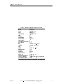
date: March 20, 1996
time: 12:00 AM
le: usnt.tex
CONTENTS
Contents
1
2
3
4
5
6
7
A
B
C
Introduction : : : : : : : : : : : : : : : : : : : : : : : : : : : : : : : : : : :
How to Install the Model : : : : : : : : : : : : : : : : : : : : : : : : : : : :
How to Run the Model : : : : : : : : : : : : : : : : : : : : : : : : : : : : :
Input Data Syntax : : : : : : : : : : : : : : : : : : : : : : : : : : : : : : :
Input Format : : : : : : : : : : : : : : : : : : : : : : : : : : : : : : : : : :
Input Data Documentation : : : : : : : : : : : : : : : : : : : : : : : : : :
init-eqts { Specify component and phase names : : : : : : : : : : : :
title, output-prefix { Title and output le prex : : : : : : : : : :
time, tstop, dt, dtmax, stepmax { Time step control : : : : : : :
tolerdt, reltolerdt { Time step control : : : : : : : : : : : : : : :
tolerconv, reltolerconv { Newton-Raphson convergence tolerances
genmsh { Generate mesh : : : : : : : : : : : : : : : : : : : : : : : : : :
state { Specify initial conditions : : : : : : : : : : : : : : : : : : : : :
rocktab { Material properties : : : : : : : : : : : : : : : : : : : : : : :
compprop { Component specic properties : : : : : : : : : : : : : : : :
phaseprop { Phase specic properties : : : : : : : : : : : : : : : : : :
generic { Generic properties : : : : : : : : : : : : : : : : : : : : : : :
restart { Read and write restart information : : : : : : : : : : : : : :
srctab { Source terms : : : : : : : : : : : : : : : : : : : : : : : : : : :
bctab { Boundary conditions : : : : : : : : : : : : : : : : : : : : : : :
output { Output options : : : : : : : : : : : : : : : : : : : : : : : : :
vapor-pressure-lowering { Vapor pressure lowering option : : : : :
6.1 Notes: Table Time Values : : : : : : : : : : : : : : : : : : : : : : : :
References : : : : : : : : : : : : : : : : : : : : : : : : : : : : : : : : : : : :
Sample Problem No. 1: Isothermal : : : : : : : : : : : : : : : : : : : : : :
Sample Problem No. 2: Thermal : : : : : : : : : : : : : : : : : : : : : : :
The Mathematical Model : : : : : : : : : : : : : : : : : : : : : : : : : : :
DRAFT
USNT-NUFT User's Manual (March 20, 1996)
:
:
:
:
:
:
:
:
:
:
:
:
:
:
:
:
:
:
:
:
:
:
:
:
:
:
:
:
:
:
:
:
:
:
:
:
:
:
:
:
:
:
:
:
:
:
:
:
:
:
:
:
:
:
:
:
:
:
:
:
:
:
:
:
:
:
:
:
:
:
:
:
:
:
:
:
:
:
:
:
:
:
:
:
:
:
:
:
:
:
:
:
:
:
:
:
:
:
:
:
:
:
:
:
:
:
:
:
:
:
:
:
:
:
:
:
:
:
:
:
:
:
:
:
:
:
:
:
:
:
:
:
:
:
:
:
:
:
:
:
:
:
:
:
:
:
:
:
:
:
:
:
:
:
:
:
:
:
:
:
:
:
:
:
:
:
:
:
:
:
:
:
:
:
:
:
:
:
:
:
:
:
:
:
:
:
:
:
:
2
4
6
7
13
14
14
16
17
18
20
21
24
28
34
38
40
41
43
46
48
54
55
56
57
62
68
1
1. INTRODUCTION
1. Introduction
This manual describes the USNT module of NUFT, which is a model solving the ow and transport equations under non-isothermal conditions of an N-phase system with arbitrary number of
components. The balance equations that are solved are given in Appendix C. Local thermodynamic equilibrium is assumed between chemical species using partitioning coecients. Vapor
pressure lowering of components is available as an option.
NUFT (Nonisothermal Unsaturated-Saturated Flow and Transport model) is a suite of multiphase, multicomponent models for numerical solution of non-isothermal ow and transport in
porous media with application to subsurface contaminant transport problems. These distinct
models are imbedded in a single code in order to utilize a common set of utility routines and
input le format.
Currently, the code runs on the Unix and DOS operating systems. Versions have been successfully compiled and tested for IBM-PC compatibles, Cray Unicos, and the following workstations:
Sun, Hewlett-Packward, IBM Risc/6000, Silicon Graphics, DEC Alpha. Each set of related models is called a module and has its own user's manual which documents any particular features
and input data specic to that module. The NUFT Reference Manual [Nitao, 1993] documents
the general numerical algorithms used and gives the documentation of the input to the model
common to all or most modules including options not described in the user's manual for each
module.
Available modules are:
{ unconned and conned saturated ow model
US1P { single phase unsaturated ow (Richard's equation)
US1C { single component contaminant transport
USNT { NP-phase, NC-component with thermal option.
UCSAT
An integrated nite-dierence spatial discretization is used to solve the balance equations. The
resulting non-linear equation is solved at each time by the Newton-Raphson method. Options for
solution of the linear equations at each iteration are direct banded solution and preconditioned
conjugate gradient method with various preconditioning schemes.
The model can solve one- , two- , or three-dimensional problems. Future plans include incorporation of capillary hysteresis, non-orthogonal mesh discretization, nite elements, non-linear
solid sorption isotherms, and chemical reactions.
The rst stage of code verication with one-dimensional problems has been completed (Lee et
al., [1993]) and further verication eorts are planned.
The distinct models in the code utilize a common set of utility routines and input le format.
The various models are essentially isolated from each other and hence future models can be
added without aecting existing models. This also allows for easy maintenance and future
enhancements. Global variables in the code are virtually non-existent. The code is written
principally in the C language. Input data is in the form of that used by the lisp language. An
internal lisp interpreter for the Scheme dialect of lisp is part of the simulator whose purpose is
to read the input data le and the internal data les containing default input data values. It
also performs data checking.
This manual is self-contained and describes a minimal set of the most commonly used input
parameters necessary for the use of this module. The NUFT reference manual (Nitao, [1995])
DRAFT
USNT-NUFT User's Manual (March 20, 1996)
2
1. INTRODUCTION
contains generic input options common to all of most of the modules. It also contains further
input options not given in this manual.
acknowledegments
The author wishes to thank the management of the Environmental Restoration Division at
the Lawrence Livermore National Laboratory (LLNL) for supporting the documentation and
verication of the NUFT code. The basic concepts of the code was developed under the funding
of the LLNL Institutional Research and Development program.
DRAFT
USNT-NUFT User's Manual (March 20, 1996)
3
2. HOW TO INSTALL
2. How to Install the Model
Installation onto a Unix System
The distribution of NUFT for the Unix operating system (Cray Unicos and unix workstations)
comes with a C-shell installation script called INSTALL-SCRIPT and a compressed tar le.
The name of the compressed tar le is of the form xxx.tar.Z where xxx are characters referring
to the NUFT version number. Copy these two les to any directory (for example, your home
directory).
1. Type:
csh INSTALL-SCRIPT tar-file
2. The directory bin just below your home directory must be placed as part of your execution
path by editing the PATH variable that is usually set in the .login le in your home
directory, if it is not already there. For example,
PATH = .:$HOME/bin:/bin:/usr/bin:/ucb/bin
3. The installation script and the tar le can be deleted after successful installation. See
below for the location of the tar le after installation.
The installation script will create directories bin and NUFT below your home directory unless
they exist already. The installation script creates a directory with the name xxx below the
NUFT directory derived from the name of the compressed tar le xxx.tar.Z. It then copies
the compressed tar le and extracts its contents into this directory. It then symbolically links
the le nuft to the le nuft-dist in the installed directory. This is the le that your system
executes when you type the nuft command which runs the model. NUFT sample input les are
also placed into the installed directory.
The script does not remove the directories containing older NUFT versions. The user may delete
older versions if they wish. The installation script will give a message indicating whether the
installation was successful. After successful installation, the model is ready to run. See the next
section in order to run the model.
Installation for IBM-PC Compatibles under DOS
The NUFT distribution for IBM-PC Compatibles under DOS comes on a oppy disk with an
installation script called install.bat.
1. Type:
a:\install.bat
with the oppy in the a: drive.
2. The directory \nuft must be placed as part of your execution path by editing the PATH
variable that is set in the autoexec.bat le in the top directory, if it is not already there.
For example,
PATH=C:.;C:\;C:\DOS;\nuft
The installation script will create directories \nuft below your home directory unless it exists
already. The installation script then creates a directory with the name xxx equal to the NUFT
DRAFT
USNT-NUFT User's Manual (March 20, 1996)
4
2. HOW TO INSTALL
version number and copies the appropriate les there. A le called nuft.bat is copied to the
\nuft directory. This is the le that your system executes when you type the nuft command
which runs the model. NUFT sample input les are also placed into the installed directory.
The script does not remove the directories containing older NUFT versions. The user may delete
older versions if they wish. The installation script will give a message indicating whether the
installation was successful. After successful installation, the model is ready to run. See the next
section in order to run the model.
DRAFT
USNT-NUFT User's Manual (March 20, 1996)
5
3. HOW TO RUN
3. How to Run the Model
Steps to Run the Model:
1. Install the code. See the previous section on how to install the code.
2. Specify the mesh. The mesh can be created through either of the following methods.
Using the genmsh option in the input le
Using an external program that creates a mesh le (see the NUFT reference manual
for description of the mesh le format).
The rst option is recommended for new users.
3. Create the input data le. The input le is created using any ascii text editor. An
editor such as vi or emacs which signals matching parentheses is preferable. You will need
to read section on the input data syntax to understand the general format of the types
of input data that goes into the input le. For rst time users it is easiest to edit the
preexisting sample input les provided with the code distribution.
4. Run the model. Type:
nuft
DRAFT
input-le
USNT-NUFT User's Manual (March 20, 1996)
6
4. INPUT DATA SYNTAX
4. Input Data Syntax
DRAFT
USNT-NUFT User's Manual (March 20, 1996)
7
4. INPUT DATA SYNTAX
This section describes the syntax of the input data. The input data le format is in free format,
i.e. it does not matter what column the data is in, nor does it matter if the data is continued
past the current line or lines.
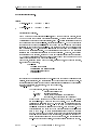
Input consists of lists of data blocks, or data units. Each data unit starts with a left parenthesis
and ends with a right parenthesis. A data unit is of the following general form:
<name> <data> <data> : : : )
(
where
<name> refers to the input \variable" that is being set or specied
<data> are items which are real numbers, integer numbers, time real numbers, strings,
pattern strings, words, or other data units, or list(s) of data items.
The dierent data types are dened later in this section.
An alternate form for a data unit is
( \ <name> <data> <data> : : : \ <name>)
An advantage of this form is that the model can more reliably tell the user the exact location
of any unmatching parentheses.
Example:
(porosity 0.2)
(file-name "input.data")
(par 0.1 0.3 0.6)
This example sets three dierent variables. It sets the variable porosity to the numeric value,
0.2, the variable file-name to the string, "input.data", and the variable par to a list of three
numeric values, 0.1 0.3 0.6.
Example:
(\rocktab
(silt (porosity 0.3) (Kx 1.e-4)(Ky 1.e-4)(Kz 1.e-4))
(sand (porosity 0.2) (Kx 1.e-2)(Ky 0.0)(Kz 0.0))
(clay (porosity 0.4) (Kx 1.e-6)(Ky 0.0)(Kz 0.0))
\rocktab)
This example shows how a data unit which sets the variable, rocktab, to a list of data units.
Comment Character: Semi-colons in the input le serve as comment characters. That is, all
characters on a given line after a semicolon are ignored by the program. Using comments is a
good way for the user to annotate his input le. Using two semicolons instead of a single one is
a good way to make sure that comments standout.
Example:
(porosity 0.2)
;; this is how we set the value of porosity to 0.2
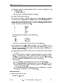
Units: All quantities are in MKS units (i.e. meters, kilogram, seconds). Thus, hydraulic
conductivities are in meters/second, and head is in meters (see Table 4). Unitless quantities
such as saturation, porosity, and concentrations are always fractional (i.e. between 0 to 1,
inclusive), not percentages.
Legal Data Types: We now describe the following valid data types.
DRAFT
USNT-NUFT User's Manual (March 20, 1996)
8
4. INPUT DATA SYNTAX
Table 1 Table of Units used in Input to Models
length
meters (m)
mass
kilograms (kg)
timey
seconds (s)
temperature
centigrade ( C)
area
m2
volume
m3
mass density
kg/m3
molar density
mole/m3
permeability
m2
hydraulic conductivity m/s
ow velocity
m/s
force
Newton (Nt=kg-m/s2 )
pressure
Pascals (Pa=Nt/m2 )
head
m
energy
Joule (J=Nt-m)
specic energy
J/kg
mass ux
kg/s
molar ux
mole/s
volumetric ux
m3 /s
energy ux
Watts (W=J/s)
thermal conductivity W-m/ C
dynamic viscosity
Nt-s/m2 =kg/m-s=103 centipoise
molecular diusivity m2 /s
ymodel can accept other time units using unit designators
DRAFT
USNT-NUFT User's Manual (March 20, 1996)
9
4. INPUT DATA SYNTAX
1. A string is any sequence of visible characters delimited by double quotes \"", for example,
"hello there"
" run3-B (test#2) "
Note that spaces and parentheses are allowed in a string.
2. An integer number, for example, 11.
3. A real number that is xed or oating point. For example 1.23, -4.5e7, or 900.2E7.
Note that D or d exponents in the manner of FORTRAN are not allowed !
4. A time number which is a real number but with with the following unit designators as the
last letter in order to denote units of time. As you may have guessed, this type of number
is used whenever we want to specify a time.
s
m
h
d
M
y
seconds
minutes
hours
days
months
years
If no unit designator is present, then seconds is assumed.
Examples:
20.0
20 seconds
23.1s
23.1 seconds
45e4M
45e4 months
There must be no spaces between the number and the unit designator.
5. A word is a sequence of non-blank visible characters. A word can be a variable or may be
used in the same way as a string except that it can not have internal blanks. The model
treats the words and strings as being distinct data types; the correct one as specied in
the documentation is required.
6. A pattern string is a special type of a string with the two unix shell type \wild" characters
* and ?
so that a pattern string can represent an entire class of strings that matches the string
pattern. The character * in a pattern matches any sequence of characters. Hence, the
pattern "*" matches all strings. The character ? in a pattern matches any single character.
Hence, the patter "?" matches all strings with exactly one character.
Other Examples:
1. The pattern "ex*" matches all strings that begin with the characters "ex".
2. The pattern "ex*b2*z" matches all strings that begin with "ex", followed by any
number (including zero) of strings which are then followed by the string "b2", and
which end with the string "z".
3. The pattern "r2?xay" matches all strings that begin with "r2" followed by a single
character, and then followed by the characters "xay".
Include statement:
The include statement is of the form
(include "<le-name>")
DRAFT
USNT-NUFT User's Manual (March 20, 1996)
10
4. INPUT DATA SYNTAX
It is used to place the contents of the le with the name, "<le-name>", into the input le.
The le must lie in the working directory under which NUFT is being run. It can only be used
to replace a complete list, i.e. must be either a collection of data which is delimited by a closed
sets of parentheses or a single data item such as a number or string. For example, suppose the
le "data1.inc"contains
(field (format list) (range "*") (variables Sl)(file-ext ".Sl")
(outtimes 0 70m 102m 222m 287m 342m 23h)
)
and the le "data2.inc"contains the single entry
200m
with the le "data3.inc"containing the string
".Sl"
Then, the following input data
(output
(include " data1.inc")
(forcetimes (outtimes (include " data2.inc" 201m))
)
will be interpreted by the model as begin equivalent to
(output
(field (format list) (range "*") (variables Sl)(file-ext ".Sl")
(outtimes 0 70m 102m 222m 287m 342m 23h)
)
(forcetimes (outtimes 200m 201m))
(file-ext ".Sl")
)
The following is an example of an error. Suppose the le "le.inc"contains the following
(outtimes 0 70m 102m 222m
and the input le as the data item
(output
(field (format list) (range "*") (variables Sl)(file-ext ".Sl")
(include " file.inc") 287m 342m 23h)
)
(forcetimes (outtimes 200m 201m))
(file-ext ".Sl")
)
DRAFT
USNT-NUFT User's Manual (March 20, 1996)
11
4. INPUT DATA SYNTAX
This is an error because only complete lists or a single entry can be included (not to mention
the fact that the parentheses will not match in the input le).
Include package statement:
The include package statement is of the form
(include-pkg "<le-name>")
This statment is identical to the include statement except that it includes a le from the
subdirectory which contains the NUFT executable instead from the current working directory.
The main purpose is to include a `package' of pre-dened input parameters which comes with
the NUFT software distribution.
Macro commands:
Macro commands start with the character `#'. There are three commands available: #define,
#ifdef, and #ifndef. The following command denes a macro variable,
(#define <variable>)
Currently, a variable cannot be dened to be any particular value, but it is used in conjunction
with the other macro commands. The statements within
(#ifdef <variable> .... )
will be placed as part of the input stream if <variable> is dened by the #define command;
whereas, the statements within
(#ifndef <variable> .... ) will not be placed as input if <variable> is not dened. The
#define statements must be in the same parenthesis level as, for example, bctab, genmsh, etc.
The #ifdef and #ifndef commands can be placed anywhere, except that the body of statements
in the conditional commands must be complete lists, i.e. parentheses match inside the macro
command. Currently, the macro commands only work inside an input set for a module or inside
common.
DRAFT
USNT-NUFT User's Manual (March 20, 1996)
12
5. INPUT FORMAT
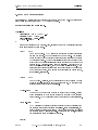
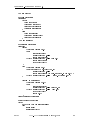
5. Input Format
Before going further the user should read the section on the input data syntax.
Form of Input Data
(usnt
(init-eqts
)
(title
)
(output-prefix
(time
)
(tstop
)
(dt
)
(dtmax
)
(stepmax
)
(tolerdt
)
(reltolerdt
)
(tolerconv
)
(reltolerconv
(genmsh
)
(read-restart
(state
)
(compprop
)
(phaseprop
)
(generic
)
(rocktab
)
(output )
(srctab
)
(bctab
)
)
:::
:::
:::
:::
:::
:::
:::
:::
:::
:::
:::
:::
:::
:::
:::
:::
:::
:::
:::
:::
:::
;;
;;
)
;;
;;
;;
;;
;;
;;
;;
;;
)
:::)
;;
;;
;;
;;
;;
;;
;;
;;
set names of components and phases
run title
;; prefix of all output files
initial time
ending time
initial time step size
maximum time step
maximum no. of time steps
absolute time step control
relative time step control
absolute Newton-Raphson convergence criteria
;; relative Newton-Raphson convergence criteria
;; mesh specification
;; read initial data from restart file
set initial conditions
component dependent property values
phase dependent property values
generic property values
porous medium properties
output specification (optional)
source term tables (optional)
boundary condition tables (optional)
The `: : :' denote data which will be explained later. All input past a semicolon on a given line
is treated as comments. The above data units can occur in any order except for the word usnt
which must come rst. Either state or read-restart must be present, but not both. The items
(output : : : ), (srctab : : : ), and (bctab : : : ) are optional; the rest are required. There are
other optional data items not shown above that are described in the NUFT Reference Manual
(Nitao, [1995]).
DRAFT
USNT-NUFT User's Manual (March 20, 1996)
13
6. INPUT DATA DOCUMENTATION
init-eqts
6. Input Data Documentation
In this section we describe all of the basic input data needed to run the model. Some less widely
used options are documented in the NUFT Reference Manual.
Specify component and phase names.
(init-eqts
(components
comp
comp
(phases phase
phase
)
(wetting-phase wetting-phase )
( thermal-option )
)
<
<
<
><
> :::)
><
> :::
<
>
>
Set names of phases and components. Also, species whether the model is isothermal or
thermal and sets the wetting phase.
<comp>
word
<phase>
word
Name of component. NUFT solves the coupled set of balance equations
for each component. The components can be in any order. The ordering
can impact some of the other input parameters which refers to components
by this tacit ordering. The component energy should not be specied here
even though the model internally uses this component name when the model
is thermal (i.e. <thermal-option> is set to thermal). Although one may
give the components any name, some components have signicance. When
using equation of state options specic to an \air" (pseudo) component or
to a \water" component, one must use the appropriate component names,
air or water, respectively.
Name of phase. Currently, the model require one of the phases to be a gas
phase, so that gas should be one of the phase names. An aqueous phase
should be called either liquid or aqueous.
<wetting-phase> word
The name of the uid phase which is in contact with the solid, withing
which partitioning of a component occurs with the solid due to sorption
onto the solid. The Kd values are dened with respect to this partitioning.
<thermal-option> word
NUFT will solve the balance equation for energy in order to calculate the
temperature if this parameter is set to thermal. If set to isothermal, the
energy balance equation is not solved. For the thermal option, the initial
temperature is set by state data item. For isothermal models, the initial
temperatures are set in the generic data item.
Example:
DRAFT
USNT-NUFT User's Manual (March 20, 1996)
14
6. INPUT DATA DOCUMENTATION
init-eqts
(init-eqts
(components water air TCE)
(phases aqueous gas NAPL)
(wetting-phase liquid)
(isothermal)
)
DRAFT
USNT-NUFT User's Manual (March 20, 1996)
15
6. INPUT DATA DOCUMENTATION
init-eqts
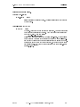
Title and output le prex.
<run-title>")
"<run-title>"
string
string containing the title of the run. The string will be placed in the header
of output les.
(title "
<prex>")
(output-prefix "
<prex>"
"
string
Optional. All output le names will have this prex. All output les will
have this prex unless set to otherwise. The main output le has this prex
with sux \.out". Example: setting
(output-prefix "runA")
will set the main output le name to be called \runA.out". Other auxillary
output les can be created from separate suxes set by the file-ext parameter in the various output options possible using the output data unit.
Default is to use the prex of the input le name. For example if the input
le is called runA.3.in, then the output les have the prex runA.3, such
as runA.3.out.
DRAFT
USNT-NUFT User's Manual (March 20, 1996)
16
6. INPUT DATA DOCUMENTATION
init-eqts
Time step control.
<start-time>)
<start-time>
t-real
initial starting time of run. For restarts, this time is not needed if restart
is set, in which case the initial time will be set to the time read in through
the restart le. If time appears, this overwrites the time read in.
(time
<stop-time>)
<stop-time>
t-real
run will stop when it reaches this time.
(tstop
(dt
<initial-time-step>)
<initial-time-step>
t-real
initial time step size.
<max-step-size>)
<max-step-size>
t-real
maximum time step size.
(dtmax
<max-steps>)
<max-steps>
integer
maximum number of time steps; run will stop if this will be exceeded.
(stepmax
DRAFT
USNT-NUFT User's Manual (March 20, 1996)
17
6. INPUT DATA DOCUMENTATION
tolerdt, reltolerdt
Time step control.
(tolerdt (P
(T
)
<tolerdt-P>)
<tolerdt-T>)
(S
<tolerdt-S>)
(C <tolerdt-C>)
present only for thermal models
Set absolute tolerances for time step control.
<tolerdt-P> real
<tolerdt-S> <tolerdt-S>: : : reals
<tolerdt-C> <tolerdt-C>: : : reals
<tolerdt-T> real
The model will control time step such that the magnitude of changes in
the primary variables: gas pressure P (Pa), saturations S (fraction), mole
fraction concentrations C (mole fraction), and temperature T (deg. C) from
one time step to the next does not exceed the specied values. The tolerance
for the saturation of a particular phase or the concentration of a particular
component can also be specied and overwrites the general value set by S
or C. For example,
(tolerdt (P 1e3) (S 0.25) (S.liquid 0.1) (C 0.01) (C.TCE 1e-7))
sets the tolerance for the liquid saturation to 0.1 and 0.25 for all other phases
and the tolerance for concentration of the component TCE to 1e-7 and all
other concentrations to 0.01. As a rule of thumb the tolerances should be
about one to two orders of magnitude larger than the desired accuracy of
the primary variable. Recommended tolerances for pressure is 0.2 times the
maximum initial pressure. Tolerance for saturations is 0.25, concentrations
0.2 and temperature 15 degrees. Tolerances for some concentrations such
as for a low level contaminant may have to be much lower.
(reltolerdt (P
(T
)
<reltolerdt-P>)
<reltolerdt-T>
(S
<reltolerdt-S>) (C <reltolerdt-C>)
present only for thermal models
Set relative tolerances for time step control. The model calculates a time step based on
the absolute tolerance set in tolerdt and another time step based on relative tolerances
set in reltolerdt and uses the larger of the two.
<reltolerdt-P> real
<reltolerdt-S> <reltolerdt-S>: : : reals
<reltolerdt-C> <reltolerdt-C>: : : reals
<reltolerdt-T> real
The model will also control time step such that the relative magnitude of
changes in the primary variables: gas pressure P, saturations S, and concentrations C from one time step to the next does not exceed the specied
values. For each primary variable the model calculates the largest magnitude over all the elements in the entire problem domain and then multiplies
by the specied relative tolerance to get a maximumchange. Recommended
DRAFT
USNT-NUFT User's Manual (March 20, 1996)
18
6. INPUT DATA DOCUMENTATION
tolerdt, reltolerdt
tolerance for pressure is 0.2, saturation 0.0, concentration 0.2, temperature
0.0. Note that a zero tolerance causes the model to ignore relative tolerances and use the absolute tolerance. In the same way as for the tolerdt
statement, tolerances for saturations of specic phases and concentrations
of specic components can be set.
DRAFT
USNT-NUFT User's Manual (March 20, 1996)
19
6. INPUT DATA DOCUMENTATION
tolerconv, reltolerconv
Newton-Raphson convergence tolerances.
(tolerconv (P
(T
)
<tolerconv-P>) (S <tolerconv-S>) (C <tolerconv-C>)
<tolerconv-T>) present only for thermal models
Sets tolerances for Newton-Raphson iteration convergence criteria. The model checks for
convergence using both the tolerconv and reltolerconv parameters. Convergence is
assumed if either one of the criteria is true for each primary variable.
<tolerconv-P> real
<tolerconv-S>: : : reals
<tolerconv-C>: : : reals
<tolerconv-T> real
Absolute criteria for convergence of the Newton-Raphson iterations for solution of the non-linear, implicit-in-time, discretized balance equations is
acheived if the magnitude of the changes in the primary variables: gas
pressure P (Pa), saturations S (fraction), concentrations C (mole fraction),
and temperature T (deg. C) from one iteration to the next is less than or
equal to these values. Recommended tolerance for pressure is 0.0001 times
the maximum initial pressure, for saturation is 0.001, for concentration is
0.0001, and temperature 0.01. The tolerance for a dilute component, such as
a contaminant, should have a much lower tolerance equal to 0.01 times the
the level of desired absolute accuracy. In the same way as for the tolerdt
statement, tolerances for saturations of specic phases and concentrations
of specic components can be set.
(reltolerconv (P
(T
)
<reltolerconv-P>) (S <reltolerconv-S>) (C <reltolerconv-C>)
<reltolerconv-T>) present only for thermal models
Sets relative tolerances for Newton-Raphson iteration convergence criteria. The model
checks for convergence using both the tolerconv and reltolerconv parameters. Convergence is assumed if either one of the criteria is true for each primary variable.
<reltolerconv-P> real
<reltolerconv-S> <reltolerconv-S>: : : reals
<reltolerconv-C> <reltolerconv-C>: : : reals
<reltolerconv-T> real
Criteria for Newton-Raphson convergence based on the maximum relative
magnitude of changes in the respective primary variables. Recommended
values are 0.001 for pressure, 0.01 for saturation, 0.001 for concentrations,
and 0.001 for temperature. In the same way as for the tolerdt statement,
tolerances for saturations of specic phases and concentrations of specic
components can be set.
DRAFT
USNT-NUFT User's Manual (March 20, 1996)
20
6. INPUT DATA DOCUMENTATION
genmsh
Generate mesh.
(genmsh
(coord
mesh-type )
(down Vx
Vy
Vz )
(dx dx-1
dx-2
)
(dy dy-1
dy-2
)
(dz dz-1
dz-2
)
(mat
( el-name-prex
mat-type
<
>
< >< >< >
< > < > :::
< > < > :::
< > < > :::
<
><
>
<i0><i1> <j0><j1> <k0><k1>)
:::
(<el-name-prex><mat-type>
<i0><i1> <j0><j1> <k0><k>)
)
(anisotropic)
(wrap-around)
)
optional
species the mesh geometry, element material types and names.
<mesh-type>
word
species the type of mesh that will be generated. Valid options:
rect
rectangular mesh
cylind
cylindrical mesh
Let the three coordinates of our mesh system be x, y, and z. If the mesh
type is rect, then x, y, and z are along the coordinate axes of a rectangular
system. If mesh type is cylind, then the rst coordinate x is the radial
distance r, the second coordinate y is angle , and the third coodinate z is
the longitudinal axis.
<Vx> <Vy> <Vz> reals
are the components of the vector pointing downward in the direction of the
gravity vector. The program will internally normalize the vector to unity.
Setting the components to all zero will turn o gravity in the model. The
vector is always with respect to a rectangular coordinate system (X; Y; Z).
For a rectangular mesh, the coordinate system coincides with the rectangular coordinate system (x; y; z) of the mesh. If the mesh is cylindrical, the
vector is with respect to a coordinate system (X; Y; Z) where X is the axis
dened by = 0; z = 0; Y is the axis dened by = 90; z = 0, and the
axis Z is dened by r = 0.
<dx-1> <dx-2> : : : reals
are the subdivisions of the mesh in the direction of the rst coordinate x.
For a rectangular mesh, the subdivisions are in the increasing x direction of
the rectangular coordinate system of the mesh. For a cylindrical mesh, the
subdivisions are in the increasing r direction. Numbers that are repeated
can be abbreviated; for example, 3*5.0 would stand for three repeats of
the numeral 5, that is, 5.0 5.0 5.0.
<dy-1> <dy-2> : : :
DRAFT
reals
USNT-NUFT User's Manual (March 20, 1996)
21
6. INPUT DATA DOCUMENTATION
genmsh
are the subdivisions of the mesh in the direction of the rst coordinate
x. For a rectangular mesh, the subdivisions are in the increasing y direction. For a cylindrical mesh, these parameters set the subdivisions in the
increasing direction. Angular units are in degrees. The cylindrical mesh
wraps completely around the direction only for the case of a single angular
subdivision whose value is equal to dy-1 = 360).
<dz-1> <dz-2> : : : reals
are the subdivisions of the mesh in the increasing z direction for either a
rectangular or cylindrical mesh system.
<el-name-prex>
word
prex of element name. Each element in the specied i; j; k index range
will a name comprised of this prex and a number associated with it as
the sux (see the explanation of index ranges below for examples). This
prex can be used to specify a range of elements in the state, output,
and other input parameters. The element names will be of the form <elname-prex>#<i>:<j>:<k> where <i>,<j>,<k> denote the i, j, and k
indices.
<mat-type>
word
material type. Each element in the specied i; j; k range will have this material type (see the explanation of index ranges below for examples). Each
material type must have a corresponding entry in the material type table in
rocktab. An exception are material types that are pre-dened in the model.
At this time, the only pre-dened material type is NULL which completely
removes the respective element or elements from the model. An equivalent
method of removing elements is the null-blocks option describedin the
NUFT Reference Manual. Material types that are of the following form
denote specic `auxillary' elements used for boundary conditions,
BC.1.xxx element for b.c. of rst type,
BC.2.xxx element for b.c. of second type,
BC.3.xxx element for b.c. of third type.
An element for rst and third type boundary conditions will have zero ow
connection from the element centroid to the boundary of any neighboring
non-auxillary elements. An element for a second type boundary condition
will have ow connection set to unity so that the reciprocal of the permeability or hydraulic conductivity will be the resistance, and the volume
of the element is set to the average volume of neighboring non-auxillary
elements.
<i0> <i1> <j0> <j1> <k0> <k1>
integers
species a range of elements using the i; j; k indices of the element in the
direction of the x; y; z directions. Used to specify the range of elements
for setting element name prexes <el-name-prex> and the material types
<mat-type>. A specication record of the form,
(<el-name-prex><mat-type><i0><i1><j0><j1><k0><k1>)
will overwrite the eect of any previous records (see example
below). In this way, one can specify non-rectangular regions to have the
same element prex or material type.
The i; j; k indices are consistent with the dx, dy, and dz parameters. That is,
DRAFT
USNT-NUFT User's Manual (March 20, 1996)
22
6. INPUT DATA DOCUMENTATION
genmsh
the dx parameter species the x dimension of the elements for (i = 1; 2; : : :),
in that order. Similarly, dy species the y dimensions of the elements for
(j = 1; 2; : : :), and dz species the z dimensions for (k = 1; 2; : : :).
Example:
(e silt 2 4 3 10 1 8)
This example species that the elements in the index range (i = 2 to 4),
(j = 3 to 10), and (k = 1 to 8) will have element names e1, e2, : : : and
will be of material type silt.
Example:
consider a mesh with 4 elements in the i direction, 3 elements in the j
direction, and 5 elements in the k direction,
(mat
(s
silt
1 4
1 3
1 5)
;;
;;
(c clay 1 4 1 3 2 2)
;;
(w well 2 2 3 3 2 2)
;;
;;
(aquif silt 1 4 1 3 5 5) ;;
;;
first set all elements
to silt
make layer k=2 into clay
make i=2,j=2, k=2 into
well element
call lowest layer by
different prefix
)
The symbols nx, ny, and nz can be used anywhere in place of a number
where an index is required. The model interprets these to mean the number
of subdivisions in the x, y, and z directions, respectively.
(anisotropic)
this parameter is optional. (The older form of the parameter isot-dir can
also be used instead.) Aects the choice of the permeability (or hydraulic
conductivity) parameter. See the documentation of the parameters Kx,
Ky, and Kz below. This parameter should not be present for models where
isotropic permeability (or hydraulic conductivity) is desired unless the three
permeability parameters for each material type are equal.
(wrap-around)
if present, model wrap the grid around in the angular direction. I.e. for
each element at j = 1 connect to the corresponding adjacent element at
j = ny where ny is the number of elements in the j direction. Default is
no wrap-around.
DRAFT
USNT-NUFT User's Manual (March 20, 1996)
23
6. INPUT DATA DOCUMENTATION
state
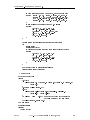
Specify initial conditions.
(state
(
)
<state-var-name> <method> <data>)
:::
(<state-var-name> <method> <data>)
Set initial state variables.
Let NP be the number of phases in init-eqts, let NC the number of components, and let
NPNZ be the number of phases with nonzero saturation. The state variables which must
be initialized at each element are: gas pressure, rst NP-1 nonzero saturations in order of
the phases as they appear in init-eqts, concentrations of last NC-NPNZ components (in
the order as they appear in init-eqts) in the phase which is the rst one with nonzero
saturation in the order given in init-eqt. For thermal models, the temperature must
also be initialized. The NP-th saturation is internally computed from the constraint that
the sum of the saturations is unity. The concentrations of the rst NPNZ components is
calculated from conditions for local thermodynamic equilibrium. Note that, not counting
the saturation which are zero, there are NC primary variables for isothermal models and
NC+1 primary variables for thermal models. This is the same number as the number of
balance equations for each component and for energy.
For example, consider a system with two phases, liquid and gas, and three components,
air, water and a contaminant,
(init-eqts
(phases liquid gas)
(components air water contam)
(wetting-phase liquid)
(isothermal)
)
If the liquid and gas saturations are both non-zero then the primary variables are gas
pressure, liquid saturation, and concentration of the contaminant in the liquid phase. If
the liquid saturation is zero then the primary variables are gas pressure and concentration
of water concentration of contaminant, both in the gas phase.
<state-var-name> word
The valid primary, or state, variable names are
P
absolute gas pressure (Pa)
S.<phase>
saturation (fraction)
C.<comp>
contaminant concentration (mole fraction)
T
temperature, if model is thermal (Centigrade)
where <phase> is the name of a phase which is one of the rst NP-1 phases
set in init-eqts, NP being the number of phases. The model internally
calculates the saturation of the NP-th phase from the constraint that the
saturations must sum to unity. <comp> is a name of a component set in
init-eqts (excludes the energy \component"). Only the last NC-NPNZ
concentrations in the order of the components occuring in init-eqt are
used by the model. The other concentrations should be set to a negative
number. In this way the model can check to see if the concentration is really
needed in that if it is needed and it is negative, it will let the user know by
giving a fatal error message in the main output le. If a concentration is
non-negative but is not necessary, a warning message is ashed to output.
DRAFT
USNT-NUFT User's Manual (March 20, 1996)
24
6. INPUT DATA DOCUMENTATION
state
If a saturation is initialized to a value greater than the maximum liquid
saturation (as set in rocktab), then it is reset by the model to that value.
If the saturation is set to a value less than zero, it is reset to zero.
<method>
<data>
word
chooses the format by which the initial conditions will be set. See below
for valid formats.
Valid data formats are:
("<elem-range>"<value>)
initialize elements that are within the element range.
"<elem-range>"
pattern string elements whose names match this
pattern will be set to the specied value. <value> real
elements in the specied range will have this value for the specied primary variable.
by-key
Example:
sets the initial value of the variable, C, to
0.1 for all elements whose names begin with the characters el.
(C by-key ("el*") 0.1)
by-set
<vector>
initialize all components of the vector holding the . Ordering
of vector is relative to internal ordering done by code. Used
for transfering values from an output from a previous run.
<vector> = [#<n> <v0> <v1> : : : ]
where <n> is no. of elements (the #<n> eld is optional)
and <v0> <v1> : : :are of type real and are the initial values. Here, [and ]are actual characters and do not represent
delimiters of optional parameters
Example:
(Sl by-set [#3 3.
4.
1.])
Sets the variable Sl to the values 3., 4., 1. for element numbers 1,2, and 3, respectively.
by-xtable
by-xtable
<table> or
(range "<elem-range>") <table>
sets initial condition by interpolating from a table of values
specied at given values of the x coordinate.
"<elem-range>" is an optional range of elements whose state
variable will be set. Default is all elements.
<table> is a table of values with respect to the appropriate
x,y, or z coordinate. The table is of the form:
(<x0> <val0> <x1> <val1> : : : ) or <x0> <val0> <x1>
<val1> : : : where <x0> <x1> : : :are the values of the x
coordinate and <val0> <val1> : : :are the values of the primary variable that is being initialized. Values are calculated
DRAFT
USNT-NUFT User's Manual (March 20, 1996)
25
6. INPUT DATA DOCUMENTATION
state
using linear interpolation based on the coordinates of the element centroids. Centroid coordinates are derived from the
subdivisions specied in dx, dy, and dz parameters. The coordinates of the edges of the model start at zero, so that, the
x coordinate for the element centroids for i = 1 are x =<dx1>/2, those for i = 2 are x =<dx-1> + <dx-2>/2 and so
on. The y coordinate for the element centroids for j = 1 are
y =<dy-1>/2, those for j = 2 are y =<dy-1> + <dy-2>/2
and so on, and, similarly, for the z coordinates.
by-ytable
sets initial condition through a table of values versus the y
coordinate.
by-ztable
sets initial condition through a table of values versus the z
coordinate.
A state variable can appear more than once to overwrite values set by previous specication
records. It is often convenient to set the values for all elements by by-ztable or by-set
and then modify values for specic elements using by-key). For example,
(state
(C by-ztable (0.0 0.0
1. 2.
(C by-key ("abc*" 0.0))
(C by-key ("*D*" 1.0))
)
10 2.))
The rst record initializes the variable C by a table given with respect to the z coordinate of
the element centroid. The second record overwrites the value of C to 0.0 for those elements
whose names (set by the genmsh input parameters) begin with the characters abc. The
third record overwrites the value to 1.0 for those elements whose name contains the letter
D.
NOTES:
1. A state variable can appear more than once to overwrite values set by previous
specications; for example, values for all elements can be set by \by-xtable" or
\by-set" and then \touched up" using \by-key)".
2. The program will terminate if a primary variable has not been set for all of the
elements.
Example:
Consider a system with two phases and three components as specied by
(init-eqts
(phases liquid gas)
(components air water contam)
(wetting-phase liquid)
(isothermal)
)
Example of how initial conditions can then specied is given by the following:
(state
(C.contam by-ztable
DRAFT
USNT-NUFT User's Manual (March 20, 1996)
26
6. INPUT DATA DOCUMENTATION
state
;; height
;; above
;; WT
C.contam
(0.0
0.0
0.2
0.001
0.8
0.01
1.0
0.01
10.0
0.0
)
)
(C.water ("*" -1.0) ("atm*" 0.02))
(S.liquid
;;
;;
;;
by-ztable
height
above
WT
S.liquid
(0.0
1.0
0.2
0.9
0.8
0.5
1.0
0.4
10.0
0.3
)
)
(S.liquid by-key ("bc*" 1.0))
(S.liquid by-key ("atm*" 0.0))
(P by-key ("*" 1.e5))
)
In this example, the concentrations C.contam are S.liquid are rst initialized by interpolating from tables specifying values vs. height above the water table. Then, liquid
saturation is for elements with names starting with the characters "bc" is set to unity and
those with leading characters "atm" is set to zero. The water component concentration is
required for the elements with zero liquid saturation and is set to 0.02. All other elements
are set to a negative number to let the model check whether we have overlooked anything
if they are needed. The pressure of all of the elements is initialized to 1.e5 Pa.
DRAFT
USNT-NUFT User's Manual (March 20, 1996)
27
6. INPUT DATA DOCUMENTATION
rocktab
Material properties.
(rocktab
<rock-type name>
(
(porosity
(Kd (
<porosity>)
<comp> <Kd>) (<comp> <Kd>) : : : )
<phase> <tort-parameters>)
:::
(<phase> <tort-parameters>))
(tort (
(Kx
<perm-x>)
(Ky
<perm-y>)
(Kz
<perm-z>)
<phase> <pc-parameters>)
:::
(<phase> <pc-parameters>))
(pc (
<phase> <kr-parameters>)
:::
(<phase> <kr-parameters>))
(kr (
following are needed only if model is non-isothermal
(Cp
<Cp>)
(solid-density
<
<solid-density>)
>
(tcond tcond-option
(solid tcond-solid )
( phase
tcond-sat )
<
><
<
>
> : : : (<phase> <tcond-sat>))
<comp> <KdFactor-parameters>)
:::
(<comp> <KdFactor-parameters>))
(KdFactor (
)
:::
<rock-type name>
(
:::
)
)
Set material properties for ow model. Each element has a porous medium material property type specied in the genmsh data item. The model references this type when it
calculates various contitutive properties which depend on the material type such as charDRAFT
USNT-NUFT User's Manual (March 20, 1996)
28
6. INPUT DATA DOCUMENTATION
rocktab
acteristic curves, porosity, etc.
<rock-type-name> word
Name of the material. Can be any name.
<porosity>
<Kd>
real
real
The fractional porosity of the material. Needs to be a number greater than
zero, otherwise the system will of equations solved by the model becomes
mathematically singular.
Dimensionless solid sorption coecient of the component dened as the
quantity B kd = where B is bulk dry density (g/ml), kd is the standard
solid sorption coecient (ml/g), and is porosity. Given a soil sample,
kd = !s=C where !s is g of component sorbed on the solid divided by
the mass of the solid in the sample in units of grams and C is g of
component dissolved in the wetting phase divided by the volume of the
phase in ml. If B is given in units of g/ml then B kd = Cs =C where Cs
is g of sorbed component divided by the bulk volume of the sample in ml.
It is well known that R = 1 + B kd = where R is the \retardation factor"
for ow when the porous medium is saturated by the wetting uid. Thus,
B kd = = R 1.
<tort-parameters> real
Parameters for calculating tortuosity factor for <phase> which used is
the factor multiplying the free molecular diusion coecient in calculating
the diusive ux of a component. The diusion ux is given by
q = S D r!
q mass ux
mass density of phase
S saturation
D free diusion coecient for component
! mass fraction
Following are valid options:
<real-value>
Constant value. Usually greater than or equal to zero and
less than or equal to one. Setting to zero will turn o diusion of all components in <phase>.
Millington
Millington formulation given by
= S7=3 1=3:
DRAFT
USNT-NUFT User's Manual (March 20, 1996)
29
6. INPUT DATA DOCUMENTATION
<perm-x>
<perm-y>
<perm-z>
rocktab
real
real
real
Intrinsic absolute permeability (m2) of the material. The model normally
will use only the value of <perm-x>. The other two values are ignored
although they must be present and can be set to zero. However, if the
parameter anisotropic or isot-dir is present in data unit genmsh, then
the value of <perm-x> will be used for ow in the rst coordinate direction
(for example, x-axis direction for rectangular coordinates and r-axis for
cylindrical), <perm-y> will be used for the second coordinate direction (y
or ), and <perm-z> for the third coordinate direction (z).
<pc-parameters> list of data units
Parameters for calculating the pressure dierence (\capillary pressure") between the gas phase and a nongas phase
pc = pg p ; 6= g
as a function of the saturations. An entry for pc.<phase> is needed only
for <phase> over all nongas phases. Valid options are
<real>
Constant value. A zero value is used to simulate an element
that is in a non-porous medium where the phase pressures
are equal.
< >
<alpha>) (Sj <Sj>)
< >
<
>
Van Genuchten formulation.
<m>
Parameter (unitless).
pcVanGen (m m ) (alpha
(Sr Sr ) (Smax Smax )
<alpha>
<Sj>
<Sa>
<Sr>
<Smax>
DRAFT
(Sa
<Sa>)
Parameter (1/Pa).
Optional. Transition saturation below which a linear
curve is used. The default is Sj = Sr+0:05 (Smax
Sr).
(optional) A linear function will be used for liquid saturation greater than <Sa> and less than or equal to
the maximum saturation to avoid the innite slope at
maximum saturation. Default is 0.999 times the maximum saturation.
Residual saturation.
USNT-NUFT User's Manual (March 20, 1996)
30
6. INPUT DATA DOCUMENTATION
rocktab
Optional maximum saturation. Default is unity.
<kr-parameters> list of data units
Name of the liquid relative permeability function vs. saturation function
and its associated parameters. Valid options are:
<real>
krlVanGen
krgVanGen
krfVanGen
Constant value. Usually between zero and one, inclusive. A
zero value can be used to shut o advective ow of the phase
exiting an element since the model uses upstream weighting
of the mobility factor kr = as the default.
<m>) (Sa <Sa>)
<m>) (Sa <Sa>)
<m>) (Sa <Sa>)
Van Genuchten formulation for aqueous, gas, and free hydrocarbon phase, respectively.
<m>
Parameter (unitless).
<Sa>
(optional) If (Sa <Sa>) is present, then a
linear function will be used for liquid saturation greater than <Sa> and less than or equal
to the maximum liquid saturation (= one minus the residual gas saturation) to avoid the
innite slope at maximum saturation. Default value is 0.999 times the maximum saturation.
(m
(m
(m
krgVanGenMinus
Calculates gas relative permeability as one minus the liquid
permeability. Used only for two-phase gas-liquid systems.
krlLinear
krgLinear
krfLinear
Linear relative permeability function for aqueous, gas, and
free hydrocarbon phase, respectively,
kr = (S Sr )=(Smax Sr ):
<Cp>
real
Specic heat of the solid (J/kg).
<solid-density>
DRAFT
real
USNT-NUFT User's Manual (March 20, 1996)
31
6. INPUT DATA DOCUMENTATION
rocktab
Solid grain density (kg/m3).
<tcond-solid>
<tcond-sat>
real
Bulk thermal conductivity of the porous medium (J/s-C) when there is no
uid at all in the pore space.
real
Bulk thermal conductivity of the porous medium (J/s-C) when the phase
denoted by <phase> completely lls the pore space.
<tcond-option> word
Options for calculating saturation dependent bulk thermal conductivity:
tcondLin
The total bulk conductivity is calculated using a linear weighting of saturations
kbulk = kdry +
NP
X
=1
S ksat:
tcondLin
A square root weighting is used,
kbulk = kdry +
NP p
X
=1
S ksat:
The bulk conductivity can be set to a constant value by using the form
(tcond <real-number>)
<KdFactor-parameters>
Parameters for temperature dependent factor multiplying the solid sorption
factor, Kd, for component <comp> (excluding energy component). Valid
parameters are:
<real>
real number. Value of 1.0 means no temperature modication.
<fac1>) (T1 <T1>) (T0 <T0>)
Units of temperatures <T0> and <T1> are in centigrade.
The factor is unity at temperature <T0> and equal to <fac1>
at temperature <T1>. At other values varies according to
the formula
KdFactorExp (fac1
factor = exp( A=TK )= exp( A=TK 0 )
DRAFT
USNT-NUFT User's Manual (March 20, 1996)
32
6. INPUT DATA DOCUMENTATION
rocktab
Here TK is temperature in Kelvin and TK 0 is <T0> converted to Kelvin. The parameter A is calculated from the
model by the constraint that the factor equals <fac1> at
<T1>.
DRAFT
USNT-NUFT User's Manual (March 20, 1996)
33
6. INPUT DATA DOCUMENTATION
compprop
Component specic properties.
(compprop
<comp>
(
(intrinsic
(MoleWt molewt )
(solidHalfLife solid-half-life )
)
<
>
<
<phase>
(
<
optional
>
(freeDiffusivity freeDi )
(Keq Keq-parameters )
(rhoC rhoC-parameters )
not used by gas
(enthC enthC-parameters )
required only by
(halfLife uid-half-life )
optional
<
<
<
)
>
>
<
>
>
>
phase
thermal models
:::
<phase>
:::
(
)
)
:::
<comp>
:::
(
)
)
set component dependent properties.
<phase>
word
<comp>
real
<molewt>
Name of phase.
Name of component (excluding energy component).
real
Molecular mass of the component (g/mole). (The model internally converts
this value to kg/mole)
<solid-half-life>
<uid-half-life>
DRAFT
real
real
USNT-NUFT User's Manual (March 20, 1996)
34
6. INPUT DATA DOCUMENTATION
compprop
Optional half life for rst order decay for the component adsorbed on the
solid phase and withing each of the uid phases. The model internally
calculates the decay constant separately for each of the phases from the
equation = ln(2)=half life The ability to set the half-life separately for
each phase is useful for bio or chemical degradation where decay may occur
at dierent rates in each phase.
<freeDi>
real
Free molecular diusion coecient of the component within the specied
phase (m2/s).
<Keq-parameters>
Parameters specifying the equilibrium partitioning coecient of a component. For a given component, a convenient reference phase should be chosen.
The coecient for reference phase is set to unity. All other coecients are
then dened with respect to the reference phase. That is, the coecient for
a component in phase, , is equal to the mole fraction of the component in
the phase divided by the mole fraction of the component in the reference
phase. Thus, if the liquid phase is chosen as the reference phase, the coecient for the gas phase is the ratio of the mole fraction in the gas to that of
the mole fraction in the liquid. To prevent mathematical singularities, the
coecients should be set to nonzero positive numbers. A singularity will
also result if there are two or more components which have the exactly the
same coecients. Valid options are:
<real-number>
Constant real number in mole/mole.
KeqStd (A
<A>) (B <B>) (C <C>)
For isothermal,
(D
<D>)
Keq = A + pg B + C=pg;
and for nonisothermal,
Keq = (A + pg B + C=pg) exp( D=TKelv)
where pg is gas pressure and TKelv is temperature in Kelvin.
The parameters <A>,<B>, and <D> are optional and default to zero. Assumes that the liquid phase is the reference
phase.
KeqTCESolute
Coecient for TCE in the gas phase. Assumes that the
liquid phase is the reference phase.
KeqWatVapor
DRAFT
USNT-NUFT User's Manual (March 20, 1996)
35
6. INPUT DATA DOCUMENTATION
compprop
Coecient for water vapor in the gas phase. Assumes that
the liquid phase is the reference phase.
<enthC-parameters>
Parameters for calculating specic enthalpy of the component.
Valid options are:
<real-number>
Constant value (J/kg).
<Cp>) (Tref <Tref>) (Hv <Hv>)
Calculate from formula
H = Cp (T Tref) + Hv
enthCConstCp (Cp
<Cp> Specic heat (J/kg-K).
<Tref> Reference temperature (degrees C).
<Hv> Reference enthalpy (J/kg).
<Cp>) (Tref <Tref>) (b <b>)
Calculate from formula
H = Cp (T Tref) + a(T Tc )b
enthCConstCp (Cp
(Tc
<Tc>)
<a> Parameter.
<b> Parameter.
<Tc> Critical temperature (degrees C).
enthCLiqWat
Partial enthalpy of water component in pure aqueous phase
(J/kg) calculated from steam tables. Can be used, as an
approximation, for dilute solutions.
enthCWatVap
Partial enthalpy of water in pure water vapor phase (J/kg).
Can be used, as an approximation, for water vapor in ideal
gas mixtures.
<rhoC-parameters>
Parameters specifying the component partial mass density.
Valid options are:
rhoCConstComp (p0
DRAFT
<p0>)(rho0 <rho0>)(compress
USNT-NUFT User's Manual (March 20, 1996)
<compress>)
36
6. INPUT DATA DOCUMENTATION
compprop
Formula based on constant compressiblity
= 0 exp[c(p p0)]
Used for components in liquid phases.
<p0>
Reference pressure p0 (Pa).
<rho0>
Reference density 0 (kg/m3).
<compress> Compressibility c (1/Pa).
rhoCLiqWat
Partial mass density of water for a pure liquid water phase
calculated from steam tables (kg/m3). Can be used, as
an approximation for water component in a dilute aqueous
phase.
DRAFT
USNT-NUFT User's Manual (March 20, 1996)
37
6. INPUT DATA DOCUMENTATION
phaseprop
Phase specic properties.
(phaseprop
<phase>
(
<
>
(rhoP rhoP-parameters
(viscosity viscosity-parameters
(enthP enthP-parameters
only
<
)
<
>
>
needed for thermal models
:::
<phase>
:::
(
)
)
set phase dependent properties.
<phase>
word
Name of phase.
<rhoP-parameters>
Phase mass density.
rhoPLinearMix
Calculate phase density based on linear volumetric mixing
rule
1 = X !
where ! and are the mass fractions and the partial mass
density of the component, respectively.
rhoPZFacStm
Phase density for the gas phase based on ideal gas law. If
there is a component callde water, a \Z-factor" is used to
correct for the water vapor density from steam tables.
rhoPIdealGas
Phase density for the gas phase based on ideal gas law.
rhoPLiqWat
DRAFT
USNT-NUFT User's Manual (March 20, 1996)
38
6. INPUT DATA DOCUMENTATION
phaseprop
Density of pure liquid water phase. Can be used as an approximation for a dilute aqueous phase.
<viscosity-parameters>
Parameters for dynamic viscosity.
<real>
Constant value (Nt-s/m2).
visLiqWat
Viscosity of liquid water as function of pressure and temperature.
visGasAirWat
Viscosity of gas phase with air-water vapor mixture as function of pressure and temperature.
<enthP-parameters>
Specic enthalpy of the phase.
<real> constant value (J/kg).
enthPLinearMix
Use linear mixing of the component partial enthalpies.
DRAFT
USNT-NUFT User's Manual (March 20, 1996)
39
6. INPUT DATA DOCUMENTATION
generic
Generic properties.
used only for isothermal models
(generic
(T
)
<T>)
<T>
DRAFT
real
Initial temperature in centigrade. Ignored by thermal models. Initial temperature for thermal models are set by state.
USNT-NUFT User's Manual (March 20, 1996)
40
6. INPUT DATA DOCUMENTATION
restart
Read and write restart information.
(read-restart
(file " le-name ")
(time restart-time )
)
<
<
>
>
optional
<le-name>" string
name of the restart le created by the option (output : : : (restart : : : )
: : : ).
"
<restart-time> real
Time used to search in the restart le; the rst restart record with time >=
<restart-time> will be read in. The initial time of the simulation run is set
by time and overwrites the time read in through the restart le. If time is
not present, the initial of the run is set to the time read in.
Overwriting Restart Data
(overwrite-restart
)
:::
The
statement is used to overwrite restart information read in from the
statement for selected elements or variables. The overwrite-restart options
are identical to those for the state statement.
overwrite-restart
read-restart
Restart Backup
The model will periodically write out restart records so that the model can be restart in case
of system failure. The model alternately writes out to two restart les named <prex>.re0
and <prex>.re1 where <prex> is set by output-prefix. Each le contains a single record;
previous records are overwritten. The reason for using two les instead of a single one is to
prevent losing a record if the system fails during a write. The user must check the two les to
see which has the record with the latest simulation time. The model writes to a le at periodic
intervals based on the wall clock time.
(backup
<option>)
<option>
(backup-period
DRAFT
optional
word
if set to on, then the model will periodically write backup restarts. If set
to off, the model will not do backups. Default is on.
<backup-time>)
optional
USNT-NUFT User's Manual (March 20, 1996)
41
6. INPUT DATA DOCUMENTATION
restart
<backup-time> t-real
wall clock time period for model to perform backup restarts. Default value
is 10m (i.e., 10 minutes).
DRAFT
USNT-NUFT User's Manual (March 20, 1996)
42
6. INPUT DATA DOCUMENTATION
srctab
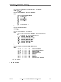
Source terms.
(srctab
(compflux
(comp comp )
(name compux-name )
(range " elem-range " " elem-range "
(table
comp-ux-table )
(enthalpy enthalpy-table )
)
<
<
>
<
<
>
> <
>
>
<
> :::)
:::
(compflux
)
:::
(phaseflux
(phase phase )
(name phaseux-name )
(range " elem-range " " elem-range "
(table
phase-ux-table )
(setcomp-internal)
(setcomp
( comp
(table conc-table )
<
<
<
<
<
)
>
>
>
<
>
<
>
> :::)
>
following only for thermal models
(enthalpy <enthalpy-table>)
:::
(<comp>
:::
)
)
)
:::
(phaseflux
)
:::
)
The parameters in compflux species a component mass ux (kg/s) into an element or
range of elements through a table of source uxes at specied points in time. Linear
interpolation is used for time intervals between the table values. Positive ux is ux into
an element; negative ux is out of an element. There may be several compflux sets.
The phaseflux parameters species a phase mass ux (kg/s) into an element or a range of
elements through a table of source uxes at specied points in time. Linear interpolation
is used for time intervals between the table values. Positive ux is ux into an element;
negative ux is out of an element. There may be several phaseflux sets. The user must
specify the component concentrations withing the phase stream. An alternate option is to
DRAFT
USNT-NUFT User's Manual (March 20, 1996)
43
6. INPUT DATA DOCUMENTATION
srctab
use the internally model computed concentrations of each element.
Either setcomp-internal or setcomp options are used, but not both.
Important: One should use (output : : : (forcetimes : : : )) (see NUFT User Manual) to
force the model to hit specied times to prevent the model from skipping past at times
when the ux table changes abruptly.
<comp>
name
Name of component (includes energy component).
<compux-name> name
Name of the component ux set. Used when referring to this set within
output options.
<elem-range>" pattern string
Source ux will be applied to those elements which matches any of the
pattern strings. See NUFT User Manual for explanation of pattern strings.
"
<comp-ux-table> list of reals
Table of component mass uxes of the form
<t0> <q0> <t1> <q1> : : :
where the time values are given by <t0>, <t1>, : : :, which are of data type
t-real and the mass ux at these times are <q0>, <q1>, : : :, which are of
data type real and are in units of kg/sec. Linear interpolation is used for
values between the time values. The last time must be greater than the end
time of the run.
<phase>
name
Name of the phase.
<phaseux-name> name
Name of the phase ux set. Used when refering to this set within output
options.
<phase-ux-table> list of reals
Table of mass uxes of the phase that are of the form
<t0> <q0> <t1> <q1> : : :
where the time values are given by <t0>, <t1>, : : :, which are of data type
t-real and the mass ux at these times are <q0>, <q1>, : : :, which are of
data type real and are in units of kg/sec. Linear interpolation is used for
values between the time values. The last time must be greater than the end
time of the run.
<conc-table>
DRAFT
list of reals
USNT-NUFT User's Manual (March 20, 1996)
44
6. INPUT DATA DOCUMENTATION
srctab
Table of mole fraction concentrations of the components withing the phase
stream. The table is of the form
<t0> <x0> <t1> <x1> : : :
where the time values are given by <t0>, <t1>, : : :, which are of data type
t-real and the concentrations are <x0>, <x1>, : : :, which are of data type
real. An alternative is to specify the component concentrations used for
the ux of applied to each respective element as that within the element
itself, which is done by using the setcomp-internal command instead of
setcomp.
<enthalpy-table> list of reals
Table of specic partial enthalpies of the component (J/kg). The table is
of the form
<t0> <h0> <t1> <h1> : : :
where the time values are given by <t0>, <t1>, : : :, which are of data type
t-real and the enthalpy at these times are <h0>, <h1>, : : :, which are of
data type real and have units of Joules/kg. Linear interpolation is used for
values between the time values. The last time must be greater than the end
time of the run.
setcomp-internal
Calculate component and energy uxes based on concentrations and enthalphies in the respective phase within the element instead of specifying
through a table of concentrations and enthalpies.
DRAFT
USNT-NUFT User's Manual (March 20, 1996)
45
6. INPUT DATA DOCUMENTATION
bctab
Boundary conditions.
(bctab
<bc-name>
(
(basephase
<phase>)
<elem-range>" "<elem-range>" : : : )
(range "
(tables
( variable
)
<
> <var-table>)
:::
(<variable> <var-table>)
following is optional
(factor
( comp
)
<
> <factor-table>)
:::
(<comp> <factor-table>)
)
:::
<bc-name>
(
(basephase
<phase>)
<elem-range>" "<elem-range>" : : : )
(range "
(clamped)
following is optional
(factor
( comp
)
<
> <factor-table>)
:::
(<comp> <factor-table>)
)
:::
<bc-name>
:::
(
)
)
Species boundary conditions. Boundary conditions are implemented by specifying values
of the primary variables on special elements as functions of time.
Specication of primary variables at the boundary elements is the same as when specifyDRAFT
USNT-NUFT User's Manual (March 20, 1996)
46
6. INPUT DATA DOCUMENTATION
bctab
ing initial conditions as in state. Thus, one uses negative concentrations as place holders
for unneeded concentrations; however, unlike state no warning messages are printed if a
concentration is set (i.e. non-negative) but is not necessary.
Important: One should use (output : : : (forcetimes : : : )) (see NUFT User Manual) to
force the model to hit specied times to prevent the model from skipping past at times
when the variable or factor table changes abruptly.
"
<elem-range>" string pattern
Those elements which matches any of the pattern strings will be elements
which will be used to specify the boundary condition. See NUFT User
Manual for explanation of pattern strings.
<variable>
<var-table>
<comp>
word
Primary variable (same as those in state).
Time dependent table of values of <variable> of the form
<t0> <val0> <t1> <val1> : : :
where the time values are given by <t0>, <t1>, : : :, which are of data type
t-real and the values of the variables are <val0>, <val1>, : : : are of data
type real. Linear interpolation is used for values between the time values.
The last time must be greater than the end time of the run.
word
Name of component in factor table (includes energy component). There
must be a table for each component.
<factor-table>
Specify factor multiplying the component uxes between the elements specied in range and other elements. Linear interpolation is used for values
between the time values. The last time must be greater than the end time
of the run. One use of this factor is to turn o or turn on uxes at dierent
times. The table is of the form
<t0> <fac0> <t1> <fac1> : : :
where the time values are given by <t0>, <t1>, : : :, which are of data type
t-real and the factors at these times are <fac0>, <fac1>, : : :, which are
of data type real. Linear interpolation is used for values between the time
values. The last time must be greater than the end time of the run.
Instead of applying a factor to component uxes one can apply a factor to
phase uxes (see NUFT Reference Manual).
(clamped)
Keeps the primary variables for these elements, as set in state, xed in
time.
DRAFT
USNT-NUFT User's Manual (March 20, 1996)
47
6. INPUT DATA DOCUMENTATION
output
Output options.
Valid element output variables for the usnt module are:
P
gas phase pressure (Pa).
S.<phase>
saturation of <phase>.
C.<comp>.<phase>
mole fraction of <comp> in <phase>.
X.<comp>.<phase>
mass fraction of <comp> in <phase>.
T
temperature ( C).
Vmag.<phase>
magnitude of pore velocity of a phase (m/s).
Vel.<phase>
x,y,z components of the pore velocity (m/s),
valid only for by-contour option. porosity porosity.
vis.<phase>
viscosity of a phase (Nt-s/m).
Pc.<phase>
capillary pressure of a phase (Pa).
kr.<phase>
relative permeability of a phase.
Kx, Ky, Kz
permeabilities (m2/s) (see genmsh for denitions).
log10Kx, log10Ky, log10Kz
logarithm base 10 of permeabilities (log10 (m2/s)) (see genmsh for de
porosity
porosity.
Psat
saturation pressure (valid only
for nonisothermal option with water as
one of the components).
RH
relative humidity w.r.t. an open system (valid only
for nonisothermal option with water as one
of the components).
Valid connection output variables are:
DRAFT
USNT-NUFT User's Manual (March 20, 1996)
48
6. INPUT DATA DOCUMENTATION
.<phase>
.<phase>
.<comp>
V
q
q
.<comp>.<phase>
q
.<comp>
qd
.<comp>.<phase>
qd
.<comp>
qa
.<comp>.<phase>
qa
qrad
qcond
Q phase
Q comp
.<
.<
>
>
.<comp>.<phase>
Qd.<comp>
Q
.<comp>.<phase>
Qd
.<comp> total advective mass ux of component (kg/s)
Qa
.<comp>.<phase>
Qa
Qrad
Qcond
DRAFT
output
pore velocity (m/s) in <phase>.
specic mass ux of phase (kg/s-m2).
specic mass ux of component (kg/s-m2)
in all phases; if <comp> is `energy', then
output specic energy ux (W/m2) in all
phases including solid phase.
specic mass ux of
component (kg/s-m2) in <phase>;
if <comp> is `energy', then output specic energy
ux (W/m2) in <phase>.
specic diusive mass ux of component (kg/s-m2)
in all phases; if <comp> is `energy', then output speci
diusive energy ux (W/m2) in all
phases including solid.
specic diusive mass ux of component (kg/s-m2)
in <phase>; if <comp> is `energy', then output
specic diusive energy ux (W/m2)
in <phase>.
specic advective mass ux of component (kg/s-m2)
in all phases; if <comp> is `energy', then output
specic diusive energy ux (W/m2) all phases includi
specic advective mass ux of component (kg/s-m2)
in <phase>; if <comp> is `energy', then output
specic diusive energy ux (W/m2) in <phase> inclu
specic radiative thermal ux (W/m2).
specic conducitive thermal ux (W/m2).
total mass ux of phase (kg/s).
total mass ux of component (kg/s)
in all phases; if <comp> is `energy', then output total
in all phases including solid.
total mass ux of component (kg/s) in <phase>;
if <comp> is `energy', then output total energy ux (W
total diusive mass ux of component (kg/s)
in all phases; if <comp> is `energy', then output
total diusive energy ux (W) in all
including solid.
total diusive mass ux of component (kg/s) in <phase
if <comp> is `energy', then output total diusive energ
in <phase>.
in all phases; if <comp> is `energy', then output
total diusive energy ux (W)
in all phases including solid.
total advective mass ux of component (kg/s)
in <phase>; if <comp> is `energy', then output
total diusive energy ux (W) in <phase>.
total radiative thermal ux (W).
total conducitive thermal ux (W).
USNT-NUFT User's Manual (March 20, 1996)
49
6. INPUT DATA DOCUMENTATION
output
(output
(field
(file-ext " out-ext ")
(format options )
(index-range ( i0
i1
<
<
)
(variables
(outtimes
>
>
< > < > <j0> <j1> <k0> <k1>)
:::
(<i0> <i1> <j0> <j1> <k0> <k1>)
<el-var0> <el-var1> : : : )
<t0> <t1> : : : )
)
(flux-field
(file-ext " out-ext ")
(format options )
(index-crange
( ( i0
j0
k0
<
<
>
>
< > < > < > <i1> <j1> <k1>)
:::
(<i0> <j0> <k0> <i1> <j1> <k1>)
)
(variables
(outtimes
<con-var0> <con-var1> : : : )
<t0> <t1> : : : )
)
(history
(file-ext " out-ext ")
(variable el-var )
(element " element-name ")
)
<
<
<
>
>
>
(flux-history
(file-ext " out-ext ")
(variable con-var )
(index-con i0
j0
)
<
>
<
>
< > < > <k0> <i1> <j1> <k1>)
(srcflux
(comp comp )
(file-ext " out-ext ")
(outtimes t0
t1
)
(cumulative)
optional
)
<
>
<
>
< > < > :::
(bcflux
(comp comp )
(file-ext " out-ext ")
(outtimes t0
t1
)
(cumulative)
optional
)
<
(forcetimes
(outtimes
)
DRAFT
>
<
>
< > < > :::
<t0> <t1> : : : )
USNT-NUFT User's Manual (March 20, 1996)
50
6. INPUT DATA DOCUMENTATION
output
(restart
(file-ext " out-ext ")
(outtimes t0
t1
)
<
>
< > < > : : :)
(extool
(file-ext " out-ext ")
(index-range ( i0
i1
(variables var0
var1
(outtimes t0
t1
)
)
<
>
< > < > <j0> <j1> <k0> <k1>) : : :
< >< > : : : )
< > < > :::
)
)
species what variables will be dumped to les and the output format. Any of the above
output options (field, flux-field, etc.) are optional or can be present any number of
times in any order including with regards to dierent variables. (See below regarding other
options and important notes.) Output options are:
field
flux-field
history
flux-history
srcflux
bcflux
forcetimes
restart
extool
<out-ext>
<options>
DRAFT
output variables of selected elements at specied times
output uxes between selected elements at specied times
output variables of selected elements at all times
output the uxes between selected elements at all times (not applicable to USNT model)
output component uxes for a ux specied in srctab
output component uxes owing out of a set of boundary elements specied by bctab
force the model to hit the times specied in outtimes
write out a restart record to a le that can be read in by restart option
write out data in extool format.
string
sux of output le (file-ext is optional). The prex of the output le
name will be made up of the prex set by the output-prefix parameter.
(The sux should be some mnemonic, e.g. the name of the variable being
outputted.) For example, if output-prefix is set to "runA"and file-ext
to ".C"then output will go to le "runA.C".
If the file-ext parameter is not present, then the output will be placed
into the main output le. Output for dierent output options can share the
same output le.
word
format of output. Can be any of following:
list or by-list output values at elements along with the element names (contsac format
by-set
list element values as a vector of the form [#n v1 v2 : : : vn]
by-x
list x coord. and value
by-y
list y coord. and value
by-z
list z coord. and value
by-ijk
list i,j,k index and value
by-xtable
format compatible with state
using by-xtable method, user needs to comment
out output header
by-ytable
format compatible with state
using by-ytable method, user needs to comment
out output header
USNT-NUFT User's Manual (March 20, 1996)
51
6. INPUT DATA DOCUMENTATION
by-ztable
tabular
contour
output
format compatible with state
using by-ztable method, user needs to comment
out output header
multi-column format
format readable by the nview program
for MS-DOS
<index-range> list of integers
range of elements specied by the i; j; k indices.
<comp>
word
component name.
<el-var> word
<el-var0>, <el-var1> list of words
list of element variables that will be outputted (model specic).
<con-var> word
<con-var0>, <el-var1> list of words
list of connection variables (e.g. uxes) that will be outputted (model
specic).
<outtimes>
list of t-reals
list of times at which output will be performed. Model will reduce the time
steps to meet these times.
<index-crange> list of lists of integers
species a list of connections. Comprised of a list of list of integers with
each list specifying a connection. Each list of integers is of the form
(<i0> <j0> <k0> <i1> <j1> <k1>)
and denotes the connection between element i =<i0>, j =<j0>, k =<k0>
and element i =<i1>, j =<j1>, k =<k1>. Positive ux denotes ux from
the rst element to the second.
<out-var-name> word
name of output variable to be outputted by history option (model specic).
"
<element-name>" string
name of element whose state, or primary, variable will be outputted.
<index-con>
<bc-name>
DRAFT
list of integers
species the single connection between the element (i =<i0>, j =<j0>,
k =<k0>) and the element (i =<i1>, j =<j1>, k =<k1>). Positive ux
denotes ux owing from the rst element to the second.
word
name of boundary condition used in bctab.
USNT-NUFT User's Manual (March 20, 1996)
52
6. INPUT DATA DOCUMENTATION
<src-name>
output
word
name of source term used in srctab.
(cumulative)
optional. If present, the cumulative ux is outputted. If not present, the
instantaneous ux is outputted. Note that cumulative uxes are reset to
zero at the beginning of a restart.
Notes:
1. Instead of (file-ext "<out-ext>") one can use (file "<le-name>") in order to
explicitly specify the output le.
2. (outtimes <t0> <t1> <t2> : : : ) can be replaced by either of:
a. (outtimes *) which means all times.
b.
(triggers
((wake
(cond
)
:::
((wake
(cond
)
<state-var>
<state-var>
(range "
(range "
<el-name>"
<el-name>"
"
"
<state-var>
<state-var>
(range "
(range "
<el-name>" : : : ) <op> <val>)
<el-name>" : : : ) <op> <val>)
<el-name>"
<el-name>"
"
"
<el-name>" : : : ) <op> <val>)
<el-name>" : : : ) <op> <val>)
)
which checks to see at every time step if any of the triggers goes o. A trigger
goes o i its wake condition <value> <op> <val> is true where <value> is
the value of the state variable <state-var> at the elements with names in the
range of any of the pattern strings "<el-name>" : : :. If the wake condition is
true, then the condition in the cond eld is checked; if true then the trigger goes
o and output occurs. Triggers can go o only once.
3. One can use (range "<element-range>": : : ) instead of index-range to specify elements
by the names where "<element-range>" is a pattern string.
4. Similarly, one can use (crange ("<element-range-0>" "<element-range-2>") : : : ) instead of (index-crange ((<i0> <j0> <k0> <i1> <j1> <k1>) : : : )) to specify ranges
of elements. Here, ("<element-range-0>" "<element-range-1>") species all possible
connections between elements whose names match the pattern string "<element-range0>" and the elements whose names match "<element-range-1>".
5. One can use (connection "<element-name-0>" "<element-name-1>") instead of (index-con
<i0> <j0> <k0> <i1> <j1> <k1>) to specify a connection.
DRAFT
USNT-NUFT User's Manual (March 20, 1996)
53
6. INPUT DATA DOCUMENTATION
vapor-pressure-lowering
Vapor pressure lowering option.
the model implements vapor pressure lowering. the default is on. to turn o vapor pressure
lowering add the following to the topmost input level:
(vapor-pressure-lowering off)
DRAFT
USNT-NUFT User's Manual (March 20, 1996)
54
6. INPUT DATA DOCUMENTATION
Notes: Table Time Values
6.1. Notes: Table Time Values
Currently, the model may in some cases choose time steps which are so large that it overshoots
sharp changes in a time table. This may be a serious problem if, for example, we want to model
a ux that is turned o suddenly. A solution is to use the forcetimes command in output
which forces the model to hit specied times, in this case, the times at which the boundary
condition changes suddenly.
The last time value in table must be greater than or equal to the ending time of the simulation as set by tstop or the model will abort.
DRAFT
USNT-NUFT User's Manual (March 20, 1996)
55
REFERENCES
7. References
Lee, K., A. Kulshrestha, and J. Nitao, Interim Report on Verication and Benchmark Testing
of the NUFT Computer Code, Lawrence Livermore National Laboratory Report UCRLID-113521, 1993.
Nitao, J.J., Reference manual for the NUFT ow and transport code, Lawrence Livermore
National Laboratory Report, UCRL-ID-113520, 1995.
DRAFT
USNT-NUFT User's Manual (March 20, 1996)
56
APPENDIX A{ SAMPLE PROBLEM NO. 1
A. Sample Problem No. 1: Isothermal
Description:
Two-dimensional isothermal inltration problem in a cylindrically symmetric system with \point"
constant head source of water. Three soil types. The source is turned o after 200 minutes. A
conservative tracer is introduced along with the water.
Input le:
;;;file: usnsam1.in;;;
;; sample problem
(usnt ;; name of flow model
(modelname flow)
(title "usnt sample #1")
(tstop 23.1h)
(stepmax 1000)
(time 0.0)
(dtmax 1.e30)
(dt 1m )
;;
;;
;;
;;
;;
;; run title
stopping time is 23.1 hours
maximum no. of time steps
initial time
maximum time step
initial time step is 1 minute
(init-eqts
(components water air contam)
(phases liquid gas)
(primary-phase gas)
(wetting-phase liquid)
(isothermal)
)
(input-mass-fraction off)
;; use mole fraction C instead of mass fraction
;;;; uncomment following lines for preconditioned conjugate gradient
;;;; method:
;;
(linear-solver pcg)
;;
(pcg-parameters (precond d4) (north 15) (toler 1.e-5)
;;
(itermax 100))
;;
(ilu-degree 1)
;; set output formats
(output
;; outputs all liquid saturation into file "usnsam1.Sl"
(field (format list) (range "*") (variables S.liquid)(file-ext ".Sl")
(outtimes 0 39m 70m 102m 222m 287m 342m 23h)
)
;; outputs aqueous phase concentration of contaminant
;; into file "usntsam1.Con"
(field (format list) (range "*")
(variables C.contam.liquid)
(file-ext ".Con")
(outtimes 0 39m 70m 102m 222m 287m 342m 23h)
)
;; outputs all pressure into file "usntsam1.P"
(field (format list) (range "*") (variables P)(file-ext ".P")
(outtimes 0 39m 70m 102m 222m 287m 342m 23h)
DRAFT
USNT-NUFT User's Manual (March 20, 1996)
57
APPENDIX A{ SAMPLE PROBLEM NO. 1
)
;; output liquid phase flux from source into file "usntsam1.inf"
(bcflux (comp water) (name src) (file-ext ".inf")
(outtimes *))
;; force model to hit specific times when source is shut off
(forcetimes (outtimes 200m 201m)
)
) ;; end output
;; set material properties
(rocktab
;; sandy material
(HI
(porosity 0.25)
(Kd
(contam 0.0) ;; conservative tracer
(air 0.0)
(water 0.0))
(Kx 1.53e-12)(Ky 0.)(Kz 0.)
(pc (liquid pcVanGen (m 0.6)(alpha 5.1e-4)(Sj 0.41)(Sr 0.4)))
(kr (gas krgVanGen (m 0.6)(Sr 0.05))
(liquid krlVanGen (m 0.6)(Sr 0.4)))
(tort (liquid Millington (Sr 0.4)) (gas Millington (Sr 0.05)))
)
;; moderate permeability material
(MOD
(porosity 0.3)
(Kd
(contam 0.0) ;; conservative tracer
(air 0.0)
(water 0.0))
(Kx 1.53e-13)(Ky 0.)(Kz 0.)
(pc (liquid pcVanGen (m 0.3)(alpha 1.0e-4)(Sj 0.41)(Sr 0.4)))
(kr (gas krgVanGen (m 0.3)(Sr 0.05))
(liquid krlVanGen (m 0.3)(Sr 0.4)))
(tort (liquid Millington (Sr 0.4))(gas Millington (Sr 0.05)))
)
;; clayey material
(LO
(porosity 0.3)
(Kd
(contam 0.0) ;; conservative tracer
(air 0.0)
(water 0.0))
(Kx 1.5e-14)(Ky 0.)(Kz 0.)
(pc (liquid
pcVanGen (m 0.2)(alpha 5.1e-5)(Sj 0.41)
(Sr 0.4)))
(kr (gas krgVanGen (m 0.2)(Sr 0.05))
(liquid krlVanGen (m 0.2)(Sr 0.4)))
(tort (liquid Millington (Sr 0.4))(gas Millington (Sr 0.05)))
)
;; pseudo soil type for source element above surface
(SRC
(porosity 0.99)
(Kd
(contam 0.0) ;; conservative tracer
DRAFT
USNT-NUFT User's Manual (March 20, 1996)
58
APPENDIX A{ SAMPLE PROBLEM NO. 1
(air 0.0)
(water 0.0))
(Kx 1.e-9)(Ky 0.)(Kz 0.)
(pc (liquid
0.0)) ;; zero cap. pressure
(kr (gas 0.0)(liquid 1.0)) ;; gas rel. perm. set to zero
;; liquid rel. perm. set to unity
(tort (liquid 0.0)(gas 0.0)) ;; turn off all diffusive fluxes
)
;; pseudo soil type for inactive elements (no. perm.) above surface
(INACT (porosity 0.99)
(Kd
(contam 0.0) ;; conservative tracer
(air 0.0)
(water 0.0))
(Kx 0.)(Ky 0.)(Kz 0.)
(pc (liquid
0.0))
(kr (gas 0.0)(liquid 0.0))
(tort (liquid 0.0)(gas 0.0))
)
) ;; end rocktab
;; phase properties
(phaseprop
(liquid
(rhoP rhoPLiqWat)
(viscosity visLiqWat)
)
(gas
(rhoP rhoPZFacStm)
(viscosity visGasAirWat)
)
) ;; end phaseprop
;; component properties
(compprop
(water
(intrinsic (MoleWt 18.))
(gas
(Keq KeqWatVapor)
(freeDiffusivity 1.e-4))
(liquid (freeDiffusivity 1.e-9)
(Keq 1.0)
(rhoC rhoCLiqWat))
)
(air
(intrinsic (MoleWt 29.))
(gas
(Keq KeqStd (C 0.973e11)(D 0.0))
(freeDiffusivity 1.e-4))
(liquid (freeDiffusivity 1.e-9)
(Keq 1.0))
)
(contam ;; contaminant
(intrinsic (MoleWt 130.))
DRAFT
USNT-NUFT User's Manual (March 20, 1996)
59
APPENDIX A{ SAMPLE PROBLEM NO. 1
(gas
(Keq KeqTCESolute)
(freeDiffusivity 1.e-4))
(liquid (freeDiffusivity 1.e-9) (Keq 1.0)
(rhoC rhoCLiqWat))
)
);;end component properties
(generic
(T 15.)
)
;; temperature in degrees C
;; set boundary conditions
(bctab
;; put flux into the source element
(src
(range "S*")
(basephase liquid)
;; turn source on from 0 to 200 min. and off after that
(factor (water 0.0 1.0 200m 1.0 201m 0.0 1.e30 0.0)
(contam 0.0 1.0 200m 1.0 201m 0.0 1.e30 0.0)
(air 0.0 1.0 200m 1.0 201m 0.0 1.e30 0.0)
)
;; set element to constant head of 3.5 meters
(tables
(S.liquid 0. 1.0 1.e30 1.0)
(P
0. 1.34e5 1.e30 1.34e5)
(C.contam
0. 0.001 1.e30 0.001)
(C.air 0. 1.e-6 1.e30 1.e-6)
)
)
)
;; keep water table elements at saturated conditions
(WT
(range "W*")
(basephase liquid)
(tables
(S.liquid 0. 0.95 1.e30 0.95)
(P
0. 1.e5 1.e30 1.e5)
(C.contam
0. 0.0 1.e30 0.0)
(C.air 0. 1.e-6 1.e30 1.e-6)
)
)
;; end bctab
;; initial conditions
(state
(S.liquid
by-key ("S*" 1.0 ) ("I*" 1.0) ("H*" 0.2) ("M*" 0.3) ("L*" 0.8)
("W*" 0.95)
)
(C.contam by-key ("*" 0.0))
(C.air
by-key ("S*" 1.e-6) ("I*" 1.e-6) ("H*" -1.) ("M*" -1.)
("L*" -1.)
("W*" 1.e-6)
DRAFT
USNT-NUFT User's Manual (March 20, 1996)
60
APPENDIX A{ SAMPLE PROBLEM NO. 1
)
(P
by-key
("*"
1.e5))
;; note that bctab will overwrite
;; these values by any set there
) ;; end state
;; generate mesh
(genmsh
(coord cylind)
;; note that increasing z coordinate will be downward
(down 0. 0. 1.)
;; set subdivisions in radial r direction
(dx
0.05 ;; 0.05 radius source
0.1
;; r = 0.15
0.2
;; r = 0.35
0.4
;; r = 0.75
0.5
;; r = 1.25
0.5
0.5
0.5
;; note: nr = 8
)
;; set angle subdivision
(dy 360.)
;; set subdivisions in z direction
(dz
0.01 ;; set first row of elements which are inactive
;; except for i=1 for surface flux
1.0
;; sandy material layer
1.0
;; moderate material layer
1.0
;; sandy material layer
1.0
;; clay material layer
1.0
;; sandy material layer
0.01 ;; water table k=7
)
;; set material type and element name prefix
(mat
(S SRC
1 1 1 1 1 1)
;; source element
(I INACT 2 8 1 1 1 1)
;; inactive elements
(H HI
1 8 1 1 2 2)
;; sandy layer
(M MOD
1 8 1 1 3 3)
;; moderate perm
(H HI
1 8 1 1 4 4)
;; sandy
(L LO
1 8 1 1 5 5)
;; clay
(H HI
1 8 1 1 6 6)
;; sandy
(W HI
1 8 1 1 7 7)
;; water table elements
)
) ;; end genmsh
) ;;; end of input
DRAFT
USNT-NUFT User's Manual (March 20, 1996)
61
APPENDIX B{ SAMPLE PROBLEM NO. 2
B. Sample Problem No. 2: Thermal
Description:
Same problem as Problem No. 1 but non-isothermal. The ground condition is kept xed at 25
degrees C while the subsurface is initialized at 15 degrees C. The saturated zone at the bottom
of the model is kept xed at 15 degrees C. Another dierence is that the topmost elements are
no longer inactive elements but are modied to serve to simulate xed atmospheric conditions.
Input le:
;; file: usnsam2.in;;;
;; sample problem
(usnt ;; name of flow model
(modelname flow)
(title "usnt sample #2")
(tstop 23.1h)
(stepmax 1000)
(time 0.0)
(dtmax 1.e30)
(dt 1m )
;;
;;
;;
;;
;;
;; run title
stopping time is 23.1 hours
maximum no. of time steps
initial time
maximum time step
initial time step is 1 minute
;; absolute time step tolerance
(tolerdt (P 1.e5)(S 0.25)(C 0.1)(C.contam 1.e-4)(T 15.0))
;; relative time step tolerance
(reltolerdt (P 0.2)(S 0.0)(C 0.1)(T 0.1))
;; absolute NR conv. tolerance
(tolerconv (P 100.)(S 1.e-3)(C 1.e-3)(C.contam 1.e-5)(T 0.001))
;; absolute NR conv. tolerance
(reltolerconv (P 1.e-3)(S 0.0)(C 1.e-4)(T 1.e-4))
(init-eqts
(components water air contam)
(phases liquid gas)
(primary-phase gas)
(wetting-phase liquid)
(thermal)
)
(input-mass-fraction off)
;; use mole fraction C instead of mass fraction
;;;; uncomment following lines for preconditioned conjugate gradient
;;;; method:
;;
(linear-solver pcg)
;;
(pcg-parameters (precond d4) (north 15) (toler 1.e-5)
;;
(itermax 100))
;;
(ilu-degree 1)
;; set output formats
(output
;; outputs all liquid saturation into file "usnsam2.Sl"
(field (format list) (range "*") (variables S.liquid)(file-ext ".Sl")
(outtimes 0 39m 70m 102m 222m 287m 342m 23h)
)
DRAFT
USNT-NUFT User's Manual (March 20, 1996)
62
APPENDIX B{ SAMPLE PROBLEM NO. 2
;; outputs temperature into file "usnsam2.T"
(field (format list) (range "*") (variables T)(file-ext ".T")
(outtimes 0 39m 70m 102m 222m 287m 342m 23h)
)
;; outputs aqueous phase concentration of contaminant
;; into file "usnsam2.Con"
(field (format list) (range "*")
(variables C.contam.liquid)
(file-ext ".Con")
(outtimes 0 39m 70m 102m 222m 287m 342m 23h)
)
;; outputs all pressure into file "usnsam2.P"
(field (format list) (range "*") (variables P)(file-ext ".P")
(outtimes 0 39m 70m 102m 222m 287m 342m 23h)
)
;; output liquid phase flux from source into file "usnsam2.inf"
(bcflux (comp water) (name src) (file-ext ".inf")
(outtimes *))
;; force model to hit specific times when source is shut off
(forcetimes (outtimes 200m 201m)
)
) ;; end output
;; set material properties
(rocktab
;; sandy material
(HI
(porosity 0.25)
(Kd
(contam 0.0) ;; conservative tracer
(air 0.0)
(water 0.0))
(KdFactor (water 1.0)(air 1.0)(contam 1.0))
(Cp 840)(solid-density 2580)
(tcond tcondSqrt (solid 1.74)(liquid 2.34)(gas
(Kx 1.53e-12)(Ky 0.)(Kz 0.)
(pc (liquid pcVanGen (m 0.6)(alpha 5.1e-4)(Sj
(Sr 0.4)))
(kr (gas krgVanGen (m 0.6)(Sr 0.05))
(liquid krlVanGen (m 0.6)(Sr 0.4)))
(tort (liquid Millington (Sr 0.4))
(gas Millington (Sr 0.05)))
)
;; moderate permeability material
(MOD
(porosity 0.3)
(Kd
(contam 0.0) ;; conservative tracer
(air 0.0)
(water 0.0))
(KdFactor (water 1.0)(air 1.0)(contam 1.0))
(Cp 840)(solid-density 2580)
(tcond tcondSqrt (solid 1.74)(liquid 2.34)(gas
(Kx 1.53e-13)(Ky 0.)(Kz 0.)
(pc (liquid pcVanGen (m 0.3)(alpha 1.0e-4)(Sj
DRAFT
USNT-NUFT User's Manual (March 20, 1996)
1.74))
0.41)
1.74))
0.41)
63
APPENDIX B{ SAMPLE PROBLEM NO. 2
(Sr 0.4)))
(kr (gas krgVanGen (m 0.3)(Sr 0.05))
(liquid krlVanGen (m 0.3)(Sr 0.4)))
(tort (liquid Millington (Sr 0.4))
(gas Millington (Sr 0.05)))
)
;; clayey material
(LO
(porosity 0.3)
(Kd
(contam 0.0) ;; conservative tracer
(air 0.0)
(water 0.0))
(KdFactor (water 1.0)(air 1.0)(contam 1.0))
(Cp 840)(solid-density 2580)
(tcond tcondSqrt (solid 1.74)(liquid 2.34)(gas 1.74))
(Kx 1.5e-14)(Ky 0.)(Kz 0.)
(pc (liquid
pcVanGen (m 0.2)(alpha 5.1e-5)(Sj 0.41)
(Sr 0.4)))
(kr (gas krgVanGen (m 0.2)(Sr 0.05))
(liquid krlVanGen (m 0.2)(Sr 0.4)))
(tort (liquid Millington (Sr 0.4))
(gas Millington (Sr 0.05)))
)
;; pseudo soil type for source element above surface
(SRC
(porosity 0.99)
(Kd
(contam 0.0) ;; conservative tracer
(air 0.0)
(water 0.0))
(KdFactor (water 1.0)(air 1.0)(contam 1.0))
(Cp 840)(solid-density 2580)
(tcond tcondSqrt (solid 1.74)(liquid 2.34)(gas 1.74))
(Kx 1.e-9)(Ky 0.)(Kz 0.)
(pc (liquid
0.0)) ;; zero cap. pressure
(kr (gas 0.0)
;; gas rel. perm. set to zero
(liquid 1.0)) ;; liquid rel. perm. set to unity
(tort (liquid 0.0);; turn off all diffusive fluxes
(gas 0.0))
)
;; pseudo soil type for atmosphere above ground surface
(ATM (porosity 0.99)
(Kd
(contam 0.0) ;; conservative tracer
(air 0.0)
(water 0.0))
(KdFactor (water 1.0)(air 1.0)(contam 1.0))
(Cp 840)(solid-density 2580)
(tcond tcondSqrt (solid 1.74)(liquid 2.34)(gas 1.74))
(Kx 0.)(Ky 0.)(Kz 0.)
(pc (liquid
0.0))
(kr (gas krLinear (Sr 0.0)) (liquid 1.0))
(tort (liquid 0.0) (gas 1.0))
)
DRAFT
USNT-NUFT User's Manual (March 20, 1996)
64
APPENDIX B{ SAMPLE PROBLEM NO. 2
) ;; end rocktab
;; phase properties
(phaseprop
(liquid
(rhoP rhoPLiqWat)
(viscosity visLiqWat)
(enthP enthPLinearMix)
(pcTemFac watPcTemFac)
)
(gas
(rhoP rhoPZFacStm)
(viscosity visGasAirWat)
(enthP enthPLinearMix)
)
) ;; end phaseprop
;; component properties
(compprop
(water
(intrinsic (MoleWt 18.))
(gas
(Keq KeqWatVapor)
(freeDiffusivity 1.e-4)
(enthC enthCWatVap))
(liquid (freeDiffusivity 1.e-9) (Keq 1.0)
(enthC enthCLiqWat)
(rhoC rhoCLiqWat))
)
(air
(intrinsic (MoleWt 29.))
(gas (Keq KeqStd (C 0.973e11)(D 0.0))
(freeDiffusivity 1.e-4)
(enthC enthCConstCp (Cp 1009.0)(Tref 0.0) (Hv 0.0)) )
(liquid (freeDiffusivity 1.e-9)
(Keq 1.0) (enthC 0.0) )
)
(contam ;; contaminant
(intrinsic (MoleWt 130.))
(gas
(Keq KeqTCESolute)
(freeDiffusivity 1.e-4) (enthC 0.0))
(liquid (freeDiffusivity 1.e-9) (Keq 1.0)
(rhoC rhoCLiqWat)
(enthC 0.0))
)
);;end component properties
;; set boundary conditions
(bctab
;; put flux into the source element
(src
(range "S*")
(basephase liquid)
DRAFT
USNT-NUFT User's Manual (March 20, 1996)
65
APPENDIX B{ SAMPLE PROBLEM NO. 2
;; turn source on from 0 to 200 min. and off after that
(factor (water 0.0 1.0 200m 1.0 201m 0.0 1.e30 0.0)
(contam 0.0 1.0 200m 1.0 201m 0.0 1.e30 0.0)
(air 0.0 1.0 200m 1.0 201m 0.0 1.e30 0.0)
(energy 0.0 1.0 200m 1.0 201m 0.0 1.e30 0.0)
)
;; set element to constant head of 3.5 meters
(tables
(S.liquid 0. 1.0 1.e30 1.0)
(P
0. 1.34e5 1.e30 1.34e5)
(C.contam
0. 0.001 1.e30 0.001)
(C.air 0. 1.e-6 1.e30 1.e-6)
(T 0. 15. 1.e30 15.)
)
)
;; keep water table elements at saturated conditions
(WT
(range "W*")
(basephase liquid)
;; instead of tables we could have used (clamped) option
(tables
(S.liquid 0. 1.0 1.e30 1.0)
(P
0. 1.e5 1.e30 1.e5)
(C.contam
0. 0.0 1.e30 0.0)
(C.air 0. 1.e-6 1.e30 1.e-6)
(T 0. 15. 1.e30 15.)
)
)
;; fix conditions at atmosphere elements
(atmos (range "A*") (clamped))
)
;; end bctab
;; initial conditions
(state
(S.liquid
by-key ("S*" 1.0 ) ("A*" 0.0) ("H*" 0.2) ("M*" 0.3) ("L*" 0.8)
("W*" 1.0)
)
(C.contam by-key ("*" 0.0))
(C.air
by-key ("S*" 1.e-6) ("A*" 0.99) ("H*" -1.) ("M*" -1.)
("L*" -1.)
("W*" 1.e-6)
)
(P by-key
("*"
1.e5)) ;; note that bctab will overwrite
;; these values by any set there
(T by-key ("*" 15.)("A*" 25.))
) ;; end state
;; generate mesh
(genmsh
(coord cylind)
DRAFT
USNT-NUFT User's Manual (March 20, 1996)
66
APPENDIX B{ SAMPLE PROBLEM NO. 2
;; note that increasing z coordinate will be downward
(down 0. 0. 1.)
;; set subdivisions in radial r direction
(dx
0.05 ;; 0.05 radius source
0.1
;; r = 0.15
0.2
;; r = 0.35
0.4
;; r = 0.75
0.5
;; r = 1.25
0.5
0.5
0.5
;; note: nr = 8
)
;; set angle subdivision
(dy 360.)
;; set subdivisions in z direction
(dz
0.01 ;; set first row of elements which are inactive
;; except for i=1 for surface flux
1.0
;; sandy material layer
1.0
;; moderate material layer
1.0
;; sandy material layer
1.0
;; clay material layer
1.0
;; sandy material layer
0.01 ;; water table k=7
)
;; set material type and element name prefix
(mat
(S SRC
1 1 1 1 1 1)
;; source element
(A ATM
2 8 1 1 1 1)
;; atmosphere elements
(H HI
1 8 1 1 2 2)
;; sandy layer
(M MOD
1 8 1 1 3 3)
;; moderate perm
(H HI
1 8 1 1 4 4)
;; sandy
(L LO
1 8 1 1 5 5)
;; clay
(H HI
1 8 1 1 6 6)
;; sandy
(W HI
1 8 1 1 7 7)
;; water table elements
)
) ;; end genmsh
) ;;; end of input
DRAFT
USNT-NUFT User's Manual (March 20, 1996)
67
APPENDIX C{ THE MATHEMATICAL MODEL
C. The Mathematical Model
We give the balance equations solved by the USNT model. Suppose we have NC number of
components and NP number of phases. The solid phase is assumed nondeformable. The mass
balance equations for the = 1; : : :; NC components are
@ X S ! = X r S (! V + J + J ) X S !
(1)
h
@t where Fickian laws for dispersive and diusive uxes are given by
Jh = Dhr!
(2)
J = D r!
(3)
and Darcy's law gives
S V = k(S ) (rp + grz)
(4)
The retention pressure (\capillary pressure") relationships are given by
p = pg pc(S ); 6= g:
(5)
The various
variables are dened as
! mass fraction of -component in phase S liquid saturation of -phase
porosity
mass phase density
! mass fraction
decay constant ( = ln(2)=half life
V liquid phase velocity
Jh hydrodynamic dispersive ux
J molecular diusive ux
Dh dispersion tensor
D diusion coecient
k permeability function
liquid phase viscosity
p
phase pressure
pc retention pressure function
The hydrodynamic dispersion ux, Jh , is not currently implemented in the model. In addition to the balance equations we have the constraints
X ! = 1
(6)
X
S = 1:
(7)
The model assumes local thermodynamic equilibrium and partitioning of components between
phases are expressed in terms of partitioning coecients,
n :
n = K;
(8)
where K; is a function of pressure and temperature. The variables n and n are the mole
fractions of the -component in the and phases. They are related to the mass fractions by
0
1
X
n = (! =M ) = @ ! =M A :
(9)
USNT-NUFT User's Manual (March 20, 1996)
68
( )
DRAFT
APPENDIX C{ THE MATHEMATICAL MODEL
The balance equation for energy is
"
#
@ X u S + (1 ) C (T T ) =
s p
ref
@t XX
[rh S (! V + Jh + J )] + rKH rT
(10)
where
T
temperature
Cp specic heat of solid
s solid density
u specic internal energy
h partial specic enthalpy
KH thermal conductivity.
Mixing laws are used to compute phase quantities from component quantities. Currently available ones are as follows
1 = X !
(11)
h =
X
! h
(12)
Currently, phase viscosities correlation are available for pure water in the liquid phase and waterair mixture for the gas phase. Constant phase viscosity values may also be used. Future plans
include various mixing laws and viscosity correlations.
The balance equations are discretized in space using the integrated nite dierence method, and
discretized in time using the fully implicity backward Euler method. The resulting nonlinear
system of NC+1 equations are solved at each time step using the Newton Raphson method (see
NUFT Reference Manual).
DRAFT
USNT-NUFT User's Manual (March 20, 1996)
69