1
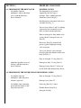
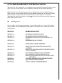
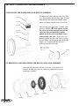
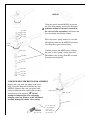
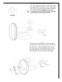
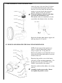
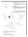
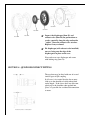
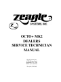
OCTO+ MK2
DEALERS
SERVICE TECHNICIAN
MANUAL
Zeagle Systems, Inc.
37150 Chancey Road
Zephyrhills, FL 33541
Phone (813) 782-5568
Fax (813) 782-5569
SECTION 1
PROBLEM DIAGNOSIS
1.1 PROBLEMS IN THE REGULATOR
Air bubbles from the
mouthpiece and/or exhalation
valve (with the buoyancy
device deflated).
POSSIBLE CAUSES
The intermediate air pressure
supplied by the first stage is
too high. (Max. working pressure
should not exceed 160 psi.)
Insufficient free movement in the lever
assembly (See Fig. 1.)
Valve or lever (Items 3 and 23) sticking.
(Operate the lever manually several
times to check smooth operation).
Worn or damaged or dirty rubber valve
seating (Item 9) damaged valve seat
(Item 6).
End cover (Item 22) distorted and
presses against diaphragm causing
valve to operate.
Valve seat (Item 6) is not correctly
located against the shoulder in the valve
body (See Fig. 3).
Dirty or damaged ‘O’ ring (Item 14).
Additional possible causes of
leakage (with the buoyancy
device inflated).
Damaged or dirty ‘O’ ring (Item 5).
Damaged casing (Item 17) allows air
to leak back from the buoyancy device.
1.2 PROBLEMS IN THE POWER INFLATOR POSSIBLE CAUSES
Air bubbles from the
mouthpiece when the power
inflator is operated.
Dirty or damaged ‘O’ ring (Item 5).
Air bubbles from around the
power inflator button or lock
ring when operated.
Lock ring (Item 28) is loose.
Damaged case (Item 17).
Flexible button (Item 29) is
damaged or faulty.
OCTO+ MK2 DEALERS SERVICE TECHNICIAN MANUAL
This manual has been compiled to assist authorized service personnel to diagnose problems, make
repairs and carry out the periodic service required to maintain safe and reliable functioning.
This manual does not substitute for proper factory training in the service of Zeagle regulators.
Before carrying out any work on the regulator you should study the notes and diagrams carefully,
and ensure that a suitable clean work area and all necessary tools and parts are available.
Throughout this manual the following symbol ☛ has been used to denote particularly important
points, often related to safety.
☛
Most Important!
You are dealing with life support equipment. A responsible attitude to all aspects of the maintenance procedure and careful handling of the product is essential to safety—both your own and
your customer’s.
SECTION 1
PROBLEM DIAGNOSIS
SECTION 1.1
SECTION 1.2
SECTION 1.3
SECTION 1.4
PROBLEMS IN THE REGULATOR
PROBLEMS IN THE POWER INFLATOR
PROBLEMS IN THE ORAL INFLATOR/EXHAUST
VALVE
PROBLEMS IN QD COUPLING
SECTION 2
DISMANTLE AND RE-ASSEMBLE
SECTION 2.1
REMOVING THE POWER INFLATOR BUTTON
ASSEMBLY
REMOVING AND DISMANTLING THE REGULATOR
VALVE ASSEMBLY
RE-BUILDING THE REGULATOR ASSEMBLY
RE-ASSEMBLING THE POWER INFLATOR
REMOVE AND DISMANTLE THE ORAL INFLATOR/
DEFLATOR
TESTING AND ADJUSTING THE REGULATOR
QUICK DISCONNECT FITTING
ANNUAL SERVICE REQUIREMENTS
SECTION 2.2
SECTION 2.3
SECTION 2.4
SECTION 2.5
SECTION 3
SECTION 4
SECTION 5
SECTION 2 - DISMANTLE AND REASSEMBLE
2.1 REMOVING THE POWER INFLATOR BUTTON ASSEMBLY
To remove the power inflator valve core (Item
31). First unscrew the lock ring (Item 28 righthand thread) and remove the flexible rubber
button and button support (Items 29 and 30).
Item #28
Item #29
Item #30
Unscrew the valve core using a suitable valve
core key APTP29. ☛ If the rubber seal on
the valve core is not removed intact on the
valve core, the seal should be carefully
picked out of the valve body (Item 2) and
replaced with valve core. If the seal is accidentally pushed into the valve body it can usually be shaken out through the bore of the QD
nipple. It is essential that the old seal is
removed from the valve body.
Item #31
Valve Core
Seal
Make sure “Rubber
Seal” is not left in
valve core.
Item# 2
2.2 REMOVING AND DISMANTLING THE REGULATOR VALVE ASSEMBLY
After removing the power inflator valve core as described in 2.1,
unscrew the lock ring (Item 18) and remove the front cover and
diaphragm assembly.
Item #17
Item #19
Item #21
Item #20
Item #22
Item #18
Power inflator button is stiff
to operate.
The valve core (Item 31) is faulty.
Buoyancy device inflates
slowly or rapidly without
operating the power inflator.
The valve core (Item 31) is
not securely screwed into the
valve body (See Fig. 5).
The valve core (Item 31) is faulty.
1.3 PROBLEMS IN THE ORAL
INFLATOR/EXHAUST VALVE
POSSIBLE CAUSES
Air leaks from the joint between the
regulator and oral inflator bodies.
Dirty or damaged ‘O’ ring (Item 13).
Air leaks from the oral inflator orifice.
Dirty or damaged seating (Item 34).
Damaged seat in body (Item 11).
Air leaks from around oral
inflator button.
Dirty or damaged ‘O’ ring (Item 13).
1.4 PROBLEMS IN THE QD COUPLING
(See Fig. 4)
Coupling is difficult to or will not lock
onto the connecting nipple.
Coupling disconnects from nipple in
use.
Coupling is difficult to disconnect
from nipple.
POSSIBLE CAUSES
Problems with the QD coupling are
almost invariably due to dirt or
build-up of deposits in or around the
locking balls and sleeve. Thorough
rinsing or soaking the coupling in
warm water followed by a light
application of a water displacing
lubricant normally cures these problems.
Coupling fails to self seal when
disconnected. (See above).
Dirty or damaged ‘O’ ring in coupling
Coupling leaks when connected
to the nipple.
Damaged nipple.
APSO10
Using the special wrench APS010 to prevent
the valve from turning, unscrew the nyloc nut
☛ (take note of how far the nut is screwed on
the valve to assist reassembly) and remove the
lever and nylon anti-friction washers.
Item #24
Item #25
Item #23
Item #25
The valve stem is spring loaded, so cover the
QD opening and leave the ASP010 tool inserted to keep these parts from escaping.
Item #5
O-Ring
Item #2
Carefully remove the APS010 tool, catching
the parts as they “spring” out the open end.
The rubber valve seating (Item #9) can now
be removed and replaced.
Item #15
Item #3
Item #9
Item #6
Item #14
O-Ring
2.3 RE-BUILDING THE REGULATOR ASSEMBLY
Replace the valve stem and spring in the valve
body. Using the blunt end of the core key tool
APTP29, compress the valve and spring sufficiently to allow the lever, anti-friction washers
and nyloc nut to be replaced. ☛ Do not
attempt to compress the valve and spring
using the valve seat (Item 6) as this will almost
certainly damage the rubber valve seating.
O-Ring #5
Item #2
Item #3
APTP29
Valve Core Key
Use the blunt end
of tool APTP29 to
compress the
valve and spring
into (Item #2).
☛
The valve body (Item 2) and the casing (Item 17)
have corresponding location flats to prevent possible
movement of the valve body in service. The ridge in
the casing is not strong enough to prevent turning of
the valve body when tightening the QD nipple.
A special service tool APTP28 must be used otherwise damage to the casing is possible.
APTP28
Item #8
Using the service tool APTP28, put into position to
prevent the valve body turning, unscrew the QD nipple about 3/16". When the nipple is loose, remove
the service tool and use the partially unscrewed nipple to help push the valve body out of the casing,
then proceed to unscrew and remove QD nipple.
Item #8
O-Ring #10
Valve Body
Section
2.4 RE-ASSEMBLING THE POWER INFLATOR
Item# 28
☛
Item# 29
Item# 30
Always fit a new valve core (Item 31) if there
is any doubt about the integrity of this item.
Press the valve core firmly into the body while
turning it to ensure that the thread engages
properly, tighten securely into position.
Do not over-tighten as this may cause damage to the core mechanism or seal.
The shoulder of the core should be level with
or just below the diameter of the valve body.
0.03” MAX
Item# 31
Seal
Fig. 5
Seal
Replace the flexible rubber button, support and
lock ring (Items 28, 29 and 30)
2.5 REMOVE AND DISMANTLE THE ORAL INFLATOR/DEFLATOR
NOTE: Do not separate the regulator case
(Item 17) and oral inflator body (Item 11)
except to replace the ‘O’ ring (Item 13).
Remove the posidrive screw behind the lever to
release the oral inflator body which can now be
slid off its dove tail.
Item# 27
Item# 26
Item# 11
Item# 35
Removing the posidrive screw in the button
will release all the remaining components. Use
the fork end of the special OCTO+ wrench,
APS010, to prevent the valve turning.
Item# 34
Item# 13
O-Ring
☛
Item# 32
Item# 33
Item# 16
Check the condition of the rubber valve seating
and seat.
Assembly is in the reverse order. Do not
over-tighten the posidrive screws.
Remember approximately how far to screw on the
nyloc nut to the stem.
Using the special OCTO+ wrench to prevent the
valve turning, replace the nyloc nut to approximately
the same position prior to removal.
IMPORTANT
Ensure that the plastic friction insert in the nut is
in good condition, to prevent the nut unscrewing
during use. Renew the nut if any doubt.
☛
☛
Lightly lubricate the '0' ring (Item 14) and carefully
replace the valve seat (Item 6) in the body ensuring
that it is pushed fully up to the shoulder (See fig. 3).
Item #2
Hard up to shoulder
Valve seat
Item #6
Item #14 O-Ring
Fig. 3
Item #6
Item #10 O-Ring
Item #8
APTP28
The valve assembly can now be replaced in the case
and aligned as shown to ensure "flats" on the body and
in the case line up.
Place tool APTP28 in proper position, then
place QD nipple into place with proper torque.
Item #19
Item #17
Item #21
Item #20
Item #22
Item #18
☛
Inspect the diaphragm (Item 21) and
exhaust valve (Item 20) for perforations or
cracks, especially along the edge and on the
"spider" where the exhaust valve attaches.
Replace if any are found.
☛
Fit diaphragm (with exhaust valve installed)
on case, being sure the edge of the
diaphragm is in place on the case.
Place end cover over diaphragm and secure
with locking ring (Item 18)
SECTION 4 - QUICK DISCONNECT FITTING
The regulator may be fitted with one of several
similar types of QD coupling.
In all cases it is essential that the sleeve must
slide up to the shoulder of circlip when fitted
on the nipple. If the sleeve does not slide completely up to the shoulder when pushed into
place, it is possible for accidental disconnection
to occur.
Position of Sleeve when fitted
SECTION 3 - TESTING AND ADJUSTING THE REGULATOR
With the end cover and diaphragm assembly
removed, connect the regulator to an air supply
of 125-135 psi. The objective is to minimize
the free movement in the lever by adjusting the
nyloc nut as shown in Fig. 1.
It is important to understand that the free
movement in the lever will be greater at higher
pressure and less at lower pressure. The recommended adjusting pressure of 125-135 psi
has been chosen to give the regulator satisfactory performance across the range of approximately 110-160 psi. Ideally the best possible
performance would be achieved by adjusting
the free movement while connected to the customer's own first stage, or an equivalent pres-
Adjust the Nyloc
Nut using a 7/32”
or 5.5 MIM socket
0.25 - 0.75 MIM
Free Movement
at 125 - 135 PSI
8.5 - 9.5 BAR
Special
wrench to
prevent the
valve turning
Fig. 1
Use the blade of the special OCTO+ wrench,
APS010, inserted through the mouthpiece to
prevent the valve turning, as shown in Fig. 1.
Turn clockwise to relieve spring pressure, lowering the lever or counter clockwise to increase
spring pressure, raising the lever. Turn the
nyloc nut until you create a free flow, then turn
nyloc nut back to stop the free flow.
Adjust the Nyloc Nut
APS010
OCTO+ MK2 PARTS LIST
ITEM PART #
DESCRIPTION
1
2
3
4
5
6
7
8
9
10
11
12
13
14
15
16
17
18
19
20
21
22
23
24
25
26
27
28
29
30
31
32
33
34
35
36
37
MOUTHPIECE
OCTO+ MK2 VALVE BODY
OCTO+ VALVE
MOUTHPIECE CLIP
‘O’ RING
OCTO+ MK 2 VALVE SEAT
AP 1434
AP 1702
AP 1676
AP 1677
AP 1438
AP 1703
N/A
AP 1710
AP 1680
AP 1445
AP 1681
AP 1709
AP 1154
AP 1409
AP 1441
AP 1589
AP 1705
AP 1683
AP 1431
AP 1429
AP 1430
AP 1684
AP 1685
AP 1686
AP 1687
AP 1693
AP 1689
AP 1706
AP 1708
AP 1707
AP 1704
AP 1571
AP 1694
AP 1691
AP 1154
AP 0157
AP 1409
OCTO+ MK 2 QUICK DISCONNECT NIPPLE
OCTO+ VALVE SEATING
‘O’ RING
OCTO+ ORAL INF. BODY
PIN (IF FITTED)
‘O’ RING
‘O’ RING
SPRING
SCREW
OCTO+ MK 2 REGULATOR BODY
OCTO+ LOCKING RING
DIAPHRAGM PAD
EXHAUST VALVE
DIAPHRAGM
OCTO+ END COVER
OCTO+ LEVER
OCTO+ NYLOC NUT
OCTO+ ANTI-FRICTION WASHER
OCTO+ ORAL VALVE SEAT
OCTO+ ORAL INFLATION VALVE
BUTTON LOCK RING
OCTO+ INFLATOR BUTTON
BUTTON INSERT
VALVE CORE
SPRING
OCTO+ BUTTON HEAD
OCTO+ THRUST WASHER
‘O’ RING
OCTO+ MK 2 HOSE
‘O’ RING
SERVICE TOOLS
38
39
40
APTP28
APTP29
APS010
ALIGNING TOOL
VALVE CORE KEY
SPECIAL WRENCH
SECTION 5 - ANNUAL SERVICE REQUIREMENTS
☛
Service the complete unit on an annual basis except for:
1. The mouthpiece (check for cracks).
2. Separation of the casing (Item 17) and oral inflation
body (Item 11).
The unit should be dismantled, cleaned (see note below)
and examined for signs of deterioration. In particular the
diaphragm and exhalation valve should be closely scrutinized. The stem of the exhaust valve where it attaches to
the diaphragm should be stretched and examined for
cracks or splits. If in doubt it should be replaced.
'O' ring seals (Items 5, 10, 13, 14, 35, 37), the valve seating (Item 9) and the valve core (Item 31) must be
replaced. These parts are included in overhaul kit AZ002.
Any other items necessary may be replaced at the technicians discretion with regard to the warranty.
After cleaning and examination the regulator should be reassembled and tested according to this manual.
NOTE:
Never use any type of solvent to clean the
rubber parts of the regulator.
Parts are best cleaned by soaking in hot
soapy water.
A NOTE TO ALL ZEAGLE DEALERS AND SERVICE TECHNICIANS:
The warranty on Zeagle products covers defects in material and workmanship only. It does not
cover abuse, neglect, alterations, improper usage or normal wear.
With respect to Zeagle regulators (and Octo+) Zeagle will replace defective and worn parts at no
charge (excluding labor charges) that are required to maintain regulator to original manufacturers
specifications as long as the regulator has been serviced within the last twelve months by an
authorized Zeagle technician. Parts that are listed as "overall kit" parts will be replaced at no
charge (excluding labor costs) as long as the following procedure is followed.
Customer must be the original (first) owner of the item to be serviced and must be registered with
Zeagle.
Technician must fill out "SERVICE ORDER/PARTS REQUEST" form and customer must sign the
form.
Warranty items must be returned to Zeagle with the white (top) copy of form.
Warranty items must be listed on the form with no charge to the customer.
Replacement parts will be returned at no charge, shipping included (UPS ground) to service center.
It is suggested that the service center purchase several ovehaul kits of the various regulators to be
serviced so parts can be replaced at the time of servicing without delay.
Dealers are not to charge customer for parts that are warranty items.