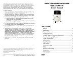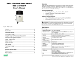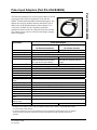
1
Pulse Input Adapters (Part # S-UCA/B-M006)
Part # S-UCA/B-M006
The Pulse Input Adapters are used to log the number of switch
closures per interval and are designed to work with the
HOBO® Weather Station and Micro Station data loggers. The
adapter has a plug-in modular connector that allows it to be
added easily to the Weather Station or Micro Station. Two
versions are available for easy interfacing with either
mechanical contact closures or solid-state electronic switches.
The contact closure version is ideal for connecting to tippingbucket rain gauges.
Specification
Pulse Input Adapter
S-UCA-M006
for Electronic Switches
Maximum Input Frequency
Measurement Range
Resolution
Lockout time
Recommended Input Type
Preferred Switch State†
Edge Detection
Minimum Pulse Width
Input/Output Impedance
Open Circuit Input Voltage
Maximum Input Voltage
User Connection
Operating Temperature
Range
Overall Cable Length
Housing
Housing Dimensions
Weight
Bits per Sample
Number of Data Channels *
Measurement Averaging
Option
Length of Smart Sensor
Network Cable
Part Number
S-UCB-M006
for Contact Closures
120 Hz (120 pulses per second)
2 Hz (2 pulses per second)
0 – 4093 pulses per logging interval
1 pulse
45 µs ± 10%
327 ms ± 10%
Electronic solid state switch closure or
Mechanical contact closure (example:
CMOS-level digital output (example:
reed switch in a tipping bucket rain
FET, opto-FET or open collector)
gauge)
Active low input
Normally open
Falling edge, Schmitt Trigger buffer (logic levels: low ≤ 0.6 V, high ≥ 2.7 V)
1 ms
100 KΩ
3.3 V
3.6 V
24 AWG wires, 2 leads: white(+), black(-)
-40° to 75°C (-40° to 167°F)
6.5 m (21 ft.)
Weatherproof PVC housing protects input adapter electronics
14 x 0.95 cm (5.5 x 0.375 in.)
310 g (11 oz.)
12
1
No (reports the number of pulses over the logging interval)
50 cm (1.6 ft.)
S-UCA-M006
S-UCB-M006
* A single HOBO Weather Station can accommodate 15 data channels and up to 100 m (328 ft.) of network cable
(the digital communications portion of the input adapter and smart sensor cables). A single HOBO Micro Station
can accommodate 4 data channels.
†
For maximum battery life, the Pulse Input Adapters should be used with their preferred switch type. The adapters
will work with active high inputs (S-UCA) and normally closed switches (S-UCB), but battery life will not be
optimized.
© 2003 Onset Computer Corporation
Part #: MAN-S-UCA/B
Doc #: 8129-A
Pulse Input Adapters
Inside this package
• Pulse Input Adapter
•
2 wire nuts
Connecting the Input Adapter
Typical Setup
The adapter housing should be installed outside the logger enclosure. Be sure to follow the instructions
included with the logger to ensure that the logger is properly sealed where the sensor cable exits the
logger enclosure. Secure the adapter housing to the mast or sensor mounting arm. Excess cable should be
coiled and secured with cable ties.
When making a connection to a third-party sensor, take time to make sure that the connection is reliable.
The connection should be protected from rain, dirt, and direct exposure to the elements. The input cable
can be connected directly to screw terminals on the sensor or to sensor cables with the included wire nuts.
To use the wire nuts, strip about 1 cm (3/8") of insulation from the end of wires, taking care not to nick
the metal conductors. Then, twist the stripped wires together clockwise and then screw on the wire nut
clockwise. Check the connection by gently pulling on the wires to verify a solid mechanical connection.
Always strain-relief the connection to make sure that the connection is not broken by being jerked or
repeatedly worked back and forth.
Installation Considerations
•
If sensor cables are left on the ground, use a conduit to protect against animals, lawn mowers,
exposure to chemicals, etc.
•
Refer to the HOBO Weather Station User’s Guide or the HOBO Micro Station User’s Guide for
information about setting up complete stations.
Input Connections
The Pulse Input Adapter sensor has two input connections. The white wire (+) is powered at 3.3 V
through a 100 KΩ resistor. This power is supplied from the logger’s battery. The black wire (-) is
connected through the adapter to the logger’s ground connection.
Typical Setup of S-UCB-M006 with a Tipping Bucket Rain Gauge or Mechanical Contact Switch
The Contact Closure Pulse Input Adapter (S-UCB-M006) is designed to work with Tipping Bucket Rain
Gauges and other devices with normally open, mechanical contact closure, switched outputs with a
maximum pulse frequency of 2 Hz. This sensor has a pre-set lockout time of 327 ms and is designed to
work with signals that must be de-bounced to be accurately measured.
Note
•
“Bounce” is a phenomenon where a single pulse may contain several false pulses or bounces.
De-bouncing a signal is typically required when measuring signals from mechanical switches,
contact closures, and reed switches.)
The lockout time prevents bounce-induced false pulses from being counted as separate switch closures. If
your gauge has a counter display and battery, disconnect them and connect the Pulse Input Adapter in
their place. In most cases, the black and white wires can be connected directly to the relay output. (When
Page 2 of 4
Pulse Input Adapters
connecting to relay or switch contacts, polarity does not matter.) A typical setup for connecting a sensor
with a mechanical switch output is shown below.
Pulse Input Adapter
3.3 Volts
100 K Ohms
Sensor
(Ex: Tipping Bucket
Rain Gauge)
Normally Open
Switch
1 K Ohms
White
Input Port
Black
GND
Figure 1: 2 Hz Pulse Input Adapter (S-UCB-M006) connected to a device that has a mechanical contact
closure output
Typical Setup of S-UCA-M006 with a FET Switch Transducer
The 120 Hz Pulse Input Adapter (S-UCA-M006) is designed for devices with a normally open solid-state
switch, FET switch or open collector, with a maximum pulse frequency of 120 Hz. This input adapter will
not work with sensors that have mechanical switch outputs, AC outputs, or outputs that must be debounced (see above). A typical setup of a FET switch transducer is shown below.
Pulse Input Adapter
3.3 Volts
100 K Ohms
Transducer
Pulse
Output
FET
White
1 K Ohms
Input Port
Black
GND
Figure 2: 120 Hz Pulse Input Adapter (S-UCA-M006) connected to a device that has a FET switch output
Note
•
The Pulse Input Adapters consume about 1 µA of current with the input high (switch open) and
about 33 µA with the input low (switch closed). For maximum logger battery life, use the Pulse
Input Adapters with normally open switches or with transducers that have a duty cycle of 90% or
higher.
Page 3 of 4
Pulse Input Adapters
Connecting to the Logger
To start using the Pulse Input Adapter, stop the logger and insert the adapter’s modular jack into an
available sensor connection port on the logger. If no port is available, use a 1-to-2 sensor connection
adapter (Onset Part # S-ADAPT), which allows you to plug two sensors into one port on the HOBO
Weather Station only. (The HOBO Weather Station supports a maximum of 15 data channels and 15
sensor ports. The HOBO Micro Station supports a maximum of 15 data channels and 4 sensor ports and
cannot be expanded with the 1-to-2 adapters.)
The logger automatically detects the new input adapter the next time you launch it. Launch the logger and
verify that the Pulse Input Adapter is functioning correctly. See the HOBO Weather Station User’s Guide
for more details about connecting HOBO smart sensors to the HOBO Weather Station.
Verifying Functionality
To verify proper operation of the Pulse Input Adapter, connect the adapter to a logger and launch the
logger. With the logger launched, enter a known number of pulses (for example, if using a tipping-bucket
rain gauge, tip the bucket several times). Then read out the logger and verify that the number of pulses in
the data file is correct.
If you think that the Pulse Input Adapter is not capturing pulses, check the connections to the adapter and
verify that the device being measured is functioning normally. If you believe the adapter is not working
properly, you can send the adapter back to Onset for repair. Contact Onset or your Onset Authorized
Dealer for a Return Merchandise Authorization (RMA) number.
Warranty
This product is warranted to be free from defects in material and workmanship for a period of one year
from the date of original purchase. During the warranty period, Onset will, at its option, either repair or
replace products that prove to be defective. This warranty is void if the Onset products have been
damaged by customer error or negligence, or if there has been an unauthorized modification.
Tune-up Service
Onset will examine and retest this or any other smart sensor or input adapter. A tune up fee may be
charged.
© 2003 Onset Computer Corporation. All rights reserved.
Onset and HOBO are registered trademarks of Onset Computer Corporation.
Part #: MAN-S-UCA/B
Document #: 8129-A
Page 4 of 4