1
AlarmView
Wireless Intruder Alarm System with
Visual Verification
User Guide
System version 2.08.38
AlarmView User Guide
DECLARATION OF CONFORMITY
Hereby,
Company: PIMA Electronic Systems Ltd
Address: 5 Hatzoref St., Holon 58856
Country: Israel
Telephone number: +972.3.6506414
Fax number: +972.3.5500442
PIMA Electronic Systems Ltd. declares that the AlarmView™ system is in compliance with the essential
requirements and other relevant provisions of Directive 1999/5/EC.
Federal Communications Commission (FCC) Part 15 Statement
This equipment has been tested to FCC requirements and has been found acceptable for use. The FCC requires the
following statement for your information.
This equipment generates and uses radio frequency energy and if not installed and used properly, that is, in strict accordance
with the manufacturer’s instructions, may cause interference to radio and television reception. It has been type tested and
found to comply with the limits for a Class B computing device in accordance with the specifications in Part 15 of FCC
Rules, which are designed to provide reasonable protection against such interference in a residential installation. However,
there is no guarantee that interference will not occur in a particular installation. If this equipment does cause interference to
radio or television reception, which can be determined by turning the equipment off and on, the user is encouraged to try to
correct the interference by one of the following measures:
If using an indoor antenna, have a quality outdoor antenna installed.
Reorient the receiving antenna until interference is reduced or eliminated.
Move the receiver away from the control/communicator.
Plug the control/communicator into a different outlet so that it and the receiver are on different branch circuits.
If necessary, the user should consult the dealer or an experienced radio/television technician for additional suggestions.
The user or installer may find the following booklet prepared by the Federal Communications Commission helpful:
“Interference Handbook.” This booklet is available from the U.S. Government Printing Office, Washington, DC 20402.
The user shall not make any changes or modifications to the equipment unless authorized by the Installation Instructions or
User’s Guide. Unauthorized changes or modifications could void the user’s authority to operate the equipment.
RoHS compliance - All our products are lead-free
PIMA Electronic Systems is ISO 9001 certified
All data contained herein is subject to change without prior notice.
PIMA Electronic Systems Ltd.
* Patent Pending Technology
Copyright 2013 © PIMA Electronic Systems Ltd. All rights reserved. E&OE
This guide and the information contained herein are proprietary to PIMA Electronic Systems Ltd. Only PIMA Electronic
Systems Ltd. or its customers have the right to use the information.
No part of this guide may be re-produced or transmitted in any form or by any means, electronic or mechanical, for any
purpose, without the express written permission of PIMA Electronic Systems Ltd.
PIMA Electronic Systems Ltd. owns patents and patent applications, trademarks, copyrights, or other intellectual property
rights covering the subject matter in this guide.
The furnishing of this guide to any party does not give that party or any third party any license to these patents, trademarks,
copyrights or other intellectual property rights, except as expressly provided in any written agreement of PIMA Electronic
Systems
Ltd.
Table of contents
1
2
3
4
5
6
7
Introduction ........................................................................................... 5
1.1 Graphic conventions in this guide ................................................................... 5
1.2 Features ..................................................................................................... 5
1.3 Visual-Verification ........................................................................................ 6
1.4 Specifications .............................................................................................. 6
1.4.1
Wireless network .................................................................................. 7
1.4.2
Communication .................................................................................... 7
1.4.3
Physical and electric attributes ............................................................... 7
Quick Reference Guide ........................................................................... 9
2.1 System components ..................................................................................... 9
2.2 Control Panel overview ................................................................................. 9
2.2.1
Key definition .................................................................................... 10
2.2.2
LCD display ....................................................................................... 10
2.2.3
Status messages ................................................................................ 11
2.2.4
Trouble icons ..................................................................................... 11
2.2.5
Audio indicators ................................................................................. 11
2.2.6
LED indicators.................................................................................... 11
2.3 INFO screen - system status ........................................................................ 12
2.4 Accessing the menus .................................................................................. 12
2.5 Default passwords ...................................................................................... 12
3.1
3.2
3.3
Global settings........................................................................................... 13
Zone bypass.............................................................................................. 13
User contacts ............................................................................................ 13
Event Log menu ................................................................................... 14
4.1 The log display .......................................................................................... 14
4.1.1
Log entry examples ............................................................................ 14
Service menu ....................................................................................... 15
5.1 Tests........................................................................................................
5.1.1
Zone test ..........................................................................................
5.1.2
External Siren ....................................................................................
5.1.3
Built-in siren......................................................................................
5.1.4
Communication ..................................................................................
5.1.5
System self-test .................................................................................
5.2 Enable programming ..................................................................................
5.3 System version ..........................................................................................
5.4 System reset .............................................................................................
6.1
6.2
6.3
7.1
7.2
8
9
Options menu....................................................................................... 13
15
15
16
16
16
17
17
18
18
Passwords menu .................................................................................. 19
Regular user passwords .............................................................................. 19
Master user password ................................................................................. 20
Duress code .............................................................................................. 20
Set Clock menu .................................................................................... 21
Time ........................................................................................................ 21
Date ........................................................................................................ 21
Stop Communication menu .................................................................. 22
9.1
9.2
Operating Instructions ......................................................................... 23
Arming modes ........................................................................................... 23
Arming the system ..................................................................................... 23
1
AlarmView User Guide
9.2.1
Using a key fob ..................................................................................
9.2.2
Via an external wireless keypad ............................................................
9.2.3
Force arm and faults overriding ............................................................
9.3 Disarming the system .................................................................................
9.4 Operating the system by text messages ........................................................
9.4.1
SMS commands .................................................................................
9.4.2
Receiving an SMS message ..................................................................
23
23
24
24
24
24
25
Appendixes
Appendix A
The AlarmView Smartphone Application ............................... 26
Appendix B
Maintenance & Troubleshooting ............................................ 30
Appendix C
Wireless Peripherals ............................................................. 32
Appendix D
Glossary ................................................................................ 41
Appendix E
Limited Warranty .................................................................. 43
Appendix F
Useful tables ......................................................................... 44
A.1
A.2
A.3
A.4
B.1
B.2
B.3
C.1
C.2
C.3
C.4
C.5
C.6
C.7
C.8
C.9
C.10
C.11
C.12
C.13
C.14
2
Installing the application .............................................................................
The interface .............................................................................................
Settings ....................................................................................................
Operating the application ............................................................................
26
27
28
28
Cleaning the LCD screen ............................................................................. 30
Replacing the Control Panel’s battery ............................................................ 30
Replacing the SmartView battery .................................................................. 31
SmartView PIR/Camera...............................................................................
OutView camera ........................................................................................
PIR-S Wireless PIR detector & PIR-P Wireless Pet-Immune PIR detector .............
TD-5 temperature detector ..........................................................................
DCM magnetic door contact .........................................................................
SM smoke detector.....................................................................................
DCO Carbon Monoxide detector ....................................................................
KF-1/KF-2 Remote control key fobs...............................................................
RWK Wireless keypad .................................................................................
REP Range extender (Repeater) ...................................................................
PCP Panic Pendant/Wrist watch ....................................................................
SIR B/R Wireless external siren ....................................................................
SIR-I Wireless Indoor siren..........................................................................
WLD Wireless Water leakage detector ...........................................................
32
32
32
33
33
34
34
35
36
37
38
38
39
40
Figure index
Figure 1.
Alarm visual verification .................................................................................... 6
Figure 2.
The Control Panel ............................................................................................. 9
Figure 3.
The Control Panel keys ...................................................................................... 9
Figure 4.
Control Panel’s back side .................................................................................. 10
Figure 5.
The LCD display .............................................................................................. 10
Figure 6.
Info screen example ........................................................................................ 12
Figure 7.
The smartphone app’s screen ............................................................................ 27
Figure 8.
Remove Bracket .............................................................................................. 31
Figure 9.
Replacing the SmartView battery ....................................................................... 31
Figure 10. SmartView PIR/Camera .................................................................................... 32
Figure 11. The OutView parts ........................................................................................... 32
Figure 12. Wireless PIR/ Pet-Immune detector ................................................................... 33
Figure 13. Temperature detector ...................................................................................... 33
Figure 14. Magnetic door contact ...................................................................................... 33
Figure 15. Smoke detector ............................................................................................... 34
Figure 16. Carbon Monoxide detector ................................................................................ 34
Figure 17. Remote control key fobs ................................................................................... 35
Figure 18. Wireless remote keypad ................................................................................... 36
Figure 19. REP Range extender (Repeater) ........................................................................ 37
Figure 20. Panic pendant/wrist watch ................................................................................ 38
Figure 21. Panic pendant ................................................................................................. 38
Figure 22. External siren ................................................................................................. 38
Figure 23. SIR-I Wireless Indoor siren ............................................................................... 39
Figure 24. Water leakage detector .................................................................................... 40
Default Master User Password: 1111
3
AlarmView User Guide
NOTICE AND DISCLAIMER
This guide is intended to assist users and operators in the safe and efficient use of the
system described herein. Before attempting to use the system, the user must read this
guide and become familiar with all safety requirements and operating procedures.
The system must not be used for purposes other than those for which it was designed.
The use of the software associated with the system is subject to the terms of the
license provided as part of the purchase documents.
PIMA Electronic Systems Ltd.’s exclusive warranty and liability is limited to the
warranty and liability statement provided in Appendix E on page 43.
This guide describes the maximum configuration of the system with the maximum
number of functions, including future options. Therefore, not all functions described
in this guide may be available in a specific system.
Warnings are given for situations and circumstances in which a possible hazard
can arise.
Cautions are given for situations or circumstances in which the system can possibly
be damaged.
Notes are given for situations that require special attention, or to improve the
operating procedure.
Incorrect operation, or failure of the operator to effectively maintain the system,
relieves the manufacturer (and seller) from all or any responsibility for consequent
noncompliance, damage, or injury.
The text and graphics contained in the guide are for the purpose of illustration and
reference only. In no event shall manufacturer be liable for any special, direct,
indirect, incidental, consequential, exemplary or punitive damages (including,
without limitation, any and all damages from business interruption, loss of profits or
revenue, cost of capital or loss of use of any property or capital or injury).
4
1: Introduction
1
Introduction
This guide is designed to assist you throughout the use of the AlarmView – a PIMA Wireless
Intruder Alarm System with visual verification.
PIMA Wireless products are easy to install, plug-n-play, providing wireless intruder alarm
capabilities with or without visual-verification & optional remote Look-in with a built-in GPRS/GSM
communication modem.
Suitable for residential and small business applications, the AlarmView system presents a
comprehensive solution for security and personal safety: see System components on page 9, for a
detailed list of the available components and accessories.
The AlarmView’s unique offering is in its ability to incorporate SmartView PIRs/ Cameras that
combine movement detection and image capturing, as well as OutView cameras and a wide range
of regular detectors, providing a comprehensive solution for Security and Personal safety.
Upon an alarm event, both the event and images are transmitted wirelessly to the AlarmView
Control Panel; the event code + 3 images are sent over the GPRS/GSM network directly to the
Central Monitoring Station and optionally to the mobile phone of a number of predefined users.
The AlarmView system offers:
Wireless alarm system with Visual-Verification & optional Look-in
Alarm & Visual reporting to Central Monitoring Stations
SmartView PIR-cameras
OutView cameras
A range of wireless peripherals such as movement/smoke detectors, panic buttons, remote
keypads, key fobs, door contacts, etc.
Optional Visual & Alarm End-user notification – to mobile phones or email
Optional use of mobile phone for Remote image request from each camera plus the ability
to Control the system remotely
1.1
Icon
Description
Note
Important note
Caution
Issues that may cause system malfunctions
Warning
Issues that may cause damage to the system or actual bodily harm
1.2
Graphic conventions in this guide
Features
“Matched field-of view” between detector and camera, for Visual Verification, with no
dead spots
High quality color images
Alarm event reporting:
ContactID, SIA Protocols over SMS/GPRS-IP
Images - Visual transmission over MMS/Email/GPRS
MMS (Multimedia Messaging Service) service requires Internet plan and costs money,
including text messages sent via this service.
5
AlarmView User Guide
End user notification by SMS & Email
Remote control of system activation and camera’s image requests, using SMS commands
from authenticated mobile phones
Built-in quad band GSM/GPRS communication modem
Advanced SmartView supervised wireless Visual link:
2 way supervised and secured radio network
48bit encryption key, Supervision every 10 sec
2.4Ghz FHSS (Frequency Hopping Spread Spectrum)
2.4Ghz Diversity receiver (2 antennas)
Supervised 868 MHz link for standard wireless peripherals
Graphic, user-friendly LCD display
Easy battery replacement
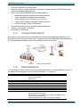
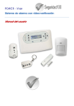
1.3
Visual-Verification
Upon alarm event, both the event information and images are transmitted wirelessly to the
AlarmView Control Panel; the event code + image are sent over GPRS/GSM network directly to
the Central Monitoring Station and/or the mobile phone of the end-user.
Figure 1.
1.4
Alarm visual verification
Specifications
The specifications listed below are for the system’s Control Panel, the specifications for each of
the detectors and accessories can be found in Appendix C, on page 32.
Number of wireless zones
Wireless Peripherals
Arming modes
Alarm types
Event log
Built-in siren
External siren
Input/Output
Real-time clock
Special functions
6
Up to 30: 24 regular (including 1 wired), 6 visual
Up to 6 Key fobs or keypads
Up to 6 Panic buttons
External siren
Away/Home/Partial
Silent, Siren or sounder (built-in)
256 events, with time & date stamp
Piezoelectric, 90dB
1 siren, wireless (Indoor/Outdoor)
1 PGM output, 3 trigger inputs
Time and Date stamp
Remote control by SMS from authorized mobile phones,
ensuring privacy and security.
Remote look-in via an MMS from an authorized mobile phone,
ensuring privacy and security.
Local USB connection for setup and firmware upgrade
1: Introduction
Codes
8 codes, up to 8 digits each (numeric value 1-4):
Master user
4 Regular users (or up to 4 digit code, numeric value 0-9,
with external keypad)
Duress code
Limited 24H code
Installer code
1.4.1
Wireless network
Advanced wireless link for Visual zones
Frequency Band
2.4 GHz ISM band
TX Power
Up to 100mW
Transmission method
2-way communication
GFSK
Frequency Hopping Spread Spectrum (FHSS)
Supervision
Up to 20 seconds
Secured Wireless Network
48-bit factory set ID code
Built-in security using a link key (prevents unauthorized
access)
Data encryption (up to 48-bit)
1
Expected Range
Up to 100 meters / 300 feet (indoor)
Wireless link for standard peripherals
Frequency
868 MHz
Supervision
Randomly, every 20 to 50 minutes
Transmission method
FM Narrow Band
Expected Range1
Up to 100 meters / 300 feet (indoor)
1.4.2
Modem
Interface
Report destinations
Reporting formats
End User contacts
CMS contacts
1.4.3
Physical Attributes
Dimensions
Weight:
With Battery
Without battery
Casing
Environmental Data
Operating
temperature
1
Communication
Quad-band GSM/GPRS
CMS Receivers, Mobile phones, Email Accounts
SMS/MMS/Email/GPRS-IP
Reporting Options/Formats:
GSM/GPRS, SMS/MMS/Email Notifications
Four cellular phone numbers
Four email accounts
Reporting Options/Formats:
GSM/GPRS, SMS/MMS/Email Notifications
Two IP address (programmable IP address and Port), Or
Two phone numbers, Or
Two Email accounts
Physical and electric attributes
225 x 138 x 40 mm
8.8 x 5.5 x 1.6 Inch
687 grams (1.5 pounds)
577 grams(1.3 pounds)
Plastic - PC/ABC 94/V0
-10ºC - +58ºC
+14ºF - +136.4ºF
Range is impacted by building materials and interference
7
AlarmView User Guide
Physical Attributes
Storage temperature
Humidity
Electrical Data
Power supply
Current drain
Backup battery
-25ºC - +70ºC
-13ºF - 158ºF
0 to 85%, non condensing
+12VDC/1A
100mA standby, 0.7A peak
+4.8 VDC,
4 x Ni-MH 2 Ah, up to 12 hours
To prevent damage to the Control Panel, use only the original AC adaptor and
backup battery pack.
8
2: Quick Reference Guide
2
Quick Reference Guide
2.1
System components
The AlarmView system consists of the Control Panel, 23 wireless zones, 1 hardwired, 6 PIR
camera (SmartView /OutView) and 36 wireless peripherals - up to 6 Key fobs/ Remote keypads,
and 6 Panic buttons, as well as one wireless siren.
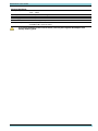
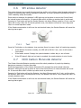
The Control Panel
The Control Panel is consists of the main circuitry, GPRS/GSM
communication module, standard wireless transceiver and a
visual dedicated wireless transceiver.
Visual detectors
Figure 2.
The SmartView supervised wireless PIR motion detectors are
composed of two types, which are combined with high-quality color cameras:
The Control Panel
SmartView: high quality rapid acquisition camera with PIR detector.
OutView: highly resistant outdoor camera with trigger input from external source detector, door bell, etc.
Wireless detectors
The AlarmView system supports a wide range of wireless detectors, including door contacts, PIR and
Pet-immune motion detectors, Smoke detectors, etc.
Sirens
The Control Panel has a built-in siren; an external wireless siren and strobe, or third party wired
siren can also be installed.
Key fobs/Remote controls
Key fobs & remote controls can be used to easily activate/deactivate the system.
Panic/Medical Pendant/Wrist watch
The AlarmView system can be used to transmit visual enhanced medical emergency and duress
alerts, using a wrist transmitter and/or emergency pendant.
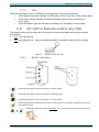
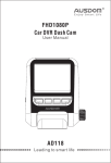
2.2
Control Panel overview
The next drawings show the Control Panel’s front and back.
Figure 3.
The Control Panel keys
9
AlarmView User Guide
Figure 4.
2.2.1
Control Panel’s back side2
Key definition
The table below details the Control Panel’s key definition and functions.
Arming keys
Description
Away
Arm to Away (full) mode
Home
Arm to Home (partial) mode
Part
Arm to Part (partial)mode
Function keys
Left
Access the menus/Select/Insert
Right
Display the system’s Status/Cancel/Delete
OK
Confirm
Navigation keys
Description
Up
Scroll up/alphanumeric values: A-Z, 0-9, #+,@-./space_!/numeral 1
Down
Scroll down/alphanumeric values (see above) /numeral 3
Left
Scroll left/Exit/back/numeral 4
Right
Scroll right/access/duplicate previous character/numeral 2
2.2.2
LCD display
The LCD screen shows at any given time the system status as well as the current time, GSM
service provider and signal level.
Figure 5.
2
The LCD display
The tamper switch is an order option and is only available if specified in the original order
10
2: Quick Reference Guide
2.2.3
Status messages
The available system status messages are:
Initializing (shown after startup, exiting programming mode and after a system reset
Disarm
Arm Away
Exit Delay
Entry Delay
Arm Home
Arm Part
2.2.4
Trouble icons
The available system trouble icons are:
Message transmission
Low backup battery
GSM reception level
Battery disconnected
GSM network error
GPRS transmission
AC loss
2.2.5
Audio indicators
Following are the sounds emitted by the Control Panel and the keypad:
♪
♪-♪
♪-♪-♪
♪-♪-♪-♪…
♪--------♪
Sound
Single beep
Two beeps
Three beeps
Continuous beeps
Long beep
Chime
2.2.6
Sounded when
A key is pressed
A menu idle timeout occurs – exiting to main menu
Successful command/operation
Entry/exit delay mode
Illegal command or entry refusal
The chime is activated
LED indicators
The table below shows the LED color indicators and their meaning.
LED
Color
Behavior
Green
Power on
Blank
Power loss
Blue, blinking
Wireless communication is active
Green, blinking
Cellular connection - OK
Off
No cellular connection
Orange, 3 blinks
Message waiting to be processed
Red
System trouble; see the display for information
11
AlarmView User Guide
LED
Color
Behavior
White, blinking
Alarm triggered – all modes; blinking will stop
when re-arming, or entering the system log.
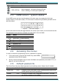
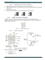
2.3
INFO screen - system status
In the INFO screen you can view the status of all active zones, by pressing the Info right
function button (in the main screen). The info screen consists of a grid showing all active zones
and their status.
Figure 6.
Info screen example
A zone with several events will toggle between the various open events, at one second intervals.
The applicable events and their indication are described in the next table:
Display
Event
Empty field Disabled or undefined zone
1-30
Active zone - normal condition
Open zone (“System not ready” state)
Open zone tamper
T
B
Bypassed zone
Low battery
Supervision loss
Alarm
X
2.4
Accessing the menus
In order to access the programming menus, a password is required.
1.
In the main screen, press the left function key under MENU;
a password entry field will appear.
2.
Use the numeric/navigation keys to enter the Master user password; see section 2
.2.1, on
page 10, on how to enter text.
2.5
Default passwords
The Control Panel has two default passwords and matching menus: Master User & Installer:
Password
Default
Master user
1111
Changing of User and Master codes, selecting system options and
partial system setup and programming
Installer
1234
Changing of Installer code, programming and setup. This code
can only be changed by the Installer.
12
Enables
3: Options menu
3
Options menu
This menu allows changing and controlling the general behavior of the Control Panel.
3.1
Global settings
Options
Global Settings
T Global Chime
T Remote Look-In
T Visual Events
The Global Settings menu allows to enable/disable the Global Chime, Remote Look-in, and Visual
events, to maximize your control of all privacy issues.
To change the global settings:
1.
Access the User menu and select Options Global Settings.
2.
Set/clear the options, which are:
a. Global Chime: enable/disable the Control Panel’s chime for all chime zones.
b. Remote Look-in: enable/disable Look-in image request by predefined mobile phone.
c. Visual Events: enable/disable sending Visual Verification images to predefined
mobile phone.
See the "Glossary", on page 41 for detailed explanation on the options.
3.2
Zone bypass
Options
Zone Bypass
£ Zone 1-24
£ Zone 25-30 (Visual)
This menu allows setting zones to be bypassed, i.e., not to trigger the alarm when opened.
Bypassing is used when the system needs to be armed, while one or more zones cannot be
armed. The zones selected will be bypassed during the next arming session and will automatically
return to normal, upon disarm.
To set zones for bypass:
1.
Access the User menu and select Options Zone Bypass.
2.
Set/Clear all relevant zones; note that only the enabled zones are listed.
Bypassing zones reduces the safety of the protected premises: a bypassed
zone does not sound the alarm when violated, nor does it report the CMS;
therefore it must be used carefully.
3.3
User contacts
Options
User Contacts
T User 1-4
The User Contacts menu allows temporarily disabling a user contact from receiving notifications,
or performing other normally allowed activities. To disable a user:
1.
Access the User menu and select Options User Account.
2.
Clear to disable, or Set to enable relevant users.
13
AlarmView User Guide
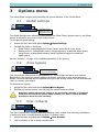
4
Event Log menu
21/07/13
Event Log
05:26:33
1
Communication Loss
GSM
CANCEL
The Event Log menu allows viewing the system log. The log keeps the last 256 events.
While the system is armed, only 10 events from the same zone can be logged.
To view the Event Log:
1.
Access the User menu and select Event Log. The display will show the last chronological
event in the log.
2.
Use the Up/Down
3.
Press "Cancel" to exit the log.
4.1
navigation keys to scroll the events; see next section for details.
The log display
Every log entry is displayed in three lines (see the examples):
a.
The upper line shows the date/time stamp and the entry number on the right.
b.
The mid line shows the event description
c.
The bottom line shows the zone/event source.
4.1.1
14
Log entry examples
5: Service menu
5
Service menu
5.1
Tests
Service
Tests
Zone
Test
External Siren
Stop Siren
Built-In Siren
Relearn
Communication
System Self Test
GPRS Link
CMS 1-2
Contact 1-4
Tests help ensuring proper operation of the system. You should test you're alarm system on a
regular basis, once every week.
5.1.1
Zone test
This test should be performed periodically, to ensure that all the detectors work properly.
To perform the zone test:
1.
Access the User menu and select Service Tests Zone.
2.
All the enabled zones will appear in a grid, with the zone number of regular zones, and the
RSSI (Received Signal strength Indication) level of visual zones; see the next sub-sections.
3.
Trigger each regular zone - once the zone signal is received, the zone number is replaced by
its RSSI level bars.
4.
Once the tests are complete, press OK to exit.
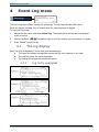
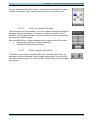
5.1.1.1
Zone status options
There are three status options for a zone display (see the next figure):
a. Number: this is the zone number. It appears in regular zones before testing, and in fault
visual zones with, for example, low battery or supervision loss.
b. RSSI bars:
1)
In regular zones: the bars appear as the zone is triggered;
2)
In visual zones: the bars appear normally and constantly interchange with the
zone number.
c. Empty: this indicates that the zone is not in use (disabled).
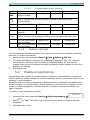
5.1.1.2
RSSI reception level
The Received Signal Strength Indicator or RSSI, helps determining if a wireless device is placed at a
location where it can maintain good communication with the Control Panel.
As in a cell phone, the more bars that appear the better is the reception, and vice versa:
15
AlarmView User Guide
1
2
11
12
13
5
6
7
14
15
16
17
24
25
10
19
20
5 bars: Excellent reception;
4 bars: Very good reception;
3 bars: Good reception;
2 bars: Low reception - relocating the detector is advisable;
One bar: Poor reception- relocating the detector is required!
5.1.2
External Siren
5.1.2.1
Test
To test the siren:
1.
Access the User menu and select Service Tests External Siren Test
2.
The external siren will sound two separate beeps, then a third longer one.
3.
Press OK.
5.1.2.2
Relearn
Installer only option.
5.1.3
Built-in siren
The test verifies the behavior of the built-in siren. To perform the test:
1.
Access the User menu and select Service Tests Built-In Siren.
2.
Press OK; the built-in siren should sound briefly.
5.1.4
Communication
The test verifies the communication setup, by attempting to send and receive data; see the next
table for details. To perform a communication test:
1.
Access the User menu and select Service Tests Communication.
2.
Select the communication test type; see the next table.
3.
Press OK at the end of the test.
16
5: Service menu
5.1.4.1
Communication test options
Type
GPRS
LINK
Test Process
An attempt to open
Google©'s website
Target
LCD Message
www.google.com
Wait
CMS
1...2
Sends a “Periodic Test” event to the CMS (reporting is dependent on the
protocol defined).
Response
Passed/Failed
ContactID/SIA SMS
CMS phone
Wait
Passed/Failed
Email visual/ContactID
CMS email
Wait
Passed/Failed
GPRS ContactID/Visual
ContactID
CMS IP & port
Wait
Passed/Failed
Contact
Sends a “Periodic Test” message via SMS & email, and reports after each test.
1...4
SMS Test (Event Report
must be enabled)
Email Test (Event Report
must be enabled)
5.1.5
Mobile phone
Test SMS
Passed/Failed
Email address
Test email
Passed/Failed
System self-test
The test initiates an automatic sequence of the system, which checks the processor, the screen
and more. To perform the self-test:
1.
Access the User menu and select Service Tests System Self Test.
2.
The system will activate a sequence of the display and audio tests, LED, LCD, siren and
internal speaker. After that, the CPU, Memory, GSM/GPRS modem, RF, and more are
checked. When the test is complete the system will display a status message of either Ok or
detailed error message.
3.
Press Back to exit.
5.2
Enable programming
Programming by the Installer of the alarm system is required on some occasions, like when the
need to update the system's software or see its configuration arises. It can be done locally, on the
premises, or by the telephone.
By default, local and remote programming is disabled and must be enabled by the Master user’s
special permission. For security reasons, only the Master user can allow this. It enables a 2 hour
window, in which programming is allowed. After the 2 hours are up it must be enabled once
again, if required
To enable a 2 hour programming window:
Enable programming
For 2 hours ?
1.
Access the User menu and select Service Enable programming
2.
Press
for "Yes". The built-in siren will sound 3 beeps and a confirmation message
will appear.
3.
Press Back twice to exit.
YES
NO
17
AlarmView User Guide
5.3
System version
To view the system version:
1.
Access the User menu and select Service Display Version.
2.
The Control Panel’s software version will be displayed.
3.
Press OK to exit.
5.4
System reset
This feature is to be used mainly to reset the GSM communication between the control panel and
the GSM network. It behaves the same as disconnecting the control power from power briefly and
does not affect settings like zone names, telephone numbers, etc.
To perform a system reset:
1.
Access the User menu and select Service System Reset.
2.
Wait shortly for the process to end and the main display to appear.
18
6: Passwords menu
6
Passwords menu
The password menu allows you to define and set passwords used for the various functions of the
system, using a level hierarchy password system.
Passwords
Regular Users
Master User
Duress Code
24H Limited Code
Installer
6.1
Regular user passwords
Here you can define up to 4 users of the AlarmView, with name and password for each. The
passwords only allow their users to arm and disarm the system.
The password functionality depends on whether it is entered at the Control Panel or in a
wireless keypad:
Passwords that are to be entered in the Control Panel can be made of up to 8 digits and
contain only the numeric values of 1-4, for example 13423142.
Password that are to be entered solely in the RWK wireless keypad can be made of up to 4
digits, but contain the numeric values of 0-9, for example 0369.
Due to EN50131-1 regulation and “Grade 2” approval, the system allows only
21 attempts to enter password/code (on the wireless keypad only). A Tamper
event is generated on the 22nd attempt.
EN50131-1 regulation and “Grade 2” approval require the use of a minimum of 7 digit
passwords; when using the Control Panel without s keypad you can use 1-4 numeric
values only.
Passwords
Regular Users
User 1-4
Name
Password
To set passwords for regular users:
1.
Access the User menu and select Passwords Regular Users User X.
2.
Select Name and enter a user name; see section 2
.2.1, on page 10 on how to.
3.
Press OK.
4.
Select Password and enter a password; see section 2
.2.1, on page 10 on how to.
5.
Press OK.
To entirely delete a password delete all the digits, leaving it blank, and press OK.
19
AlarmView User Guide
6.2
Master user password
The Master user password is used to access the user menu (and to arm/disarm). This password
can be up to 8 digits long and contain the numeric values of 1-4, for example 41241324.
The default Master user password must be changed, to complete the
installation and setup process.
The Master password cannot be entered on a wireless keypad, only directly in
the Control Panel.
“Grade 2” approval requires the use of a minimum of 7 digit passwords.
To set the Master password:
1.
Access the User menu and select Passwords Master User.
2.
Enter the desired password; see section 2
.2.1, on page 10, on how to.
3.
Press OK.
6.3
Duress code
The Duress code is used when a user is forced to disarm the alarm system by an intruder. When
this code in entered, the system is indeed disarmed, as in normal disarming, however, a “Duress”
event is sent to the Monitoring Station (where available) and the system’s contacts.
As a precaution, the LCD screen shows no indication for the duress reporting; only the envelope
icon appears to indicate normal “Disarm” reporting.
The Duress code can be up to 8 digits long and can contain the numeric values of 1 through 4, for
example 44312411.
To help you remember the Duress code in stressful situations, use your User code,
but switch around the last two digits; for example, if your user code is 33142324,
the Duress code should be 33142342.
To set the Duress code:
1.
Access the User menu and select Passwords Duress Code.
2.
Enter the desired password; see section 2
.2.1, on page 10 on how to.
3.
Press OK.
20
7: Set Clock menu
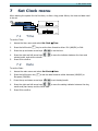
7
Set Clock menu
When starting the system for the first time, or after a long power failure, the time and date need
to be set.
Set Clock
16 : 34
Time
AM-PM/24H
CANCEL
Date
16 / 04 / 13
DD-MM/MM-DD
7.1
CANCEL
Time
To set the Time:
1.
Access the User menu and select Set Clock Time.
2.
Press the left function
3.
Press the up and down arrow keys
to set the hour.
4.
Press the right and left arrow keys
minute boxes, and set the minute.
to move the indicator between the hour and
5.
Press OK to confirm.
7.2
key to set the time format to either 12H (AM/PM) or 24H.
Date
To set the Date:
1.
Access the main menu and select Set Clock Date.
2.
Press the left function key
European (DD/MM).
3.
Press the up and down arrow keys
4.
Press the right and left arrow keys
to move the setting indicator between the day,
month and year boxes, and the other data.
5.
Press OK to confirm.
to set the date format to either American (MM/DD) or
to set the day/month.
21
AlarmView User Guide
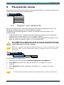
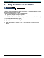
8
Stop Communication menu
Stop Comm.
Are you sure ?
YES
NO
This option allows you to temporarily stop all communication - all pending messages are cancelled
and all communication buffers are cleared.
The Stop Communication option is used in the following cases:
a.
During the installation process (by the Installer).
b.
During testing of the system (by the Installer).
c.
In the event of a false alarm, when entering or exiting the premises (by the Master user).
To stop communication and clear the buffers:
1.
Access the User menu and select Stop Comm.
2.
Press OK.
3.
Press Yes to confirm; all messages in queue, if there are any, will be erased and will not
be sent.
22
9: Operating Instructions
9
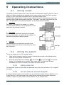
Operating Instructions
9.1
Arming modes
The following section explains how to arm and disarm the AlarmView system, using the various
options. All these options are also available when using a remote control, key fob or wireless
keypad, or when using SMS commands from an authorized cellular phone.
The AlarmView system allows 3 arming modes, defined during the programming process and
allowing a fully flexible and complete protection. The modes - Arm away, Arm Home and Arm
Part - are illustrated in the following diagrams; the protected areas are shaded.
Arm Away
Full arming of all zones in the system, i.e., all door
contacts, motion detectors, etc. are activated, is to be
used when the premises is vacant.
Arm Home
Home arming is a perimeter arming of all perimeter
sensors and detectors, as defined by the Installer. For
use when home/office is partly occupied.
Arm Part
Partial arming is to be used when one part of the
premises needs to be secured, while leaving the other
part unsecured.
9.2
Arming the system
To arm the system to any of the arming modes:
1.
Verify that the system is ready for arming: all zones that are part of the defined arming
mode are closed, except exit delay ones.
2.
Press the appropriate key: Arm Away
, Arm Home
, or Arm Part
; if "One-Key
Arming" is not enabled by the Installer, enter a user code. The Exit delay will start
immediately. As soon as it expires, the system will become armed.
9.2.1
Using a key fob
The AlarmView system can be armed and disarmed using a key fob; see section C.8, on page 35
for details.
9.2.2
Via an external wireless keypad
A wireless external keypad can be used to arm and disarm the system, either in addition to the
Control Panel or as a single keypad. User codes that are entered at the wireless keypad are
limited to 4 digits only, with numeric values between 0-9, for example 0486.
23
AlarmView User Guide
However, the Master user password cannot be used via the wireless keypad, but only at the
Control Panel.
9.2.3
Force arm and faults overriding
9.2.3.1
Force arm
"Force arm" is a feature that allows the exit delay to start running, even when non exit delayed
zones are open (“System not ready”). This feature can be enabled by the Installer. All open zones
must be closed before the exit delay expires, or an alarm will be set off.
9.2.3.2
Faults overriding
Three faults can be overridden and ignored, so the alarm system can be armed even if one of
them occurs. The faults are Backup battery loss, AC loss and Zone supervision loss. This
feature too can be enabled by the Installer.
The three faults will be logged and reported anyway.
9.3
Disarming the system
There are two ways to disarm the system:
By entering a User code;
By entering the Duress code; (see section 6
.3, on page 20).
See the “Glossary”, on page 41 for more details.
9.4
Operating the system by text messages
The AlarmView system can be operated by SMS messages. Operations include arming &
disarming, requesting the system status, activating the PGM output, stopping the siren and
requesting look-in images.
By using Caller ID authentication, only user contact cell phones are accepted by the Control Panel.
Furthermore, the security settings and actions allowed for each and every phone number (i.e.,
contact) can be managed separately.
To send a command, simply type the letter/s listed bellow and send it to the system’s phone
number as a text message. A status message confirming (or reporting failure) your command
should be received from the system.
Note that commands are NOT case sensitive.
9.4.1
SMS commands
Following are the available text commands* you can utilize by using the cellular phone.
Action
Arming commands
Arm Away
Arm Home
Text
Shortcut
AWAY
HOME
A, a
H, h
Arm Partial
Disarm
PGM commands
Open PGM
Close PGM
PARTIAL
DISARM
P, p
D, d
24
1O/o
1C/c
9: Operating Instructions
Visual Look-in commands
Request Image
xxI/i
xx – zone number
Available zones are 25-30
99 – all 25-30 zones
Miscellaneous commands
Stop Bell
BELL
B, b
Check System Status STATUS
S, s
Help - Request a list ?
of commands
* Commands are NOT case sensitive
9.4.2
Receiving an SMS message
The SMS messages sent by the Control Panel are built out of the following format:
Message + Device Name/User Name + time stamp; for example, "Alarm from Kitchen
AlarmView 02:38:26".
25
AlarmView User Guide
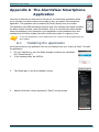
Appendix A The AlarmView Smartphone
Application
Currently for Android only and soon for iPhone too, the AlarmView application allows
you to operate your alarm system via a simple-to-use, icon based, free smartphone
application. The application can be obtained by Email, directly from your vendor.
The application uses SMS technology behind a clear user interface that makes operating
the alarm system remotely, quick and intuitive. Just as in controlling the alarm system
using text messages, every operation by the application is being answered by a text
message from the alarm system that either confirms the action or reports on error.
To use the application, some parameters are required to be programming by
the Installer.
A.1
Installing the application
As mentioned above, the application’s file can be obtained from your vendor by Email. To install
the application:
1.
On your Smartphone, open the Email message containing the installation
file (“AlarmView.apk”).
2.
In the message body, tap INSTALL.
3.
Tap Install again in the first installation screen.
4.
Read the End-User License Agreement (“EULA”) and tap Accept.
26
Appendix A: The AlarmView Smartphone Application
5.
When installation ends, click Open.
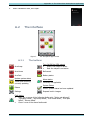
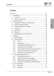
A.2
The interface
Figure 7.
A.2.1
The smartphone app’s screen
The buttons
Arm Away
Turn On/Off the PGM output
Green: the output is active
Red: the output is not active
Arm Home
Bell cancel
Arm Part
Battery status
Update system status
Yellow and swiveling:
currently updating
Disarm
Settings
Alarm status
Currently not applicable
System Status
Green: system status has been updated
Request look-in images
Fault status
Red: one or more of the following faults exist: "Action not allowed",
"Operation failed", "Arm away failed", "Arm home failed", "Arm part
failed", "Disarm failed"
Green: none of the above faults exist
27
AlarmView User Guide
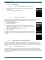
A.3
Settings
A.3.1
The Control Panel’s phone number
1.
To set the Control Panel’s mobile phone number, tap the Settings icon
(bottom left).
2.
Enter the number in the designated space.
A.3.2
Password protection
The application can be protected by a password, so to open it will require the user to enter a
password. The default password, after enabling this feature, is four zeros (‘0000’).
To set a different password:
1.
Tap to select “Enable Password”.
2.
Tap “Change Password”.
3.
Enter the current password. Failing to enter the correct password will
prevent entering a new one. If this is the first time you enter a password,
enter ‘0000’ as the current one.
4.
Enter a new password and enter again to confirm it.
5.
Tap “Set password”
From now on, every time you’ll try to open the application, a logon window will
be displayed. To remove it and cancel the password feature, de-select “Enable
Password”.
A.4
Operating the application
When opening the application and before updating the status or performing any action, the
buttons are all in gray. As the system status is updated or an action is taken, for instance when
tapping the Sync button, they become colorful and remain so for 20 seconds, before returning to
be gray.
A.4.1
Arming & disarming
To perform an action, just tap the appropriate icon. The AlarmView’s Control Panel will send a
confirmation (or error) message, as soon as the action (e.g., disarming the system) is taken; the
relevant icons in the application will be colored: arming icons lights in red when active, disarm(ed)
in green, and so on.
28
Appendix A: The AlarmView Smartphone Application
Also, the status icons will light in green, depending to their status: low battery
in green (otherwise in gray), faults in green when there ones, and so on.
A.4.2
Look-in image request
Tap the camera icon at the bottom - a pop-up window showing the cameras, is
displayed (see the next image). To receive an image from camera #1-6 (if
installed), tap the camera’s button. The Control Panel will respond by sending
an image as an MMS message.
When an MMS arrives, a popup message with the camera icon will be shown
Pressing OK will open the incoming message
Pressing Cancel will close the popup.
A.4.3
PGM output activation
The PGM icon (and output) has two states (as in the PGM output itself), as
explained in the previous table. Being a toggle mode output, every tap turns
the output’s state to either On or Off, and as a result the icon’s color becomes
red or green.
29
AlarmView User Guide
Appendix B Maintenance & Troubleshooting
B.1
Cleaning the LCD screen
The LCD screen may occasionally get finger oil stains and accumulate dust. Clean it only with a
soft dry cloth or a special screen cleanser. Avoid the use of abrasives of any kind.
Never use solvents such as Kerosene, Acetone or Thinner; these will harm
the external finish and damage the transparency of the window.
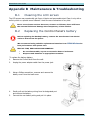
B.2
Replacing the Control Panel’s battery
Before replacing the backup battery, remove the transformer from the AC
outlet or disconnect the power.
We recommend using suitable replacement batteries from
best performance and system care.
PIMA Wireless for
RISK OF FIRE, EXPLOSION AND BURNING!
Do not disassemble, expose to excessive heat or incinerate.
Dispose used batteries in appropriate container.
To replace the backup battery:
1.
Remove the Control Panel from the wall.
2.
Unplug the power adapter cable from the power jack.
3.
Using a Philips screwdriver, unscrew and remove the
battery cover from the back cover.
4.
Gently pull out the battery wiring from its designated port
and remove the battery.
5.
Connect the new battery wiring and put it in place.
30
Appendix B: Maintenance & Troubleshooting
Use suitable replacement batteries from Pima Alarm Systems for best
performance and system care.
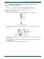
B.3
Replacing the SmartView battery
The battery used in the SmartView detector is Energizer Lithium L91 1.5v.
To Replace the SmartView battery:
1.
Release the screw fastening the bracket to the detector and remove the bracket.
Figure 8.
2.
Remove Bracket
Remove the screw fastening the battery compartment cover to the detector and remove
the cover.
Figure 9.
Replacing the SmartView battery
3.
Replace the two batteries with a fresh set (see sticker on the battery holder compartment for
correct polarity).
4.
The blue indication LED will light up for 2-4 seconds and then go off, indicating the batteries
are installed correctly.
5.
Close the battery compartment cover and fasten the screw.
31
AlarmView User Guide
Appendix C
Wireless Peripherals
This section gives a detailed explanation of each of the available SmartView family and additional
Wireless detectors and peripherals.
C.1
SmartView PIR/Camera
The SmartView is a supervised wireless digital PIR motion detector,
combined with a VGA high-quality color camera.
Used for a wide range of home and office applications, it is designed for
easy installation, with no required vertical adjustment.
Using an authenticated, two-way, encrypted wireless link, (2.4 GHz, FHSS),
it ensures excellent indoor coverage, allowing the transmission of highquality color-VGA images, utilizing low power technology.
Figure 10. SmartView
PIR/Camera
The SmartView has a unique technology called Rapid Image Acquisition, for supplying the Visual
images. It also includes a diagonal lens with 11 lenses that lets covering 22 zones, delivering
uniform detection sensitivity to a range of up to 7 meters.
The SmartView unique feature of ‘Matched field-of view’ between camera and detector, allows
simple installation at any place in the premises, knowing that the area covered by the camera is also
the protected area, and there is no need for adjustment or alignment of the detector or camera.
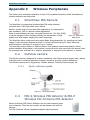
C.2
OutView camera
The OutView camera is designed for outdoor installations, and utilizes external trigger input, making
it ultimate tool for enhanced perimeter protection as well as a variety of other applications.
The OutView camera can be triggered by :Outdoor detector, Doorbell, Electronic-gate, etc.
C.2.1
Quick reference guide
Figure 11. The OutView parts
C.3
PIR-S Wireless PIR detector & PIR-P
Wireless Pet-Immune PIR detector
Passive Infra-Red (PIR) Motion Detectors are the most frequently used
type of detector. There are two models: normal detector and with Pet
immune.
The PIR-S detector utilizes a digitalized adaptive signal processor
32
Appendix C: Wireless Peripherals
algorithm. It is made up of a cover and a base: the cover contains the
electronics and optics; the base has knockouts to allow mounting
on flat surfaces or in a corner situation (using a triangular bracket).
Figure 12. Wireless PIR/
Pet-Immune detector
The detectors are designed to give a typical detection range of 12 meters, when mounted at 2
meters above ground.
The PIR-P Pet-Immune PIR detector eliminates false alarms caused by pets. It is designed not
initiate the alarm when detecting a dog weighing up to 27Kg, few cats, etc.
C.3.1
Test
The detector can be put into Test mode, by pressing its LED. In Test mode, the power consumption
timer will be turned off and the LED indicator will flash every time a movement is detected.
Each time the Test button is pressed, it enters the test mode for 3 minutes, during which the unit
will transmit a test signal to the Control panel for radio range test.
After 3 minutes it will exit Test Mode automatically and return to normal mode.
C.4
TD-5 temperature detector
The wireless temperature detector generates an alarm when the surrounding temperature drops
to 5ºC (41ºF).
Figure 13.
C.5
Temperature detector
DCM magnetic door contact
The wireless magnetic door contact is used for detecting the opening and closing of doors and
windows. Best used where there are small children or in shops and warehouses, the door contact
is typically fixed to the doorframe/windowsill and the magnet is fixed to the door or window.
While the AlarmView system is disarmed, every time a magnet door or window is opened, the
Control Panels chime sounds a long beep. While the system is armed, however, an alarm is
generated, just like any other detector.
To turn the chime off completely, see section 3.1, on page 13.
Figure 14.
Magnetic door contact
33
AlarmView User Guide
C.6
SM smoke detector
The smoke detector has a small foot print and low profile, yet it utilizes optical chamber technology,
freeing it from potentially harmful radioactive materials. It is micro-process controlled and offers
100% reliability, safety and quality.
Once smoke is detected, the detector’s LED lights up and an alarm is sent to the Control Panel.
An internal buzzer will sound for 10 seconds after which a follow-up smoke check is performed.
Pressing the Test button will put the Smoke Detector into Alarm Silence mode for 10 min. and the
alarm will be stop. After this 10-minute period is over, the detector will emit a 2-tone beep and
return to normal operation mode
If the Smoke concentration is still over the set threshold value, the Smoke Detector will sound the
warning alarm again.
Figure 15.
C.6.1
Smoke detector
Test
Press the Test button on the detector (see previous figure) to ensure that it is functioning properly:
If the detector functions normally, the LED will be ON for 2 sec., then it will sound a
2 tone beep.
If the buzzer sounds 3 beeps, the optical chamber is either dirty or out-of-order.
If the LED doesn’t light and no beep is sounded, the smoke detector is out-of-order.
C.7
DCO Carbon Monoxide detector
The Carbon Monoxide Detector provides round-the-clock protection of people by detecting
dangerous presence of carbon monoxide.
Once the concentration of the Carbon Monoxide (CO) exceeds the set threshold value the
detector’s LED lights up and an alarm is sent to the Control Panel. An internal buzzer will sound
for 10 seconds after which a follow-up smoke check is performed.
Pressing the Test button will put the Detector into Alarm Silence mode for 10 min. and the alarm
will be stop. After this 10-minute period is over, the detector will emit a 2-tone beep and return to
normal operation mode
If the Smoke concentration is still over the set threshold value, the Smoke Detector will sound the
warning alarm again.
Figure 16.
34
Carbon Monoxide detector
Appendix C: Wireless Peripherals
C.7.1
Test
Press the Test button on the CO Detector to ensure that it is functioning properly:
If the detector functions normally, the LED will be on for 2 sec. then it will sound a beep.
If the buzzer sounds 3 beeps, the Electro-chemical sensor on the CO detector is
out-of-order.
If the LED doesn’t light and no beep is sounded, the CO detector is out-of-order.
C.8
KF-1/KF-2 Remote control key fobs
The remote control key fob offers the convenience of arming and disarming the alarm system
at a distance.
KF-1: one-way key fob
KF-2: two-way key fob – every successful operation is indicated in the key fob by a beep
Figure 17.
C.8.1
Remote control key fobs
Quick reference
Pressing this button arms the system in Away mode
Pressing this button arms the system in Partial mode
Pressing this button arms the system in Home mode
Pressing this button disarms the system. If the alarm is sounding, pressing this button
will stop the siren.
Pressing these two buttons together for 1 second will produce a Panic alarm
35
AlarmView User Guide
C.8.2
Replacing the key fob's battery
1.
Remove the battery cover by using a coin to turn it counter-clockwise
2.
Insert the battery as shown in the diagram, with the unmarked side (negative) of the battery
facing down
3.
Replace the battery cover
4.
Secure the cover by using a coin to turn clockwise; see the next figures
C.9
RWK Wireless keypad
The RWK is a two way wireless keypad that can be used to enhance accessibility in large
locations, where there is a need for more than one entry/exit point, or when the Alarm system is
installed away from the door.
Figure 18.
Wireless remote keypad
C.9.1
Quick reference
C.9.2
Alarm key combinations
Press the following key combinations together, to trigger:
36
a.
Panic alarm: 1 + 3
b.
Fire alarm: 4 + 6
c.
Medical alarm: 7 + 9
Appendix C: Wireless Peripherals
C.9.3
LED indicators
The remote wireless keypad LED indicators behave as follows:
Power LED (Red):
Steady: system OK
Flashing: low battery
Status LED (tricolor)
Steady Red: armed Away
Flashing Red: armed Home
Steady Orange : armed Part
Steady Green: disarmed
Flashing Green: fault
Fault LED
Currently inactive
C.9.4
Operating instructions
Arming the system using the remote keypad is done using one key arming. Press the desired Arm
Away, Arm Home, or Arm Part key to arm the system.
To disarm the system enter a valid user code and press the keypads Disarm button.
C.9.5
Replacing the battery
1.
Remove the keypad from the wall.
2.
Open the Keypad by loosening the 2 screws located on the back of the unit.
3.
Remove the battery and press any key to discharge.
4.
Insert a new battery into place.
5.
Replace the keypad’s cover and secure with the two screws.
6.
Remount the unit onto the wall.
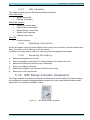
C.10
REP Range extender (Repeater)
The Range extender is designed to increase the effectiveness and versatility of the alarm system,
by increasing the maximum possible distance between the control panel and the detectors and
peripherals. It is available in 868MHZ version.
Figure 19.
REP Range extender (Repeater)
37
AlarmView User Guide
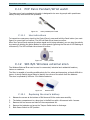
C.11
PCP Panic Pendant/Wrist watch
The water proof panic pendant/wrist watch is designed to be worn by people with special care
needs, as they move around the premises.
Figure 20.
C.11.1
Panic pendant/wrist watch
Use instructions
To transmit an emergency signal to the Control Panel, press and hold the Panic button (see next
figure) for more than one second. The LED will flash three times to confirm.
When the Control Panel receives the alarm signal and is being activated, you can stop the activity
by pressing & holding the Active Button for eight seconds (ignoring the first set of LED flashing at
one second). The LED will flash three times to confirm.
Figure 21.
C.12
Panic pendant
SIR B/R Wireless external siren
The Wireless External Siren can be used in commercial, industrial and residential locations,
indoors or outdoors.
The Siren is capable of providing audible alerts for fire, alarm and tampering, at levels difficult to
ignore. A strong flashing signal helps to identify the source of the alarm from the distance.
The siren is operated by 4xD size 1.5v Alkaline batteries.
Figure 22.
C.12.1
External siren
Replacing the siren's battery
1.
Release the screws at the bottom of Bell box and lift the outer case carefully.
2.
The battery compartment is a large box in the Bell box with a lid secured with 4 screws.
3.
Remove the four screws and take off the compartment lid.
4.
Remove the batteries and press the Tamper Switch twice to discharge.
5.
Slide Power Switch to OFF position.
38
Appendix C: Wireless Peripherals
6.
Insert new batteries and slide Power Switch back to ON position.
7.
The Bell box will beep and flash when the last battery is inserted.
8.
Replace the battery compartment lid with the four screws and not to over tighten.
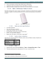
C.13
SIR-I Wireless Indoor siren
The Indoor Wireless Siren can be used is commercial, industrial and residential indoor locations.
The Siren is capable of providing audible alerts for fire, alarm and tampering at levels difficult
to ignore.
Figure 23.
C.13.1
SIR-I Wireless Indoor siren
Features and specifications
Low battery detection
Case and wall tamper protection
System status indicator with siren beeps
Programmable cut-off options via the Control Panel
Power: 4 x D size Alkaline batteries3
Range: Over 300 meters (~1000 feet) in open space4
C.13.2
Audio status indication
The indoor siren uses the following indications while in Arm and Disarm modes; all options are
defined via the Control Panel:
Mode
Siren audio
Arm/Home
1 beep
Arm Key fob
5 beeps
Disarm (Low Battery)
2 beeps
C.13.3
Test
1.
Access the User menu and select Service -> Tests -> External Siren test -> Test.
2.
The siren should sound for a few seconds. If it is not, re-enroll the siren.
3
Three years life expectancy in typical domestic environment
4
Range might be impacted by building materials and interferences
39
AlarmView User Guide
C.13.4
Replacing the batteries
1.
Release the side screw of the box and lift the outer case carefully.
2.
Remove the battery compartment lid’s 4 screws and take it off.
3.
Remove all 4 batteries.
4.
Press the Tamper switch twice to discharge.
5.
Insert the new batteries.
6.
The siren will give a short confirmation tone.
7.
Replace the battery compartment lid with the four screws and close the case.
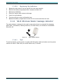
C.14
WLD Wireless Water leakage detector
The water detector is designed to be used in areas where there is a potential for damaging
water leaks - dishwashers, washing machines, hot water tanks, air conditioner condensation
drip pans, etc.
Figure 24.
C.14.1
Water leakage detector
Test
To test the detector, put the probe in a glass with little water inside and make sure the system
receives the alarm. Check that you receive alarm every 3 minutes.
40
Appendix D: Glossary
Appendix D
Glossary
Alarm types:
Burglary Alarm – An alarm caused by a violation of one or more of the zones.
Fire Alarm – An alarm initiated due to a violation of one or more of the fire zones
(heat, smoke detectors).
Tamper Alarm – An alarm caused by an open tamper protection, for example when
someone attempts to remove a detector or (optionally) the Control Panel from the wall.
Panic/Medical/Emergency Alarm – An alarm due to an activation of a panic/
distress button or medical detector.
Arming modes:
Away – Full arming of the system, best used when there is no one at home/office.
Home – Home arming is a perimeter arming of perimeter detectors as defined by the
installer. For use when home/office is partly occupied.
Part – Partial arming is designed for securing one part of the premises, while leaving
the other part unsecured.
One-Key Arming – Allows arming the system using a single key, without the use of any
code.
Force Arm – Allows arming the system even if it is not ready, under the condition that all
open zones will be closed by the end of the Exit delay. If the zone/s is open when the exit
delay expires, an alarm is generated.
Chime – "Ding-Dong" bell sound typically assigned to an entry point or back door, to
indicate entry when the system is disarmed.
Contacts – The system's destinations/people that receive the events reporting as well as
perform some pre-defined authorized tasks.
User Contact – Private users, usually the owner of the system or other family
members.
Disarmed – System is in normal standby mode. Only 24 hour zones (Panic, Fire, Tamper,
etc.) are active
Entry/Exit Delay – The predetermined time set before triggering an alarm. Associated with
the entry/exit zones defined above.
Events – an occurrence of significant in the system reported to either the user or/and the
monitoring center.
Alarm event – an occurrence relating to an alarm triggered or deactivated within
the system.
Arming event – an occurrence relating to arming or disarming of the system.
Visual event – an occurrence of an event sent together with 3 images for verification.
Event Group – a group of events defined by type, for which you would like to
receive notifications.
The Control Panel – is where the user can activate/deactivate the alarm system as well as
change the various system configurations. This is the heart and brains of the system which
also includes the system’s communication module.
Detectors/Devices/Peripherals:
SmartView – Visual enhanced PIR detector,
PIR – Passive Infrared Detector – Apparent motion is detected when there is a
movement of humans or animals within the protected area; detection is based on the
heat emission of humans.
41
AlarmView User Guide
Door Contact – A detector comprising a magnetically operated reed switch and a
separate magnet. Usually used on doors and windows to detect whether the door or
window is opened or closed.
Key fob – A small remote control that can be used to arm/disarm the system.
Smoke detector – A sensing device which detects smoke or visible or invisible
particles of combustion
Panic button – A button that triggers an alarm, setting off a precipitous emergency
response.
System Ready – System is ready for arming: all zones that are part of the defined arming
mode are closed.
Users – This shows the various users defined in the system and their permissions.
Regular User – can arm/disarm the system and view the system’s general status.
Master User – normally the owner of the system/protected premises. Can arm/disarm,
change settings relating to the system behavior, as well as setting/changing authorized
passwords.
Installer –a professional installer of intrusion systems, authorized to define and
perform changes to the system’s parameters. Installer access requires the Master user’s
permission.
Zones - A protected area; connected with a detection device (detector), dependent on the
protected area type (see Zone types ahead) (e.g. zone #1 = “Front Door”, zone #2 = “Living
Room Motion”)
Regular Zones - Protection zones of various sorts including Intrusion, Fire, Distress,
Medical, etc.
Visual Zones – Protected zones using a detector (usually motion), combined with a
camera, used for alarm verification and/or Look-in.
Zone Types:
o
Normal (Immediate) – Burglary Protection zone; activates an alarm if violated
when the system is armed.
o
Entry/Exit – Burglary Protection zone that are in the entry/exit route. A delay can
be defined to allow entry/exit before system arming.
o
Follower – an intrusion zone that if violated while an entry/exit zone was
opened, it will follow it, meaning, it will wait for the delay to be over before
initiating the alarm. This zone type is typically used in the entry/exit route but
also protects an additional entry point such as an outside window.
o
24Hr – A zone which is protected always, even when the system is disarmed.
Typically used together with a tamper protection or similar device.
o
Panic or Medical – A zone used with permanent distress/panic buttons.
o
Fire – A zone used in conjunction with heat and smoke detectors.
Zone Bypass/Un-bypass - To temporarily de-activate a zone/detector, so as not to trigger
the alarm system while armed. This feature is usually used when a detector is defective or a
window is intentionally left open
42
Appendix A: The AlarmView Smartphone Application
Appendix E
Limited Warranty
PIMA Electronic Systems Ltd. ("the Manufacturer") warrants its products hereinafter referred to as "the
Product" or "Products" to be in conformance with its own plans and specifications and to be free of defects
in materials and workmanships under normal use and service for a period of twelve (12) months from the
date of shipment by the Manufacturer. The Manufacturer's obligations shall be limited within the warranty
period and its option, to repair or replace the product or any part thereof. The Manufacturer shall not be
responsible for dismantling and/or reinstallation charges. To exercise the warranty, the product must be
returned to the Manufacturer freight prepared and insured.
The warranty does not apply in the following cases: improper installation, misuse, failure to follow
installation and operating instructions, alteration, abuse, accident or tampering, and repair by anyone other
than the Manufacturer.
The warranty is exclusive and expressly in lieu of all other warranties, obligations or liabilities, whether
written, oral, express or implied, including any warranty of merchantability or fitness for a particular
purpose, or otherwise. In no case shall the Manufacturer be liable to anyone for any consequential or
incidental damages for breach of this warranty or any other warranties whatsoever, as aforesaid.
This warranty shall not be modified, varied or extended, and the Manufacturer does not authorize any person
to act on its behalf in the modification, variation or extension of this warranty. This warranty shall apply to
the Product only. All products, accessories or attachments of others used in conjunction with the Product,
including batteries, shall be covered solely by their own warranty, if any. The Manufacturer shall not be
liable for any damage or loss whatsoever, whether directly, indirectly, incidentally, consequentially or
otherwise, caused by the malfunction of the Product due to products, accessories, or attachments of others,
including batteries, used in conjunction with the Products. The Manufacturer does not represent that its
Product may not be compromised and/or circumvented, or that the Product will prevent any death, personal
and/or bodily injury and/or damage to property resulting from burglary, robbery, fire or otherwise, or that
the Product will in all cases provide adequate warning or protection. User understands that a properly
installed and maintained alarm may only reduce the risk of events such as burglary, robbery, and fire
without warning, but it is not insurance of a guarantee that such will not occur or there will be no death,
personal damage and/or damage to property as a result.
The Manufacturer shall have no liability for any death, personal and/or bodily injury and/or damage to
property or other loss whether direct, indirect, incidental, consequential or otherwise, based on a claim that
the Product failed to function. However, if the Manufacturer is held liable, whether directly or indirectly, for
any loss or damage arising under this limited warranty or otherwise, regardless of cause of origin, the
Manufacturer's maximum liability shall not in any case exceed the purchase price of the Product, which shall
be fixed as liquidated damages and not as penalty, and shall be the complete and exclusive remedy against
the Manufacturer.
Warning: The user should follow the installation and operation instructions and among other things test the
product and the whole system at least once a week. For various reasons, including, but not limited to,
changes in environmental conditions, electric or electronic disruptions and tampering, the Product may not
perform as expected. The user is advised to take all necessary precautions for his/her safety and the
protection of his/her property.
* Patent Pending Technology
43
Appendix F: Useful tables
Appendix F
Wireless Zones
#
Zone Name
1
2
3
4
5
6
7
8
9
10
11
12
13
14
15
16
17
18
19
20
21
22
23
24
Visual Zones
25
26
27
28
29
30
Useful tables
Zone Type
Key fobs/Remote Control users
No. User
1
2
3
4
5
6
44
Location
Sensor Type
Comments
Emergency Devices
No. User
1
2
3
4
5
6
Type
Panic /
Panic /
Panic /
Panic /
Panic /
Panic /
Emergency
Emergency
Emergency
Emergency
Emergency
Emergency
Pima Electronic Systems Ltd.
5 Hatzoref st.,
Holon 5885633
ISRAEL
Tel: +972.3.650.6414
Fax: +972.3.550.0442
E-mail: [email protected]
[email protected]
www.pima-alarms.com
Distributed and Supported by:
P/N: 4410374
*4410374*
Version: XX en, A3 (July 2013)