1
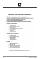
WebNet User’s Guide
IO Technologies A/S
Version 2.0
15 august 2003
2
WebNet User’s Guide
How to get started
Your new WebNet must be assigned a valid IP address before you can use it.
This document describes how to do it, using the ARP command. (For more
information consult section 1 in the WebNet System Manual).
Assume your PC is assigned an IP address on the 192.168.26.x subnet, and your
WebNets MAC address is 00:D0:C8:00:1A:BC (printed on a white sticker
on the WebNet module). To assign IP address 192.168.26.7 to the WebNet do the
following:
1. Connect the WebNet to your Ethernet and apply power.
2. Type arp -s 192.168.26.7 00-D0-C8-00-1A-BC in a command prompt on your PC (See the WebNet System Manual).
3. Type ping 192.168.26.7 , and when the WebNet responds to the
ping command, it has been assigned the IP address.
4. Type arp -d 192.168.26.7 to remove the static entry from the PCs
arp table. The WebNet is assigned a valid IP address and ready for use
5. Use a standard web browser to open the network page:
http://192.168.26.7. To explore all the included features use admin
as user and admin as password when you access secure files.
Note: If your browser does not find your WebNet, make sure its configured to use
your LAN, not a Modem. If you connect through a proxy server - e.g. win-proxy
- you must disable use of proxy in your browser settings.
To get hardware and software documentation for the WebNet module and WebPIC
or WebRJS interface boards, please visit our website at
http://webnet.iotech.dk.
WebNet User’s Guide
3
Contents
1 Introduction
9
1.1
What is the WebNet? . . . . . . . . . . . . . . . . . . . . . . .
9
1.2
The WebNet Start kit . . . . . . . . . . . . . . . . . . . . . . .
9
1.3
About this Manual . . . . . . . . . . . . . . . . . . . . . . . .
10
2 Unpacking
11
2.1
Package Contents . . . . . . . . . . . . . . . . . . . . . . . . .
11
2.2
The WebNet DIMM Module . . . . . . . . . . . . . . . . . . .
11
2.3
The WebRJS-PIC Adapter Board . . . . . . . . . . . . . . . . .
12
2.4
Connecting the boards . . . . . . . . . . . . . . . . . . . . . .
14
3 Installation
3.1
16
Connecting to the Network . . . . . . . . . . . . . . . . . . . .
16
3.1.1
Connecting to a hub . . . . . . . . . . . . . . . . . . .
16
3.1.2
Connecting to a network switch . . . . . . . . . . . . .
16
3.1.3
Connecting directly to the computer . . . . . . . . . . .
16
3.2
Applying power . . . . . . . . . . . . . . . . . . . . . . . . . .
17
3.3
Assigning an IP Address . . . . . . . . . . . . . . . . . . . . .
17
3.3.1
Auto-IP – the details . . . . . . . . . . . . . . . . . . .
17
3.3.2
Auto-IP – how to assign an IP address . . . . . . . . . .
18
Browsing the WebNet . . . . . . . . . . . . . . . . . . . . . . .
19
3.4
4 Configuration
4.1
4
21
Access Control . . . . . . . . . . . . . . . . . . . . . . . . . .
21
4.1.1
21
Setup of web users . . . . . . . . . . . . . . . . . . . .
WebNet User’s Guide
5
6
7
4.1.2
FTP to the WebNet . . . . . . . . . . . . . . . . . . . .
21
4.1.3
Setup of FTP users . . . . . . . . . . . . . . . . . . . .
24
4.2
Network Settings . . . . . . . . . . . . . . . . . . . . . . . . .
25
4.3
Software Installation . . . . . . . . . . . . . . . . . . . . . . .
27
4.4
Remote Access . . . . . . . . . . . . . . . . . . . . . . . . . .
28
4.5
Serial Lines . . . . . . . . . . . . . . . . . . . . . . . . . . . .
29
Monitoring and Statistics
31
5.1
Console output . . . . . . . . . . . . . . . . . . . . . . . . . .
31
5.2
File System Information . . . . . . . . . . . . . . . . . . . . .
31
5.3
Network Quality . . . . . . . . . . . . . . . . . . . . . . . . .
31
5.4
Socket Status . . . . . . . . . . . . . . . . . . . . . . . . . . .
33
5.5
Test and Service . . . . . . . . . . . . . . . . . . . . . . . . . .
34
5.5.1
Hardware Tests . . . . . . . . . . . . . . . . . . . . . .
35
5.5.2
Firmware Upload . . . . . . . . . . . . . . . . . . . . .
35
Tools
37
6.1
Adjust Real Time Clock . . . . . . . . . . . . . . . . . . . . .
37
6.2
Edit File . . . . . . . . . . . . . . . . . . . . . . . . . . . . . .
38
6.3
Interface Controller Update . . . . . . . . . . . . . . . . . . . .
38
6.4
Scheduled Script Control . . . . . . . . . . . . . . . . . . . . .
39
6.5
WebScript Debugging Tool . . . . . . . . . . . . . . . . . . . .
39
Uploading and Running Scripts
41
7.1
What are Scripts For? . . . . . . . . . . . . . . . . . . . . . . .
41
7.2
Types of Web Pages . . . . . . . . . . . . . . . . . . . . . . . .
41
7.3
Example Script . . . . . . . . . . . . . . . . . . . . . . . . . .
42
WebNet User’s Guide
5
7.4
Running the Script . . . . . . . . . . . . . . . . . . . . . . . .
42
7.5
Debugging Scripts . . . . . . . . . . . . . . . . . . . . . . . .
43
8 WebNet as an RS232 Gateway
44
8.1
Loopback example . . . . . . . . . . . . . . . . . . . . . . . .
44
8.2
Application on the WebNet or on the PC? . . . . . . . . . . . .
45
8.3
Application on the PC . . . . . . . . . . . . . . . . . . . . . . .
46
8.4
Application distributed on the WebNet and the PC . . . . . . . .
46
8.5
Architecture Considerations . . . . . . . . . . . . . . . . . . .
47
9 WebNet with GPRS Modem
49
9.1
Service Access . . . . . . . . . . . . . . . . . . . . . . . . . .
49
9.2
Installation . . . . . . . . . . . . . . . . . . . . . . . . . . . .
50
9.2.1
Hardware installation . . . . . . . . . . . . . . . . . . .
50
9.2.2
Webnet Configuration . . . . . . . . . . . . . . . . . .
51
9.3
Troubleshoting (from LAN) . . . . . . . . . . . . . . . . . . .
51
9.4
Advanced Settings . . . . . . . . . . . . . . . . . . . . . . . .
52
9.4.1
Connection notification by SMS . . . . . . . . . . . . .
52
Using WebNet as GPRS Access Router . . . . . . . . . . . . .
52
9.5
A How To Get Started
53
B WebNet IP configuration
54
B.1 Secure Restart . . . . . . . . . . . . . . . . . . . . . . . . . . .
54
B.2 Your ARP table . . . . . . . . . . . . . . . . . . . . . . . . . .
55
B.3 AutoIP Feature . . . . . . . . . . . . . . . . . . . . . . . . . .
56
C References
6
57
WebNet User’s Guide
List of Figures
1
The WebRJS module with the WebNet module inserted . . . . .
10
2
The WebNet DIMM module . . . . . . . . . . . . . . . . . . .
12
3
The component side of the WebRJS-DCE board . . . . . . . . .
13
4
The WebNet module is being inserted into the WebRJS module .
14
5
The WebNet module inserted into the WebRJS-PIC module . . .
15
6
The WebNet home page of version 1.93. . . . . . . . . . . . . .
20
7
Setup of access rights for web users . . . . . . . . . . . . . . .
22
8
A list of the most useful ftp commands . . . . . . . . . . . . . .
23
9
A list of the most important directories on the WebNet . . . . .
23
10
Setup of access rights for the FTP users . . . . . . . . . . . . .
24
11
The configuration page for network settings . . . . . . . . . . .
26
12
The System Maintenance Page, for Software installation . . . .
28
13
Setup page for the Device Sharing service . . . . . . . . . . . .
29
14
Configuration box for the serial lines . . . . . . . . . . . . . . .
30
15
The File System Status Page . . . . . . . . . . . . . . . . . . .
32
16
The Socket Status Page . . . . . . . . . . . . . . . . . . . . . .
33
17
The Test and Service Page . . . . . . . . . . . . . . . . . . . .
34
18
The Real Time Clock Setup Page . . . . . . . . . . . . . . . . .
37
19
The PIC Update Page . . . . . . . . . . . . . . . . . . . . . . .
38
20
The WebScript Debugger Tool Page . . . . . . . . . . . . . . .
39
21
Example script displaying the TCP/IP configuration . . . . . . .
42
22
Principle of the loopback example . . . . . . . . . . . . . . . .
44
23
Example of a WebNet architecture . . . . . . . . . . . . . . . .
48
24
Examples on operator specific settings . . . . . . . . . . . . . .
49
WebNet User’s Guide
7
25
8
DCE Cable . . . . . . . . . . . . . . . . . . . . . . . . . . . .
50
WebNet User’s Guide
1
1.1
Introduction
What is the WebNet?
The WebNet is a small electronic device, capable of serving as a gateway between
another electronic device and an ethernet network – for instance an intranet or the
Internet. The WebNet can connect to other electronic devices via e.g. its RS-232
interface.
The user interface of the WebNet consists of a number of web pages contained
in the device and presented by its built-in web server. A standard web browser is
used to view and browse these pages.
Once connected to the user’s RS-232 device, further user interface web pages can
easily be developed by means of the built-in WebScript programming language.
Thus, within short time, the user’s device can be configured and monitored with
a standard web browser as the only necessary application.
1.2
The WebNet Start kit
The WebNet itself is a “sub-credit-card” sized DIMM module, which makes it
suitable as an add-on module for another device. For the benefit of this module,
two different start kits, a “WebRJS-DCE” and a “WebRJS-PIC” adapter board is
supplied. The start kits makes it possible to connect power, ethernet and RS-232
via standard sockets. The WebRJS-DCE and the “WebRJS-PIC” boards can thus
be considered “motherboards” for the WebNet, with the specialized purpose of
providing RS-232 connectivity. Figure 1 shows the WebRJS module with the
WebNet module inserted. The “WebRJS-PIC” adapter board contains an additional microcontroller, PIC16F876. The microcontroller opens possible connections to a wide range of different hardware interface types. All I/O ports of the
microcontroller is accessable through a connector on the PCB.
WebNet User’s Guide
9
Figure 1: The WebRJS module with the WebNet module inserted
1.3 About this Manual
The purpose of this manual is to make the new WebNet owner acquainted with
the WebNet start kit and get started using it1 . First, in section 2 we unpack and
identify the parts of the start kit. Then, in section 3 we install the unit and connect
to it with a web browser. Sections 4, 5 and 6 are a tour round the various
configuration and monitoring/statistics pages of the WebNet. In section 7 we
look at the basics in writing and running scripts for making dynamic web pages.
In section 8, we try to get a “hole through” to the RS-232 interface. Section C
contains references to further information.
Updated information, documentation and service can be found on the IO Technologies’ WebNet home page [9] http://webnet.iotech.dk. See also IO
Technologies’ home page [8]
http://www.iotech.dk for information on other services offered by IO
Technologies.
1 Most of the information in this manual applies to version 1.93, or later, of the WebNet software.
Functionality, user interface and specifications may change in later versions.
10
WebNet User’s Guide
2
Unpacking
2.1
Package Contents
The WebNet Start kit consists of the following items:
• The WebNet DIMM module.
• One of the following:
1. The WebRJS-DCE adapter board.
2. The WebRJS-PIC adapter board with the LED demo board.
• An AC adapter (240V/50Hz).
• An ethernet UTP Cat. 5 interface cable (2 m) for connection to an ethernet
hub.
• A crossed ethernet interface cable for direct connection to a workstation
(red colored).
• An RS-232 DB9BU interface cable (1,8 m)
• WebNet User’s Guide.
2.2
The WebNet DIMM Module
The front side of the WebNet module is the one with the IC with the white label
on it. On Figure 2, the numbers indicate:
1. The ethernet status LED’s
2. Battery clip for real-time clock backup battery (from WebNet rev. 4). Battery is not included in the start kits.
3. Label with ethernet MAC-address (hardware address)
4. Connector
WebNet User’s Guide
11
Figure 2: The WebNet DIMM module
The status LED’s on the board indicate:
Green Server activity level (“heartbeat”)
Red Internet activity — input/output via the network.
Yellow Network activity — general activity on the attached ethernet.
2.3 The WebRJS-PIC Adapter Board
The WebRJS-PIC adapter board has a component side and a side with the connector for the WebNet DIMM module. The component side is shown on Figure 3,
and the numbers indicate the following:
1. RS-232 socket (DB9 female)
2. Reset button
12
WebNet User’s Guide
3. Ethernet status LED’s (replicated)
4. Ethernet RJ45 socket
5. Power socket (6,5-7,5V DC)
6. Debug button
7. PIC16F876 microcontroller
Figure 3: The component side of the WebRJS-DCE board
WebNet User’s Guide
13
2.4 Connecting the boards
The WebNet DIMM module is inserted into the connector on the WebRJS board,
at an angle of approx. 20 degrees. It is pushed gently into the socket, and when
the connector on the WebNet module cannot be seen anymore, the module is
pushed towards the WebRJS board until it “clicks”. The modules are now connected.
Figure 4 show the connector side of the WebRJS board, with the WebNet module being inserted. Figure 5 show the WebRJS board with the WebNet module
properly inserted.
Figure 4: The WebNet module is being inserted into the WebRJS module
14
WebNet User’s Guide
Figure 5: The WebNet module inserted into the WebRJS-PIC module
WebNet User’s Guide
15
3 Installation
3.1 Connecting to the Network
Besides the WebNet Start Kit, you need a computer with TCP/IP and a web
browser installed on it. The computer must be equipped with a network adapter.
You can either connect the WebNet Start Kit directly to the network adapter on
the computer, or you can connect it to a network hub or switch (not recommended
before an IP address is assigned to the WebNet) on the local area network.
3.1.1 Connecting to a hub
When connecting to a hub to which the computer is attached, the “straight” network cable supplied with the Start Kit is used. Make sure that the hub is capable of running 10Mbps. Old hubs only run 10Mbps and many new dual-speed
hubs automatically detects the speed and run either 10 or 100Mbps (or is able to
switch packets between devices of different speeds), but some new hubs only run
100Mbps. The only solution in the latter case is to replace the hub.
Also make sure that the WebNet and the computer are on the same segment of
the LAN, that is, no routers or bridges are in between the two devices. Hubs or
switching hubs are OK.
3.1.2 Connecting to a network switch
Connecting the WebNet to a network switch, before an IP-address is configured,
is not recommended. Some network switches might filter out packets addressed
to “unknown” MAC addresses. Once the WebNet is properly configured, there
are no problems in connecting it to a network switch. Use the same network cable
as when connecting to a hub.
3.1.3 Connecting directly to the computer
To connect the WebNet directly to the computer, a “crossed” network cable is required (use the red colored one supplied with the Start Kit). The network adapter
in the computer must be capable of running 10Mbps.
16
WebNet User’s Guide
In case of problems, configure the network adapter to 10Mbit link speed or “autosense” – 100Mbit will not work. Notice that the link speed cannot be set on all
types of network adapters.
For Windows computers the setting would appear (if applicable) in
Control Panel -> Network -> (Adapter name)
-> Properties -> Advanced -> Link speed
The crossed network cable is connected to the network adapter in the computer
and to the WebNet.
3.2
Applying power
The AC adapter is connected to the power socket on the WebRJS board and power
is switched on. The LED’s should start flashing after a few seconds, and after an
additional few seconds the unit has finished booting.
3.3
Assigning an IP Address
A WebNet module is, from the factory, configured to run in a so-called “AutoIP mode”. The technical details of assigning an IP-address with Auto-IP mode
are explained in section 3.3.1 below, but you may want to skip that section and
proceed to the description of the necessary steps to assign the IP address, in
section 3.3.2.
3.3.1
Auto-IP – the details
The board has, from the factory, a hardware (MAC) address, but no IP-address.
Auto-IP makes it listen to network packets for its own MAC address, and when
the first IP-packet for that MAC address comes in, it takes the receiver-IP address
from that packet and uses that as its IP address. To be able to send such a packet,
an entry is added to the arp table of the computer, where the desired IP address is
associated with the MAC address. Thus, to assign the WebNet an IP-address, the
following steps should be carried out:
WebNet User’s Guide
17
3.3.2 Auto-IP – how to assign an IP address
The steps described here apply to Windows machines, but a similar procedure is
possible on e.g. UNIX machines. Check your local flavour of arp by typing
arp -? in a command prompt, in case of problems.
In this example, the desired IP address is 192.168.4.10 and the MAC address is
(from the label on the WebNet module) 00-d0-c8-00-01-0d.
1. Open a command-line interpreter (DOS-prompt)
2. Make a static entry in the arp table by entering the command:
arp -s 192.168.4.10 00-d0-c8-00-01-0d
3. Ping the WebNet board:
ping 192.168.4.10
The ping command should result in 4 successive positive answers each starting
with: Reply from 192.168.4.10. If something has gone wrong, the answers start
with “Request timed out”.
If the pings responded successfully, the IP address is now assigned. Otherwise,
check the following list of possible sources of error:
• Are the WebNet and the PC on the same network segment?
• Is the connected hub/switch or network adapter capable of running 10Mbit?
• Did you type the correct MAC/IP addresses in the arp-command? Check it
with
arp -a (lists all arp entries)
• Is the unit properly connected (check the link indicator LED on the hub or
network adapter that the board is connected to)?
• Did you wait approx 10 seconds after power-on before issuing the ping?
• Did you use the right cable (see section 3.1.3).
The auto-IP is typically the way to assign an IP address the first time. Setting
the IP address permanently is explained in section 4.2. The IP configuration is
detailed in appendix B.
18
WebNet User’s Guide
3.4
Browsing the WebNet
The web server contained in the WebNet module is always active. Thus, you can
browse its contents as soon as you have assigned the module its IP address.
Simply type the IP address of the WebNet in the “location” field (where you
normally type URL’s manually) of your browser, and press ‘enter’.
If you are on a network with a proxy web-server (a typical company LAN) you
may experience that the browser “hangs” when trying to connect to the WebNet.
You probably have to adjust your “proxy exceptions”, so as not to redirect your
WebNet-traffic to the proxy-server. In Internet Explorer, proxy exception settings
are found in:
Options -> Internet settings
-> Connections -> LAN Settings
-> Proxy Server/Advanced -> Exceptions
In Netscape, they are found at
Edit -> Preferences -> Advanced -> Proxies
-> View -> Exceptions
In the list of exceptions, add the IP address of the WebNet module. When all is
set up right, the home page of the WebNet appears:
Now would be a good time to read the first 5 bullets on the page, which contain
lots of useful information about the WebNet: Its background, its HW and SW
architecture, and descriptions of lots of features, among many other things.
WebNet User’s Guide
19
Figure 6: The WebNet home page of version 1.93.
20
WebNet User’s Guide
4
Configuration
Configuration of the WebNet module is done via the configuration pages accessible from the WebNet home page described above, under the headline “System
Configuration”. The sections below each describe one such configuration page.
To access these pages, a username and password should be entered. By default,
these are “admin” and “admin”, but they should be changed – see how in section 4.1 below.
4.1
Access Control
Access control can be implemented at a more or less fine-grained level. By default, an “admin” user exists, with the password “admin”. The “admin” password
can be changed in the access control page. The admin user has access to the web
pages in the “setup” section of the web page area – that is, the web pages we are
accessing right now. Also, admin has full ftp access to the file system, with all
privileges (see section 4.1.2 for more information on FTP). An additional user,
“anonymous” also exists, with the password “anonymous”. This user has readonly ftp access to the web page hierarchy. Other users, perhaps with limited
privileges, can be added by means of the two links on the bottom of the access
control page.
4.1.1
Setup of web users
Web access to certain file trees can be limited to certain hosts and be guarded
by username/password protection. For each file tree, the root directory name is
entered, and possibly a host name (‘*’ for any host). A number of users can then
be created, with associated passwords. One of these username/password pairs
has to be entered to access a page in the given file tree.
4.1.2
FTP to the WebNet
FTP (“File Transfer Protocol”) is used to read and write files from/to the WebNet,
for instance to upload scripts and web pages. You need an FTP client on the PC,
and Windows 95/98/NT has a command-line FTP client built in. Alternatively,
WebNet User’s Guide
21
Figure 7: Setup of access rights for web users
lots of freeware FTP clients exist, with more user-friendly file manager-like interfaces.
Most new internet browsers support FTP. The address (URL) is here of the form:
ftp://admin:[email protected].
Netscape is able to upload files using the File menu. Microsoft Internet Explorer
5.0 and newer allows copy and paste between your local Windows machine and
the WebNet.
Connecting to the WebNet can be done by opening a DOS-prompt and issuing
the command:
ftp 192.168.4.10
You are then prompted for a username and a password, and you can use “admin”/”admin” to gain full access.
A list of the most useful ftp commands is provided in Figure 8.
Doing an “ls” after connecting with FTP will show a number of files and directories. The most important are shown in Figure 9.
22
WebNet User’s Guide
dir or ls
!dir
cd dirname
lcd
dirname
put
filename
get
filename
bin
ascii
exit
list files in current working directory on the server
list files in current working directory locally (on the
client)
change directory ( cd ..
to go backwards) on the
server
change directory ( lcd .. to go backwards) locally
(on the client)
upload a file to the server
download a file from the server
set transfer mode to “binary” (8 bit transfer)
set transfer mode to “ascii” (7 bit transfer)
Quit ftp session
Figure 8: A list of the most useful ftp commands
WebNet
autoexec
cgi-bin
etc
webpages
The “operating system” itself.
Configuration file describing which scripts to run at
startup.
Root directory of dynamic webpages (WebScript scripts)
Directory for configuration files
Root directory for static webpages (html pages)
Figure 9: A list of the most important directories on the WebNet
WebNet User’s Guide
23
4.1.3 Setup of FTP users
Figure 10: Setup of access rights for the FTP users
The privileges of the two FTP users “admin” and “anonymous” can be set up
on the “Configure FTP Access” page. For each user there is a Password field
and a Root directory field. The password field is self-explanatory, and the root
directory field contains a path to the directory that the user sees when he logs in
via FTP. The user cannot “cd” backwards (towards the root) from this directory.
Each user is also assigned a number of privileges: “Get” is the ability to read files
from the WebNet (download), “Put” is the ability to write files (upload), “Delete”
is the ability to delete files from the WebNet, “Mkdir” is the ability to create new
directories on the WebNet and “Rmdir” is the ability to remove directories on the
WebNet. In Figure 10, the default settings are shown.
24
WebNet User’s Guide
4.2
Network Settings
The configuration form for the Network settings initially contains only a small
number of entries, but can be expanded to show all possible network settings.
The example in Figure 11 shows the full form, which is accessed by pressing the
link “Click here to show advanced settings”. For more elaborate explanations of
the notions briefly described in this section, please consult the TCP/IP networking literature (e.g. [1], [7]). The local network administrator should be able to
provide the values for the different settings.
DHCP, RARP and AutoIP are ways to obtain network settings automatically at
boot time. Often, a DHCP server exists on the network, so probably this method
of configuration should be used.
It is configurable whether the automatically (from DHCP, e.g.) or the manually
entered configurations should be effective.
If automatic setup of network settings are used, the local network administrator
should be able to inform You which IP address is assigned to the WebNet.
All network settings can be set manually:
IP address is the identification of the WebNet on the TCP/IP network. Be sure it
is a valid, vacant address, supplied by the network administrator.
Subnet mask specifies how much of the IP address describes the host address
and how much describes the network address, for routing purposes.
Default gateway is the IP address to forward packets to, when their address is
not within the network described by the IP address / Subnet mask combination.
The gateway will know where to send them.
Domain is the name of the DNS domain that the WebNet belongs to. Nameserver is the IP address of a server in that domain, that does name/IP translations,
aka. a DNS server. For further reading about DNS, see [4].
Hostname is the DNS name of the WebNet. When the WebNet has been named,
be sure the name is inserted in the DNS server (the network administrator’s job).
Timeserver is the IP address of a server that runs a time-service, for setting of
the clock in the WebNet.
SMTP server is the IP address of a server running mail server (SMTP, Simple
Mail Transfer Protocol, see e.g. [2] for more information) software, for forward-
WebNet User’s Guide
25
Figure 11: The configuration page for network settings
26
WebNet User’s Guide
ing mails from the WebNet to the proper recipient.
The PPP Protocol settings should be set if TCP/IP communication is done over
a serial device, e.g. a modem connected to the RS-232 port.
The Serial device is chosen from one of “none”, “PIC”, “SP0” or “SP1”. The
“PIC” entry is only useful on WebRJS boards equipped with a PIC controller.
The “SP0” and “SP1” entries are the two serial ports. On the WebNet Start Kit
the accessible RS-232 port is SP0, so that is the only valid selection (besides
“none”).
Local IP address is the address of the WebNet module and Remote IP address is
the address of the TCP/IP node in the other end of the serial connection. Note that
the local IP address is not the same as the “IP address” described above. When
PPP is used, the WebNet becomes “multi-homed”, that is, it has two TCP/IP
interfaces: The ethernet interface and the serial interface. The two interfaces
must have different IP addresses. The local PPP address should be reachable
from the equipment in the other end of the serial connection.
PAP username and PAP password are for authentication with the remote node,
and should be set up in correspondence with the settings on the remote node.
When the desired changes have been entered, the “Save” button is pressed, and
the user is given the possibility to reboot. A reboot is necessary for the changes
to take effect.
The “Revert” button clears the form and re-inserts the values of the present configuration.
4.3
Software Installation
Software updates/installation on the WebNet module is done by transferring special archive files to the WebNet. This is done from the “Install software” page,
see Figure 12. The archive file, which may be located on the computer that the
WebNet is browsed from or on a floppy disk in its floppy drive, is located with the
“Browse” button. Pressing “Continue” afterwards transfers the file to the WebNet
module. The transfer can take minutes, depending on the size of the archive file
and the network speed.
Archive files can be found on I/O Technologies’ WebNet home page [9]:
WebNet User’s Guide
27
Figure 12: The System Maintenance Page, for Software installation
http://webnet.iotech.dk
Choose the “download” section, and then the “Firmware and standard applications” link. Here, a number of zip files exist, each containing a number of applications to try out.
Unzip the files with e.g. WinZip and read any read.me or readme.txt
files within the archives for installation instructions. WinZip can be obtained
from http://www.winzip.com. Once the standard application is installed
on the WebNet, it is accessed through a new link on the “Installed demonstration
software” page.
4.4 Remote Access
Device sharing is used e.g. when access to a serial resource is needed via the
ethernet interface, from a terminal program. A “mapping” is set up, where a serial
device is associated with a TCP/IP port. Thus, you can connect via a terminal
emulator or telnet application via device sharing to a serial device, send data to it
from the keyboard and read the responses.
28
WebNet User’s Guide
Figure 13: Setup page for the Device Sharing service
Figure 13 shows the setup parameters for device sharing. The serial devices can
be the PIC controller (if that exists) or one of the serial ports, “SP0” or “SP1”.
The server TCP port is the port on the WebNet that a TCP/IP host should connect
to, in order to reach the selected serial port. An idle timeout can be defined, where
0 means no timeout.
4.5
Serial Lines
The WebNet board contains 2 serial lines, but only one is physically available
at the WebRJS board – the primary serial line. On the page “Configuring serial
devices”, the only valid choice is thus “[sp0] Primary Serial Line”. The configuration page for each serial line looks like in Figure 14. In the first input box,
the baud rate (bits per second) is chosen between 300, 1200, 2400, 4800, 9600,
19200, 38400, 57600 and 115200 bits per sec.
In the next box the “mode” is selected – how many bits, parity on/off and the
number of stop bits. The choices are a number of combinations, like 8N1 , where
the 8 is the number of bits, the N is “no parity” (alternatively “O” for “Odd” or
“E” for “Even” parity), and the 1 is the number of stop bits.
The last box determines the type of flow control – none, hardware, RS-485 or
Xon/Xoff.
WebNet User’s Guide
29
Figure 14: Configuration box for the serial lines
30
WebNet User’s Guide
5
Monitoring and Statistics
The WebNet contains a number of useful monitoring and statistics tools. These
are accessed from the WebNet home page, under the headline “Monitoring and
Statistics”. The sections below each correspond to a link in that section of the
home page.
5.1
Console output
The console is where the WebNet outputs status and debugging information. As
the WebNet does not have a physical output device, the console can be reached
in one of two ways: Either with a terminal (or terminal emulator) connected to
the RS-232 port of the WebNet, or with a TCP-connection to port 911. On the
console output page you will find a Java applet that connects to this port and
displays its output. Only one connection can be made to this port, so only one
person can watch the debug output at the same time.
5.2
File System Information
The status of the file system can be checked with the link “File System Information” – see Figure 15. It tells the names and open-mode of any open files, the
total disk size, and the number of used, free, and free but not reclaimed blocks.
The size of one block is 510 bytes.
If you experience problems with the file system running full, you may want to
check the logging settings. Log files can grow fast if the system is busy.
5.3
Network Quality
“Pinghost” is a simple way of indicating the quality of a network connection in
terms of reliability and latency. It measures the success/failure rate, the maximum
round-trip time and the average round-trip time of ping packets. The results of
these measurements are plotted in a graph, which is updated every 2 min. When
the graph is completed, it shows statistics for a 24 h. period.
WebNet User’s Guide
31
Figure 15: The File System Status Page
32
WebNet User’s Guide
The host that “pinghost” should send its ping packets to is set up in the PingHost
field below the graph. It is necessary to boot the WebNet after setting up the
PingHost.
The statistics say nothing about data throughput. A simple throughput test can
be performed by transferring a relatively large file to the WebNet via FTP. Most
FTP client programs tell the average transfer rate after the transfer.
5.4
Socket Status
On the Socket Status page, listening server endpoints (passive sockets or server
sockets) and active network connections can be checked:
Figure 16: The Socket Status Page
In the example in Figure 16, three passive sockets exist: (#1) Port 80 (www), (#2)
port 21 (ftp) and (#12) port 1010 (WebNet Device Sharing). These sockets wait
WebNet User’s Guide
33
for connection requests from clients, and then create new active sockets. Two
active connections exist, one (unnumbered) to the telnet server port 911 from a
host with IP no. 192.168.2.58, and one (#4) to the web server from a host with
IP no. 192.168.2.58. There are unfinished TCP connections (#8) web connection
to a host with IP no. 192.168.2.52, (#5 and #6) web connections to a host with
IP no. 192.168.2.58. Finally, there is an unnumbered system connection to the
DHCP server at IP address 192.168.2.53.
5.5 Test and Service
Figure 17: The Test and Service Page
The Test and Service page (Figure 17) has two main purposes: To provide a
number of hardware tests, in case you suspect that the hardware is defect, and to
34
WebNet User’s Guide
make it possible to boot the WebNet and restart in “maintenance FTP mode”, for
firmware upload:
5.5.1
Hardware Tests
The hardware tests are only used if the WebNet behaves in an unexpected manner.
• Problems with files being corrupted, files disappearing and the like can be
diagnosed with the “Flash test”.
• Overall responsiveness of the system can be verified with the “LED’s test”.
• Seemingly inexplicable behavior can be caused by defective RAM. The
two RAM tests “RAM test 1” and “RAM test 2” cover different aspects of
RAM test.
5.5.2
Firmware Upload
A complete firmware replacement can be done by uploading a flash disk image
file to the WebNet. As the existing flashdisk contents are deleted and then replaced, all settings must be restored afterwards.
Upload is done via a minimal implementation of FTP (µ-FTP) that resides in a
separate sector of the WebNet Flash, not on the flashdisk itself. To enable this
type of FTP, the WebNet must be booted with the µ-FTP button on the “Test and
service” page. After approx. 7 seconds, the WebNet is ready to receive a new
flash image. Assuming the flash image is in a file called webnet.bin on a
floppy in drive A on the PC, the steps are as follows:
1. Open a DOS-prompt and start the FTP-client: ftp 192.168.4.10
NOTE: Only text based FTP-clients works with µ-FTP (i.e. not through
browser).
2. Set the ftp-client to “binary transfer” with the command bin .
3. Delete the existing flash image with the command del flash
(this command takes a while to return).
WebNet User’s Guide
35
4. Transfer the new image with the command put A:\webnet.bin’
(the destination file is implicitly the flash file). The transfer may take up to
a few minutes dependent on the network quality.
5. µ-FTP may reboot the WebNet from the new flashdisk with the command:
quote BOOT .
6. Once the WebNet has started, close the FTP-client using the command
bye . The Auto-IP feature now detects the IP-address (through the AutoIP feature). As mentioned, all settings should now be restored.
36
WebNet User’s Guide
6
Tools
The “Tools” section contains a number of useful tools and utilities for making
more advanced configuration changes to the WebNet.
6.1
Adjust Real Time Clock
The real time clock can be adjusted to be in synch with the PC connecting to it, or
to a manually entered time/date – see Figure 18. Notice that only WebNet boards
with a battery inserted in the battery clip can keep the correct time/date settings
between reboots (from WebNet rev. 4).
Figure 18: The Real Time Clock Setup Page
After choosing to synchronize or after having set the date and time fields manually, the “Adjust” button is pushed to make the changes effective.
WebNet User’s Guide
37
6.2 Edit File
A simple editor is provided, to make it possible to edit a file locally on the server,
without having to download it to a PC, edit it and upload it again. The filename
is entered into the first textbox, the “load” key is pressed and the file appears in
the editor. After editing, “save” is pressed and the file is saved again. The size of
the editor can be changed by means of the resize key and the X and Y fields, and
the original contents of the file can be restored by means of the “Revert” key.
NOTE: Be carefull when updating critical files on the WebNet.
Access to the editor is password protected setup by the page that is described in
section 4.1.
6.3 Interface Controller Update
This function only applies to WebNet on PIC enabled boards. The software for
the PIC processor can be transferred to the PIC by means of the form shown in
Figure 19.
Figure 19: The PIC Update Page
The program file must be of the Intel hex format (the same format as created by
the Microchip assembler; “mpasm.exe”).
The hex-file, which may be located on the computer that the WebNet is browsed
from or on a floppy disk in its floppy drive, is located with the “Browse” button
and is then uploaded to the WebPIC’s PIC controller with the “Upload” button.
The hex-file is now being uploaded and parsed by the PIC programming software.
The actual PIC type is detected, and two new buttons appears. To compare the
38
WebNet User’s Guide
content of hex-file with the program which is already programmed into the PIC,
press the “Compare” button. To program the the content of the hex-file into the
PIC, press the “Program” button.
More information on the WebPIC and programming the PIC can be found in [9]
6.4
Scheduled Script Control
The “Scheduled Script Control” page shows a number of scripts that are triggered
by certain events. This can be considered an advanced parameter, and should not
be adjusted, unless working with scheduled or event-driven scripts [3].
6.5
WebScript Debugging Tool
When getting acquainted with the WebScript scripting language, or debugging
Internet applications, the interactive debugging tool comes in handy.
Figure 20: The WebScript Debugger Tool Page
The layout can be seen in Figure 20. In the top window (“script”), script code is
typed/pasted directly in, and “submit” is pushed. The script is executed, and if
WebNet User’s Guide
39
nothing fails, the “output” window now contains the output from the script, and
the “stack” window contains what may be left on the stack.
The “verbose” switch enables listing of the CGI parameters and details about the
CGI query.
The procedure for uploading and running scripts is described in section 7, and
the WebScript scripting language is described in [3].
40
WebNet User’s Guide
7
Uploading and Running Scripts
This section deals with WebScript scripts, the built-in scripting language in the
WebNet. More details, both on CGI scripts in general and WebScript in particular, can be found in [3].
7.1
What are Scripts For?
Scripts are used in the WebNet to create dynamic web pages. Static web pages
are written purely in HTML [6], and their contents are thus constant between
accesses. Dynamic web pages are generated at access-time by a script, and can
thus present content that changes over time. The script executes on the server, and
can thus manipulate server resources and things that is connected to it – which is
interesting when the server is a WebNet connected to some appliance.
When the script is executed by the server, the script sends the output to the
browser connecting to it. Thus, the script’s job is to generate some meaningful
html code for the browser to display.
7.2
Types of Web Pages
Besides the purely static pages, we can distinguish between “read-only” dynamic
webpages and dynamic webpages with side-effects on the server:
A simple dynamic “read-only” web page typically contains a static “header” part
(html-header and whatever goes on the top of the page), a dynamic “contents”
part (the auto-generated part) and a static “footer” part (whatever goes on the
bottom of the page).
A dynamic web page with side-effects typically contains (among other things)
forms, and on the basis on data supplied by the user in these forms it runs different
code on the server, possibly changing items in a database, or controlling attached
hardware.
WebNet User’s Guide
41
7.3 Example Script
A simple script generating a dynamic read-only web page could look like in Figure 21 (similar to an example in [3]). The line numbers are for textual reference
only, they are not part of the code. The script lists the current TCP configuration:
1:
2:
3:
4:
5:
6:
7:
8:
(<html><head><title>WebScript test</title></head>) print
(Current TCP configuration) print
(<table>) print
etc /tcp get
{ exch (<tr><td>) print xprint
(<td> : <td>) print print (\n) print
} forall
(</table></body></html>) print
Figure 21: Example script displaying the TCP/IP configuration
Line 1 prints the necessary html header information and the title. Line 2 prints
the page headline. Line 3 starts the table definition. 4-7 is a loop that iterates over
the contents of the tcp directory (residing in the etc directory). For each entry it
starts a new table row, a new column, prints the parameter name, makes a new
column with a colon in it, makes a new column with the parameter value in it,
and finally prints a newline. In line 8, the table, the body part and the whole html
page are finished.
You can try this script by typing it into the WebScript debugging tool (see section
6.5). Otherwise you can type it into a file, upload it to the WebNet and run it
there – see section 7.4 below.
7.4 Running the Script
Scripts are either edited with the built-in editor (see section 6.2) or uploaded via
FTP. Suppose you have edited the script on the PC, in a file called c:\tcpsettings,
(the file extension conventions regarding WebScript files say that they have no
extension!) you do the following:
1. Connect via FTP from the PC to the WebNet: ftp 192.168.4.10
42
WebNet User’s Guide
2. Log in with username admin and password admin (unless you have
changed them)
3. Change directory to the cgi-bin directory, where the scripts reside:
cgi-bin
cd
4. Upload the file: put c:\tcpsettings tcpsettings
You can check that the file has arrived safely by typing dir , which shows the
files in the cgi-bin directory, with size information. When the script is located in
cgi-bin, you run it by typing in the URL:
http://192.168.4.10/setup/tcpsettings
The web page appearing should be the expected list of TCP/IP settings.
The setup part of the above url is a logical path that “points to” the cgi-bin
physical path on the WebNet. This is for historical reasons.
7.5
Debugging Scripts
Perhaps the script fails, probably meaning that you have made a typing mistake
somewhere in the script. You can then use the built-in editor to correct the mistake, instead of ftp’ing the script back on the PC, editing it, and uploading it
again. See section 6.2 for more information on the built-in editor.
If you are more in doubt about what went wrong, you may want to try the WebScript debugger described in section 6.5. You will have to copy/paste the code
into the debugger, and once you “submit” it, you will see the output in one window and the stack contents in another window. Often, errors in WebScript programs relate to errors in the order of elements on the stack, so this “stack dump”
can be a great help.
WebNet User’s Guide
43
8 WebNet as an RS232 Gateway
A very useful application of the WebNet is as a gateway between an ethernet
network and an RS232 equipped device. Many existing devices are presently
controlled via an RS232 connection, and by applying a WebNet to such a device,
it becomes Internet-enabled.
The user can then, e.g. read status information on a web page, and control the
equipment by activating web forms. The “intelligence” of the controlling system
can be placed either on the WebNet module or on the PC – pro’s and con’s of
each are described in section 8.2 below.
First, we describe a quick way to establish a “hole through” the RS232-ethernet
gateway, to see that it works.
8.1 Loopback example
We wish to establish a connection from the PC to the WebNet through the serial
line, and a connection “back” from the WebNet to the PC through the ethernet
connection – a loopback connection.
T e r m in a l
e m u la to r
P C
T e ln e t
a p p lic a tio n
S e r ia l IF
E th e rn e t IF
W e b N e t
M o d e m
e m u la tio n
S e r ia l IF
E th e rn e t IF
Figure 22: Principle of the loopback example
44
WebNet User’s Guide
The example requires a telnet application and a terminal emulator application on
the PC. Telnet is included in Win95/98/NT and is reached from the DOS prompt.
They also contain a terminal emulator called “Hyper Terminal”, which is found
under
start -> programs -> accessories -> communication
The following steps are carried out (We assume the PC already has network connection to the WebNet):
• A serial cord is connected to the WebNet RS232 port and to a free COMport on the PC (let us say COM2).
• The Terminal emulator is opened, and it is set up to connect directly to
COM2. (check that serial line settings correspond with those of the WebNet).
• The “Device Sharing” settings (on the WebNet home page) is setup to “serial port sp0”, “telnet port 1010”.
• A telnet session with the WebNet port 1010 is started, e.g. with the command telnet 192.168.4.10 1010 .
• Now, keystrokes entered in the terminal emulator should appear in the telnet application and vice versa.
Thus, the data entered “into” the RS232 interface is routed through the WebNet
and out to TCP/IP port 1010. Conversely, data sent to port 1010 of the WebNet
are routed to the RS232 interface.
8.2
Application on the WebNet or on the PC?
The system’s intelligence can be implemented either on the WebNet or on the PC
connected to it.
When the intelligence of the system is placed on the WebNet, some WebScript
code runs and interacts with the device continuously. The user can, at any time,
connect to the WebNet thus asking this code to generate a web page telling the
WebNet User’s Guide
45
device’s status. This may be useful whenever continuous interacting with the device is desirable (e.g. if data logging is needed) without a client being connected.
When the intelligence of the system is placed on the PC, a Java applet [5] is put on
the WebNet, which is then automatically uploaded to the browser upon connection. The Java applet can connect directly to the RS232 device and implement all
protocol handling, data processing and presentation. The user can view the status
of the device and control it, according to the capabilities of the protocol.
The PC can also run some dedicated application that communicates with the WebNet and interprets and presents the data from the device.
8.3 Application on the PC
The advantage of having the application run on the PC as a Java applet is that
more complex things can be done with a fairly small amount of code on the WebNet. For instance, graphical representations of data are easily coded in Java. Even
though the Java applet is kept small, its functionality can be complex because it
“links” with objects from the PC’s class library at runtime.
An applet is excecuted “inside” an HTML page. The browser fetches the HTML
page from the server, and the HTML page contains a reference to the applet. The
browser then fetches the applet from the server and runs it, sending its output to
a specific part of the browser screen.
As described in section 8.1 above, Device Sharing can be used to route TCP
traffic to/from a WebNet serial port. Thus, via a TCP connection from the applet
to the WebNet, the applet can reach the serial ports of the WebNet, and hence
communicate with an attached device. For instance, in a temperature surveillance
system, the WebNet is connected to a temperature sensor via the serial port. The
sensor outputs temperature data every 10 secs. to the serial port, from which it is
routed on to the ethernet interface. Here, an applet is listening for data, and plots
a point in a graph for each value received.
8.4 Application distributed on the WebNet and the PC
Often, it is necessary to split the application, so that some of the code runs on
the WebNet and some on the PC. Consider the above mentioned temperature
46
WebNet User’s Guide
surveillance system, but where the PC only connects once in a while and wants
to see the actual temperature, plus a temperature curve for the last few hours.
Then, the WebNet has to keep a history of the temperature, that it can send to
the PC upon connection, but the applet is still best suited to present the data. So
the data accumulation part of the application is put on the WebNet and the data
presentation part is put in the applet.
Also, electronic devices often use a more complex protocol than the above mentioned (where the sensor just outputs data at a regular interval) to communicate
over the serial interface. This protocol will then most likely be implemented in
the WebNet.
8.5
Architecture Considerations
The differences in architecture can be expressed by three questions, which should
be considered before designing a WebNet solution:
1. Does the WebNet process data or does it merely act as a gateway?
2. Does the WebNet generate dynamic web pages, serve an applet to the PC
or does the PC need to have a dedicated application?
3. Does the WebNet store a data history or not?
The answer to question 1 depends mainly on the “intelligence level” of the attached device. It may be useful to let the WebNet encapsulate very “raw” and
low-level protocols in something more high-level, for the applet or dynamic webpages to use.
Also, if the device should be able to deliver data when a PC is not connected,
some intelligence should be in the webnet software, buffering data for later reading by the PC.
The answer to question 2 depends mainly on the complexity of the data presentation needs. A dynamic webpage is suitable for presentation of simple textual/numeric data, while an applet is more suitable if graphical representation
is needed. A dedicated PC application will probably only be used if it existed
before the device was web-enabled, and just needs to be altered to use network
WebNet User’s Guide
47
communication instead of RS-232. New applications should be written as Java
applets.
The answer to question 3 simply depends on the need to recall a data history. If
a PC should be able to connect to the WebNet, check the data output during the
last e.g. 24 hours and then disconnect, the WebNet should store a data history.
Figure 23 is an example, showing a principal schematic of a setup with a device
(a sensor), a WebNet that does both protocol translation, data storage and applet
serving, and a PC. The PC displays the web page from the WebNet in its browser,
including the applet.
Please refer to [3] for a full introduction and reference to WebScript, as well as a
number of explained examples to get you started making WebNet applications.
Figure 23: Example of a WebNet architecture
48
WebNet User’s Guide
9
WebNet with GPRS Modem
The General Packet Radio System (GPRS) is a new service for passing data over
a mobile phone network. GPRS is a packet data overlay onto existing GSM
networks and provides faster data transfer rates (up to 56Kb/s for a class 10 modem), ”always on” connection, robust connectivity, broad application support,
and strong security mechanisms.
9.1
Service Access
To use GPRS with the WebNet, users specifically need:
• a GPRS modem with RS232 serial port interface. (A serial cable is usually
included)
• a subscription to a mobile telephone network that supports GPRS. The
subsciption will include information on the operators APN (Access Point
Name), username and password. A few examples are shown in figure 24
• a SIM card for the GPRS modem. This is usually provided with the subscription.
• a WebNet DTE add-on module with RS232 serial port interface.
Operator
TDC DK
Sonofon DK
Orange DK
Vodafone UK
GPRS APN
internet
[blank]
web.orange.dk
internet
Username
[blank]
[blank]
[blank]
web
Password
[blank]
[blank]
[blank]
web
Figure 24: Examples on operator specific settings
WebNet User’s Guide
49
9.2 Installation
Before starting the installation procedure make sure that...
• the WebNet firmware has been upgraded to verison 2.x or newer. Please
refer to chapter 5 for more information on how to upgrade the firmware.
• the SIM Pin Code is disabled. This can be done with a GSM mobile phone:
Replace the phones SIM card with the SIM card for the GPRS modem.
Use the phones menu to disable Pin Code Request in the Security Settings
menu. This procedure may vary depending on the type of mobile phone.
9.2.1 Hardware installation
• Mount the DTE add-on module to the Webnet.
• Attach the modem to the serial port on the DTE module with the serial
cable.
Note: For GPRS installation on a DCE Webnet the modem is attached to the onboard serial port [sp0] and a special cable is required. The cable is crossed so
that DCD connects to DTR (see figure 25).
Webnet DCE
Rx
Tx
RTS
CTS
DSR
DTR
–
–
–
–
–
–
–
GPRS modem
Tx
Rx
CTS
RTS
DTR
DCD
Figure 25: DCE Cable
50
WebNet User’s Guide
9.2.2
Webnet Configuration
Network Configuration Go to the ”Change Network Settings” menu (see figure
11):
• Leave the ”IP Routing” field ’off’ (default). However, if the the Webnet is used as GPRS Access Router (see section 9.5 ) ”IP Routing”
must be changed to ’nat’.
• Change ”Serial Device” to [sp1] (for serial port 1 on DTE module).
• Fill out ”Username” and ”Password” if these are required by the mobile network operator.
Serial Line Configuration Go to the ”Serial Lines” menu. Select ”[sp1] Auxiliary Serial Line”.
• Change ”Baud rate” to match the modem. (The Wavecom Fasttrack
modem default configuration is 9600 baud).
Please notice that the 2.0.a3 firmware does not perform auto scan for
modem baud rate.
For optimal performance with a class 2 modem configure both modem and SP1 to 34800 baud. Note: To configure your modem to
38400 baud, please follow the instructions in the modem manual.
Look for the command: "at+ipr=38400".
• Make sure that ”Serial Mode” is set to ’8N1’ and ”Flowcontrol” is set
to ’hardware’.
• In the ”Phone#” field enter the APN in quotation marks. For instance
if the APN is internet enter "internet". Leave the field empty
if the APN is [blank]
If the Webnet has been configured properly the assigned IP address on the GPRS
net is displayed in the ”Local IP Address” field in the ”Change Network Settings”
menu.
9.3
Troubleshoting (from LAN)
To help troubleshooting during and after GPRS installation, information from
the Webnet can be accessed from all serial ports: a console log on port 911 and a
WebNet User’s Guide
51
protocol trace on port 711.
E.g. from a windows command prompt enter following commands (assuming the
Webnets LAN IP is 192.168.4.10):
Console log (port 911):
telnet 192.168.4.10 911
Trace log (port 711):
telnet 192.168.4.10 711
9.4 Advanced Settings
9.4.1 Connection notification by SMS
The Webnet can send an SMS every time a connection to the GPRS net is established. In the ”Serial Lines”–”[sp1] Auxiliary Serial Line” menu enter the phone
number that receives the sms in the Alert# field. Leave the field empty to disable
this function.
9.5 Using WebNet as GPRS Access Router
A local network can be connected to the internet through a WebNet with GPRS
support when the Webnet has been configured to act as an access router. This
enables web browsing and emailing on a local PC, web cameras, web servers etc.
through the GPRS net.
To enable the Webnet GPRS Access Router change the ”IP Routing” field in the
”Change Network Settings” menu to ’nat’ and connect the Webnet to the local
ethernet network through the RJ45 connector.
52
WebNet User’s Guide
A How To Get Started
Your new WebNet must be assigned a valid IP address before you can use it.
This document describes how to do it, using the ARP command. (For more information consult section 1 in the WebNet System Manual). Assume your PC is
assigned an IP address on the 192.168.26.x subnet, and your WebNets MAC address is 00:D0:C8:00:1A:BC (printed on a white sticker on the WebNet module).
To assign IP address 192.168.26.7 to the WebNet do the following:
1. Connect the WebNet to your Ethernet and apply power.
2. Type arp -s 192.168.26.7 00-D0-C8-00-1A-BC in a command prompt on your PC (See section 1.2.2 in the WebNet System Manual).
3. Type ping 192.168.26.7 , and when the WebNet responds to the
ping command, it has been assigned the IP address.
4. Type arp -d 192.168.26.7 to remove the static entry from the PCs
arp table. The WebNet is assigned a valid IP address and ready for use
5. Use a standard web browser to open the network page:
http://192.168.26.7.
To explore all the included features use “admin” as user and “admin” as
password when you access secure files.
Note: If your browser does not find your WebNet , make sure its configured to use
your LAN, not a Modem. If you connect through a proxy server - e.g. win-proxy
- you must disable use of proxy in your browser settings.
To get hardware and software documentation for the WebNet module and WebPIC
or WebRJS i/f boards, please visit our website at
http://webnet.iotech.dk/Service.
WebNet User’s Guide
53
B WebNet IP configuration
Before you can configure your WebNet properly it must be assigned a valid IP address. This is done automatically if a DHCP, BOOTP, or RARP, server is present
in your network - or manually with the ARP command using the WebNet AutoIP
feature. Most products will only have AutoIP enabled by default, other features
must be enabled by configuration.
An IP address is a unique address for a host in a TCP/IP network. For manual
configuration (including AutoIP) it is therefore important for you to have a valid
IP address at hand, not used by anyone else on the network.
When WebNet is powered on it will immediately try to obtain an IP address from
a DHCP, BOOTP, or RARP server - if any of these services are enabled. Automatically assigned network parameters can be verified on the WebNet network
settings page.
B.1 Secure Restart
Most WebNet products have a button, or a jumper, which can be used to perform
a secure restart - which enables factory default settings during reboot. Factory
default settings have the AutoIP feature enabled, and you can then get access to
a WebNet with unknown network settings.
Secure restart is performed by:
1. pressing the control button (or jumper) about ten seconds, until the WebNet LEDs switches off. The LEDs may still flicker, but this just indicates
normal activity.
2. then release the button. The LEDs will flicking heavily, indicating that a
secure restart is in progress. A new button click during this period cancels
the secure restart.
3. After about five seconds of uninterrupted LED flickering the WebNet reboots and enters secure mode using its factory default settings.
The default settings will be active until the next reboot. During this period you
54
WebNet User’s Guide
can use the AutoIP feature to assign a temporary IP address to WebNet. This IP
address should be used to gain access and reconfigure WebNet properly.
B.2
Your ARP table
When your computer uses TCP/IP, e.g. has a Web Browser, it also has an ARP
table for your ethernet. The ARP table translates other units IP addresses to their
respective MAC addresses - which is required to communicate with other unit on
an ethernet network. ARP is a caching mechanism which normally does its job
silently in the systems background. It requires that other units on the network are
configured with IP addresses. The ARP tables can be monitered and manually
updated using the ’arp’ command available from a command prompt.
Show ARP help
Show ARP table contents
Add ARP perm. entry (Unix
and OS/2)
Add ARP temp. entry (Unix
and OS/2)
Add ARP entry (Windows)
Add ARP entry (recent Windows)
Delete ARP table entry
Ping an IP address
arp
arp -a
arp -s ’ip addr’
00:00:00:00:00:00
arp -s ’ip addr’
00:00:00:00:00:00 temp
arp -s ’ip addr’
00-00-00-00-00-00
arp -s ’ip addr’
00-00-00-00-00-00 ’if addr’
arp -d ’ip addr’
ping ’some ip’
The ’ip addr’, is the IP address you want to assign to your WebNet, is always
given in dotted (numeric) format. e.g. 192.168.26.35. This is only a local IP
assigment, you must remember to configure the WebNet network settings page
accordingly.
The ”temp” parameter, for non-Windows, is used to assign non-permanent ARP
entries and is recommended.
You should replace the ’00’s with the the actual MAC addresse of your WebNet,
e.g. 00:D0:C8:00:1x:xx. The MAC address is used as the serial number of the
WebNet.
The ’if addr’, which is the IP address of your PC, is also given in dotted (numeric)
WebNet User’s Guide
55
format. e.g. 192.168.26.7. This parameter is only required in old versions of
Windows.
Use the command ’arp -a’ to verify that your ARP entry is properly set.
To avoid system mis-configuration delete the added ARP entry after the initial
WebNet configuration. If the WebNet unit is properly configured with an IP
address all ARP tables on the network will now be automatically updated.
B.3 AutoIP Feature
To manually assign WebNet with an IP address using AutoIP, perform the following:
Do a secure reboot to enable AutoIP. [This step may not be required if factory
defaults are active on a new unit.] See the section above for details.
Use the ’arp’ command to add an entry for your unit, and verify the entry using
’arp -a’. See the section above for details.
Use the ’ping’ command to send IP packets to your WebNet. When you receive
ping replies, the unit has accepted its AutoIP assignment, and you can delete the
ARP entry.
You can now use you Web browser to properly configure the network settings
page of the WebNet - and then reboot it.
56
WebNet User’s Guide
C References
[1] Douglas Comer. Internetworking with TCP/IP, volume 1. Prentice-Hall,
fourth edition, 2000.
[2] Dougherty et. al. Sendmail. O’Reilly, second edition, 1997.
[3] Peter Skov Knudsen, Bjarne Madsen, and Anders Jorgensen. WebScript
User’s Guide and Reference Manual. IO Technologies, second edition, 1999.
[4] Liu and Albitz. DNS and BIND. O’Reilly, third edition, 1998.
[5] Sun Microsystems.
http://java.sun.com.
Sun’s java homepage.
Webpage,
1999.
[6] Dave Raggett, Arnaud Le Hors, and Ian Jacobs. HTML 4.0 specification.
W3C, 1998. W3C, http://www.w3.org/TR/REC-html40.
[7] W. Richard Stevens. TCP/IP Illustrated, volume 1. Addison Wesley, 1994.
[8] IO Technologies.
IO Technologies homepage.
http://www.iotech.dk.
Webpage, 2000.
[9] IO Technologies. IO Technologies webnet home page. Webpage, 2000.
http://webnet.iotech.dk.
WebNet User’s Guide
57