1
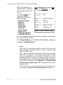
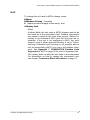
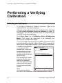
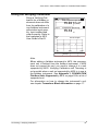
User Guide Fieldbus Option for FOUNDATION Fieldbus User Guide Fieldbus Option for FOUNDATION Fieldbus Dear user, We have made every effort to ensure the accuracy of the contents of this manual. Should any errors be detected, we would greatly appreciate to receive suggestions to improve the quality of the contents of this manual. The above not withstanding, we can assume no responsibility for any errors in this manual or their eventual consequences. We reserve rights to make modifications to this manual without any further notice. For more detailed technical data about MC5 Multifunction Calibrator, please refer to MC5 User Guide or contact the manufacturer. © Copyright 2007 BEAMEX OY AB Ristisuonraitti 10 68600 Pietarsaari FINLAND Tel +358 - 10 - 5505000 Fax +358 - 10 - 5505404 E-mail: [email protected] Internet: http://www.beamex.com 8822500 / UEMC5FF / 002157 Trademarks QCAL® is a registered trademark owned by Oy Beamex Ab. FOUNDATION™ Fieldbus is a registered trademark of the Fieldbus Foundation. PROFIBUS® is a registered trademark of PROFIBUS International. HART® is a registered trademark of the HART Communication Foundation. Other trademarks are property of their respective owners. Contents General ......................................................................................................... 1 What is Fieldbus................................................................................................. 1 Terminology........................................................................................................ 2 Notes and Warnings........................................................................................... 3 MC5, FI5 and FOUNDATION Fieldbus .............................................................. 4 Calibration Procedure of a Fieldbus Instrument, General ............................ 4 Device Descriptions............................................................................................ 6 Viewing Device Descriptions in MC5............................................................ 6 Device Description Sender........................................................................... 7 Fieldbus Instruments and Beamex's Calibration Database Software ................. 8 Connecting to a FOUNDATION Fieldbus Instrument............................... 9 Method 1: Supply from the Calibrator............................................................... 10 Method 2: External Supply ............................................................................... 12 Method 3: Connecting MC5 to a Fieldbus Segment ......................................... 13 Fieldbus and MC5's Basic Mode.............................................................. 14 Connecting to a FOUNDATION Fieldbus Instrument ....................................... 14 Fieldbus Window Setup Menu.......................................................................... 16 Disconnect Device ..................................................................................... 16 Device Information ..................................................................................... 16 Transducer Block Information .................................................................... 17 Mode Block ................................................................................................ 18 Select Output ............................................................................................. 18 Trim Fieldbus Device ................................................................................. 18 Add a Fieldbus Device to Database ........................................................... 19 Unit............................................................................................................. 21 Performing a Verifying Calibration .......................................................... 22 Selecting the Instrument................................................................................... 22 Doing the Verifying Calibration ......................................................................... 23 Calibrating (Trimming, Adjusting) a Fieldbus Instrument.................................. 24 Fieldbus Communication Settings .......................................................... 27 Appendix 1, FOUNDATION Fieldbus Units Supported by MC5 ............ 28 Appendix 2, Useful FOUNDATION Fieldbus Codes ............................... 31 Notes........................................................................................................... 34 User Guide – MC5 Fieldbus Option for FOUNDATION Fieldbus General MC5's FOUNDATION Fieldbus option allows you to calibrate FOUNDATION Fieldbus instruments. All you need is a fieldbus compatible MC5 and a FI5 Fieldbus Interface suited for your fieldbus type. The MC5/FI5 for FOUNDATION Fieldbus features listed below are presented in more detail further on in this manual. • Seen as a guest device in a fieldbus segment already having a Link Active Scheduler (LAS, segment's master device). • Takes care of the Link Active Scheduler (LAS) duties when connecting to a segment without a master device. • Capability to read and edit the instrument Tag. • Read and assign the instrument Node Address. • Read and edit the Transducer Block parameters. • Device Descriptions supported. Note. MC5/FI5 does not support Device Description Methods. What is Fieldbus Fieldbus is an industrial digital communications network specifically designed for process automation use. It is meant to replace the existing standard 4 … 20 mA analog signal. Fieldbus technology has been around since late 80's, but developing an international standard took a long time. There still are several different types of fieldbus implementations, but some of them have become more dominant than others. The two most widely spread types are: • FOUNDATION Fieldbus (www.fieldbus.org/) and • PROFIBUS (www.profibus.com/pb/profibus/process/). Both are based on IEC fieldbus standard, 61158. General 1 User Guide – MC5 Fieldbus Option for FOUNDATION Fieldbus Terminology There are some inconsistencies between the terminologies used when calibrating/adjusting/trimming traditional analog instruments and new fieldbus instruments. For both instrument types, the procedure has three phases: 1. Comparing the instrument against a more accurate device (calibrator). This documents the instrument's state "As Found". If all is well (instrument is accurate enough), the 2nd and 3rd phase are not needed. 2. Adjusting/trimming the instrument. 3. Re-comparing to create an "As Left" document of the instrument's state after adjustment/trimming. The leftmost picture below presents the terms used when calibrating analog instruments. The rightmost one shows the terms used in fieldbus instruments and fieldbus control system software. The numbers of the three phases are shown in the middle. S ta rt S ta rt 1 V E R IF Y IN G C a lib r a tio n A s F C A L IB R A T IO N A s F o u n d n o N e e d o f A d ju s tm e n t? n o y e s E rro r S m a ll E n o u g h ? o f e n t? ra - C A L IB R A T IO N n o y e s C A L IB R A T IO N A s L e ft E n d y e s ) 2 A d ju s tm e n t/ T r im m in g n o N e e d A d ju s tm (C a lib tio n 3 E rro r S m a ll E n o u g h ? y e s V E R IF Y IN G C a lib r a tio n A s L E n d For analog instruments the term "Calibration" is used for comparison phases (1st and 3rd). Phase two is called "Adjustment" or "Trimming". In the user interfaces and manuals of fieldbus instruments and fieldbus control system software, the second phase is called "Calibration", "Adjustment" and/or "Trimming". So, to avoid confusion Beamex uses the term "Verifying Calibration" for the comparison phases in fieldbus environment. 2 General User Guide – MC5 Fieldbus Option for FOUNDATION Fieldbus Notes and Warnings This manual describes the use of MC5 and FI5 for FOUNDATION Fieldbus. For a more general fieldbus information, please refer to your fieldbus control system manuals as well as the manuals for instruments to be calibrated. Terms like Function Block Parameters [AUTO, OOS (Out of Service), MAN], Transducer Block etc. should be familiar before attempting to calibrate any fieldbus instruments. The more instruments a fieldbus segment contains, the slower the communication is. Be patient. WARNINGS! When calibrating an instrument that is part of a control system (live segment), first make sure, the control loop the instrument is part of is set to manual. Also remember to check other dependencies between the instrument to be calibrated and other instruments. Finally, set the Transducer Block of the instrument to be calibrated in Out of Service mode before doing the calibration. Failure to do/check these things may result in unexpected behavior of the control system. The consequences may be serious damage, injuries or death! Using MC5 and FI5 to change the parameters of an instrument may result in discrepancies: A fieldbus host control system may mirror all instrument parameters in its permanent database. In such a case, when returning an instrument with changed parameters to a live segment, ensure that the parameters are also available in the control system's permanent database. Also verify that the new parameters do not result in an unstable control loop. Do not connect two client devices (e.g. MC5/FI5 and a Field Communicator) at the same time to the same fieldbus segment! They may clash and make the fieldbus segment unstable. General 3 User Guide – MC5 Fieldbus Option for FOUNDATION Fieldbus MC5, FI5 and FOUNDATION Fieldbus A FOUNDATION Fieldbus segment always has a master device called Link Active Scheduler (LAS). Beamex's MC5 and FI5 are together seen as a guest device (visitor). Connecting FI5 only to the fieldbus does not "awaken" LAS, but once MC5 is communicating with FI5, the LAS should indicate that a guest device is part of a fieldbus segment. If a fieldbus segment does not have a LAS, MC5/FI5 takes care of the LAS duties. Calibration Procedure of a Fieldbus Instrument, General This chapter presents the broad outline of a calibration procedure when calibrating a FOUNDATION Fieldbus instrument using MC5 and FI5. The focus is on presenting requirements unique for FOUNDATION Fieldbus. Being aware of the details presented here allows you to perform a safe and fluent calibration procedure. A more detailed description of connecting MC5 and FI5 to a FOUNDATION Fieldbus as well as performing the actual calibration is presented further on in this manual. 1. Preparing for the Calibration Procedure There are two ways to calibrate a FOUNDATION Fieldbus instrument that is part of a live fieldbus segment: Doing it on site or taking the instrument to a workshop for calibration. In both cases: • Set the instrument's Transducer Block in Out of Service (OOS) mode (if applicable). This informs the control system that the instrument's input signal is not available (usable). • Make sure any other dependencies are set to manual or other corresponding state. If you calibrate the instrument on site, do the necessary connections and continue to step 2. When taking the instrument to a workshop for calibration, the following additional task is needed: • Set the instrument as a "Spare Device" in the control system ("Off Line" in some systems). 4 General User Guide – MC5 Fieldbus Option for FOUNDATION Fieldbus See chapter Notes and Warnings on page 3 for possible risks when working in a live segment. 2. Verifying Calibration, As Found Perform the Verifying Calibration using MC5/FI5 for FOUNDATION Fieldbus as presented in chapters further on. Verifying Calibration of fieldbus instruments is basically done as the calibration of analog and HART® instruments. The minor differences that exist are due to the instrument's fully digital output. Notes. To be able to perform a Verifying Calibration, the instrument needs to have a Tag and the Node Address can not be in the Default Address area. New FOUNDATION Fieldbus instruments are often shipped with an empty or default Tag and the Node Address is in the Default Address area. Enter a temporary Tag and Node Address to do the Verifying Calibration of a new instrument. 3. Calibration (Trimming, Adjusting) Calibrate (Trim, Adjust) the fieldbus instrument using MC5/FI5 as presented in chapters further on. Note. MC5 and FI5 affect only the instrument's Transducer Block. It is there the instrument's calibration parameters are located. 4. Verifying Calibration, As Left Again, perform the Verifying Calibration using MC5/FI5 as presented in chapters further on. 5. Returning the Instrument to a Live Fieldbus Segment Returning an instrument to a live fieldbus segment requires opposite tasks than those done in step 1. Again, see chapter Notes and Warnings on page 3 for possible problems when returning instruments to a live segment. General 5 User Guide – MC5 Fieldbus Option for FOUNDATION Fieldbus Device Descriptions Each FOUNDATION fieldbus instrument type is unique in what kind of parameters it has in its memory. A few common parameters are similar in all devices, but to fully communicate with a FOUNDATION fieldbus instrument, you need to have a device description file that defines all the parameters in the instrument. Device description files are done by the instrument manufacturers and made available via manufacturer's and certain fieldbus sites. MC5 accesses only the instrument's Transducer Block. Therefore Beamex publishes special device descriptions for MC5 and the instruments connected to it. Please contact Beamex if you need device descriptions for new instruments. For contact info, see the first pages of this manual. The following chapters describe how available device descriptions can be viewed in MC5 and also how to add new device descriptions to MC5. Viewing Device Descriptions in MC5 To view device descriptions saved in MC5's memory, press: D/Menu C/Others and 4/Device Description Information. Each row in the list is a device description. The lower window displays detailed data for the highlighted device and the version number of the Device Description File in MC5. 2 8 .1 2 .2 0 0 6 1 2 :2 8 D E V IC E D E S C R IP T IO N S H o n e y H o n e y H o n e y H o n e y N e le s P R E le P R E le R o s e m R o s e m R o s e m R o s e m M a D e D e D D D D n u v ic v ic R w e ll: w e ll: w e ll: w e ll: J a m e c tro n c tro n o u n t o u n t o u n t o u n t fa c tu r e T y p e R e v e v is io S T A 1 0 0 S T T 1 7 F S T T 3 5 F S T T 4 0 F s b u ry : N ic : P R e t ic : P R e t In c : 6 4 4 In c : 3 0 5 In c : 3 0 5 In c : 3 2 4 e r = e = is io n = - S T R 9 0 0 D 8 0 0 F F o p 5 3 5 0 o p 5 3 5 0 1 1 4 M V 0 0 0 0 0 E 0 5 0 3 2 0 n = 0 3 0 1 F ile V e r s io n 4 .1 C lo s e If the same device name is shown twice in the list, there is some difference in the Device Type, Device Revision and/or DD Revision detail data. 6 General User Guide – MC5 Fieldbus Option for FOUNDATION Fieldbus Device Description Sender Beamex offers a tool for sending device descriptions to MC5. Running the Device Description Sender software opens a window with a list of device description data it contains. Hint. If the highlight is as shown in the picture above, both FOUNDATION Fieldbus and Profibus PA device descriptions are sent to MC5. If you, e.g. have FOUNDATION Fieldbus instruments only, highlight corresponding row and send only FOUNDATION Fieldbus instrument device descriptions to MC5. Click the secondary mouse button to view details of the selected set of device data (the secondary mouse button is the rightmost button, if you use the mouse with your right hand). Details window: Please contact Beamex if you need Device Descriptions for new instruments. For contact info, see the first pages of this manual. General 7 User Guide – MC5 Fieldbus Option for FOUNDATION Fieldbus Fieldbus Instruments and Beamex's Calibration Database Software CMX Calibration Management Software V2, revision 2.1 and later support fieldbus instruments. Older calibration software (QM6, QD3 etc.) do not support fieldbus instruments. 8 General User Guide – MC5 Fieldbus Option for FOUNDATION Fieldbus Connecting to a FOUNDATION Fieldbus Instrument The following subchapters present different connection methods. In the two first methods, the instrument is not part of a live segment. In the third method MC5 and FI5 communicate with an instrument connected to a live factory fieldbus segment. Beamex recommends that instruments should first be removed from a live segment before attempting to communicate with it using MC5 and FI5. For advice on how to remove an instrument from a live segment, see chapter Calibration Procedure of a Fieldbus Instrument, General on page 4. For further information, please refer to your fieldbus control system manuals as well as the instrument's manual. Chapter Notes and Warnings on page 3 contains information of things to be aware of when working with live segments. Notes. There are no polarity requirements when connecting FI5 to a fieldbus segment. FI5 takes the power supply from the fieldbus, not via the FI5/MC5 serial communication cable. The current consumption of FI5 is between 15 to 20 mA. The current consumption of fieldbus instruments are typically between 10 to 20 mA each. Methods 1 and 2 do not require that the connections are done using a fieldbus compliant cable. A pair of standard measurement cables can be used. However, when using longer connecting cables there may be need for fieldbus terminators. Connecting to a FOUNDATION Fieldbus Instrument 9 User Guide – MC5 Fieldbus Option for FOUNDATION Fieldbus Method 1: Supply from the Calibrator In this method, the instrument is not part of the process or a live factory fieldbus segment. The instrument communicates with MC5 as a standalone instrument and MC5 supplies the power for the fieldbus "stub". The following picture presents the connections when you want MC5 to provide the power supply without measuring the current consumption: F ie ld b u s T r a n s m itte r X F F M C 5 C o n n e c tio n F ie ld b u s T e r m in a ls 5 0 o h m T / C C O M P / P R T IN T . R J 2 -w T / C , L o w V 4 -w R , R T D m e a s 1 + 2 4 V V , 1, x m t r m e a s / s in k T / C O R E X T W IR E S O N L Y 3 S E N S O R M E A S U R E & S IM U L A T E & 4 -w V , , H A R T m e a s M O U T P U T E T 6 0 M ® E A S U R E E a x in p u t : V D C / 3 0 V A C L o w V MC5 provides the power supply and receives fieldbus data via FI5 Fieldbus Interface. Depending on the instrument's input signal, it is either generated/simulated or measured with MC5 (not included in the picture). MC5's power supply is always available provided the E module is not assigned for other duties in either Basic Mode window. 10 Connecting to a FOUNDATION Fieldbus Instrument User Guide – MC5 Fieldbus Option for FOUNDATION Fieldbus Notes. Ensure that the loop also includes a resistor with a resistance of approx. 50 ohms between MC5 and the network. See also notes on page 9. To be able to use this method, MC5 needs to be fieldbus compatible, i.e. able to source current both for FI5 and the fieldbus instrument(s). See notes on page 9 for current consumption specifications. Max. load for a fieldbus compatible MC5 is approx. 40 mA. Max. load for a non-fieldbus compatible MC5 is 25 mA. If you have a non-fieldbus compatible MC5, please contact Beamex to have it serviced to be fieldbus compatible. Beamex's contact info is in the beginning of this manual. Meanwhile, use the method presented on next page. If you want to monitor the current consumption of the fieldbus "stub" and FI5, configure one of MC5's windows to source current (Quantity "Current" and Function/Port "E: I(meas)"). Then do the connections as shown in the picture below. F ie ld b u s T r a n s m itte r X F F M C 5 C o n n e c tio n F ie ld b u s T e r m in a ls 5 0 o h m T / C C O M P / P R T 2 -w 2 -w IN T . R J W T / C , L o w V 4 -w R , R T D m e a s m e a s / s in k T / C O R E X T IR E S O N L Y 3 S E N S O R M E A S U R E & S IM U L A T E & 4 -w V , , H A R T m e a s M O U T P U T E T 6 0 Connecting to a FOUNDATION Fieldbus Instrument 1 + 2 4 V V , 1, x m t r x m t r M ® E A S U R E E a x in p u t : V D C / 3 0 V A C L o w V 11 User Guide – MC5 Fieldbus Option for FOUNDATION Fieldbus Method 2: External Supply This is also a method where the instrument is not part of the process or a factory fieldbus segment. The instrument communicates with MC5 as a standalone instrument. A separate power supply provides the loop power for the fieldbus "stub". The following picture presents the connections: F ie ld b u s T r a n s m itte r X F F M C 5 C o n n e c tio n F ie ld b u s T e r m in a ls 5 0 o h m P o w e r S u p p ly T / C C O M P / P R T IN T . R J 2 -w T / C , L o w V 4 -w R , R T D m e a s 1 + 2 4 V V , 1, x m t r m e a s / s in k T / C O R E X T W IR E S O N L Y 3 S E N S O R M E A S U R E & S IM U L A T E & 4 -w V , , H A R T m e a s M O U T P U T E T 6 0 M ® E A S U R E E a x in p u t : V D C / 3 0 V A C L o w V MC5 receives fieldbus data via FI5 Fieldbus Interface. Depending on the instrument's input signal, it is either generated/simulated or measured with MC5 (not included in the picture). Note. When using fieldbus compliant power supplies, no additional resistors are needed. With conventional power supplies, include an approx. 50 ohm resistor between the power supply and the network. 12 Connecting to a FOUNDATION Fieldbus Instrument User Guide – MC5 Fieldbus Option for FOUNDATION Fieldbus Method 3: Connecting MC5 to a Fieldbus Segment In this method MC5 communicates with the instrument via a live factory fieldbus segment possibly containing several instruments. Please read chapter Notes and Warnings on page 3 before attempting to connect using this method. Beamex cannot be held responsible for any damages caused by connecting MC5 to a live factory fieldbus segment. F ie ld b u s T r a n s m itte r X F F M C 5 C o n n e c tio n F ie ld b u s T e r m in a ls F ie ld b u s T / C C O M P / P R T S e g m e n t IN T . R J 2 -w T / C , L o w V 4 -w R , R T D m e a s 1 + 2 4 V V , 1, x m t r m e a s / s in k T / C O R E X T W IR E S O N L Y 3 S E N S O R M E A S U R E & S IM U L A T E & 4 -w V , , H A R T m e a s M O U T P U T E T 6 0 M ® E A S U R E E a x in p u t : V D C / 3 0 V A C L o w V Notes. Connecting to a live factory fieldbus segment does not require any additional resistors. The segment already includes the required impedance that enables digital communication. See notes on page 9 for current consumption specifications. In some cases, the power supply of the fieldbus segment cannot maintain a sufficient voltage level when MC5/FI5 is added to the segment. As a result, the communication between MC5/FI5 and the fieldbus transmitter cannot be initiated. When this happens, use one the previously mentioned methods. Connecting to a FOUNDATION Fieldbus Instrument 13 User Guide – MC5 Fieldbus Option for FOUNDATION Fieldbus Fieldbus and MC5's Basic Mode Connecting to a FOUNDATION Fieldbus Instrument To initiate communication with a fieldbus instrument, press: D/Menu, B/Window 2 Setup, if needed and 5/HART / Fieldbus. Select Foundation H1 from the pop-up list. 2 2 .1 2 .2 0 0 6 1 1 2 :4 6 R T D -te m p e ra tu re E T : R T D T e m p . S im 1 0 .0 0 Q u a n [C u rr g a u g Fk P u na c [E :I(M tity e n t] e tio n /P o r t e a s )] D is p la y M o d e [E n g . U n its ] 2 C u rre EH : A C R u T r r e n F O U N D A P R O F IB U W in d o w S e tu p 1 n t t M e a s u re m e n t 3 .9 8 5 5 T IO N H 1 S P A W in d o w S e tu p 2 U n it [m A ] H A R T / F ie ld b u s m A O th e rs C lo s e M E N U Notes. The HART / Fieldbus menu options are disabled if the other window already has one of the available Fieldbus communications active. Change the setup of the other window to enable the HART / Fieldbus menu option. 14 Fieldbus and MC5's Basic Mode User Guide – MC5 Fieldbus Option for FOUNDATION Fieldbus Refer to chapter Connecting to a FOUNDATION Fieldbus Instrument on page 9 for information on how to connect MC5 and a fieldbus instrument. 2 2 .1 2 .2 0 0 6 1 2 :5 2 F O U N D A T IO N H 1 F F - 1 .0 2 .0 .0 0 .re l D e v ic e s fo u n d ( N o d e A d d r : T a g ) : 0 2 4 : T T 1 2 2 -A P MC5 searches for fieldbus devices connected to FI5 and opens a window similar to the one seen to the right. Up to 32 instruments may be found in the same fieldbus segment. B a c k R e s ta rt E d it S e le c t Use the C/Edit button to edit the selected instrument's Tag and/or its Node Address. Choose an instrument by pressing D/Select (optionally either the or the key). Note. If MC5 does not have required Device Descriptions, full communication cannot be initiated. In this case a window opens telling what kind of Device Description is needed. Contact Beamex to receive instructions on how to correct the problem. After required instrument data is read, MC5 returns to Basic Mode with the fieldbus instrument assigned to the chosen window. The measurement quantity of the window where the fieldbus instrument was selected to is automatically changed to the quantity of the fieldbus instrument's primary value. The standard Window Setup menu is replaced by a fieldbus menu (see adjacent picture). Fieldbus and MC5's Basic Mode 0 2 .0 4 .2 0 0 7 1 1 3 :4 2 R T D -te m p e ra tu re E T : R T D T e m p . S im . 1 0 .0 0 D is c o n n e c t D e v ic e g a u g e kD P e a v i c e In fo r m a tio n T ra n s d u c e r B lo c k In fo r m a tio n 2 T e m p e ra tu re F I5 -F F /P V :T T 1 2 2 -A P M o d e B lo c k [O O S ] S e le c t O u tp u t [P V ] k P a T r im F ie ld b u s S ta tu s : G o o d ( N o n - c a s c a d eD ) e v ic e 1 0 .0 4 A d d F ie ld b u s D e v ic e to D a ta b a s e K W a i ln i b d r o o w i n 1t i S t e i lt a u p W V i n a d l i ot s w e 2 kS e e n t ut t p ä O th e rs C lo s e V a lik k o M E N U 15 User Guide – MC5 Fieldbus Option for FOUNDATION Fieldbus Fieldbus Window Setup Menu A window reserved for fieldbus communication has its own menu. All menu items are presented in the following subchapters. Disconnect Device This option disconnects the fieldbus instrument from MC5/FI5. To disconnect, select D/Menu and B/Window 2 Setup, if needed 1/Disconnect Device. The fieldbus communication is terminated and the fieldbus menu is replaced by the standard Window Setup menu. Device Information To open the Device Information window, press D/Menu and B/Window 2 Setup, if needed 2/Device Information. This window contains read-only information of the connected instrument. Note that the Tag and Node Address fields cannot be edited here. It is done while connecting to the instrument using the C/Edit Function Key. 16 1 4 .0 9 .2 0 0 6 1 3 :0 1 D E V IC E IN F O R M A T IO N T a g T T 1 2 2 -A P D e v ic e ID 3 2 _ _ 6 5 8 3 7 2 8 7 7 3 8 3 7 2 6 6 7 9 7 8 6 9 N o d M a n D e v D e v D D F in a 2 4 e A d d re s s u fa c tu re r ic e T y p e ic e R e v is io n R e v is io n l A s s e m b ly In fo W A E le c tr o n ic s M S A T 1 0 4 1 1 0 C lo s e Fieldbus and MC5's Basic Mode User Guide – MC5 Fieldbus Option for FOUNDATION Fieldbus Transducer Block Information To open the Transducer Block Information window, press D/Menu and B/Window 2 Setup, if needed 3/Transducer Block Information. The contents of this window depend on the connected instrument. This is because Transducer Block parameters vary from instrument to instrument. 1 4 .0 9 .2 0 0 6 1 3 :2 2 T R A N S D U C E R S T _ R E V T A G _ D E S T R A T E A L E R T _ M O D E _ B B L O C K _ T R A N S D X D _ E R R P R IM A R S E N S O R L IN _ T Y P B L O C K S C G Y K E Y L K E R R U C E R _ T Y P E O R Y _ V A L U E _ U N IT _ M E A S _ T Y P E E ° C C lo s e E d it Normally you do not need to edit any of the parameters shown here. The most likely one in need of editing is the unit. If MC5 supports the unit, it is shown as in the example picture above. If MC5 does not support the unit, a numeric value is shown instead of the unit. Notes. To quickly browse through the list of parameters use MC5's and keys. When editing a unit field, MC5 displays the numeric code for the unit (the code is as defined in fieldbus specifications). Please refer to Appendix 1 on page 28 or the instrument's manual to see which numeric code corresponds to which unit. Several other Transducer Block parameters are also edited using a numeric code. Fieldbus and MC5's Basic Mode 17 User Guide – MC5 Fieldbus Option for FOUNDATION Fieldbus Mode Block Mode Block is an important Transducer Block parameter while calibrating instruments. That's why it is directly available via MC5's menu. Use this to set the instrument in either OOS - Out Of Service or Auto - Automatic mode. See also chapter Notes and Warnings on page 3 Select Output Select Output is another important Transducer Block parameter directly available via MC5's menu. The available options vary depending on the instrument at hand. Some instruments require that another output is selected when trimming/adjusting the instrument. That is why the selection of output is made easily available. Trim Fieldbus Device This option allows you to trim/adjust a fieldbus instrument without performing a Verifying Calibration. When selected, you first need to enter instrument data as presented in MC5 User Guide's Section D (Chapter Maintaining MC5's Instrument database). The rest of the trimming/adjustment procedure is done as presented in chapter Calibrating (Trimming, Adjusting) a Fieldbus Instrument on page 24 of this manual. 18 Fieldbus and MC5's Basic Mode User Guide – MC5 Fieldbus Option for FOUNDATION Fieldbus Add a Fieldbus Device to Database This is a semi-automatic tool for adding a fieldbus instrument to MC5's instrument database. To start adding, press 0 2 .0 4 .2 0 0 7 1 1 3 :5 5 R T D -te m p e ra tu re E T : R T D T e m p . S im . 1 0 .0 0 The instrument is added and MC5 places some default values for calibration related fields that are missing in the instrument's memory. D e v ic e In fo r m a tio n T ra n s d u c e r B lo c k In fo r m a tio n D/Menu and B/Window 2 Setup, if needed 7/Add Fieldbus Device to Database. D is c o n n e c t D e v ic e 2 T e m p e ra tu re F I5 -F F /P V :T T 1 2 2 -A P 1 0 .0 4 M o d e B lo c k [O O S ] S e le c t O u tp u t [P V ] T r im F ie ld b u s D e v ic e A d d F ie ld b u s D e v ic e to D a ta b a s e K W a i ln i b d r o o w i n 1t i S t e i lt a u p W V i n a d l i ot s w e 2 kS e e n t ut t p ä O th e rs C lo s e V a lik k o M E N U Note. MC5 supports Tags and Device IDs that have max. 25 characters. Longer Tags and Device IDs are truncated. The following table presents which parameter in a fieldbus instrument gets linked to which field in MC5 when adding a fieldbus instrument to MC5: Fieldbus Instrument Parameters Corresponding Fields in MC5 PD_TAG Position ID DEVICE_ID Device ID FINAL_ASSY_NUM Serial Number Fieldbus and MC5's Basic Mode 19 User Guide – MC5 Fieldbus Option for FOUNDATION Fieldbus When the instrument is added to MC5, a display like the adjacent picture opens. To edit the default values, press B/Edit. Edit/check at least the following fields: - Error Calculation Method - Reject if > - Input Port - Input Range - Input Unit - Output Range - Output Unit - Calibration Method - Calibration Points 1 5 .0 9 .2 0 0 6 0 8 :4 2 IN S T R U M E N T 1T 1 T 2 1 - 2 T 2 T - -A 0 P 0 3 . 1 T r a n s fe r F u n c tio n L in e a r C a l. P o in ts 5 ¯ IN P U T U n it M e th o d S e n s o r T y p e 0 .0 0 0 0 0 0 ... 1 0 0 .0 0 0 °C S im u la te d P t1 0 0 a 3 8 5 O U T P U T U n it M e th o d 0 .0 0 0 0 0 0 ... 1 0 0 .0 0 0 °C F O U N D A T IO N H 1 B a c k E d it C a lib r a te M E N U For more information MC5's instrument database, see section D in your MC5 User Guide. The Output Method for a FOUNDATION Fieldbus instrument is always "FOUNDATION H1". Notes. MC5 sets its own internal default values to the input and output ranges. Check/edit them in order to create valid Verifying Calibrations. When adding a fieldbus instrument to MC5, the measurement unit is fetched from the fieldbus instrument. If MC5 does not support the unit, you need to change it to a unit supported by MC5. Verifying Calibration and Trimming is not possible when a unit not supported by MC5 is in use in the fieldbus instrument. See Appendix 1, FOUNDATION Fieldbus Units Supported by MC5 on page 28 for a list of supported unit. For information on how to change the instrument's unit, see chapter Transducer Block Information on page 17. 20 Fieldbus and MC5's Basic Mode User Guide – MC5 Fieldbus Option for FOUNDATION Fieldbus Unit To change the unit used in MC5's display, press D/Menu, B/Window 2 Setup, if needed 8 (opens the second page of the menu) and 4/Display Unit. Notes. In Basic Mode, the unit used in MC5's display need not be the same as in the instrument itself. Fieldbus instruments use numeric codes for the units they support. When connecting to an instrument, MC5 gets the unit from the instrument. If the unit is not supported in MC5, the unit's numeric code is shown and the Quantity is set to "None". Verifying Calibration and Trimming is not possible when a unit not supported by MC5 is in use in the fieldbus instrument. See Appendix 1, FOUNDATION Fieldbus Units Supported by MC5 on page 28 for a list of supported unit. This setting does not alter the unit used in the instrument. For information on how to change the instrument's unit, see chapter Transducer Block Information on page 17. Fieldbus and MC5's Basic Mode 21 User Guide – MC5 Fieldbus Option for FOUNDATION Fieldbus Performing a Verifying Calibration Selecting the Instrument To be able to calibrate a fieldbus instrument, it has to be added to MC5's instrument database. Adding the instruments can be done using the utility described in chapter Add a Fieldbus Device to Database on page 19. Additionally, you can also manually enter the instrument data into MC5's instrument database. From Basic Mode, go to Calibration Mode (A/Calibration Mode). Then select the instrument to be calibrated from MC5's list of available instruments. If you are already connected to the fieldbus instrument (fieldbus communication started in Basic Mode), MC5 continues directly from the Instrument Window to the Calibration Windows. If fieldbus communication is not started, MC5 prompts you to start the communication and select the instrument in a window similar to the adjacent picture. 2 2 .1 2 .2 0 0 6 1 2 :5 2 F O U N D A T IO N H 1 F F - 1 .0 2 .0 .0 0 .re l D e v ic e s fo u n d ( N o d e A d d r : T a g ) : 0 2 4 : T T 1 2 2 -A P MC5 accepts the fieldbus instrument as the instrument to be calibrated only if its instrument data matches with the data of the instrument selected in MC5. Note. B a c k R e s ta rt E d it S e le c t The instrument data in MC5 and in the instrument to be connected need to match. 22 Performing a Verifying Calibration User Guide – MC5 Fieldbus Option for FOUNDATION Fieldbus Doing the Verifying Calibration Doing a Verifying Calibration for a fieldbus instrument does not differ from the calibration of a non-fieldbus instrument with similar input quantity, input method and output quantity. Refer to the examples in MC5 User Guide's Part D. In p u t 2 2 .1 2 .2 0 0 6 1 3 :3 0 R T D T e m p e r a tu r e [E T :S im u l] P t1 0 0 a 3 8 5 ° C (IT S 9 0 ) 7 5 .0 0 O u tp u t T e m p e r a tu r e [F I5 -F F /P V ] 7 5 .1 6 °C S ta tu s : G o o d (N o n -c a s c a d e ) E rro r 1 .0 0 0 .1 6 % + o f s p a n 0 - 0 % P a u s e 5 0 % 1 0 0 % F o rc e A c c e p t Note. When adding a fieldbus instrument to MC5, the measurement unit is fetched from the fieldbus instrument. If MC5 does not support the unit, you need to change it to a unit supported by MC5. Verifying Calibration and Trimming is not possible when a unit not supported by MC5 is in use in the fieldbus instrument. See Appendix 1, FOUNDATION Fieldbus Units Supported by MC5 on page 28 for a list of supported unit. For information on how to change the instrument's unit, see chapter Transducer Block Information on page 17. Performing a Verifying Calibration 23 User Guide – MC5 Fieldbus Option for FOUNDATION Fieldbus Calibrating (Trimming, Adjusting) a Fieldbus Instrument To start Calibrating (Trimming, Adjusting) a Fieldbus Instrument in Calibration Mode, press D/Menu and 1/Start Fieldbus Adjustment while viewing the calibration windows. The opened menu has two pages as shown in the adjacent picture. In p u t 2 2 .1 2 .2 0 0 6 1 3 :3 0 R T D T e m p e r a t u Tr e r i [m E T L : o S w i m e ru l ] P 0 t % 1 0 R0 a a n 3 g 8 e 5 2 2 .° 1 C 2 . ( 2 I 0 T 0 S 6 9 0 1 ) 3 : 3 0 In p u t T r i m R T U D p Tp e mr p e r a t u Dr e e [v E i c T e : S i m 1 0 0 % R a n g e P I n t 1 f o0 0 r m a a 3 t 8i o 5 O u tp u t T e m p e r a tu r e [F I5 -F F /P V ] ° C (IT S 9 0 ) T ra n s d u c e C h e c k A n y B lo c k ° VC a l u e O u tp u t T e m p e r a t u r e [ F I I 5 n - f F o F r m/ P a V t ] i o O O S - O u t O f S e r v ic e M o d e B lo c k AE r u r o t o r - A u t o m a t i c [O O S ] °C 1 .0 0 0 .1 2 % o f s p a n + S e le c t O u tp u t [P V ] E rro r 1 .0 0 0 .1 6 % o f s p a n + T r im M e th o d 0 [F a c to r y tr im ] 0 .0 0 0 .1 2 u l] 7 5 .0 0 n r n 7 5 .1 6 - 0 0 % P a u s e 5 0 % F o rc e A c c e p t - E n d F ie ld b u s A d j u s t m e n1 0 t 0 % 0 % P a u s e 5 0 % 1 0 0 % F o rc e A c c e p t The actual Calibrating (Trimming, Adjusting) procedure varies depending on the instrument at hand. Please refer to your fieldbus instrument's manual for device specific information. The following list present the most common steps together with some hints on what to additional steps may be included: 1. Certain fieldbus instruments require that the mode of the Transducer Block is set to Out of Service Mode before any Calibration (Trimming, Adjustment) is allowed. Use the Fieldbus Instrument Adjustment menu's 4/Mode Block option to set the mode. Also check the note at the end of this chapter. 24 Performing a Verifying Calibration User Guide – MC5 Fieldbus Option for FOUNDATION Fieldbus 2. If some of the options in the Fieldbus Instrument Adjustment menu's items are greyed (refer to the picture on the previous page), the selected output for that particular instrument cannot be trimmed. Change the output using menu option 5/Select Output. 3. When enabled, check the Trim Method option in the Fieldbus Instrument Adjustment menu. It should be as stated in the instrument's manual (Transducer Block parameter SENSOR_CAL_METHOD). 4. Some instruments have extra parameters that need to be set before Trimming can be performed, e.g CAL_UNIT and TRIM_MODE. For these parameters, use the Transducer Block Information option on the second page of the Fieldbus Instrument Adjustment menu to see/edit all Transducer Block parameters. When the menu is opened, press 8 to see the second menu. Then select 2/Transducer Block Information. 5. To perform the actual trimming procedure, do as follows: Select the 1/Trim Lower 0% Range option from the Fieldbus Instrument Adjustment menu. ● If the input signal is generated/simulated with MC5, the input signal is automatically set to span zero value. ● For instruments where MC5 measures the input and another device generates/simulates the instrument's input, set the input to span zero value. In both cases, MC5's Input window displays the instrument’s input signal. The Output window displays the digital output of the instrument. 6. The lower part of the Output window includes an additional trim field. Use either the C/Fetch Function Key to copy the value shown in the input window or manually enter a value the digital output should be trimmed to. Then use the D/Send Function Key to trim the zero point. The corrected value is sent to Transducer Block parameter, CAL_POINT_LO (or similar, depending on the instrument at hand). Performing a Verifying Calibration 25 User Guide – MC5 Fieldbus Option for FOUNDATION Fieldbus 7. Then select the 2/Trim Upper 100% Range option from the Fieldbus Instrument Adjustment menu. Otherwise, the trimming procedure is similar to phases 5 and 6. In this case, the corrected value is sent to Transducer Block parameter, CAL_POINT_HI (or similar, depending on the instrument at hand). Note. You may also check the trim of any point by using the menu's 3/Check Any Value option. 8. Setting the calibration date in the fieldbus is done by editing the following (or corresponding) Transducer Block parameters: SENSOR_CAL_DATA SENSOR_CAL_WHO SENSOR_CAL_LOC To edit these parameters, use the Transducer Block Information option on the second page of the Fieldbus Instrument Adjustment menu to see/edit all Transducer Block parameters. When the menu is opened, press 8 to see the second menu. Then select 2/Transducer Block Information. 9. To end the trimming procedure, reset all the fields that were modified while enabling Calibration (Trimming, Adjusting), e.g. 4/Mode Block, 6/Trim Method etc. Notes. If the Instrument's Resource Block's mode is set to Out of Service (OOS), the mode of the Transducer Block cannot be changed until the mode of the Resource Block is set to "Auto". The PV output value of some FOUNDATION Fieldbus instruments "freeze" when the mode of the Transducer Block is set to Out of Service (OOS). The instrument's input signal is however still received and you may trim the instrument anyhow. When the Transducer block is set to "Auto" again, the new trim values are automatically taken into use and the output is "alive" again. 26 Performing a Verifying Calibration User Guide – MC5 Fieldbus Option for FOUNDATION Fieldbus Fieldbus Communication Settings You may view/edit fieldbus settings in Basic Mode by pressing: D/Menu, C/Others, 3/Fieldbus Communication Settings. Select 0 2 .0 4 .2 0 0 7 1 1 3 :2 0 R T D -te m p e ra tu re E T : R T D T e m p . S im S e ttin g s 1 0 .0 g a u g e Mk P a a i n t e n a n c e EH : A C R u T r r e n t M e a s u r e m e n t F ie ld b u s C o m m u n ic a tio n s e ttin g s D e v ic e D e s c r ip tio n In fo r m a tio n 3 .9 8 5 5 F O U N D A T IO N H 1 P R O F IB U S P A 2 T e m p e ra tu re F I5 -F F /P V :T T 1 2 2 -A P D a ta L o g g in g m A T r a n s m itte r / S w itc h S im u la tio n 1 0 .0 4 Foundation H1 from the pop-up list. A window opens where the communication settings are presented (see picture below). Normally you do not need to chance the default settings (seen in the adjacent picture). Consult your fieldbus instruments' manual when you plan to change the communication settings. Otherwise you may lose connection with it. W in d o w S e tu p W in d o w S e tu p 1 8 .0 9 .2 0 0 6 2 C lo s e M E N U O th e rs 1 0 :3 0 N E T W O R K P A R A M E T E R S S lo t T im e P h l O v e rh e a d M a x R e p ly D e la F ir s t U n p o lle d N T h is L in k N u m U n p o lle d N M in In te r P d u D P h l P r e a m b le E P h l G a p E x te n s M a x In te r C h a n T im e S y n c C la s C lo s e Fieldbus Communication Settings 1 8 6 y 1 0 o d e 2 4 8 o d e e la y x te n s io n io n S ig n a l S k e w s F a c to ry S e ttin g s 0 0 1 6 0 0 0 3 E d it 27 User Guide – MC5 Fieldbus Option for FOUNDATION Fieldbus Appendix 1, FOUNDATION Fieldbus Units Supported by MC5 Note. Certain instruments may not support all codes listed here. When in doubt, please consult the instrument's manual. Temperature Units Unit Code in Fieldbus Instruments 1000 1001 1002 1003 Displayed Unit in Fieldbus Instruments K °C °F °R Displayed Unit in MC5 K °C °F °R Displayed Unit in Fieldbus Instruments Hz kHz cpm Displayed Unit in MC5 Hz kHz cpm Displayed Unit in Fieldbus Instruments Pa MPa kPa hPa bar mbar torr atm psi psia Displayed Unit in MC5 Pa MPa kPa hPa bar mbar torr atm psi psia Frequency Units Unit Code in Fieldbus Instruments 1077 1081 1083 Pressure Units Unit Code in Fieldbus Instruments 1130 1132 1133 1136 1137 1138 1139 1140 1141 1142 Cont… 28 Appendix 1, FOUNDATION Fieldbus Units Supported by MC5 User Guide – MC5 Fieldbus Option for FOUNDATION Fieldbus Pressure units, continued Unit Code in Fieldbus Instruments 1143 1144 1145 1146 1147 1148 1149 1150 1151 1152 1153 1154 1155 1156 1157 1158 1541 1542 1545 1546 1547 1548 1553 1554 1555 1556 1557 1558 1559 1560 1561 1562 1563 1564 1565 1566 1567 1568 1569 1570 1571 1572 1573 1574 1575 1576 Displayed Unit in Fieldbus Instruments psig 2 gf/cm 2 kgf/cm inH2O inH2O(4°C) inH2O(68°F) mmH2O mmH2O(4°C) mmH2O(68°F) ftH2O ftH2O(4°C) ftH2O(68°F) inHg inHg(4°C) mmHg mmHg(4°C) Paa Pag mPaa mPag kPaa kPag hPaa hPag 2 gf/cm a 2 gf/cm g 2 kgf/cm a 2 kgf/cm g inH2Oa inH2Og inH2Oa(4°C) inH2Og(4°C) inH2Oa(68°F) inH2Og(68°F) mmH2Oa mmH2Og mmH2Oa(4°C) mmH2Og(4°C) mmH2Oa(68°F) mmH2Og(68°F) ftH2Oa ftH2Og ftH2Oa(4°C) ftH2Og(4°C) ftH2Oa(68°F) ftH2Og(68°F) Displayed Unit in MC5 psig 2 gf/cm 2 kgf/cm inH2O inH2O @ 4°C inH2O @ 68°F mmH2O mmH2O @ 4°C mmH2O @ 68°F ftH2O ftH2O @ 4°C ftH2O @ 68°F inHg inHg @ 4°C mmHg mmHg @ 4°C Pa Pa mPa mPa kPa kPa hPa hPa 2 gf/cm 2 gf/cm 2 kgf/cm 2 kgf/cm inH2O inH2O inH2O @ 4°C inH2O @ 4°C inH2O @ 68°F inH2O @ 68°F mmH2O mmH2O mmH2O @ 4°C mmH2O @ 4°C mmH2O @ 68°F mmH2O @ 68°F ftH2O ftH2O ftH2O @ 4°C ftH2O @ 4°C ftH2O @ 68°F ftH2O @ 68°F Cont… Appendix 1, FOUNDATION Fieldbus Units Supported by MC5 29 User Guide – MC5 Fieldbus Option for FOUNDATION Fieldbus Pressure units, continued Unit Code in Fieldbus Instruments 1577 1578 1579 1580 1581 1582 1583 1584 1590 1591 Displayed Unit in Fieldbus Instruments inHga inHgg inHga(0°C) inHgg(0°C) mmHga mmHgg mmHga(0°C) mmHgg(0°C) barg mbarg Displayed Unit in MC5 inHg inHg inHg @ 0°C inHg @ 0°C mmHg mmHg mmHg @ 0°C mmHg @ 0°C bar mbar Displayed Unit in Fieldbus Instruments mA μA V mV μV ohm kohm Displayed Unit in MC5 mA μA V mV μV Ω kΩ Electrical Units Unit Code in Fieldbus Instruments 1211 1212 1240 1243 1244 1281 1284 30 Appendix 1, FOUNDATION Fieldbus Units Supported by MC5 User Guide – MC5 Fieldbus Option for FOUNDATION Fieldbus Appendix 2, Useful FOUNDATION Fieldbus Codes Sensor Types (Variable SENSOR_TYPE) Sensor Type, Code 100 101 102 103 104 105 106 107 108 109 110 111 112 113 114 115 116 117 118 119 120 121 122 123 124 125 126 127 128 129 130 131 132 133 Description Flow sensor unknown Coriolis (Gyroscopic) Electromagnetic mV Ω ΔΩ Nuclear magnetic resonance Positive displacement Refraction Taggin Ultrasonic (Doppler) Ultrasonic (time of travel) Vortex Target Variable area Level sensor unknown Radar Capacitance Nuclear Ultrasonic Float gauge Pressure sensor unknown Resonant wire Vibrating beam Strain gauge Piezo resistive Silicon resonant Temperature sensor unknown PT100_A_385 (IEC 751) PT100_A_392 (JIS 1604) PT200_A_385 (IEC 751) PT500_A_385 (IEC 751) NI120, Edison # 7 CU10, Edison # 15 Cont… Appendix 2, Useful FOUNDATION Fieldbus Codes 31 User Guide – MC5 Fieldbus Option for FOUNDATION Fieldbus Sensor Types, continued Sensor Type, Code 134 135 136 137 138 139 140 141 142 143 144 145 146 147 148 149 150 151 152 153 154 155 156 157 158 159 65520- 65534 65535 Description T/C Type B (IEC 584-1, and NIST 175) T/C Type C (NIST 175) T/C Type E (IEC 584-1, and NIST 175) T/C Type J (IEC 584-1, and NIST 175) T/C Type K (IEC 584-1, and NIST 175) T/C Type N (IEC 584-1, and NIST 175) T/C Type R (IEC 584-1, and NIST 175) T/C Type S (IEC 584-1, and NIST 175) T/C Type T (IEC 584-1, and NIST 175) T/C Type DIN L (DIN 43710) T/C Type DIN U (DIN 43710) BALCO, 3KOhm Contacting Conductivity Toroid Conductivity PT1000_A_385 (IEC 751) Magnetostrictive TDR Level pH ORP Standard Oxygen Amperometric Trace Oxygen Amperometric Steam Sterilizable Oxygen Amperometric Type 1 Steam Sterilizable Oxygen Amperometric Type 2 Free Chlorine Amperometric Total Chlorine Amperometric Monochloramine Amperometric Reserved (Manufacturer Specific) Non-standard Linearity Types (Variable LIN_TYPE) Linearization Type, Code 0 1 2 3 4 5 255 32 Description undefined linear with input linear with output square root square root to the third power square root to the fifth power other Appendix 2, Useful FOUNDATION Fieldbus Codes User Guide – MC5 Fieldbus Option for FOUNDATION Fieldbus Calibration Methods (Variable SENSOR_CAL_METHOD) Calibration Method, Code 100 101 102 103 104 105 106 240-254 255 Description volumetric static weigh dynamic weigh factory trim standard calibration user trim standard calibration factory trim special calibration user trim special calibration Reserved (Manufacturer Specific) other Appendix 2, Useful FOUNDATION Fieldbus Codes 33 User Guide – MC5 Fieldbus Option for FOUNDATION Fieldbus Notes 34 Notes User Guide – MC5 Fieldbus Option for FOUNDATION Fieldbus Notes 35 © Copyright 2007 BEAMEX OY AB Ristisuonraitti 10 FIN-68600 PIETARSAARI FINLAND Phone +358 - 10 - 5505000 Fax +358 - 10 - 5505404 E-mail [email protected] [email protected] Internet http://www.beamex.com Beamex Inc 2270 Northwest Parkway Suite 165 Marietta, GA 30067 U.S.A. Phone 800 888-9892, +1-770-951-1927 Fax +1-770-951-1928 E-mail [email protected] Beamex Limited Newtown Grange Farm Business Park Desford Road NEWTOWN UNTHANK Leicestershire LE9 9FL United Kingdom Phone 01455 821 920 Fax 01455 821 923 E-mail [email protected] Representative: