1
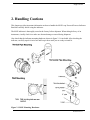
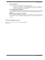
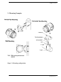
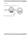
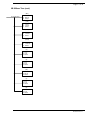
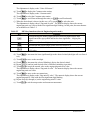
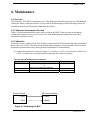
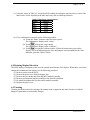
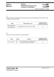
User’s
Manual
Model MLX
Loop Powered Process Indicator
IM 60A02S01-01E-A
IM 60A02S01-01E-A
2nd Edition
Page 2 of 28
Contents
Loop Powered Process Indicator ............................................................................................ 1 Contents .......................................................................................................................................................... 2 1. Introduction ............................................................................................................................................... 3 ■ Regarding This Manual ........................................................................................................ 3 1.1 Safe Use of This Product ........................................................................................................ 4 1.2 Warranty............................................................................................................................... 5 2. Handling Cautions ..................................................................................................................................... 6 2.1 Model and Specifications Check ............................................................................................. 7 2.2 Unpacking ............................................................................................................................. 7 2.3 Storage .................................................................................................................................. 7 2.4 Selecting the Installation Location .......................................................................................... 7 2.5 Insulation Resistance and Dielectric Strength Test.................................................................. 8 2.6 Installation of an Explosion-Protected Instrument .................................................................. 9 2.6.1 Factory Mutual (FM) Certification .................................................................................. 9 2.7 EMC Conformity Standards............................................................................................. 10 3. Installation .............................................................................................................................................. 11 3.1 Mounting Examples ............................................................................................................. 12 4. Wiring ....................................................................................................................................................... 13 4.1 Wiring Precautions .............................................................................................................. 13 4.2 Selecting the Wiring Materials ............................................................................................. 13 4.3 Wiring ................................................................................................................................. 13 4.3.1 Loop Configuration ....................................................................................................... 13 5. Operation ..................................................................................................Error! Bookmark not defined. 5.1 Overview ................................................................................Error! Bookmark not defined. 6. Maintenance ............................................................................................................................................. 22 6.1 Overview ............................................................................................................................. 22 6.2 Calibration Instruments Selection ........................................................................................ 22 6.3 Calibration .......................................................................................................................... 22 6.4 Rotating Display Direction ................................................................................................... 23 6.5 Cleaning .............................................................................................................................. 23 7. General Specifications ............................................................................................................................. 24 7.1 Standard Specifications........................................................................................................ 24 7.2 Model and Suffix Codes ....................................................................................................... 25 7.5 Dimensions .......................................................................................................................... 27 Revision Record ........................................................................................................................................... 28 IM 60A02S01-01E-A
Page 3 of 28
1. Introduction
Thank you for purchasing the Model MLX Loop Powered Process Indicator. Your Model MLX Process
Indicator was precisely calibrated at the factory before shipment. To ensure both safety and efficiency,
please read this manual carefully before you operate the instrument.
The Model MLX field mounted indicator receives DC current signals from electronic transmitters and
indicates process measurement values. This instruction manual gives instructions on handling, mounting,
and wiring of the indicator.
■ Regarding This Manual
• This manual should be provided to the end user.
• The contents of this manual are subject to change without prior notice.
• All rights reserved. No part of this manual may be reproduced in any form without Yokogawa’s
written permission.
• Yokogawa makes no warranty of any kind with regard to this manual, including, but not limited to,
implied warranty of merchantability and fitness for a particular purpose.
• If any question arises or errors are found, or if any information is missing from this manual, please
inform the nearest Yokogawa sales office.
• The specifications covered by this manual are limited to those for the standard type under the
specified model number break-down and do not cover custom-made instruments.
• Please note that changes in the specifications, construction, or component parts of the instrument
may not immediately be reflected in this manual at the time of change, provided that postponement
of revisions will not cause difficulty to the user from a functional or performance standpoint.
• Yokogawa assumes no responsibilities for this product except as stated in the warranty.
• If the customer or any third party is harmed by the use of this product, Yokogawa assumes no
responsibility for any such harm owing to any defects in the product which were not predictable, or
for any indirect damages.
• The following safety symbols are used in this manual:
WARNING
Indicates a potentially hazardous situation which, if not avoided, could result in death or serious injury.
IM 60A02S01-01E-A
Page 4 of 28
CAUTION
Indicates a potentially hazardous situation which, if not avoided, may result in minor or moderate injury. It
may also be used to alert against unsafe practices.
IMPORTANT
Indicates that operating the hardware or software in this manner may damage it or lead to system failure.
NOTE
Draws attention to information essential for understanding the operation and features.
1.1 Safe Use of This Product
For the safety of the operator and to protect the instrument and the system, please be sure to follow this
manual’s safety instructions when handling this instrument. If these instructions are not heeded, the
protection provided by this instrument may be impaired. In this case, Yokogawa cannot guarantee that the
instrument can be safely operated. Please pay special attention to the following points:
(a) Installation
• This instrument may only be installed by an engineer or technician who has an expert knowledge of
this device. Operators are not allowed to carry out installation unless they meet this condition.
• All installation shall comply with local installation requirements and the local electrical code.
(b) Wiring
• The instrument must be installed by an engineer or technician who has an expert knowledge of this
instrument. Operators are not permitted to carry out wiring unless they meet this condition.
• Before connecting the power cables, please confirm that there is no current flowing through the
cables and that the power supply to the instrument is switched off.
(c) Operation
• Do not open the covers when an explosive atmosphere is present.
(d) Maintenance
• Please carry out only the maintenance procedures described in this manual. If you require further
assistance, please contact the nearest Yokogawa office.
• Care should be taken to prevent the build up of dust or other materials on the display glass and the
name plate.
(e) Modification
IM 60A02S01-01E-A
Page 5 of 28
•
Yokogawa will not be liable for malfunctions or damage resulting from any modification made to
this instrument by the customer.
1.2 Warranty
•
•
•
•
•
The warranty shall cover the period noted on the quotation presented to the purchaser at the time of
purchase. Problems occurring during the warranty period shall basically be repaired free of charge.
If any problems are experienced with this instrument, the customer should contact the Yokogawa
representative from which this instrument was purchased or the nearest Yokogawa office.
If a problem arises with this instrument, please inform us of the nature of the problem and the
circumstances under which it developed, including the model specification and serial number. Any
diagrams, data and other information you can include in your communication will also be helpful.
The party responsible for the cost of fixing the problem shall be determined by Yokogawa
following an investigation conducted by Yokogawa.
The purchaser shall bear the responsibility for repair costs, even during the warranty period, if the
malfunction is due to:
− Improper and/or inadequate maintenance by the purchaser.
− Malfunction or damage due to a failure to handle, use, or store the instrument in accordance
with the design specifications.
− Use of the product in question in a location not conforming to the standards specified by
Yokogawa, or due to improper maintenance of the installation location.
− Failure or damage due to modification or repair by any party except Yokogawa or an approved
representative of Yokogawa.
− Malfunction or damage from improper relocation of the product in question after delivery.
− Reason of force majeure such as fires, earthquakes, storms/floods, thunder/lightening, or other
natural disasters, or disturbances, riots, warfare, or radioactive contamination.
IM 60A02S01-01E-A
Page 6 of 28
2. Handling Cautions
This chapter provides important information on how to handle the MLX Loop Powered Process Indicator.
Read this carefully before using the indicator.
The MLX indicator is thoroughly tested at the factory before shipment. When taking delivery of an
instrument, visually check it to make sure that no damage occurred during shipment.
Also check that the indicator mounting hardware shown in figure 2.1 is included. After checking the
indicator, carefully repack it in its box and keep it there until you are ready to install it.
Figure 2.1 MLX Mounting Hardware
IM 60A02S01-01E-A
Page 7 of 28
2.1 Model and Specifications Check
The model name and specifications are written on the name plate attached to the case.
MODEL: Specified model code.
SUFFIX: Specified suffix code.
MFG: Year of manufacture.
NO.: Serial number.
INPUT: Input signal (4-20mA).
CALIB RANGE: Specified calibration range.
Figure 2.2 MLX Name Plate
2.2 Unpacking
Keep the indicator in its original packaging to prevent it from being damaged during shipment. Do not
unpack the indicator until it reaches the installation site.
2.3 Storage
The following precautions must be observed when storing the instrument, especially for a long period.
(a) Select a storage area which meets the following conditions:
• It is not exposed to rain or subject to water seepage/leaks.
• Vibration and shock are kept to a minimum.
• It has an ambient temperature and relative humidity within the following ranges.
Ambient temperature: –40 to 85°C (approval codes may affect limits)
Relative humidity: 0% to 100% R.H.
Preferred temperature and humidity: approx. 25°C and 65% R.H.
(b) When storing the indicator, repack it carefully in the packaging that it was originally shipped with.
2.4 Selecting the Installation Location
(1) The MLX is designed to withstand severe environmental conditions. However, to ensure that it will
provide years of stable and accurate performance, take the following precautions when selecting the
installation location.
(2) Ambient Temperature
IM 60A02S01-01E-A
Page 8 of 28
(3) Avoid locations subject to wide temperature variations or a significant temperature gradient. If the
location is exposed to radiant heat from plant equipment, provide adequate thermal insulation
and/or ventilation.
(4) Ambient Atmosphere
(5) Do not install the indicator in a corrosive atmosphere. If this cannot be avoided, there must be
adequate ventilation as well as measures to prevent the leaking of rain water and the presence of
standing water in the conduits.
(6) Shock and Vibration
(7) Although the MLX is designed to be relatively resistant to shock and vibration, an installation site
should be selected where this is kept to a minimum.
2.5 Insulation Resistance and Dielectric Strength Test
Since the MLX has undergone insulation resistance and dielectric strength tests at the factory before
shipment, normally these tests are not required. If the need arises to conduct these tests, heed the following:
(1) Do not perform such tests more frequently than is absolutely necessary. Even test voltages that do
not cause visible damage to the insulation may degrade the insulation and reduce safety margins.
(2) Never apply a voltage exceeding 500 V DC (100 V DC with an internal lightning protector) for the
insulation resistance test, nor a voltage exceeding 500 V AC (100 V AC with an internal lightning
protector) for the dielectric strength test.
(3) Before conducting these tests, disconnect all signal lines from the transmitter terminals. The
procedure for conducting these tests is as follows:
• Insulation Resistance Test
(1) Short-circuit the + and – SUPPLY terminals in the terminal box.
(2) Turn OFF the insulation tester. Then connect the insulation tester plus (+) lead wire to the
shorted SUPPLY terminals and the minus (–) lead wire to the grounding terminal.
(3) Turn ON the insulation tester power and measure the insulation resistance. The voltage
should be applied as briefly as possible to verify that the insulation resistance is at least 20
MΩ.
(4) After completing the test and being very careful not to touch exposed conductors disconnect
the insulation tester and connect a 100 kΩ resistor between the grounding terminal and the
short-circuiting SUPPLY terminals. Leave this resistor connected at least one second to
discharge any static potential. Do not touch the terminals while it is discharging.
•
Dielectric Strength Test
(1) Short-circuit the + and – SUPPLY terminals in the terminal box.
(2) Turn OFF the dielectric strength tester. Then connect the tester between the shorted
SUPPLY terminals and the grounding terminal. Be sure to connect the grounding lead of the
dielectric strength tester to the ground terminal.
(3) Set the current limit on the dielectric strength tester to 10mA, then turn ON the power and
gradually increase the test voltage from ‘0’ to the specified voltage.
(4) When the specified voltage is reached, hold it for one minute.
(5) After completing this test, slowly decrease the voltage to avoid any voltage surges.
IM 60A02S01-01E-A
Page 9 of 28
2.6 Installation of an Explosion-Protected Instrument
WARNING
If a customer makes a repair or modification and the instrument is not restored to its original
condition, its safety may be compromised and the instrument may be hazardous to operate. Please
contact Yokogawa before making any repair or modification to an instrument.
CAUTION
This instrument has been tested and certified as being Explosionproof. Please note that severe
restrictions apply to this instrument’s construction, installation, external wiring, maintenance and
repair. A failure to abide by these restrictions could make the instrument a hazard to operate.
WARNING
Maintaining the safety of Explosionproof equipment requires great care during mounting, wiring,
and piping. Safety requirements also place restrictions on maintenance and repair. Please read the
following sections very carefully.
2.6.1 Factory Mutual (FM) Certification
1) Technical Data
a. FM Explosionproof Type
Caution for FM Explosionproof type.
Note 1. Model MLX Loop Process Indicator with optional code /FF1 for potentially
explosive atmospheres:
•
•
•
•
•
•
•
Certificate No. 4000798
Applicable Standard: FM 3600, FM 3615, FM 3810, NEMA 250
Explosionproof for Class I, Division 1, Groups A, B, C, and D.
Dust-ignitionproof for Class II/III, Division 1, Groups E, F and G.
Enclosure rating: NEMA 4X.
Temperature Class: T5
Ambient Temperature: –30 to 60°C
Note 2. Wiring
• All wiring shall comply with National Electrical Code ANSI/NEPA70 and Local Electrical
Codes.
• “FACTORY SEALED, CONDUIT SEAL NOT REQUIRED”.
IM 60A02S01-01E-A
Page 10 of 28
Note 3. Installation
• Strictly observe the “WARNING” on the attached nameplate.
WARNING: OPEN CIRCUIT BEFORE REMOVING COVER. “FACTORY
SEALED, CONDUIT SEAL NOT REQUIRED”. INSTALL IN ACCORDANCE
WITH THE INSTRUCTION MANUAL.
Note 4. Maintenance and Repair
• The instrument modification or parts replacement by other than authorized representative of
Yokogawa Electric Corporation is prohibited and will void Factory Mutual Explosionproof
Approval.
Note 5. Special Conditions for Safe Use
• In the case where the enclosure of the MLX is made of aluminum, it must be installed such,
that, even in the event of rare incidents, ignition sources due to impact and friction sparks are
excluded.
2.7 EMC Conformity Standards
EN61326-1 Class A, Table 2 (for use in industrial locations)
EN61326-2-3
IM 60A02S01-01E-A
Page 11 of 28
3. Installation
The MLX can be mounted on a wall or a 2” pipe. The housing is NEMA 4X rated so it can be mounted
outside in the field.
"0 Ring" seals MUST be carefully examined after opening to ensure that the NEMA 4X protection is
maintained. Damaged seals MUST be replaced.
The complete electrical circuit in the hazardous area MUST be capable of withstanding an AC test voltage
of 500V RMS to earth or frame of the apparatus.
Where there is a possibility of attack by aggressive substances, the MLX must be protected by a suitable
enclosure, capable of protecting it from the environment and the effects of impact, thermal or mechanical
stress.
Do not install the MLX in the following conditions:
•
•
•
Extreme Temperatures beyond the temperature rating of the instrument.
High vibration areas above the vibration rating of the instrument.
Extremely corrosive environments.
Installation MUST comply with the requirements specified in FM 3600 and must be performed by suitably
qualified staff only.
IM 60A02S01-01E-A
Page 12 of 28
3.1 Mounting Examples
Figure 3.1 Mounting configurations
IM 60A02S01-01E-A
Page 13 of 28
4. Wiring
4.1 Wiring Precautions
IMPORTANT
• Lay wiring as far as possible from electrical noise sources such as large capacity transformers,
motors, and power supplies.
• Remove the electrical connection dust cap before wiring.
• To prevent noise pickup, do not pass signal and power cables through the same ducts.
• Explosion-protected instruments must be wired in accordance with specific requirements (and, in
certain countries, legal regulations) in order to preserve the effectiveness of their explosionprotected features.
The MLX is powered by the current output loop and does not require external power. All devices must be
wired in series with the current loop. Twisted pair shielded cable is recommended.
4.2 Selecting the Wiring Materials
(a) Use stranded leadwires or cables which are the same as or better than 600 V grade PVC insulated
wire or its equivalent.
(b) Use shielded wires in areas that are susceptible to electrical noise.
(c) In areas with higher or lower ambient temperatures, use appropriate wires or cables.
(d) In environment where oils, solvents, corrosive gases or liquids may be present, use wires or cables
that are resistant to such substances.
(e) It is recommended that crimp-on solderless terminal lugs (for 4 mm screws) with insulating sleeves
be used for leadwire ends.
4.3 Wiring
4.3.1 Loop Configuration
The following is a typical wiring example of the MLX connected to an EJA Pressure Transmitter.
IM 60A02S01-01E-A
Page 14 of 28
(1) General-use Type
(Note: The EJA Transmitter below can be replaced with any 4-20mA 2 wire device. )
Figure 4.1 General-use Type wiring examples
IM 60A02S01-01E-A
Page 15 of 28
5. Operation
5.1 Overview
The MLX is loop powered. Connect it in series with a 4-20mA loop as per Section 4 “Wiring”. Observe
correct polarity as the indicator is protected against reversed connections but will not display a reading.
After properly connecting the indicator to a transmitter or other 4-20mA source, the display will indicate
the value of the current flowing in the loop (0-100% for the standard model or other specified engineering
units can be user defined).
IMPORTANT
Connecting directly across a 24 V supply without a transmitter or similar device to regulate the loop
current will result in damage to either the power supply or the MLX.
The MLX can easily be ranged to display virtually any engineering units by properly calibrating and
selecting the desired units to be displayed.
The MLX uses a 4-key touchpad for operator input. Each key may have multiple functions assigned to it
based a particular menu operation. These keys allow the user to access setup parameters, enter engineering
units, zero and full-scale values, select display symbols and modify display functions. Figure 5.1 illustrates
the keyboard.
Figure 5.1 MLX 4-key Touch keypad.
Each key serves to navigate the menu systems and select a particular value or function. The overall
function of each key is shown in Table 5.1.
Table 5.1
MLX key functions
Key
Function
Selects the previous menu item or menu level
Selects the next menu item or menu level
Selects the current menu item or menu level
Exits the menu item or menu level and returns the MLX to normal functions.
IM 60A02S01-01E-A
Page 16 of 28
MLX Menu Tree
(Setup)
1. Calibrate
2. Eng units
3. Response
4. Indicators
5. Decimal pt
6. Scroll
7. Return
(Calibrate)
(Set Units)
(Common)
1. Start Cal
2. Return
1. Common
2. Alphabetical
3. Clear Units
4. Return
1. %
2. bar
3. barg
4. degC
5. degF
6. inH20
7. kg/h
8. kNm3/h
9. m
10. m3/h
11. Nm3/h
12. t/h
13. Return
(Eng Units)
1. Set Units
2. Eng unit 0
value
3. Eng unit
FS value
4. Return
(Response)
1. Linear
2. Sqrt
3. 3/2
4. 5/2
5. Custom
6. Return
(Zero value)
1. Zero unit
value
2. Return
(FS value)
1. FS unit
value
2. Return
(Indicators)
(Alphabetical)
1. Bar
2. x10
3. x100
4. x1000
5. %
6. P
7. SP
8. T
9. F
10. Sqrt
11. Return
1. Setup
2. Demo
1. % - %.
2. 1 - 1
3. A – F
4. G – L
5. M – R
6. S – Z
7. Return
(Dec places)
1. 0 Dec pt
2. 1 Dec pt
3. 2 Dec pt
4. 3 Dec pt
5. Return
(Scroll)
1. Auto
2. Off
3. All
4. Speed
5. Return
(Speed)
1. Fast scroll
2. Medium scroll
3. Slow scroll
4. Return
(Real-time)
(Demo)
1. Real
2. Simulated
3. Return
1. Start Real
2. Return
(Simulated)
1. Start
Simulated
2. Return
IM 60A02S01-01E-A
Page 17 of 28
MLX Menu Tree (cont.)
(Bar)
From Indicators
1. Bar on
2. Bar off
3. Return
(x10)
1. x10 on
2. x10 off
3. Return
(x100)
1. x100 on
2. x100 off
3. Return
(x1000)
1. x1000 on
2. x1000 off
3. Return
(%)
1. % on
2. % off
3. Return
(P)
1. P on
2. P off
3. Return
(SP)
1. SP on
2. SP off
3. Return
(T)
1. T on
2. T off
3. Return
(F)
1. F on
2. F off
3. Return
IM 60A02S01-01E-A
Page 18 of 28
MLX Menu Tree (cont.)
List of alphabetical engineering units (from Alphabetical)
%
%C
%CH4
%CO
%CO2
%CP
%H2
%H2O
%LEL
%N2
%O2
%R.H.
%RF
%RH
%RV
%VH
1/min
1/s
A
ABS
at
ata
atg
atm
BACARA
bar
BARA
barabs
bare
bareG
barG
bbl/d
bbl/h
bbl/min
bbl/s
bbl_b/d
bbl_b/h
bbl_b/min
bbl_b/p
bbl_b/s
bbl_o/d
bbl_o/h
bbl_o/min
bbl_o/p
bbl_o/s
Bq/cm2
Bq/cm3
BRIX
BTU/SCF
c/s
cal
cal/kWh
CC/MIN
Cel
CelD.P.
cf/d
cf/h
cf/min
cf/p
cf/s
CFM
cft/min
cm
cm/min
cm/s
cm2
cm3
cm3/d
cm3/h
cm3/min
cm3/p
cm3/s
cmAq
cmAqabs
cmAqG
cmH2O
cmH2Oabs
cmH2OG
cmHg
cmHgabs
CO2ppm
COS
cP
cpm
cps
cSt
d
D.P.
dB
deg
degF
degR
degree
DEWPOINT
dm2
ELm
F
FNU
foot
foot/p
foot/s
footAq
footAqabs
footH2O
footH2Oabs
ftH2O
ftH2Oabs
g
g/cm2
g/cm2G
g/cm3
g/d
g/h
g/l
g/m2
g/m3
g/min
g/ml
g/mm2
g/mm2G
g/Nm3
g/p
g/s
G/T
gal/d
gal/h
gal/min
gal/p
gal/s
GBq
Gcal/h
gf
gf.m
gf/cm2
GHz
GJ
GJ/h
GOhm
GPM
gpm
GW
GW.h
h
H2%
HL/H
hPa
hPaabs
hPaG
Hz
in
in/s
inAq
inAqabs
inAqG
inH2O
inH2Oabs
inH2OG
inHg
inHgabs
inWC
inWCabs
inWG
inWGabs
J
K
kA
kbbl/d
kbbl/h
kbbl/min
kbbl/s
kbbl_b/d
kbbl_b/h
kbbl_b/min
kbbl_b/p
kbbl_b/s
kbbl_o/d
kbbl_o/h
kbbl_o/min
kbbl_o/p
kbbl_o/s
KC/NM3
kcal
kcal/Nm3
kcf/d
kcf/h
kcf/min
kcf/p
kcf/s
kg
kg/cm2
kg/cm2abs
kg/cm2G
kg/d
kg/h
kg/l
kg/m2
kg/m2G
kg/m3
kg/min
kg/mm2
kg/mm2G
kg/p
kg/s
kgal/d
kgal/h
kgal/min
kgal/p
kgal/s
kgf
kgf.m
kgf/cm2
kgf/cm2abs
kgf/cm2G
kgf/m2
kgf/m2G
kgf/mm2
kgf/mm2G
kgfm
kHz
kJ
kl
kl/d
kl/h
kl/min
kl/p
kl/s
klb/d
klb/h
klb/min
klb/p
klb/s
KLEENH
klx
km
km/h
km3
km3/d
km3/h
km3/min
km3/s
IM 60A02S01-01E-A
Page 19 of 28
km3N/h
KMHO
kN
kN.m
kN/m2
kN/m2abs
kN/m2G
kNm3/h
knot
kOhm
kPa
kPaabs
kPaG
kt
kt/h
kV
kvar
kW
kW.h
kW.m-2
kW/m2
KWH/M3
l
L.E.L.
l/d
l/h
l/min
l/p
l/s
lb
lb/cf
lb/d
lb/gal
lb/h
lb/in2
lb/min
lb/p
lb/s
lbf/in2
lbf/in2abs
lbw/in2
lx
m
m/h
M/H2
m/min
m/p
m/s
m/s2
m2
m3
m3/d
m3/h
m3/min
m3/p
m3/s
m3N/h
mA
mAq
mAqabs
mAqG
mb
mbar
mbarabs
mbare
mbareG
mbarG
mbbl/d
mbbl/h
mbbl/min
mbbl/s
mbbl_b/d
mbbl_b/h
mbbl_b/min
mbbl_b/p
mbbl_b/s
mbbl_o/d
mbbl_o/h
mbbl_o/min
mbbl_o/p
mbbl_o/s
mBq
mcf/d
mcf/h
mcf/min
mcf/p
mcf/s
mF
Mg
mg
mg/cm2
mg/l
MG/LO2
MG/LT
mg/m3
mg/Nm3
Mgal/d
mgal/d
Mgal/h
mgal/h
Mgal/min
mgal/min
Mgal/s
mgal/s
Mgal_p
mgal_p
mGy/h
mH2O
mH2Oabs
mH2OG
mHg
mHgabs
MHO
MHO/CM
MHz
micron
min
min-1
MJ
mJ
MJ.m-2
MJ/m2
MJ/Nm3
mK
ml
Ml/d
Ml/h
ml/h
Ml/min
ml/min
Ml/p
Ml/s
ml/s
MLB/H
mm
mm/h
mm/min
mm/s
mm2
mm3
mmAq
mmAqabs
mmAqG
MMAT
MMCE
mmH2O
mmH2Oabs
mmH2OG
mmHg
mmHgabs
MMHO
mmol/l
mmP-P
MMSCFD
mmWC
mmWCabs
mmWG
mmWGabs
MN
mN
mN.m
MN/m2
MN/m2G
MNGF
MOhm
mOhm
MOhm.cm
MOhm/cm
mol
MOLWT
MPa
mPa
mPa.s
MPaabs
mPaabs
MPaG
mPaG
MPM
mR/h
mS
ms
mS/cm
mS/m
MSCFD
MSI/CM
mSv/h
Mt/h
MV
mV
Mvar
MW
mW
MW.h
MW/m2
mWC
mWG
N
N.m
N/m2
N/m2abs
N/m2G
N2ppm
nA
nF
nGy/h
Nkm3/d
Nkm3/h
Nl/h
Nl/min
Nl/s
Nm3/d
Nm3/h
Nm3/min
Nm3/s
ns
nSv/h
NTU
Ohm
Ohm.cm
Ohm-1
OPm
P
Pa
pA
Paabs
PaG
pF
pF/m
pH
ppb
PPHM
ppm
ppmCO
ppmCO2
ppmH2S
ppmN2
ppmNOX
ppmO2
ppmSO2
psi
psia
psiabs
psig
R.M゚
R/h
R/min
rad
rpm
rps
S
s
S.G.
s-1
SCFH
SCFM
Sm3/h
St
Sv/h
t
t/d
IM 60A02S01-01E-A
Page 20 of 28
t/h
t/min
t/p
t/s
TF
THz
TM
Torr
TPm
TR/min
uA
ubbl/d
ubbl/h
ubbl/min
ubbl/s
ubbl_b/d
ubbl_b/h
ubbl_b/min
ubbl_b/p
ubbl_b/s
ubbl_o/d
ubbl_o/h
ubbl_o/min
ubbl_o/p
ubbl_o/s
uF
ug
ug/l
ug/m3
uGy/h
uHg
um
UMHO
UMHO/CM
umP-P
uOhm
uPa
uS
us
uS/cm
uS/m
USI/CM
uSv/h
uV
uW/cm2
V
VAC
var
vol%
vol%O2
volpct
W
W.h
W.s
W/m2
wt%
wtpct
wtpctS
wtppb
wtppm
X10L
5.2 Setting Engineering Units
The standard configuration of the MLX sets the engineering units to 0-100%. Also, after calibration, the
MLX will be set to 0-100%. (Refer to the Maintenance section for instructions on calibrating the MLX.) If
other engineering units are desired, they must be setup. The following procedure illustrates an example of
using units of 200-400 m3/h.
(a) Touch the “Menu” button to enter the menu system.
The alphanumeric display reads “Setup”.
to begin the setup routine.
(b) Touch
The alphanumeric display reads “Calibrate”.
(c) Touch
to advance to the next menu item.
The alphanumeric display reads “Eng units”.
(d) Touch
to select the Eng units routine.
The alphanumeric display reads “Units”.
(e) Touch
to select the Units routine.
The alphanumeric display reads “Alphabetical”. The choices here are:
1. Alphabetical – Use to select units from an alphabetical list
2. Units of Measure – Use to select units by specifying the units of measure (i.e, volume, time,
etc.)
3. Common units – Use to select units from a common set of units
4. Custom – Allows a custom unit to be specified
Touch
to select alphabetical or
to select another desired method. In this example, we
will use Common units.
to display the Units of Measure routine.
(f) Touch
IM 60A02S01-01E-A
Page 21 of 28
(g)
(h)
(i)
(j)
The alphanumeric display reads “Units of Measure”.
to display the Common units routine.
Touch
The alphanumeric display reads “Common units”.
Touch
to select the Common units routine.
to scroll forward through the units (or
to scroll backwards).
Touch
3
When the desired unit is shown (in this case, m /h), touch
to select the unit.
The alphanumeric display shows “Eng units 0 value”. The numeric display shows the current
engineering unit zero value with the least significant digit blinking. At this point, the menu buttons
are redefined as in Table 5.2.
Table 5.2
MLX key functions (when in Engineering units mode)
Key
Function
Selects the digit to modify (digits advance from least significant to most
significant to the sign symbol and back to least significant – 6 digits plus
sign).
Increments the selected digit (values roll over from 9 to 0).
Decrements the selected digit (values roll over from 0 to 9).
Accepts the modified value as the current engineering unit zero or full-scale
(FS) value.
(k) Touch
to increment the least significant digit to the desired valued (the digits roll over from 9
to 0).
(l) Touch
to move to the next digit.
to increment the selected (blinking) digit to the desired valued.
(m) Touch
(n) Repeat Steps (l) and (m) until desired value is indicated (including sign value).
(o) Touch
to accept the entered value as the engineering units zero value.
The alphanumeric display shows “Eng units 0 value”. The numeric display shows the current
engineering unit zero value.
to move to the next menu item.
(p) Touch
The alphanumeric display reads “Eng units FS value”. The numeric display shows the current
engineering unit FS value with the least significant digit blinking.
(q) Repeat Steps (k) through (o) set the engineering units FS value.
(r) Touch
to exit the setup routine and resume measurements.
IM 60A02S01-01E-A
Page 22 of 28
6. Maintenance
6.1 Overview
The electronics of the MLX is maintenance free. This chapter describes the procedures for calibration and
rotating the display within the enclosure. Please carefully and thoroughly read the following sections for
information on how to perform these maintenance procedures.
6.2 Calibration Instruments Selection
Table 6.1 lists the instruments that can be used to calibrate the MLX. When selecting an instrument,
consider the required accuracy level. Exercise care when handling these instruments to ensure they
maintain the specified accuracy.
6.3 Calibration
The MLX is factory calibrated to 0-100%. Products ordered with the /ENG Engineering Units option other
than 0-100% use 0-100% as the basis for the desired engineering units. Use the procedure below to check
instrument operation and accuracy during periodic maintenance or troubleshooting.
(2) Connect the instruments as shown in Figure 6.1 (red wire to + OUT on current source, black wire to
- OUT on current source) and warm up the instruments for at least five minutes.
Table 6.1 Instruments Required for Calibration
Name
Yokogawa-recommended Instrument
Current Standard
Model CA11 Voltage/Current Calibrator
or
Model CA71 Multifunction Calibrator
Current Source
Remarks
4-20mA source
MLX Loop Indicator
+ (Out)
+ (Red)
- (Out)
- (Black)
Figure 6.1 Calibrating the MLX
IM 60A02S01-01E-A
Page 23 of 28
(3) Using the values in Table 6.2, check the MLX readings by setting the current source to each of the
table values. Check all points in the table and verify unit is within specification.
Table 6.2 Percent vs. Current Values
Value
0%
25%
50%
75%
100%
Current
4.0mA
8.0mA
12mA
16mA
20mA
(4) If a re-calibration is required, use the following method:
(a) Touch the “Menu” button to enter the menu system.
The alphanumeric display reads “Setup”.
to begin the setup routine.
(b) Touch
The alphanumeric display reads “Calibrate”.
(c) Touch
to begin the calibrate routine. Follow the instructions given on the
display. For each calibration point, after adjusting the current standard to the value
indicated, press the “Menu” button.
6.4 Rotating Display Direction
The MLX display is designed so that it can be rotated in increments of 90 degrees. When there is a need to
change the orientation of the display, use the following procedure:
(1) Remove power from the MLX.
(2) Remove the glass cover from the display side.
(3) Remove the two anchor nuts from the MLX module assembly.
(4) Remove and rotate the display assembly to the desired orientation.
(5) Re-install and tighten the two nuts on the module assembly.
(6) Replace the glass cover.
6.5 Cleaning
Cleaning should be restricted to wiping with a damp cloth or approved anti-static cleaner to avoid the
danger of ignition due to electrostatic charges.
IM 60A02S01-01E-A
Page 24 of 28
7. General Specifications
7.1 Standard Specifications
□FUNCTIONAL SPECIFICATIONS
Input: 4-20mA DC 2-wire
Voltage Drop: 3.5V at 20mA
LCD Display
Numerical: Six 7-segment digits
Alpha-numerical: Six 14-segment characters
Bar graph: 20-segment Bar graph.
Symbols: P, SP, T, F, %, √, x10, x100, x1000
Configuration: User configurable for desired engineering units.
Method: User configurable from front panel
Zero & Span: Zero and span can be set between ±999999.
Turn-on Time: 12 second (includes power on self-test and memory integrity check)
Update Time: 1 second
Isolation: Input/Output/Ground isolated to 500V DC
□PERFORMANCE SPECIFICATIONS
Accuracy: ± 0.05% of full scale +1 digit
Operating Current: 3.6mA to 28mA
Ambient Temperature: -30 to +60°C (-22 to 140°F)
Ambient Humidity: 0 to 100%RH at 23°C (73°F)
Ambient Temperature Effect: 0.1°C per 10°C
Over range: 200mA without damage
Maximum error: +0.02%, -0.03% (of full scale)
Conformity (Linearity): 0.03%
Hysteresis error: 0.03%
Repeatability: 0.03%
Vibration: 3G @ 10-150Hz
Shock: 50G
Explosion Protection: FM (CSA, ATEX, and IEC pending)
□PHYSICAL SPECIFICATIONS
Enclosure
Material
Housing: Low copper cast aluminum alloy with Polyurethane resin baked finish - Deep sea moss green
(equivalent of Munsell 0.6GY3.1/2.0) or SUS316 cast stainless steel (ASTM CF-8M)
Name plate: Black anodized aluminum or 316 SST
Tag: 304 SST or 316 SST
Wired tag: 304 SST or 316 SST
Degrees of Protection: NEMA 4X, IP67
Mounting: Nominal 2” (50mm) pipe mount or
surface. (horizontal or vertical)
Weight: 1.25kg (2.70 lbs)*
*: Without mounting bracket
Add 0.8 kg (0.35 lbs) for mounting bracket
Electrical Connection: ½ NPT female or M20 female
IM 60A02S01-01E-A
Page 25 of 28
7.2 Model and Suffix Codes
MODEL AND SUFFIX CODES
Model
MLX
Input signal
Mounting
Housing
Communication
Electrical Connection
Optional Codes
Suffix Codes
………………………………...........
-A…………………………………...
1…………………………............
2…………………………............
1…………………………........
2…………………………........
-1………………….
-2………………….
0……………..
1……………..
2……………..
3……………..
4……………..
Description
Loop Indicator
4 to 20mA DC
2 inch Horizontal Pipe
2 inch Vertical Pipe (or wall mount)
Cast aluminum alloy
SUS316 cast stainless steel and ASTM CF-8M
Standard
HART Communications (To be announced later)
ANSI ½ NPT female, two electrical connections without blind plugs
ANSI ½ NPT female, two electrical connections and a 304 SST blind plug
ANSI ½ NPT female, two electrical connections and a 316 SST blind plug
ISO M20 female, two electrical connections without blind plugs
ISO M20 female, two electrical connections and a 316 SST blind plug
/ □Optional specification
OPTIONAL SPECIFICATIONS (For Explosion Protected Type)
Item
Factory Mutual (FM)
CENELEC ATEX
Description
FM Explosion-proof Approval
Applicable Standard: FM3600, FM3615, FM3810, ANSI/NEMA 250
Explosionproof for Class I, Division 1, Groups A, B, C and D, Dust-ignitionproof for Class II/III,
Division 1, Groups E, F and G, in Hazardous locations, indoors and outdoors (NEMA 4X)
Temperature class: T5, Ambient Temperature: –40 to 85°C (–40 to 185°F)
FM Intrinsically Safe/FM Explosion-proof/FM Non-incendive Approval (Pending)
Applicable Standard: FM3600, FM3610, FM3611, FM3615, FM3810, ANSI/NEMA 250
Intrinsically Safe for Class I, Division 1, Groups A, B, C & D, Class II, Division 1,
Groups E, F & G and Class III, Division 1, Class I, Zone 0, in Hazardous Locations, AEx ia IIC
Non-incendive for Class I, Division 2, Groups A, B, C & D, Class II, Division. 2,
Groups E, F & G, and Class III, Division 1, Class I, Zone 2, Group IIC, in Hazardous Locations
Enclosure: "NEMA 4X", Temp. Class: T5, Amb. Temp.: –40 to 85°C (–40 to 185°F)
Intrinsically Safe Apparatus Parameters
[Groups A, B, C, D, E, F and G] Vmax=30 V, Imax=200 mA, Pmax=0.9 W, Ci=6 nF, Li=0 _H
[Groups C, D, E, F and G] Vmax=30 V, Imax=200 mA, Pmax=0.9 W, Ci=10 nF, Li=0 mH
ATEX Intrinsically Safe/ATEX Flameproof/Non-incendive Approval (Pending)
Flameproof
Applicable Standard: EN 60079-0, EN 60079-1, EN 60079-31
II 2G, 2D Ex d IIC T5 Ex tD A21 IP6X T85 Degree of protection : IP66 and IP67
Temperature class: T5, Ambient Temperature: –40 to 85°C (–40 to 185°F)
Intrinsically safe
Applicable Standard: EN 60079-0, EN 60079-11, EN 60079-26
II 1G, 1D Ex ia IIC T5 Degree of protection : IP66 and IP67
Temperature class: T5, Ambient Temperature: –40 to 85°C (–40 to 185°F)
Entity parameters : Ui=30 V, Ii=200 mA, Pi=0.9 W, Ci=10 nF, Li=0 mH
Non-incendive
Applicable Standard: EN 60079-0, EN 60079-11
II 3G Ex ic IIC T5
Temperature class: T5, Ambient Temperature: –40 to 85°C (–40 to 185°F)
Entity parameters : Ui=30 V, Ii=200 mA, Pi=0.9 W, Ci=10 nF, Li=0 mH
Code
FF1
FU1
KU21
IM 60A02S01-01E-A
Page 26 of 28
Item
Canadian Standards
Association (CSA)
Canadian Standards
Association (CSA)
IECEx Scheme
Combination of
Approvals
INMETRO (Brazil)
Certificate
GOST (Russian)
Certificate
Description
CSA Intrinsically Safe/CSA Explosionproof Approval (Pending)
Applicable C22.2 No.25, C22.2 No.30, Standard: FM 3600, FM 3615, UL 1203, UL 50, UL
50E, C22.2 No.94, C22.2 No. 94.2
Explosionproof for Class I, Division 1, Groups A, B, C and D, Dust-ignitionproof for Class II/III,
Division 1, Groups E, F and G
Enclosure: TYPE 4X, Temp. Code: T5
Ex d IIC T5 Enclosure: IP66 and IP67
Amb.Temp.:–40 to 85°C(–40 to 185°F) for T5
Applicable Standard: C22.2 No.0, FM 3600, FM 3610, FMRC 3611, UL 60079-0, UL 60079-11,
C22.2 No.60079.0, CAN/CSA E60079-11, C22.2 No.213, CAN/CSA C22.2 No.157
Intrinsically Safe for Class I, Division 1, Groups A, B, C & D, Class II, Division 1, Groups E, F &
G, Class III, Division 1, Non-incendive for Class I, Division 2, Groups A, B, C & D, Class II,
Division 2, Groups E, F & G, Class III, Division 1
Enclosure: Type 4X, Temp. Code: T5 Amb. Temp.:–40 to 85°C(–40 to 185°F)
Electrical Parameters: [Intrinsically Safe] Vmax=30V, Imax=200mA, Pmax=0.9W, Ci=10nF,
Li=0
[Non-incendive] Vmax=30V, Ci=10nF, Li=0
[For CSA E60079]
Ex ia IIC T5, Ex ic IIC T5 Enclosure: IP66 and IP67
Amb. Temp.:–40 to 85°C(–40 to 185°F)
Electrical Parameters: [Ex ia] Ui=30V, Ii=200mA, Pi=0.9W, Ci=10nF, Li=0
[Ex ic] Ui=30V, Ci=10nF, Li=0
IEC Intrinsically Safe/IEC Flameproof Approval (Pending)
Intrinsically safe and type n
Applicable Standard: IEC 60079-0, IEC 60079-1, IEC 60079-11, IEC 60079-26, IEC 60079-31
II 1G, 1D Ex ia IIC T5, II 3G Ex ic IIC T5 Degree of protection : IP66 and IP67
Amb. Temp.:–40 to 85C(–40 to 185F)
Electrical Parameters: [Ex ia] Ui=30V, Ii=200mA, Pi=0.9W, Ci=10nF, Li=0
[Ex ic] Ui=30V,Ci=10nF, Li=0
Flameproof
Applicable Standard: IEC 60079-0, IEC60079-1
II 2G, 2D Ex d IIC T5 Ex tD A21 IP6X T85 Degree of protection : IP66 and IP67
Amb.Temp.:–40 to 85°C(–40 to 185°F) for T5
Code
Combination of FU1, CU1 and KU21 Approvals
V1U
INMETRO Intrinsically Safe/INMETRO Flameproof Approval (Pending)
BU1
Russian GOST certifícate (Pending)
QR1
CU1
SU2
OPTIONAL SPECIFICATIONS
Item
Description
Code
Paint
Epoxy resin paint
Polyurethane-Epoxy combination paint (Anti-corrosion coating)
Calibration
Calibration range and scale
ENG
Stainless steel tag
plate
Stainless steel tag screw attached to housing
Stainless steel tag wired to housing
SST
SSW
ORDERING INFORMATION
Specify the following when ordering:
1. Model and suffix codes.
2. Option codes.
3. Tag number
4. Calibration range desired (optional)
X1
X2
OPTIONS
The MLX is fully field configurable from the front
panel. To order a pre-configured unit, specify the
/ENG option followed by the desired setpoints (zero,
full scale, and engineering units).
IM 60A02S01-01E-A
□Example
Ordering Information:
MLX-A11-10/FF1/ENG/SST
(Field Mounted Loop Indicator, 4 to 20mA DC, 2” Horizontal Pipe mount, aluminum housing, standard
communication, ANSI ½ NPT electrical connection without blind plugs, FM Explosion-proof approval)
0-200 InH2O
Scale in Engineering Units. Please specify Scale and Engineering units when ordering /ENG.
FT-201
Specify Tag Number when ordering /SST and/or /SSW.
7.5 Dimensions
IM 60A02S01-01E-A
2nd Edition
Page 28 of 28
Revision Record
Title: MLX Loop Powered Process Indicator
Manual No.: IM 60A02S01-01E-A
Edition
1st
2nd
Date
January 2012
March 2012
Page
Revised Item
-New publication
14, 21 Removed J12 reference; modified Specifications
IM 60A02S01-01E-A