1
Gearmotors \ Industrial Gear Units \ Drive Electronics \ Drive Automation \ Services
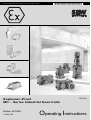
Explosion-Proof
MC... Series Industrial Gear Units
Edition 06/2006
11460628 / EN
GD210000
Operating Instructions
SEW-EURODRIVE – Driving the world
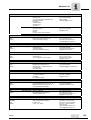
Contents
1
Important Notes on the Operating Instructions ............................................. 5
1.1 Important notes and designated use......................................................... 5
1.2 Explanation of symbols ............................................................................. 7
1.3 Notes on operation.................................................................................... 7
2
Safety Notes ...................................................................................................... 8
2.1 Introduction ............................................................................................... 8
2.2 General information .................................................................................. 8
2.3 Symbols on the gear unit ........................................................................ 10
2.4 Transporting industrial gear units............................................................ 11
2.5 Corrosion and surface protection............................................................ 15
2.6 Safety notes for use in potentially explosive areas ................................. 19
2.7 Checklists................................................................................................ 20
3
Gear Unit Design ............................................................................................. 21
3.1 Basic design of MC..P.. series industrial gear units................................ 21
3.2 Basic design of MC..R.. series industrial gear units ............................... 22
3.3 Unit designation, nameplates.................................................................. 23
3.4 Mounting positions .................................................................................. 25
3.5 Mounting surface .................................................................................... 25
3.6 Housing orientation M1 to M6 ................................................................. 26
3.7 Shaft positions ........................................................................................ 28
3.8 Direction of rotation................................................................................. 30
3.9 Lubrication of industrial gear units .......................................................... 34
4
Mechanical Installation................................................................................... 38
4.1 Required tools/resources ........................................................................ 38
4.2 Prerequisites for installation.................................................................... 38
4.3 Installing the gear unit............................................................................. 39
4.4 Gear unit foundation ............................................................................... 40
4.5 Mounting solid shaft gear units ............................................................... 47
4.6 Mounting/removing hollow shaft gears unit with keyed connection ........ 49
4.7 Mounting/removing hollow shaft gear units with shrink disc ................... 52
4.8 Mounting a motor with motor adapter ..................................................... 59
4.9 Installing industrial gear units in potentially explosive areas................... 62
4.10 Gear units in category II2GD .................................................................. 62
5
Mechanical Installation Options .................................................................... 63
5.1 Important installation instructions............................................................ 63
5.2 Mounting couplings ................................................................................. 66
5.3 FXM Backstop......................................................................................... 73
5.4 SHP shaft end pump............................................................................... 77
5.5 Installation with steel frame..................................................................... 80
5.6 Torque arm ............................................................................................. 81
5.7 Mounting a V-belt drive ........................................................................... 84
5.8 Oil heater ................................................................................................ 87
5.9 NTB temperature switch ......................................................................... 89
5.10 SPM Adapter........................................................................................... 91
5.11 Fan.......................................................................................................... 92
5.12 Flow monitor ........................................................................................... 93
5.13 Optical oil flow indicator .......................................................................... 94
5.14 Connecting the oil/water cooling system................................................. 95
5.15 Connecting the oil/air cooling system ..................................................... 95
5.16 Connecting the motor pump.................................................................... 95
Operating Instructions – Explosion-Proof MC.. Series Industrial Gear Units
3
Contents
4
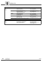
6
Startup.............................................................................................................. 96
6.1 Notes on startup ..................................................................................... 96
6.2 Gear unit startup .................................................................................... 97
6.3 Run-in period .......................................................................................... 98
6.4 Starting up gear units with backstop ....................................................... 98
6.5 Startup of industrial gear units with steel oil expansion tanks................. 99
6.6 Measuring the surface and oil temperatures......................................... 102
6.7 Starting up industrial gear units in potentially explosive areas ............. 102
6.8 Putting gear units out of operation ........................................................ 103
7
Inspection and maintenance........................................................................ 104
7.1 Inspection and maintenance intervals................................................... 104
7.2 Inspection and maintenance work on couplings ................................... 104
7.3 Lubricant change intervals .................................................................... 105
7.4 Checking the oil level ............................................................................ 106
7.5 Checking the oil consistency................................................................. 106
7.6 Changing the oil .................................................................................... 107
7.7 Cleaning the oil heater .......................................................................... 109
7.8 Vertical gear units with Drywell sealing system on the input shaft........ 110
8
Malfunctions .................................................................................................. 113
8.1 Gear unit malfunctions .......................................................................... 114
9
Mounting Positions...................................................................................... 115
9.1 Symbols used ....................................................................................... 115
9.2 Mounting positions of MC.P.. gear units ............................................... 116
9.3 Mounting position of MC.R.. series industrial gear units....................... 117
10
Design and Operating Notes........................................................................ 118
10.1 Guidelines for oil selection .................................................................... 118
10.2 Lubricant table ...................................................................................... 121
10.3 Lubricant fill quantities .......................................................................... 123
10.4 Sealing grease ...................................................................................... 124
11
Declaration of Conformity ............................................................................ 125
12
Index............................................................................................................... 127
Operating Instructions – Explosion-Proof MC.. Series Industrial Gear Units
Important Notes on the Operating Instructions
Important notes and designated use
1
Important Notes on the Operating Instructions
1.1
Important notes and designated use
1
Operating Instructions
Integral part of the product
The operating instructions are an integral part of the explosion-proof MC.. series
industrial gear units and contain important notes on operation and service. The operating instructions are written for all personnel carrying out assembly, installation, startup
and maintenance of the MC.. series industrial gear units.
Designated use
The MC.. series industrial gear units are intended for commercial and industrial systems
and may only be used in compliance with the information provided in SEWEURODRIVE technical documentation and the information given on the nameplate.
They correspond to valid standards and regulations and meet the requirements of EC
Directive 94/9/EC and the EC Directive for Machinery 98/37/EG.
Gear unit loads other than those specified, and applications other than industrial and
commercial systems can only be used after consultation with SEW-EURODRIVE.
Each application above and beyond these is considered non-designated use.
Qualified personnel
Explosion-proof MC.. series industrial gear units are a potential source of hazards for
personnel and equipment. Consequently, only trained personnel who are aware of the
potential hazards may perform assembly, installation, startup, and service work.
Personnel must be appropriately qualified for the task in hand and must be familiar with
the
•
assembly
•
installation
•
startup
•
operation
of the product.
Personnel must carefully read the operating instructions, in particular the safety notes
section, and make sure that they understand and comply with them.
Operating Instructions – Explosion-Proof MC.. Series Industrial Gear Units
5
Important Notes on the Operating Instructions
Important notes and designated use
1
Liability for defects
Incorrect handling or any action performed that is not specified in these operating
instructions could adversely affect the properties of the product. When this is the case,
you lose any right to claim against SEW-EURODRIVE GmbH & Co KG under limited
warranty.
Product names and trademarks
The brands and product names contained within these operating instructions are trademarks or registered trademarks of the titleholders.
Disposal
6
(Please observe current regulations):
•
Housing parts, gears, shafts, and roller bearings of the gear units must be disposed
of as steel scrap. This also applies to gray-cast iron parts if there is no separate
collection for them.
•
Collect waste oil and dispose of it in the proper manner.
Operating Instructions – Explosion-Proof MC.. Series Industrial Gear Units
Important Notes on the Operating Instructions
Explanation of symbols
1.2
1
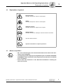
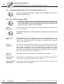
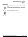
Explanation of symbols
Electrical hazard
Possible consequences: Severe or fatal injuries
Hazard
Possible consequences: Severe or fatal injuries
Hazardous situation
Possible consequences: Slight or minor injuries
Harmful situation
Possible consequences: Damage to the drive and the environment
Tips and useful information
Important information on explosion protection
1.3
Notes on operation
•
MC.. series industrial gear units are delivered without oil fill. Refer to the information on the nameplate.
•
The mounting position may only be changed after prior consultation with SEWEURODRIVE. ATEX certification and the guarantee will become void without
prior consultation.
•
Please follow the instructions in the "Mechanical Installation / Installing the
Gear Unit" section.
Operating Instructions – Explosion-Proof MC.. Series Industrial Gear Units
7
Safety Notes
Introduction
2
2
Safety Notes
2.1
Introduction
2.2
•
The following safety notes are concerned with the use of MC.. series industrial
gear units.
•
Also note the supplementary safety notes in the individual sections of these
operating instructions.
General information
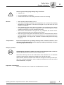
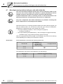
Risk of burns
Touching the gear unit before it has cooled down will result in burns.
Never touch the gear unit during operation or in the cool down phase once the unit has
been switched off. The cool down phase is at least 8 hours long.
Never install damaged products or put them into operation.
Please submit a complaint to the shipping company immediately in the event of damage.
During or after operation, industrial gear units and motors have:
•
Live parts
•
Moving parts
•
Hot surfaces (may be the case)
Only qualified personnel may carry out the following work:
•
Installation / Assembly
•
Connection
•
Startup
•
Maintenance
•
Servicing
The following information and documents must be observed during this work:
8
•
Relevant operating instructions and wiring diagrams
•
Warning and safety signs on the gear unit
•
System-specific regulations and requirements
•
National / regional regulations governing safety and the prevention of accidents
Operating Instructions – Explosion-Proof MC.. Series Industrial Gear Units
Safety Notes
General information
2
Serious injuries and property damage may result from:
General
Transportation
•
Improper use
•
Incorrect installation or operation
•
Unauthorized removal of necessary protective covers or the housing
•
Work carefully and keep safety in mind.
•
If you observe changes in the gear unit during operation, an increase in the operating
temperature or a difference in the sound of the gear unit, put the drive unit out of
operation immediately.
•
When installing the gear unit in devices or systems, the manufacturer of the device
or system is obligated to include the regulations, notes, and descriptions in these
operating instructions in his own operating instructions.
•
Observe the notes attached to the gear unit, e.g. nameplate and direction arrow.
They must be free of paint or dirt. Replace missing signs.
•
Work on the gear unit only when the machine is not in use. Prevent the drive unit from
being accidentally switched on by locking the keyswitch or removing the fuses from
the power supply. Put a sign at the on-switch to warn that the gear unit is being
worked on.
Inspect the shipment for any damage that may have occurred in transit as soon
as you receive the delivery. Inform the shipping company immediately. It may be
necessary to preclude startup.
Startup / operation
Check that the direction of rotation is correct in the decoupled state. Listen for
unusual grinding noises when you are turning the shaft.
Secure the shaft keys for the test mode without drive elements. Do not deactivate
monitoring and protection equipment inoperative even for the test mode.
When in doubt, switch off the main motor whenever changes occur during normal operation (e.g. increased temperature, noise, vibration). Determine the cause and contact
SEW-EURODRIVE, if required.
Inspection / maintenance
Follow the instructions in the "Inspection and Maintenance" section.
Operating Instructions – Explosion-Proof MC.. Series Industrial Gear Units
9
Safety Notes
Symbols on the gear unit
2
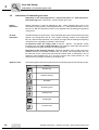
2.3
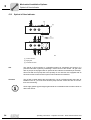
Symbols on the gear unit
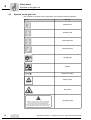
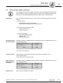
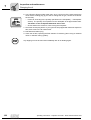
The symbols on the gear unit must be noted. They have the following meaning:
Symbol
Meaning
Breather valve
Oil filling screw
Oil draining screw
Lubrication points
MIN
Oil sight glass
Dipstick
MIN
Direction of rotation
Delivery status
GELIEFERT
OHNE ÖL
Hot surfaces
GEAR UNIT IS VPI ANTI-RUST TREATED. COVER AND
PLUG OF GEAR UNIT MUST NOT TO BE OPEND AND
GEAR UNIT MUST NOT ROTATED BEFORE STARTUP. BEFORE START-UP THE PROTECTIVE PLUG MUST BE
REMOVED AND REPLACED BY ENCLOSED AIR VALVE.
10
Long-term storage
Operating Instructions – Explosion-Proof MC.. Series Industrial Gear Units
Safety Notes
Transporting industrial gear units
2.4
2
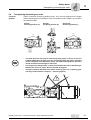
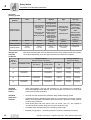
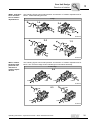
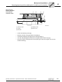
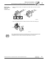
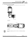
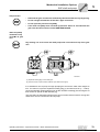
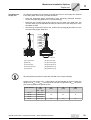
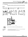
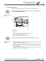
Transporting industrial gear units
Transport
eyebolts
Tighten screwed in transport eyebolts [1] firmly. They are only designed for the weight
of the industrial gear unit including the motor connected via motor adapter; do not attach
any additional loads.
Vertical
mounting position (V)
Upright
mounting position (E)
Horizontal
mounting position (L)
[1]
[1]
[1]
[1]
51375AXX
•
The main gear unit may only be lifted using lifting ropes or chains on the two
eyebolts attached to the main gear unit. The weight of the gear unit is indicated
on the nameplate or the dimension sheet. The loads and regulations specified
in that document must always be observed.
•
The length of the lifting chains or ropes must be dimensioned so that the angle
between the chains or ropes does not exceed 45 degrees.
•
Transport eyebolts attached to the motor, auxiliary gear unit, or primary gear
unit may not be used for transport (→ following figures).
52086AXX
Operating Instructions – Explosion-Proof MC.. Series Industrial Gear Units
11
Safety Notes
Transporting industrial gear units
2
52112AXX
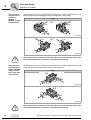
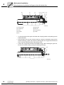
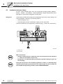
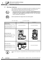
•
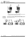
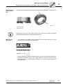
Transporting
MC.. industrial
gear units with
motor adapter
[1]
Use suitable, sufficiently rated means of transportation if necessary. Remove
securing devices used for transportation prior to startup.
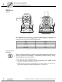
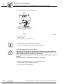
Industrial gear units of the MC.P.. /MC.R.. series with motor adapter (→ following
figure) may only be transported using lifting ropes/chains [2] or lifting belts [1] at an
angle of 90 (vertical) to 70 degrees.
90°-70°
[2]
[1]
[2]
<70°
52110AXX
12
Operating Instructions – Explosion-Proof MC.. Series Industrial Gear Units
Safety Notes
Transporting industrial gear units
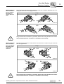
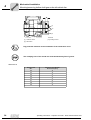
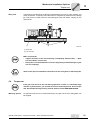
Transporting
MC.. industrial
gear units on a
base plate
2
Industrial gear units of the MC.. series on a base plate (→ following figure) may only
be transported with the lifting ropes [1] or chains (90 degree angle) vertically secured
to the base frame:
[1]
[1]
90
90
°
°
51376AXX
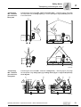
Transporting
MC.. industrial
gear units on a
swing base
Industrial gear units of the MC.. series on a swing base (→ following figure) may only
be transported using lifting ropes [1] or lifting chains [2] at an angle of 90 (vertical)
to 70 degrees.
[1]
[1]
[2]
90°-70°
[2]
<70°
52081AXX
Operating Instructions – Explosion-Proof MC.. Series Industrial Gear Units
13
2
Safety Notes
Transporting industrial gear units
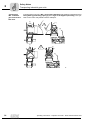
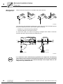
Transporting
MC.. industrial
gear units with Vbelt drive
Industrial gear units of the MC.. series with V-belt drive may only be transported using
lifting belts [1] and lifting ropes [2] at an angle of 90 degrees (vertically). The eyebolts on the motor may not be used for transport.
[1]
[1]
90
°
90
°
[2]
[1]
[1]
[2]
52111AXX
14
Operating Instructions – Explosion-Proof MC.. Series Industrial Gear Units
Safety Notes
Corrosion and surface protection
2.5
2
Corrosion and surface protection
The information in this section applies only for MC.. series industrial gear units that have
been installed in Europe. It is possible that other regions use a different painting system.
Contact your local SEW-EURODRIVE assembly plant for MC.. industrial drives.
Introduction
The corrosion and surface protection of gear units comprises the following three basic
features:
1. Painting system
•
•
Standard painting system K7 E160/2
High-resistance painting system E260/3 optional
2. Gear unit corrosion protection with
•
•
interior protection and
exterior protection
3. Gear unit packaging
•
•
•
Standard painting
system K7 E160/2
Standard packaging (pallet)
Wooden crate
Seaworthy packaging
Painting according to TEKNOS EPOXY SYSTEM K7 based on TEKNOPLAST HS 150
high-solid epoxy paint.
Two-layer system K7 E 160/2
Thickness
•
Epoxy primer
60 µm
•
Teknoplast HS 150
100 µm
TOTAL
160 µm
Color: RAL 7031, blue gray
Protective covers
Powder coating, epoxy-based coat paint (EP) is used for protective covers.
Coat thickness: 65 µm
Color: TM 1310 PK, warning in yellow
High-resistance
painting system
K7 E 260/3
Painting according to TEKNOS EPOXY SYSTEM K7 based on TEKNOPLAST HS 150
high-solid epoxy paint.
E 260/3 Three-layer system
•
Epoxy primer
•
Teknoplast HS 150
Total thickness
Optional color
Thickness
60 µm
2x100 µm
260 µm
Other colors are available on request.
Operating Instructions – Explosion-Proof MC.. Series Industrial Gear Units
15
Safety Notes
Corrosion and surface protection
2
Using the
painting system
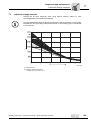
Environmental
pollution
None
Low
High
Production halls
with high humidity levels and low
air contamination.
Unheated buildings where condensation can
build up.
Typical environmental conditions
Atmospheres with
low pollution.
Mostly rural areas.
City and industrial
atmospheres,
moderate contamination with sulphur dioxide.
Coastal areas with
a low salt load.
Very high
Industrial areas
and coastal areas
with a moderate
salt load.
Chemical plants
Buildings or areas
with almost permanent condensation and high
levels of contamination.
Industrial areas
with high humidity and aggressive
atmospheres
Assembly
Indoors
Indoors
Indoors or
outdoors
Indoors or
outdoors
Indoors or
outdoors
Relative humidity
< 90 %
Up to 95 %
Up to 100 %
Up to 100 %
Up to 100 %
Recommended
painting system
Standard painting
system
K7 E160/2
Standard painting
system
K7 E160/2
Standard painting
system
K7 E160/2
High-resistance
painting system
K7 E260/3
Contact SEWEURODRIVE
Storage and
transport
conditions
Storage
period: Up to
... months
MC series industrial gear units are delivered without oil fill. Different protection systems
are required depending on the storage period and environmental conditions:
Storage Conditions
Gear Unit Corrosion Protection
12
Land transport
Sea transport
Long-term
protection
Standard
packaging
Seaworthy
packaging
Contact SEWEURODRIVE
Long-term
protection
Standard
packaging
Seaworthy
packaging
Contact SEWEURODRIVE
Contact SEWEURODRIVE
Long-term
protection
Standard
packaging
Seaworthy
packaging
Long-term
protection
Contact SEWEURODRIVE
Long-term
protection
Standard
packaging
Seaworthy
packaging
INDOORS, heated
(0 to +20°C)
OUTDOORS at
the sea, roofed
INDOORS at the
sea
Standard protection
Standard protection
Contact SEWEURODRIVE
Contact SEWEURODRIVE
Standard protection
Long-term protection
Contact SEWEURODRIVE
24
36
Transport conditions
Gear unit packaging
OUTDOORS, roofed
6
16
Medium
Standard
protection /
indoors
•
Gear units undergo a test run with protective oil. The protective oil is drained by
SEW-EURODRIVE before dispatch. The remaining layer of protective oil on the inner
parts serves as basic protection.
Standard
protection /
outdoors
•
Oil seals and seal surfaces are protected using suitable bearing grease.
•
Unpainted surfaces (including spare parts) are covered with a protective coating.
Before other equipment is mounted to these surfaces, the protective coating must be
removed using a solvent.
•
Small spare parts and loose pieces, such as screws, nuts, etc., are supplied in
corrosion protection plastic bags (VCI corrosion protection bag).
•
Threaded holes and blind holes are covered by plastic plugs.
•
Breather plug (position → "Mounting Positions" section) installed at the factory.
Operating Instructions – Explosion-Proof MC.. Series Industrial Gear Units
Safety Notes
Corrosion and surface protection
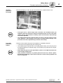
Standard
protection /
packaging
2
Standard packaging is used: the gear unit is delivered on a pallet without cover.
55871AXX
Long-term
protection /
indoors
•
If the gear unit is stored longer than 6 months, we recommend that you
regularly check the protective coating of unpainted areas as well as the paint
coating. Areas with protective coating or paint that has been removed may
have to be repainted.
•
The output shaft must be rotated at least one turn so that the position of the
roller elements in the bearings of the input and output shafts changes. This
procedure has to be repeated every 6 months until startup.
Protection of the inside of the gear unit in addition to "standard protection:"
•
A VPI solvent is sprayed through the oil filling hole.
•
The breather plug is replaced with a screw plug (before startup, the screw plug must
be replaced again by the breather plug). The breather plug is attached to the gear
unit separately.
•
Never open the gear unit near open flames, sparks, or hot objects because the
solvent vapors might ignite.
•
Take preventive measures to protect personnel from the solvent vapors.
Exclude the possibility of open flames when the solvent is being applied and
when it evaporates.
Operating Instructions – Explosion-Proof MC.. Series Industrial Gear Units
17
Safety Notes
Corrosion and surface protection
2
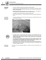
Long-term
protection /
outdoors
Long-term
protection /
packaging
•
Oil seals and sealing surfaces are protected by suitable grease.
•
Unpainted surfaces (including spare parts) are covered with a protective coating.
Before other equipment is mounted to these surfaces, the protective coating must be
removed using a solvent.
•
Small spare parts and loose pieces, such as screws, nuts, etc., are supplied in
corrosion protection plastic bags (VCI corrosion protection bag).
•
Threaded holes and blind holes are covered by plastic plugs.
•
The breather plug (position → "Mounting Positions" section) is already installed at the
factory.
•
Seaworthy packaging is used: the gear unit is packed in a seaworthy wooden crate
and delivered on a pallet.
57585AXX
Alternative
packaging
18
•
If the gear unit is stored longer than 6 months, we recommend that you
regularly check the protective coating of unpainted areas as well as the paint
coating. Areas with protective coating or paint that has been removed may
have to be repainted.
•
The output shaft must be rotated at least one turn so that the position of the
roller elements in the bearings of the input and output shafts changes. This
procedure has to be repeated every 6 months until startup.
•
Long-term protection of the gear unit interior with the VPI solvent has to be repeated every 24 to 36 months until startup (according to the Storage and
Transport Conditions table).
The gear unit can be optionally supplied in a wooden crate with standard gear unit
protection.
Operating Instructions – Explosion-Proof MC.. Series Industrial Gear Units
Safety Notes
Safety notes for use in potentially explosive areas
2.6
2
Safety notes for use in potentially explosive areas
Explosive gas mixtures or dust concentrations in combination with hot, live,
moving parts of electrical machinery can cause serious injury or death.
Installation, connection, startup, maintenance and repair work on gear
units/gearmotors and the optional electrical components may only be performed
by qualified personnel while taking the following into account:
Designated use
•
These operating instructions
•
The warning and safety signs on the gear unit/gearmotor
•
All other project planning documents, operating instructions, and wiring diagrams
included with the drive
•
The regulations and requirements specific to the system
•
Currently valid national/regional regulations (explosion protection, safety, prevention
of accidents)
The gear units/gearmotors are intended for industrial systems and may only be used in
accordance with the information provided in the technical documentation of SEWEURODRIVE and the information given on the nameplate. They meet the requirements
set forth in Directive 94/9/EEC and comply with the applicable standards and regulations.
A drive motor connected to the gear unit may only be operated under the conditions
described in the "Starting up gear units in potentially explosive areas" section.
A motor mounted to a gear unit by means of an adapter may only be operated on
a frequency inverter when the data on the gear unit nameplate is complied with.
A motor connected to a gear unit by means of an adapter or belt may only be
operated when the data on the gear unit nameplate is complied with.
Make sure that there are no corrosive chemicals that could damage the coating
and seals in the immediate area.
Operating Instructions – Explosion-Proof MC.. Series Industrial Gear Units
19
Safety Notes
Checklists
2
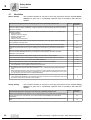
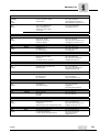
2.7
Checklists
Before startup
This checklist contains an overview of all of the points that must be checked before
startup of a gear unit in a potentially explosive area in accordance with Directive
94/9/EC.
Check the following points before starting up a gear unit in a potentially explosive area
Check
Inspect the shipment for any damage that may have occurred in transit as soon as you receive the delivery.
Inform the shipping company immediately. It may be necessary to preclude startup. Remove any transport
fixtures prior to startup.
2
Compare the data on the nameplate of the drive with the specifications for operation in a potentially explosive area on location:
• Equipment group
• Explosion protection category
• Explosion protection zone
• Temperature class
• Maximum surface temperature
3.3 and 4.10
Have arrangements been made to prevent explosive atmospheres, oils, acids, gases, vapors or radiation
during installation of the gear unit?
4.2
Does the ambient temperature comply with the specifications (in accordance with the lubrication table)?
10
Have measures been taken to ensure that the gear units are sufficiently ventilated and that they are not
heated by an external heat source (e.g. the coupling)? The cooling air may not exceed a temperature of
40°C.
4.3 and 4.10
Does the mounting position correspond to the specification on the nameplate?
Note: Contact SEW-EURODRIVE before you change the mounting position. Otherwise, the ATEX
certification may not be valid.
4.3
Does the oil level for this mounting position comply with the information on the nameplate?
4.3
Do you have ready access to all oil filling and oil draining screws and the breather plug and ventilation?
4.3
Do all installed drives and drive components have ATEX certification?
4 and 5
Have you checked that the values on the nameplate of the gear unit are not exceeded?
5
When installing gear units with hollow shaft and shrink disc:
• Was the protective cover installed according to the instructions?
4.6 and 4.7
When installing a motor to the input shaft using a V-belt drive:
• Does the belt have sufficient attenuation resistance (< 109 Ω ) between the input shaft and the motor
shaft?
• Before installing a protective cover: Has the manufacturer of the protective cover performed a risk analysis to prove that no sources of ignition or combustion (e.g. risk of sparks from grinding) can occur? (If you
are not using the protective cover from SEW-EURODRIVE)
5.7
For motors with mains operation:
• Check that the data specified on the nameplate of the gear unit and the motor corresponds to real conditions at the location where the drive is to be installed.
5
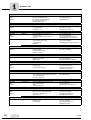
During startup
This checklist contains an overview of all of the points that must be checked during
startup of a gear unit in a potentially explosive area in accordance with Directive
94/9/EC.
Check the following points during gear unit start up in a potentially explosive area
20
Information
in section ...
Check
Information
in section ...
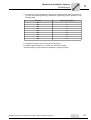
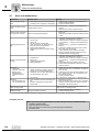
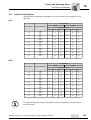
Measure the oil temperature after approx. 6 hours. The temperature may not differ from the ambient temperature by more than 70 K. If the value is > 70 K, switch the drive off immediately and contact SEWEURODRIVE.
5.4
Measure the oil temperature. Add 10 K to the measured value. Base the oil replacement intervals on this
value.
5.4
Operating Instructions – Explosion-Proof MC.. Series Industrial Gear Units
Gear Unit Design
Basic design of MC..P.. series industrial gear units
3
3
Gear Unit Design
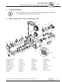
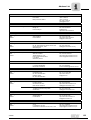
The following figures serve as an assignment aid for the spare parts list. Discrepancies
may exist depending on the gear unit size and version.
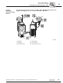
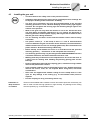
3.1
Basic design of MC..P.. series industrial gear units
[070]
[010]
[180]
[199]
[195]
[110]
[299]
[295]
[725]
[025]
[243]
[210]
[130]
[331]
[725]
[131]
[342]
[100]
[395]
[310]
[301]
[110]
[195]
[399]
[231]
[015]
[210]
[201]
[410]
[443]
[495 ]
[295]
[242]
[401]
MC2P..
[430]
[411]
[040]
[495]
[340]
[480]
[438]
[310]
[395]
[434]
[001]
[075]
[342]
51718AXX
[001] Gear unit housing
[131] Key
[299] Wheel
[410] Bearings
[010] Bearing cover
[180] Oil seal
[301] Pinion shaft
[411] Roller bearings
[015] Bearing cover
[195] Shim
[310] Bearing
[430] Key
[025] Bearing cover
[199] Final gear
[331] Key
[434] Cover
[040] Bearing cover
[201] Pinion shaft
[340] Spacer
[438] Socket
[070] Gear cover plate
[210] Bearing
[342] Spacer
[443] Distance bushing
[075] Cover plate
[231] Key
[395] Shim
[480] Oil seal
[100] Output shaft
[242] Spacer
[399] Gearwheel
[495] Shim
[110] Bearing
[243] Spacer
[401] Input shaft
[725] Lifting eyebolt
[130] Key
[295] Shim
Operating Instructions – Explosion-Proof MC.. Series Industrial Gear Units
21
Gear Unit Design
Basic design of MC..R.. series industrial gear units
3
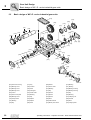
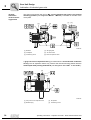
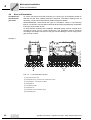
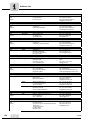
3.2
Basic design of MC..R.. series industrial gear units
[070]
[010]
[180]
[199]
[195]
[110]
[131]
[100]
[110]
[243]
[295]
[299]
[195]
[725]
[015]
[210]
[331]
[342] [25]
[725]
[395]
[310]
[301]
[341]
[231]
[210]
[340]
[399]
[430]
[201]
[410]
[295]
[242]
[495]
[001]
[401]
[310]
[422]
[395]
[080]
[342]
[025]
[423]
[480]
[040]
[411]
[470]
[436]
51399AXX
[001] Gear unit housing
22
[131] Key
[299] Wheel
[410] Bearing
[010] Bearing cover
[180] Oil seal
[301] Pinion shaft
[411] Bearing
[015] Bearing cover
[195] Shim
[310] Bearing
[422] Bearing bushing
[025] Bearing cover
[199] Final gear
[331] Key
[423] Bearing bushing
[040] Cover
[201] Pinion shaft
[340] Spacer
[430] Key
[070] Gear cover plate
[210] Bearing
[341] Spacer
[436] Bushing
[080] Bearing cover
[231] Key
[342] Spacer
[470] Clamping nut
[100] Output shaft
[242] Spacer
[395] Shim
[480] Oil seal
[110] Bearing
[243] Spacer
[399] Helical-bevel
[495] Shim
[130] Key
[295] Shim
[401] Bevel pinion shaft
[725] Lifting eyebolt
Operating Instructions – Explosion-Proof MC.. Series Industrial Gear Units
Gear Unit Design
Unit designation, nameplates
3.3
3
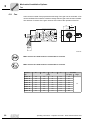
Unit designation, nameplates
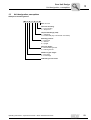
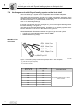
Example of unit designation
MC 2
R
L
S
F
05
Size: 02 to 09
Gear unit mounting:
F = Foot mounting
T = Torque arm
Output shaft design (LSS):
S = Solid shaft
H = Hollow shaft (key or shrink disc connection)
Mounting position:
L = Horizontal
V = Vertical
E = Upright
Gear unit design:
R = Bevel-helical gear unit
P = Helical gear unit
Number of gear stages:
2 = Two-stage
3 = Three-stage
Industrial gear unit series
Operating Instructions – Explosion-Proof MC.. Series Industrial Gear Units
23
3
Gear Unit Design
Unit designation, nameplates
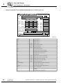
Example: Nameplate of the SEW-EURODRIVE MC series industrial gear unit
SEW-EURODRIVE
Bruchsal / Germany
Type MC3RLSF02
Nr. 1 03 30764647
Nr. 2
K3463
1:
20.3123
norm.
min.
max.
i
PK1 [kW]
16.5
16.5
16.5
FS
MK2 [kNm]
2.04
2.04
2.04
FR1
[kN] 0
n1
[1/min]
1500
1500
1500
FR2
[kN] 0
n2
[1/min]
73.8
73.8
73.8
FA1
[kN] 0
Operation instructione have to be observed! FA2
[kN] 0
Made in SEW -Finland
3.64
Mass [kg] 219
II3GD c, k T4/120 °C IP65
Qty of greasing points 2 Fans 0
Synthetic Oil ISO VG 460 EPPAO - 7 ltr.
Lubricant
Year 2003
IM: M1 - F1 // TU = 0 - 40 °C // FSA GmbH EUCode0588
56625AXX
Design
Unit designation
No. 1
Serial number 1
No. 2
Serial number 2
PK1
[KW]
Gear unit force
MK2
[kNm]
Gear unit output torque
n1
[rpm]
Input speed (HSS)
n2
[rpm]
Output speed (LSS)
Norm.
Normal operating point
Min.
Operating point at minimum speed
Max.
Operating point at maximum speed
i
Exact gear unit reduction ratio
FS
24
Service factor
FR1
[kN]
Actual overhung load on input shaft
FR2
[kN]
Actual overhung load on output shaft
FA1
[kN]
Actual axial load on input shaft
FA2
[kN]
Actual axial load on output shaft
Weight
[kg]
Weight of the gear unit
No. of lube points:
Number of points that require re-greasing
Fan
Number of fans installed
Lubricant
Oil grade and viscosity class/oil volume
Year
Year of construction
IM
Mounting position: Housing alignment and mounting surface
variants
TU
Permitted ambient temperature
Operating Instructions – Explosion-Proof MC.. Series Industrial Gear Units
Gear Unit Design
Mounting positions
3.4
3
Mounting positions
The following features uniquely define the mounting position and corresponding design
of MC.. series gear units:
•
Mounting surface (F1 to F6) → Section 3.5
•
Housing orientation (M1 to M6) → Section 3.6
In addition, the shaft position (0 to 4) has to be defined → Section 3.7.
The horizontal output shaft (L), vertical output shaft (V) and upright mounting (E) gear
unit designs refer to the housing orientation.
3.5
Mounting surface
Definition
The mounting surface is defined as the surface(s) of the foot or flange mounted gear unit
that the customer's machine is mounted on.
Designations
Six different mounting surfaces were defined (designation "F1" to "F6"):
F4
F1
F2
F5
F6
F3
54498AXX
Operating Instructions – Explosion-Proof MC.. Series Industrial Gear Units
25
Gear Unit Design
Housing orientation M1 to M6
3
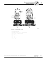
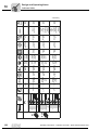
3.6
Housing orientation M1 to M6
The housing orientation is defined as the position of the housing in space and is identified using the designations M1 to M6.
Each housing orientation corresponds to a certain
•
Gear unit design (L, V, E)
•
Standard mounting surface (F1 to F6)
The housing orientation is defined separately for
•
Helical gear units MC.P..
•
Bevel-helical gear units MC.R..
Unless specified otherwise, the standard dependency of
•
gear unit design and
•
housing orientation, and
•
mounting surface
is as follows (for foot mounted gear units):
Standard assignment of gear unit
design and
mounting surface
MC..PL:
M1, F1
MC..PV:
M5, F3
MC..PE:
M4, F6
MC..RL:
M1, F1
MC..RV:
M5, F3
MC..RE:
M4, F6
For gear units with mounting flange on the output shaft, the standard position of the
flange depends on the shaft position of the output shaft unless specified otherwise:
26
•
Shaft position 3 → Output shaft mounting flange F3
•
Shaft position 4 → Output shaft mounting flange F4
Operating Instructions – Explosion-Proof MC.. Series Industrial Gear Units
Gear Unit Design
Housing orientation M1 to M6
3
Housing
orientation and
standard mounting surface
M1
M1
4
1
3
MC..PE
1
F1
M2
4
1
F3
M2
MC..PV
F3
2
MC..PV
2
M6
MC..PL
M6
MC..PL
MC..PE
3
1
F6
3
4
3
4
3
F3
2
2
2
3
4
MC..PE
1
4
F3
1
M4
2
2
M4
MC..PE
4
4
2
4
1
1
3
F1
4
M5
3
4
F3
F3
1
3
F6
MC..PV
3
MC..PV
3
1
MC..PL
M3
1
M5
M3
3
2
F3
MC..PL
M1
F3
4
M1
M2
MC..RL
0
MC..RL
MC..RE
F6
4
M6
0
MC..RV
3
F3
2
2
M6
2
4
1
2
F3
0
4
MC..RV
0
4
3
3
M2
MC..RE
3
3
F3
F1
3
0
4
M4
F3
4
0
M4
MC..RE
0
4
0
0
4
MC..RE
4
F3
4
0
M5
F6
3
3
F1
MC..RV
4
4
3
F3
3
4
3
M3
0
MC..RL
F3
M5
MC..RV
M3
MC..RL
3
F3
0
•
The gear units marked in gray are standard design.
•
Other mounting surfaces are possible in conjunction with a certain housing
orientation. Refer to the order-specific dimension drawing.
The housing orientation and/or mounting surface may not differ from the order.
Operating Instructions – Explosion-Proof MC.. Series Industrial Gear Units
27
Gear Unit Design
Shaft positions
3
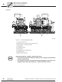
3.7
Shaft positions
The shaft positions (0, 1, 2, 3, 4) and rotation direction dependencies shown in the
following figures apply to solid shaft and hollow shaft design output shafts (LSS). For
other shaft positions or gear units with backstop, contact SEW-EURODRIVE.
The following mounting positions (0, 1, 2, 3, 4) are possible:
Shaft positions MC.P.S..
Housing orientation
M1
M5
Horizontal output shaft (L)
Vertical output shaft (V)
M4
Gear unit design
2
4
2
Upright mounted (E)
2
4
1
4
3
1
1
3
3
Shaft positions MC.P.H..
Housing orientation
M1
M5
Horizontal output shaft (L)
Vertical output shaft (V)
M4
Gear unit design
Upright mounted (E)
2
3
2
4
2
4
1
3
3
28
1
3
4
1
3
3
Operating Instructions – Explosion-Proof MC.. Series Industrial Gear Units
Gear Unit Design
Shaft positions
3
Shaft positions MC.R.S..
Housing orientation
M1
M5
M4
Gear unit design
Horizontal output shaft (L)
Vertical output shaft (V)
Upright mounted (E)
4
0
0
4
0
4
3
3
3
Shaft positions MC.R.H..
Housing orientation
M1
M5
M4
Horizontal output shaft (L)
Vertical output shaft (V)
3
Gear unit design
4
Upright mounted (E)
4
0
0
0
4
3
3
3
Operating Instructions – Explosion-Proof MC.. Series Industrial Gear Units
3
3
29
Gear Unit Design
Direction of rotation
3
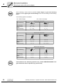
3.8
Direction of rotation
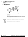
Directions of
rotation
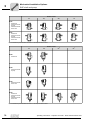
The directions of rotation of the outputs shaft (LSS) are defined as follows:
Gear unit design
Direction
of rotation
MC.P.S..
MC.R.S..
MC.P.H..
MC.R.H..
Clockwise
(CW)
52036AXX
51383AXX
52037AXX
51386AXX
Counterclockwise
(CCW)
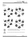
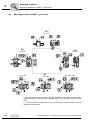
MC2P.. shaft
positions and
direction of
rotation dependencies
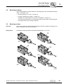
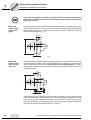
The following figures show shaft positions and direction of rotation dependencies for
MC2P.. series industrial gear units.
2-stage
1-4
2-4
CCW
CW
CW
CW
CCW
CW
CCW
CCW
51391AXX
2-3
CCW
CCW
CW
CW
1-3
CCW
CW
CW
CCW
51392AXX
30
Operating Instructions – Explosion-Proof MC.. Series Industrial Gear Units
Gear Unit Design
Direction of rotation
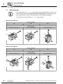
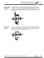
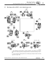
MC3P.. shaft positions and direction of rotation
dependencies
3
The following figures show shaft positions and direction of rotation dependencies for
MC3P.. series industrial gear units.
3-stage
1-4
2-4
CCW
CW
CW
CW
CCW
CW
CCW
CCW
52038AXX
2-3
1-3
CCW
CCW
CW
CW
CW
CCW
CW
CCW
52039AXX
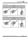
MC.R.. without
backstop shaft
positions and
direction of
rotation dependencies
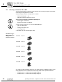
The following figures show shaft positions and direction of rotation dependencies for
MC.R.. two- and three-stage series industrial gear units without backstop.
2- and 3-stage
0-4
CW
CW
CCW
CCW
CCW
CW
CCW
CW
51389AXX
CCW
0-3
CCW
CW
CW
CCW
CW
CCW
CW
51390AXX
Operating Instructions – Explosion-Proof MC.. Series Industrial Gear Units
31
3
Gear Unit Design
Direction of rotation
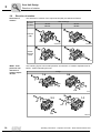
Shaft positions
and direction of
rotation of
MC2RS.. /
MC2RH.. keyway
with backstop
Following figures show the shaft positions and direction of rotation dependencies for 2stage gear units with backstop type MC.RS..and MC.RH.. with keyway.
2-stage
0-4
CW
CW
CCW
CCW
CW
CW
CCW
CCW
55950AXX
CCW
0-3
CCW
CW
CCW
CW
CCW
CW
CW
55951AXX
Only one direction of rotation is possible, which has to be specified in the order.
The permitted direction of rotation is indicated on the housing.
Shaft positions
and direction of
rotation MC2RH..
/SD gear units
with shrink disc
and backstop
Following figures show the shaft positions and direction of rotation dependencies for 2stage gear units with backstop type MC.RS.. and shrink disc.
2-stage
0-4
CW
CCW
CCW
CW
55952AXX
0-3
CCW
CW
CW
CCW
55953AXX
Only one direction of rotation is possible, which has to be specified in the order.
The permitted direction of rotation is indicated on the housing.
32
Operating Instructions – Explosion-Proof MC.. Series Industrial Gear Units
Gear Unit Design
Direction of rotation
MC3R shaft positions and direction of rotation,
backstop on
driven machine
end.
3
Following figures show the shaft positions and direction of rotation dependencies for 3stage gear units with backstop type MC.3R..
3-stage
0-4
CW
CCW
CW
CCW
CCW
CW
CCW
CW
55954AXX
0-3
CW
CCW
CCW
CW
CW
CW
CCW
CCW
55956AXX
Only one direction of rotation is possible, which has to be specified in the order.
The permitted direction of rotation is indicated on the housing.
MC3R shaft positions and directions of rotation,
backstop opposite driven
machine
Following figures show the shaft positions and directions of rotation for gear units with
backstop type MC3R.
3-stage
0-4
CW
CW
CCW
CCW
CW
CW
CCW
CCW
55957AXX
CCW
0-3
CCW
CW
CW
CCW
CW
CCW
CW
55958AXX
Only one direction of rotation is possible, which has to be specified in the order.
The permitted direction of rotation is indicated on the housing.
Operating Instructions – Explosion-Proof MC.. Series Industrial Gear Units
33
Gear Unit Design
Lubrication of industrial gear units
3
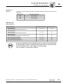
3.9
Lubrication of industrial gear units
Depending on the mounting position, "splash lubrication" or "bath lubrication"
lubrication types are used for MC.. series industrial gear units.
Splash
lubrication
Splash lubrication is used as standard for MC.. series industrial gear units in the
horizontal mounting position (unit designation MC..L..). With splash lubrication, the oil
level is low. With this lubrication method, oil is splashed onto the bearings and gearing
components.
Oil bath
lubrication
Oil bath lubrication is used for MC.. series industrial gear units in the horizontal mounting
position (unit designation MC..V..) and upright mounting position (unit designation
MC..E..). With oil bath lubrication, the oil level is so high that the bearings and gearing
components are completely immersed in the lubricant.
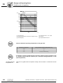
Oil expansion tanks are always used for MC.PV.., MC.RV.,. and MC.RE.. series
industrial gear units with oil bath lubrication. Oil expansion tanks allow the lubricant
to expand when the gear unit heats up during operation.
Regardless of the mounting position, a steel oil expansion tank is used if the unit is
installed outdoors and ambient conditions are very humid. The oil expansion tank can
be used both for the version with solid shaft and hollow shaft. A membrane in the oil
expansion tank separates the oil in the gear unit from the humid ambient air. This
ensures that no humidity can build up in the gear unit.
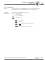
Symbols used
The following table shows the symbols used in the following figures and what they mean:
Symbol
Meaning
Breather plug
Inspection opening
Oil dipstick
Oil draining screw
Oil filling screw
Oil sight glass
Air outlet screw
34
Operating Instructions – Explosion-Proof MC.. Series Industrial Gear Units
Gear Unit Design
Lubrication of industrial gear units
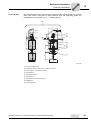
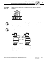
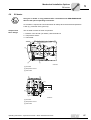
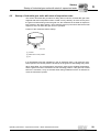
Oil bath
lubrication
upright mounting
position
3
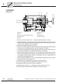
The steel oil expansion tank (6) is used for MC.. series industrial gear units in the
upright mounting position (unit designation MC.PE.. or MC..RE..).
[6]
[2]
[1]
[5]
[4]
[3]
51586AXX
[1] Breather
[4] Oil sight glass
[2] Oil dipstick
[5] Air outlet screw
[3] Oil draining screw
[6] Steel oil expansion tank
Operating Instructions – Explosion-Proof MC.. Series Industrial Gear Units
35
Gear Unit Design
Lubrication of industrial gear units
3
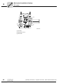
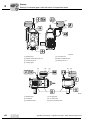
Oil bath
lubrication
vertical mounting position
The steel oil expansion tank (6) for MC.. series industrial gear units in the vertical
mounting position (unit designation MC.PV.. / MC.RV..) is located on the side of the
cover plate.
[2]
[6]
[1]
[4]
[5]
[3]
51588AXX
[1] Breather
[4] Oil sight glass
[2] Oil dipstick
[5] Air outlet screw
[3] Oil draining screw
[6] Steel oil expansion tank
A gray-cast iron oil expansion tank [1] is used when the environmental conditions
are dry. This oil expansion tank is only used for the vertical mounting position with the
solid output shaft pointing downwards (unit designation MC.PVSF.. or MC.RVSF..).
[2]
[1]
[3]
[4]
51589AXX
36
[1] Gray-cast iron oil expansion tank
[3] Oil dipstick
[2] Breather plug
[4] Oil draining screw
Operating Instructions – Explosion-Proof MC.. Series Industrial Gear Units
Gear Unit Design
Lubrication of industrial gear units
Pressure
lubrication
3
You can specify the pressure lubrication method in your order regardless of the
mounting position.
With pressure lubrication, the oil level is low. For sizes 04 to 09, the gearing and bearings not immersed in the oil bath are lubricated using a shaft end pump (→ "Shaft End
Pump" section). A motor pump is used for sizes 02 to 09 (→ "Motor Pump" section).
"Pressure lubrication" is used if:
•
Oil bath lubrication is not required for horizontal or vertical mounting positions
•
Speeds are very high
•
The gear unit must be cooled by an external oil/water (→ "Oil/Water Cooling System"
section) or oil/air cooling system (→ "Oil/Air Cooling System" section).
For more details on oil expansion tanks, refer to the "Mounting Positions" section.
Operating Instructions – Explosion-Proof MC.. Series Industrial Gear Units
37
Mechanical Installation
Required tools/resources
4
4
Mechanical Installation
4.1
Required tools/resources
Not included in the scope of delivery:
•
Set of wrenches
•
Torque wrench (for shrink discs)
•
Mounting the motor on the motor adapter
•
Mounting device
•
Shims and distance rings if leveling necessary
•
Fixing devices for input and output elements
•
Lubricant (e.g. NOCO® fluid from SEW-EURODRIVE)
•
For hollow shaft gear unit (→ "Assembly/Disassembly of Hollow Shaft Gear Units
with Keyed Connection): Threaded rod, nut (DIN 934), retaining screw, and ejector
screw
•
Mount the parts according to the gear unit diagrams shown in the "Gear Unit
Foundation" section.
Installation
tolerances
4.2
Shaft end
Flange
Diameter tolerance in accordance with DIN 748
• ISO k6 for solid shafts with ∅ ≤ 50 mm
• ISO m6 for solid shafts with ∅ > 50 mm
• ISO H7 for hollow shafts for shrink disc
• ISO H8 for hollow shafts with keyway
• Center hole in accordance with DIN 332, shape DS..
Centering shoulder tolerance:
• ISO js7 / H8
Prerequisites for installation
Make sure that
•
the drive was not damaged during transportation and storage
•
the following requirements have been fulfilled:
– Ambient temperature complies with the specifications on the nameplate
The drive may not be assembled under the following ambient conditions:
– Potentially explosive area
– Oils
– Acids
– Gases
– Vapors
– Radiation
38
•
You must clean the output shafts and flange surfaces thoroughly to make sure they
are free of anti-corrosion agents, contamination, etc. Use a commercially available
solvent. Do not let the solvent come into contact with the sealing lips of the oil seals
risk of damage to the material!
•
When the drive is installed in aggressive ambient conditions, protect the output end
oil seals against wear.
Operating Instructions – Explosion-Proof MC.. Series Industrial Gear Units
Mechanical Installation
Installing the gear unit
4.3
4
Installing the gear unit
Installation in
damp locations
or outdoors
•
You must observe the safety notes in the previous sections.
•
Installation must be done with great care by qualified personnel. Damage due
to improper handling leads to exclusion of liability.
•
The gear unit or gearmotor may only be mounted/installed in the specified
mounting position on a level, vibration damping and torsionally rigid support
structure. Do not tighten the housing legs and mounting flanges against one
another in the process!
•
Work on the gear unit only when the machine is not in use. Prevent the drive
unit from being accidentally switched on (e.g. by locking the keyswitch or
removing the fuses from the power supply). Put a sign at the on-switch to warn
that the gear unit is being worked on.
•
The oil checking and drain screws and the breather valves must be freely
accessible.
•
Use plastic inserts (2 - 3 mm thick) if there is a risk of electrochemical
corrosion between the gear unit and the driven machine (connection between
different metals such as cast iron and high-grade steel). Also fit the bolts with
plastic washers. Ground the housing additionally.
•
Before startup, check whether the oil fill is in accordance with the specified
mounting position, (→ information on the nameplate and section 6.2).
•
The mounting position may only be changed after SEW-EURODRIVE has been
consulted. Otherwise, the ATEX certification becomes void.
•
Welding work may not be done on the complete drive. Do not use the drive as
a mass point for welding work. Welding may destroy gearing parts and the
bearings.
•
Protect rotating drive parts like the coupling, gears, or belt drive using suitable
devices that protect from contact.
•
Units installed outdoors must be protected from the sun. Suitable protective
devices like covers, roofs, etc. are required. When using these, avoid heat
accumulation.
•
Gear units are supplied with suitable coating for use in damp areas or in the
open air. Any damage to the coating (e.g. on the breather valve) must be
repaired.
•
Pull the coupling on using a mounting device only.
The drives are available with increased corrosion and surface protection so that they can
also be used in areas with high pollution or high humidity. Any damage to the coating
must be repaired (e.g. on the breather valve).
Operating Instructions – Explosion-Proof MC.. Series Industrial Gear Units
39
Mechanical Installation
Gear unit foundation
4
4.4
Gear unit foundation
Foundation for
foot-mounted
gear units
To ensure quick and successful mounting, the correct type of foundation should be
selected and the work carefully planned in advance. Foundation drawings with all
necessary construction and dimension details should be available.
SEW-EURODRIVE recommends the types of foundations shown in the following
figures. A customer's own foundation should be technically and qualitatively comparable
to the type of foundation shown.
To avoid harmful vibrations and oscillations, adequate rigidity must be ensured when
mounting the gear unit on a steel construction. The foundation must be designed
according to the weight and torque of the gear unit and taking the forces acting on the
gear unit into account.
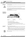
Example 1
[1]
[2]
[3]
[4]
[5]
[6]
[7]
[9]
A
A
51403AXX
Pos. "A" → "Concrete base" section
[1] Hex head screw or stud
[2] Hexagonal nut if [1] is a stud or an upside-down screw
[3] Shims (approx. 3 mm space for shims)
[4] Hexagonal nut
[5] Foundation bracket
[6] Hexagonal nut
[7] Hexagonal nut and foundation screw
[9] Supporting girder
40
Operating Instructions – Explosion-Proof MC.. Series Industrial Gear Units
Mechanical Installation
Gear unit foundation
4
Example 2
[1]
[2]
[3]
[4]
[5]
[6]
[7]
[9]
A
A
51406AXX
Pos. "A" → "Concrete Base" section
[1] Hex head screw or stud
[2] Hexagonal nut if [1] is a stud or an upside-down screw
[3] Shims (approx. 3 mm space for shims)
[4] Hexagonal nut
[5] Foundation bracket
[6] Hexagonal nut
[7] Hexagonal nut and foundation screw
[9] Supporting girder
Operating Instructions – Explosion-Proof MC.. Series Industrial Gear Units
41
Mechanical Installation
Gear unit foundation
4
Example 3
⭌40 mm
[1]
[2]
⭌40 mm
[3]
[4]
[5]
[6]
[7]
[9]
[10]
[10]
A
A
51413AXX
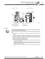
Pos. "A" → "Concrete Base" section
[1] Hex head screw or stud
[2] Hexagonal nut if [1] is a stud or an upside-down screw
[3] Shims (approx. 3 mm space for shims)
[4] Hexagonal nut
[5] Foundation bracket
[6] Hexagonal nut
[7] Hexagonal nut and foundation screw
[9] Supporting girder
[10] Shaft end pump (optional)
Important for MC.PV.. / MC.RV.. industrial gear units:
42
•
The mounting clearance between the bearing cover and gear unit foundation
must be at least 40 mm.
•
The mounting clearance must be dimensioned adequately if the gear unit is
equipped with a shaft end pump [10] (→ "Shaft End Pump" section).
Operating Instructions – Explosion-Proof MC.. Series Industrial Gear Units
Mechanical Installation
Gear unit foundation
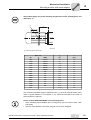
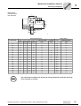
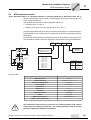
Concrete base
4
The concrete base for the gear unit must be reinforced and connected with the concrete
using steel clamps, steel rods or steel elements. Only the supporting girders are
embedded in the concrete (Pos. "A" → following figure).
A
A
ØTB
ØTM
[1]
[2]
[3]
KG
m
S
U
[4]
[5]
[6]
[7]
P
L
8
[8] Ød
8
B
P
[8]
[9]
s
C
51404AXX
[1] Hex head screw or stud
[2] Hexagonal nut if [1] is a stud or an upside-down screw
[3] Shims (approx. 3 mm space for shims)
[4] Hexagonal nut
[5] Foundation bracket
[6] Hexagonal nut
[7] Hexagonal nut and foundation screw
[8] Welded joint
[9] Supporting girder
Operating Instructions – Explosion-Proof MC.. Series Industrial Gear Units
43
Mechanical Installation
Gear unit foundation
4
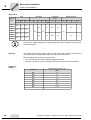
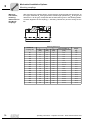
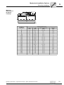
Dimensions
Stud
Gear unit
size
∅TB
Base plate
∅TM
KG
m
P
U
Foundation
screws
A
S
∅d
L
M24
120
Supporting girder
P
B
C
s
[mm]
02
03
04
05
06
07
08
09
M20
24
28
120
M24
28
33
120
120
10
140
12
120
40
150
M36
100
34
3
M30
20
39
30
M30
150
52
The minimum tensile strength of the supporting girders and foundation screws must be
at least 350 N/mm2.
Grouting
The density of the grouting must be equal to that of the base concrete. The grouting is
connected with the concrete base using concrete reinforcement steel.
Before welding the weld seams [9], ensure that
•
the concrete base around the supporting girder has dried,
•
the gear unit with all mount-on components has been aligned to its final position.
Tightening
torques
Screw / nut
44
Tightening torque screw / nut
[Nm]
M8
19
M10
38
M12
67
M16
160
M20
315
M24
540
M30
1,090
M36
1,900
Operating Instructions – Explosion-Proof MC.. Series Industrial Gear Units
Mechanical Installation
Gear unit foundation
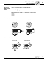
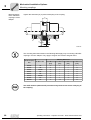
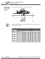
Counterflange for
gear units in
flange-mounted
version
4
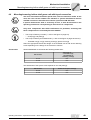
Gear units can be supplied with a mounting flange on the output shaft. These two types
of flange are named according to their bearing assembly:
•
"Mounting flange"
•
"EBD mounting flange."
Both types of flange are suitable for all gear units and mounting positions:
•
MC.L..
•
MC.V..
•
MC.E..
Mounting flange
Solid shaft LSS
Hollow shaft LSS
56611AXX
EBD mounting flange
Solid shaft LSS
Hollow shaft LSS
56609AXX
Operating Instructions – Explosion-Proof MC.. Series Industrial Gear Units
45
4
Mechanical Installation
Gear unit foundation
The counterflange must have the following characteristics:
•
Stiff and torsionally rigid taking into account
–
–
–
–
Gear unit weight
Motor weight
Torque to be transmitted
Additional forces from the customer machine acting on the gear unit (e.g. axial
forces from and towards the gear unit resulting from a mixing process)
•
Horizontal
•
Smooth
•
Vibration isolating, meaning that no vibrations should be transmitted from nearby
machines and components
•
Resonance vibrations may not be created
•
A bore with an H7 fit, corresponding to the dimension drawing for the centering
shoulder of the gear unit flange
The mounting surface of the mounting flange and counterflange must be
absolutely free of grease, oil, and other contaminants (such as small textile
particles, dust, etc.).
The gear drive output shaft must be aligned as accurately as possible in relation to the
counterflange. Alignment affects the lifetime of bearings, shafts, and the coupling.
The incorrect positions permitted for the coupling of the output shaft can be seen either
in section 5.2 or a separate manual on couplings.
Use screws of strength class 8.8 (tensile strength. 640 N/mm2).
Gear unit size
Mounting flange
EBD mounting flange
02
8 x M16
16 x M16
03
8 x M16
16 x M16
04
8 x M16
16 x M16
05
8 x M20
16 x M16
06
8 x M20
16 x M20
07
8 x M20
16 x M20
08
8 x M24
16 x M24
09
8 x M24
16 x M24
MC..
46
Operating Instructions – Explosion-Proof MC.. Series Industrial Gear Units
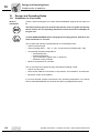
Mechanical Installation
Mounting solid shaft gear units
4.5
4
Mounting solid shaft gear units
Only drive and drive components with ATEX certification are permitted, assuming
that these components are covered by Directive 94/9/EC.
Before mounting the gear unit, check the foundation dimensions with those in the
corresponding gear unit drawings in the "Gear Unit Foundation" section.
Mount the gear unit in the following sequence:
1. Mount the parts according to the gear unit diagrams shown in the "Gear Unit
Foundation" section. The shims [3] facilitate later adjustment and mounting any
replacement gear unit necessary.
2. Secure the gear unit at the selected positions on the supporting girders using three
foundation screws. Position the foundation screws at the maximum distance possible
(two screws on one side of the gear unit and one on the other side). Align the gear
unit as follows:
– Vertically by lifting, lowering or tilting the unit using the nuts of the foundation
screws
– Horizontally by tapping the foundation screws slightly in the required direction
3. After aligning the gear unit, tighten the three nuts of the foundation screws used for
alignment. Carefully insert the fourth foundation screw into the supporting girder and
tighten it securely. When doing so, make sure that the position of the gear unit does
not change. If necessary, align the gear unit again.
4. Tack-weld the ends of the foundation screws to the supporting girders (at least three
welding spots per foundation screw). Tack-weld the foundation screws alternately in
both directions (starting from the center) and symmetrically to the gear unit's center
line. This way, misalignment caused by the welding process is avoided. After all
screws have been tack-welded, they must be permanently welded in the abovementioned order. Adjust the nuts on the foundation screws to ensure that the welded
foundation screws do not cause misalignment of the gear unit housing.
5. After the nuts of the retaining screws of the gear unit have been tack-welded, check
the mounting work again and then cast the enclosure.
6. When the grouting has set, check the mounting one last time and adjust if necessary.
Operating Instructions – Explosion-Proof MC.. Series Industrial Gear Units
47
Mechanical Installation
Mounting solid shaft gear units
4
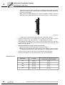
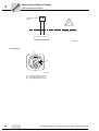
Mounting
accuracy when
aligning
JE
Y
Y
[3]
JE
51590AXX
When aligning the gear unit, make sure that the mounting tolerances for the flatness of
the foundation are not exceeded (ymax values in the following table). If necessary, use
shims [3] to align the gear unit on the foundation plate.
JE
[mm]
ymax
[mm]
< 400
0.035
400 to 799
0.060
800 to 1200
0.090
1200 to 1600
0.125
Flange-mounted
gear units
Before mounting the gear unit, make sure that the requirements described in
section 4.4 "Gear Unit Foundation - Counterflange for Gear Units in FlangeMounted Design" have been fulfilled.
Mount the gear unit in the following sequence:
1. The gear unit must be lowered onto the counterflange with suitable hoisting
equipment. Follow the instructions in section 2.
2. Fasten the gear unit to the counterflange in the correct position with flange bolts.
Tighten them diagonally with full tightening torque (→ section 4.4).
48
Operating Instructions – Explosion-Proof MC.. Series Industrial Gear Units
Mechanical Installation
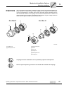
Mounting/removing hollow shaft gears unit with keyed connection
4.6
4
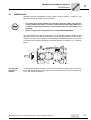
Mounting/removing hollow shaft gears unit with keyed connection
The cover cannot be mounted for special uses, such as continuous shafts. In this
case, the cover can be omitted if the machine or system manufacturer delivers
suitable accessories that offer the enclosure specified in DIN EN 13463.
If special maintenance work is necessary for this, it must be described in the
operating instructions corresponding to the machine or components.
Only drive components with ATEX certification are permitted, assuming that
these components are covered by Directive 94/9/EC.
•
The scope of delivery includes (→ refer to the figure on page 50):
– Circlips [3], end plate [4]
•
The scope of delivery does not include (→ refer to the figure on pages 50 and 51):
– Threaded rod [2], nut [5], retaining screw [6], ejector screw [8]
Select the appropriate thread and length of the threaded rod as well as the retaining
screw depending on the design of the customer's machine.
Thread sizes
SEW-EURODRIVE recommends the following thread sizes:
Gear unit size
Thread size for
• Threaded rod [2]
• Nut (DIN 934) [5]
• Retaining screw [6]
02 - 06
M24
07 - 09
M30
The thread size of the ejector screw depends on the end plate [4]:
Gear unit size
Thread size of ejector screw [8]
02 - 06
M30
07 - 09
M36
Operating Instructions – Explosion-Proof MC.. Series Industrial Gear Units
49
4
Mechanical Installation
Mounting/removing hollow shaft gears unit with keyed connection
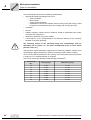
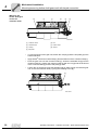
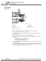
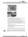
Mounting the
hollow shaft gear
unit to the
customer shaft
[8]
[7]
[1]
[2]
[3]
[4]
[5]
56813AXX
[1] Customer shaft
[5] Nut
[2] Threaded rod
[7] Hollow shaft
[3] Circlips
[8] Socket
[4] End plate
•
To mount and secure the gear unit, attach the circlips [3] and the end plate [4] to the
hollow shaft bore.
•
Apply NOCO® fluid to the hollow shaft [7] and the shaft end of the customer shaft [1].
•
Push the gear unit onto the customer shaft [1]. Screw the threaded rod [2] into the
customer shaft [1]. Tighten the customer shaft [1] with the nut [5] until the shaft end
of the customer shaft [1] and the end plate [4] meet.
•
Loosen the nut [5] and unscrew the threaded rod [2]. After having mounted the gear
unit, secure the customer shaft [1] using the retaining screw [6].
[6]
56814AXX
50
Operating Instructions – Explosion-Proof MC.. Series Industrial Gear Units
Mechanical Installation
Mounting/removing hollow shaft gears unit with keyed connection
Removing the
hollow shaft gear
unit from the
customer shaft
[1]
[6]
[3]
4
[4]
[8]
56815AXX
[1] Customer shaft
[6] Retaining screw
[3] Circlips
[8] Ejector screw
[4] End plate
•
Loosen the retaining screw [6].
•
Remove the outer circlip [3] and the end plate [4].
•
Thread the retaining screw [6] into the customer shaft [1].
•
Turn the end plate [4] and remount the end plate and the outer circlip [3].
•
Screw the ejector screw [8] into the end plate [4] to remove the gear unit from the
customer shaft [1].
Operating Instructions – Explosion-Proof MC.. Series Industrial Gear Units
51
Mechanical Installation
Mounting/removing hollow shaft gear units with shrink disc
4
4.7
Mounting/removing hollow shaft gear units with shrink disc
The cover cannot be mounted for special uses, such as continuous shafts. In this
case, the cover can be omitted if the machine or system manufacturer delivers
suitable accessories that offer the enclosure specified in DIN EN 13463.
If special maintenance work is necessary for this, it must be described in the
operating instructions corresponding to the machine or components.
Only drive components with ATEX certification are permitted, assuming that
these components are covered by Directive 94/9/EC.
Shrink discs serve as a connecting element between the hollow shaft of the gear unit
and the customer shaft. You can find the shrink disc type used (unit designation:
RLK608) in the "Determining the Type of Shrink disc" section.
•
The scope of delivery includes (→ refer to the figure on page 56):
– Circlip [3], end plate [4]
•
The scope of delivery does not include (→ refer to the figure on pages 56 and 58):
– Threaded rod [2], nut [5], retaining screw [6], ejector screw [8]
Select the appropriate thread and length of the threaded rod as well as the retaining
screw depending on the design of the customer's machine.
Thread sizes
SEW-EURODRIVE recommends the following thread sizes:
Gear unit size
02 - 06
07 - 09
Thread size for
•
Threaded rod [2]
•
Nut (DIN 934) [5]
•
Retaining screw [6]
→ see pages 56 and 58
M24
M30
The thread size of the ejector screw depends on the end plate [4]:
52
Gear unit size
Thread size of the ejector screw [8]
02 - 06
M30
07 - 09
M36
Operating Instructions – Explosion-Proof MC.. Series Industrial Gear Units
Mechanical Installation
Mounting/removing hollow shaft gear units with shrink disc
Determining the
type of shrink
disc
4
The shrink disc is usually type RLK608. It is metal colored. "RLK608" is engraved on it.
[11]
[10]
56612AXX
[10] Locking screw
[11] Ejector bores
Depending on the order, other types of shrink disc can be used. Read the separate
operating instructions for the corresponding shrink disc.
Mounting the
shrink disc
•
Do not tighten the locking screws [10] before the customer shaft [1] has been
mounted. This could distort the hollow shaft.
56817AXX
•
Slide the shrink disc [9] with loosened screws onto the hub of the hollow shaft bore.
Position the customer shaft [1] in the hollow shaft bore. Then move the shrink disc
[9] by dimension A (→ following figure, "Dimension A" section) from the shaft end of
the hollow shaft:
Operating Instructions – Explosion-Proof MC.. Series Industrial Gear Units
53
Mechanical Installation
Mounting/removing hollow shaft gear units with shrink disc
4
A
[1]
[10
[9
51986AXX
[1] Customer shaft
[10] Locking screws
[9] Shrink disc
Pay particular attention to the installation of the shrink disc cover.
The clamping area of the shrink disc must be absolutely free of grease.
Dimension A
Gear unit size
54
MC..
Shrink disc type RLK608
Dimension A [mm]
02
39
03
45
04
44
05
42
06
44
07
50
08
51
09
49
Operating Instructions – Explosion-Proof MC.. Series Industrial Gear Units
Mechanical Installation
Mounting/removing hollow shaft gear units with shrink disc
Mounting the
hollow shaft gear
unit to the
customer shaft
•
4
Before mounting the gear unit, degrease the hollow shaft bore and the customer
shaft [1].
[1]
[1]
[7]
[7]
56820AXX
•
Apply a bit of NOCO® fluid to the machine shaft in the area of the bushing [11].
[11]
[7]
[1]
56811AXX
Never apply NOCO® fluid directly to the bushing since the paste may get into the
clamping area of the shrink disc when the input shaft is connected.
Operating Instructions – Explosion-Proof MC.. Series Industrial Gear Units
55
4
Mechanical Installation
Mounting/removing hollow shaft gear units with shrink disc
[11]
[7]
[1]
[2] [9] [10] [3]
[4]
[5]
56816AXX
[1] Customer shaft
[7] Hollow shaft
[2] Threaded rod
[9] Shrink disc
[3] Circlip
[10] Locking screws
[4] End plate
[11] Socket
[5] Nut
•
To mount and secure the gear unit, attach the circlips [3] and the end plate [4] to the
hollow shaft bore.
•
Push the gear unit onto the customer shaft [1]. Screw the threaded rod [2] into the
customer shaft [1]. Tighten the customer shaft [1] with the nut [5] until the shaft end
of the customer shaft [1] and the end plate [4] meet.
•
Loosen the nut [5] and unscrew the threaded rod [2]. After mounting the gear unit,
secure the customer shaft [1] using the retaining screw [6].
[10]
[6]
56817AXX
56
Operating Instructions – Explosion-Proof MC.. Series Industrial Gear Units
Mechanical Installation
Mounting/removing hollow shaft gear units with shrink disc
Tightening the
type RLK608
shrink disc
4
Tighten the retaining screws by hand while the shrink disc is being aligned. Tighten the
retaining screws one after the other in clockwise direction (not diagonally), each with a
quarter turn.
56812AXX
The screws of shrink discs with slotted taper bushings must be screwed on beginning
with the screw on one side of the slot and continuing with the screw on the other side of
the slot.
Tighten the screws by a quarter turn in several steps until the screwing surfaces of the
outer and inner rings are aligned.
Mounting is determined by the axial movement of the taper bushings and can be done
without a torque wrench.
[L2]
[L1]
S=0
S>0
[9a]
[9b]
[7]
[1]
[10]
56886AXX
[L1] Condition at the time of shipment (preassembled)
[7] Hollow shaft
[L2] Ready for operation (final assembly)
[1] Customer shaft
[9a] Bevel
[10] Locking screws
[9b] Taper bushing
Operating Instructions – Explosion-Proof MC.. Series Industrial Gear Units
57
Mechanical Installation
Mounting/removing hollow shaft gear units with shrink disc
4
Removing the
shrink disc
Loosen the locking screws [10] by a quarter turn one after the other to avoid straining
the connecting surface.
Never completely remove the locking screws since this could cause an accident.
If the taper bushing and the tapered ring do not loosen by themselves:
Take the necessary number of locking screws and screw them into the removal bores
evenly. Tighten the locking screws in several steps until the tapered bushing separates
from the tapered ring.
Remove the shrink disc from the hollow shaft.
Removing the
hollow shaft gear
unit from the
customer shaft
[1]
[6]
[3]
[4]
[8]
56818AXX
Cleaning and
lubrication
[1] Customer shaft
[4] End plate
[3] Circlip
[6] Retaining bolt
[8] Ejector screw
•
Loosen the retaining screw [6].
•
Remove the outer circlip [3] and the end plate [4].
•
Thread the retaining screw [6] into the customer shaft [1].
•
Turn the end plate [4] and remount the end plate and the outer circlip [3].
•
Screw the ejector screw [8] into the end plate [4] to remove the gear unit from the
customer shaft [1].
Clean the shrink disc after removal and
•
lubricate locking screw [10] on the threading and under the head with an MoS2
compound, "gleitmo 100" from FUCHS LUBRITECH (www.fuchs.-lubritech.de) for
example.
•
Lubricate the tapered surfaces and the screwing surfaces of the tapered bushing with
a thin layer (0.01 - 0.02 mm) using "gleitmo 900" lubricant from FUCHS LUBRITECH
(www.fuchs.-lubritech.de) or a comparable product from another manufacturer.
Spray on the lubricant until the layer is thick enough to cover the surface (in this case,
approx. 0.02 mm thick).
58
Operating Instructions – Explosion-Proof MC.. Series Industrial Gear Units
Mechanical Installation
Mounting a motor with motor adapter
4.8
4
Mounting a motor with motor adapter
Motor adapters [1] are available for connecting IEC motors of sizes 132 to 315 to MC
series industrial gear units.
[1]
[2]
51594AXX
[1] Motor adapter
[2] Coupling
[1]
[2]
51593AXX
[1] Motor adapter
[2] Coupling
For installing couplings [2], refer to the notes in the "Mounting couplings"
section.
Operating Instructions – Explosion-Proof MC.. Series Industrial Gear Units
59
4
Mechanical Installation
Mounting a motor with motor adapter
When selecting a motor, take the permitted motor weight, the gear unit mounting
position, and the type of gear unit mounting into account according to the following
tables.
The following applies to all tables:
GM = Motor weight
GG = Gear unit weight
Industrial Gear Unit Series
Type of Mounting
MC.RL..
MC.PL..
Foot mounting
GM ≤ G G
G M ≤ GG
Shaft mounted
design
GM ≤ 0.5GG
GM ≤ G G
Flange mounting
GM ≤ 0.5GG
GM ≤ G G
Industrial Gear Unit Series
Type of Mounting
MC.RV..
MC.PV..
Foot mounting
GM ≤ 1.5GG
GM ≤ G G
Shaft mounted
design
GM ≤ G G
GM ≤ G G
Flange mounting
GM ≤ G G
GM ≤ 0.75GG
Industrial Gear Unit Series
Type of Mounting
MC.PE..
MC.RE..
Foot mounting
GM GG
GM 1.5GG
Shaft mounted
design
GM GG
GM G G
Flange mounting
GM GG
GM G G
These tables are for stationary operation only. Contact SEW-EURODRIVE if the
gear unit moves while in operation (e.g. travel drive).
60
Operating Instructions – Explosion-Proof MC.. Series Industrial Gear Units
Mechanical Installation
Mounting a motor with motor adapter
4
These tables apply only to the following assignment of motor size/weight Fq and
dimension "x."
[1]
X
Fq
56753AXX
[1] Center of gravity of the motor
Motor size
Fq
x
IEC
NEMA
[N]
[mm]
132S
213/215
579
189
132M
213/215
677
208
160M
254/286
1.059
235
160L
254/286
1.275
281
180M
254/286
1.619
305
180L
254/286
1.766
305
200L
324
2.354
333
225S
365
2.943
348
225M
365
3.237
348
250M
405
4.267
395
280S
444
5.984
433
280M
445
6.475
433
315S
505
8.142
485
315M
505
315L
8.927
485
11.772
555
The maximum permitted weight of attached motor Fq has to be reduced linearly if the
center of gravity distance x is increased. Fq max cannot be increased if the center of
gravity distance is reduced.
Please contact SEW-EURODRIVE in the following cases.
•
When retrofitting motor adapters with a cooling air fan (not for motors of sizes 132S
and 132M).
•
After the motor adapter is removed, the gear unit must be re-aligned.
Operating Instructions – Explosion-Proof MC.. Series Industrial Gear Units
61
Mechanical Installation
Installing industrial gear units in potentially explosive areas
4
4.9
Installing industrial gear units in potentially explosive areas
Observe the safety notes listed in section 2 when installing a gear unit in a
potentially explosive area.
4.10 Gear units in category II2GD
•
Ambient
temperature
Explosion-proof MC.. series gear units comply with the design requirements
for group II, categories 2G or 3G (potentially explosive gas atmosphere) and
2D or 3D (potentially explosive dust atmosphere). These gear units are intended for use in zones 1 and 21 or zones 2 and 22.
Gear units in category II2GD or II3GD may be operated at ambient temperatures from
-20 °C to +40 °C only.
Any ambient temperatures deviating from this range have to be listed on the
nameplate.
62
Temperature
class
Mains-operated gear units in categories II2G and II3G (potentially explosive gas
atmosphere) are approved for temperature classes T3 to T6 depending on their speed,
reduction ratio, and mounting position. The category and temperature class of the gear
unit are on the nameplate.
Surface
temperature
The maximum surface temperature of gear units in categories II2D and II3D is either
120 °C or 140 °C, depending on their speed, reduction ratio, and mounting position.
Lower surface temperatures are only permitted after consultation with SEWEURODRIVE. The category and maximum surface temperature must be on the nameplate. The system operator must ensure that dust accumulation does not exceed an
upper limit of 5 mm in accordance with EN50281-1-2.
Degree of
protection
The degree of protection is specified on the nameplate as an IP number.
Environmental
conditions
Take measures to ensure that the gear units are sufficiently ventilated and that they are
not heated by an external heat source (e.g. the coupling).
Output power and
output torque
Output torque, speeds, and permitted radial and axial forces must be in accordance with
the specifications on the nameplate.
Operating Instructions – Explosion-Proof MC.. Series Industrial Gear Units
Mechanical Installation Options
Important installation instructions
5
Mechanical Installation Options
5.1
Important installation instructions
5
Before starting work on couplings, disconnect the motor from its supply and
prevent it from being switched on again.
Do not use spacers to make installation easier.
Important
installation
instructions
•
Use a mounting device only for installing input and output elements. Use the center
bore and the thread on the shaft end for positioning.
•
Never drive couplings, pinions, etc. onto the shaft end by hitting them with a
hammer (damage to bearings, housing and the shaft).
•
In the case of belt pulleys, make sure the belt has the correct tension (in
accordance with the manufacturer's instructions).
•
Use belts with sufficient electrical shunt resistance < 109 Ω.
•
The requirements of IEC 60695-11-10, category FV-0 must be met.
•
Power transmission elements should be balanced after fitting and may not give rise
to radial or axial forces that are not permitted.
Note:
Mounting is easier if you first apply lubricant to the output element or heat it up briefly
(to 80 - 100 °C).
Adjust the following when mounting couplings:
a) Axial misalignment (maximum and minimum distances)
b) Offset (concentricity error)
c) Angular offset
a)
b)
c)
03356AXX
Input and output elements such as couplings must be covered with a touch guard.
Operating Instructions – Explosion-Proof MC.. Series Industrial Gear Units
63
Mechanical Installation Options
Important installation instructions
5
The following methods for measuring angular offset and axial misalignment are
important for complying with the mounting tolerances specified in the "Mounting
Couplings" section.
Measuring
angular offset
with a feeler
gauge
The following figure shows the measurement of angular offset (α) using a feeler gauge.
This method only achieves an accurate result when the deviation of the coupling faces
is eliminated by turning both coupling halves by 180 and then calculating the average
value from the difference (a1– a2).
a1
a
D
α
a2
52063AXX
Measuring
angular offset
using a micrometer dial
The following figure shows measurement for angular offset using a micrometer dial. This
measuring method yields the same result as described in the "Measuring Angular Offset
with a Feeler Gauge" section if the coupling halves are rotated together (e.g. with a
coupling pin), so that the needle of the micrometer dial does not perceptibly move on the
measuring surface.
a1
a
D
α
f2
f1
a2
52064AXX
A prerequisite for this measuring method is that no axial play is in the shaft bearings
when the shafts rotate. If this condition is not fulfilled, the axial play between the faces
of the coupling halves must be eliminated. As an alternative, you can use two micrometer dials positioned on the opposite sides of the coupling (to calculate the difference
of the two micrometer dials when rotating the coupling).
64
Operating Instructions – Explosion-Proof MC.. Series Industrial Gear Units
Mechanical Installation Options
Important installation instructions
Measuring offset
using a straight
edge and a
micrometer dial
5
The following figure shows the measurement for offset using a straight edge. Permissible values for offset are usually so small that the best measurement results can be
achieved with a micrometer dial. If you rotate one coupling half together with the
micrometer dial and divide the deviation by two, the deviation displayed on the micrometer dial indicates the misalignment (dimension "b") that includes the offset of the other
coupling half.
b
f2
f1
52065AXX
Measuring offset
using a micrometer dial
The following figure shows the how to measure using a more accurate measuring
method. The coupling halves are rotated together without letting the needle of the
micrometer dial slide onto the measuring surface. Offset is obtained by dividing the
deviation displayed on the micrometer dial (dimension "b").
b
f2
f1
52066AXX
Operating Instructions – Explosion-Proof MC.. Series Industrial Gear Units
65
Mechanical Installation Options
Mounting couplings
5
5.2
Mounting couplings
ROTEX Coupling
[1]
[2]
[1]
51663AXX
[1] Coupling hub
[2] Annular gear
The low-maintenance, elastic ROTEX coupling is capable of compensating for radial
and angular offsets. Careful and exact alignment of the shaft ensures a long service life
for the coupling.
Couplings must be identified for use in potentially explosive atmospheres.
Note the special operating instruction for ROTEX couplings.
66
Operating Instructions – Explosion-Proof MC.. Series Industrial Gear Units
Mechanical Installation Options
Mounting couplings
Mounting the
coupling halves
onto the shaft
5
L1
ØdH
ØdW
G
s
s
E
51689AXX
Mounting Dimensions
Locking Screw
Coupling Size
E
[mm]
s
[mm]
14
13
1.5
10
19
16
2
18
24
18
2
27
28
20
2.5
30
38
24
3
42
26
3
48
28
3.5
51
40
50
76
M8
20
55
30
4
60
48
56
86
M10
40
65
35
4.5
68
55
63
91
M10
40
75
40
5
80
65
72
104
M10
40
dH
[mm]
dW
[mm]
L1 (Alu / GC / GCI)
[mm]
L1 (steel)
[mm]
G
Tightening torque
[Nm]
7
-
-
M4
2.4
12
26
-
M5
4.8
20
30
-
M5
4.8
22
34
-
M6
8.3
38
28
40
60
M8
20
46
36
46
70
M8
20
90
45
5.5
100
80
83
121
M12
69
100
50
6
113
95
92
-
M12
69
110
55
6.5
127
100
103
-
M16
195
125
60
7
147
120
116
-
M16
195
140
65
7.5
165
135
127
-
M20
201
160
75
9
190
160
145
-
M20
201
180
85
10.5
220
185
163
-
M20
201
The shaft distance (dimension E) must be strictly observed so that the axial play
of the coupling is ensured.
Operating Instructions – Explosion-Proof MC.. Series Industrial Gear Units
67
Mechanical Installation Options
Mounting couplings
5
Mounting dimensions of ROTEX
coupling in motor
adapter
Tighten the setscrews (A) to prevent axial play of the coupling.
E
A
A
L1
L2
L3
51696AXX
The mounting dimensions listed in the following table apply only to mounting a ROTEX
coupling in a motor adapter. They apply to all gear unit versions and gear ratios.
Mounting Dimensions
ROTEX Coupling
Size
IEC Motor Size
E
[mm]
L1
[mm]
L2
[mm]
L3
[mm]
R28/38
132
20
0
–17
3
R38/45
160
24
1
0
25
R42/55
180/200
26
–1
0
25
R48/60
225
28
0
–3
25
R55/70
225
30
0
–5
25
R65/75
250/280
35
0
–10
25
R75/90
315
40
0
–15
25
R90/100
315
45
–20
0
25
The shaft distance (dimension E) must be strictly observed to ensure axial play of
the coupling.
68
Operating Instructions – Explosion-Proof MC.. Series Industrial Gear Units
Mechanical Installation Options
Mounting couplings
Nor-Mex coupling
for types G and E
5
The low-maintenance Nor-Mex couplings for types G and E are torsionally flexible couplings capable of compensating for axial misalignment and angular and radial offset.
Torque is transmitted via an elastic spacer bush with high damping properties that is
also oil and heat resistant. The couplings can be used for either direction of rotation and
can be mounted in any position. The design of the Nor-Mex G type coupling allows the
elastic element [5] to be replaced without shaft offset.
Nor-Mex E
Nor-Mex G
[1]
[2]
[6]
[1]
[5]
[4]
[3]
[1]
[2]
51667AXX
[1] Coupling hub
[1] Socket head screw
[2] Elastic spacer bush
[2] Washer
[3] Claw ring
[4] Flange hub
[5] Elastic spacer bush
[6] Coupling hub
Couplings must be identified for use in potentially explosive atmospheres.
Note the special operating instruction for Nor-Mex E or Nor-Mex G couplings.
Operating Instructions – Explosion-Proof MC.. Series Industrial Gear Units
69
Mechanical Installation Options
Mounting couplings
5
Mounting
instructions,
mounting
dimensions for
Nor-Mex G
couplings
After mounting the coupling halves, ensure that the recommended play (dimension S2
for G type, dimension S1 for E type) and the overall length (dimension LG for G type and
dimension LE for E type) correspond with the dimensions given in the following tables.
Accurate alignment of the coupling (→ "Mounting Tolerances") ensures a long service
life.
IE
IG
S2
LG
51674AXX
Nor-Mex G
Coupling Size
82
70
Mounting Dimensions
lE
[mm]
lG
[mm]
LG
[mm]
Perm. deviation S2
[mm]
Weight
[kg]
40
40
92
12±1
1.85
97
50
49
113
14±1
3.8
112
60
58
133
15±1
5
128
70
68
154
16±1
7.9
148
80
78
176
18±1
12.3
168
90
87
198
21±1.5
18.3
194
100
97
221
24±1.5
26.7
214
110
107
243
26±2
35.5
240
120
117
267
30±2
45.6
265
140
137
310
33±2.5
65.7
295
150
147
334
37±2.5
83.9
330
160
156
356
40±2.5
125.5
370
180
176
399
43±2.5
177.2
415
200
196
441
45±2.5
249.2
480
220
220
485
45±2.5
352.9
575
240
240
525
45±2.5
517.2
Operating Instructions – Explosion-Proof MC.. Series Industrial Gear Units
Mechanical Installation Options
Mounting couplings
5
Mounting
dimensions of
Nor-Mex E
couplings
IE
IG
S2
LG
51674AXX
Nor-Mex E
Coupling Size
Mounting Dimensions
lE
[mm]
LE
[mm]
Perm. deviation S1
[mm]
Weight
[kg]
67
30
62.5
2.5± 0.5
0.93
82
40
83
3± 1
1.76
97
50
103
3± 1
3.46
112
60
123.5
3.5± 1
5
128
70
143.5
3.5± 1
7.9
148
80
163.5
3.5± 1.5
12.3
168
90
183.5
3.5± 1.5
18.4
194
100
203.5
3.5± 1.5
26.3
214
110
224
4± 2
35.7
240
120
244
4± 2
46.7
265
140
285.5
5.5± 2.5
66.3
295
150
308
8± 2.5
84.8
330
160
328
8± 2.5
121.3
370
180
368
8± 2.5
169.5
415
200
408
8± 2.5
237
480
220
448
8± 2.5
320
575
240
488
8± 2.5
457
Operating Instructions – Explosion-Proof MC.. Series Industrial Gear Units
71
5
Mechanical Installation Options
Mounting couplings
Mounting dimensions of the NorMex G coupling
in the motor
adapter
Tighten the setscrews (A) to prevent axial play of the coupling.
S2
A
A
L2
L1
L3
51672AXX
The mounting dimensions listed in the following table apply only to mounting a Nor-Mex
coupling in a motor adapter.
NOR-MEX G.. Coupling Size
IEC Motor Size
Gear unit size
Gear ratio i
72
97
97
112
128
148
168
194
214
132
160
160/180
200
225
250/280
280/315
315
Mounting
dimensions
[mm]
All
All
S2
14
14
15
16
18
21
24
26
L3
3
25
25
25
25
25
25
25
MC3R02
i = 14 to 63
L2
-
5
5
5
10
2
1
0
L1
-
6
5
4
–3
2
0
–1
MC3R05
i = 14 to 63
L2
-
5
5
5
4
2
5
0
L1
-
6
5
4
3
2
–4
–1
MC3R08
i = 14 to 63
L2
-
5
5
5
4
2
1
5
L1
-
6
5
4
3
2
1
–6
Other MC..
I = 7.1 to 112
L2
–5
5
5
5
4
2
1
0
L1
–6
6
5
4
3
2
0
–1
Operating Instructions – Explosion-Proof MC.. Series Industrial Gear Units
Mechanical Installation Options
FXM Backstop
5.3
5
FXM Backstop
Backstops prevent undesirable reverse rotation. During operation, rotation in one
specified direction of rotation only is permitted.
•
The motor may not be started in the blocking direction. Make sure that the
current supply to the motor is correct in order to achieve the required direction
of rotation. Operating the motor in the blocking direction could destroy the
backstop.
•
Before changing the blocking direction, contact SEW-EURODRIVE.
The maintenance-free FXM type backstop is a centrifugally operated backstop with
sprags that lift off. Once the lift-off speed is reached, the sprags lift off from the contact
surface of the outer ring completely. The backstop is lubricated with gear oil. An arrow
on the gear unit housing indicates the permitted direction of rotation [1] (→ following
figure).
[1]
[1]
51639AXX
Changing the
direction of
rotation
To change the direction of rotation, turn the inner ring with the sprags 180°. Pull out the
inner ring with the sprags using a pulling device (not included in the scope of delivery),
turn it 180° and then replace it.
Operating Instructions – Explosion-Proof MC.. Series Industrial Gear Units
73
5
Mechanical Installation Options
FXM Backstop
...for a backstop
mounted outside
the gear unit
[7]
[1]
[4]
[5]
[2]
[3]
59210AXX
[1] Outer ring
[5] Backstop cover
[2] Retaining screws
[6] Centering disk
[3] Circlip
[7] Gear unit bearing cover
[4] Inner ring with cage and sprags
1. Drain the oil from the gear unit (→ "Inspection and Maintenance" section).
2. Loosen the retaining screws [2] of the backstop.
3. Remove the outer ring [1]. To facilitate removal, slightly turn the outer ring [1] in freewheeling direction.
4. Remove the circlip [3], and inner ring with cage and sprags [4].
5. Turn the inner ring [4] with the sprags 180° and clean all of the contact surfaces
between the
– gear unit cover [7] and centering disk [6]
– centering disk [6] and outer ring [1]
– outer ring [1] and backstop cover [5]
and renew the sealing in the contact surfaces using a suitable sealing compound
before re-mounting.
6. Install the parts again in reverse order. The force applied during installation should
be channeled to the inner ring [4] and not to the cage with the wedge elements. Use
the threaded holes on the inner ring [4] for mounting.
74
Operating Instructions – Explosion-Proof MC.. Series Industrial Gear Units
Mechanical Installation Options
FXM Backstop
5
7. Secure the inner ring [4] with the circlip [3] in the axial direction. Mount the outer ring
[1] using the retaining screws [2]. Observe the tightening torques specified in the
following table:
Screw Size
Tightening Torque [Nm]
M5
6
M6
10
M8
25
M10
48
M12
84
M16
206
M20
402
M24
696
M30
1420
8. Change the direction arrow on the gear unit housing.
9. Refill the gear unit with oil (→ section 10). Check the oil level.
10.After mounting, check whether the backstop is running smoothly.
Operating Instructions – Explosion-Proof MC.. Series Industrial Gear Units
75
5
Mechanical Installation Options
FXM Backstop
... with the backstop installed in
the gear unit
[4]
[1]
[2]
[7] [6
[5]
[3]
[8]
51645AXX
[1] Outer ring
[6] Bearing cover
[2] Circlip
[7] Shims
[3] Inner ring with cage and wedge elements
[8] Pulling device
[4] Supporting ring
[9] Gear unit housing
[5] Sleeve
1. Drain the oil from the gear unit (→ "Inspection and Maintenance" section).
2. Remove the bearing cover [6], shims [7] and sleeve [5]. Make sure that you do not
confuse the shims [7] and sleeve [5] with the bearing cover [6] and outer ring [1].
They must be re-installed in the correct order.
3. Remove the circlip [2] from the input shaft.
4. Remove the inner ring with the cage and wedge elements [3] using a suitable pulling
device [8]. Use the threaded holes on the inner ring [3] for mounting.
5. Turn the inner ring [3] with the wedge elements 180° and clean all of the contact surfaces between the bearing cover [6] and the gear unit housing [9].
6. Install the parts again in reverse order. Use a suitable sealing compound to seal the
contact surfaces between the bearing cover [6] and the gear unit housing [9]. The
force applied during installation should be channeled to the inner ring [3] and not to
the cage with the wedge elements.
7. When mounting the backstop, turn it in the freewheeling direction so that the clamping elements move into the outer ring.
8. Secure the inner ring [3] with the circlip [2] in the axial direction.
9. Mount sleeve [5], shims [7] and bearing cover [6] in reverse order.
10.Change the direction arrow on the gear unit housing.
11.Refill the gear unit with oil (→ "Lubricants" section). Check the oil level.
12.After mounting, check whether the backstop is running smoothly.
76
Operating Instructions – Explosion-Proof MC.. Series Industrial Gear Units
Mechanical Installation Options
SHP shaft end pump
5.4
5
SHP shaft end pump
Use
The maintenance-free SHP shaft end pump is the preferred solution for gear unit sizes
04 to 09 for pressure lubrication (→ section 10 "Design and Operating Notes").
The maintenance-free SHP.. shaft end pump can be used to lubricate gear unit parts of
size 04 to 09 gear units that are not submerged in the oil bath. The shaft end pump can
be operated in both directions of rotation.
A minimum input speed is required for the shaft end pump to function properly. If
you use variable input speeds (e.g. inverter-controlled drives) or want to change
the speed range of a gear unit with a shaft end pump that has already been delivered, it is essential that you contact SEW-EURODRIVE.
Pump position
The pump is mounted on the gear unit externally and is driven directly by the input shaft
or the intermediate shaft of the gear unit. This ensures that the pump functions reliably.
The pump position depends on the following factors:
•
Number of gear stages
•
Type of gear unit (helical or helical-bevel gear unit)
•
Shaft position of the gear unit
•
Type of output shaft
Check that the shaft end pump does not collide with other structures.
The following tables display the positions of the pumps:
Operating Instructions – Explosion-Proof MC.. Series Industrial Gear Units
77
Mechanical Installation Options
SHP shaft end pump
5
Shaft Positions
23
131)
241)
14
031)
041)
MC2P
• Solid shaft
• Hollow shaft with
keyway
• Hollow shaft with
shrink disc
MC3P
• Solid shaft
• Hollow shaft with
keyway
• Hollow shaft with
shrink disc
1) The maximum permitted external forces on the output shaft are lower.
Shaft Positions
03
04
MC2R
• Solid shaft
MC2R
• Hollow shaft with
keyway
MC2R
• Hollow shaft with
shrink disc
MC3R
• Solid shaft
• Hollow shaft with
keyway
• Hollow shaft with
shrink disc
1) The maximum permitted external forces on the output shaft are lower.
78
Operating Instructions – Explosion-Proof MC.. Series Industrial Gear Units
Mechanical Installation Options
SHP shaft end pump
5
Pump suction
•
Note that the gear unit must be sufficiently lubricated from the very beginning.
•
Do not change the diameter of the tube / pipe connection.
•
Do not open the pressure line [PRE].
•
If the shaft end pump does not build up pressure within 10 seconds after the
gear unit has been started, contact SEW-EURODRIVE.
Shaft end pump
mounted on top
of the MC.V.. gear
unit
Dry starting can occur when the shaft pump end is mounted on top of the gear
unit.
[1]
[1]
[2]
57683AXX
[1] Separate oil filling plug on the intake pipe
[2] Oil flow monitor or optical oil flow indicator (not visible in the figure)
It is essential for the oil pump to begin pumping as soon as the main motor begins to
turn. If it does not, open the separate oil filling plug [1] and add some oil (1 - 4 liters).
Close the separate oil filling plug as soon as the oil starts circulating (check using the oil
flow monitor or optical oil flow indicator [2]).
This procedure is especially important if the gear unit has not been used for a long time
and there is air in the suction line and oil pump.
Operating Instructions – Explosion-Proof MC.. Series Industrial Gear Units
79
Mechanical Installation Options
Installation with steel frame
5
5.5
Installation with steel frame
For MC.. series industrial gear units in the horizontal mounting position (MC2PL..,
MC3PL.., MC2RL.., and MC3RL..), SEW-EURODRIVE supplies preassembled drive
packages on a steel frame (swing base or base plate).
Swing base
A swing base is a steel frame [1] that accommodates the gear unit, (hydro) coupling, and
motor (and brake, if required). This normally refers to
•
Hollow shaft gear unit or
•
Solid shaft gear unit with a fixed flange coupling on the output shaft
The steel construction [1] is supported by a torque arm [2] (→ section 5.6 "Torque Arm").
[1]
[2]
51691AXX
[1] Swing base
[2] Torque arm
Make sure that the
•
System is dimensioned to enable the torque of the torque arm to be absorbed
(→ "Gear Unit Foundation" section 4.4).
•
Swing base is not distorted during installation (possible damage to gear unit
and coupling)
If the gear unit moves to the side during operation or there is a noticeably large
number of peak torques, you should not use a fixed torque arm. Use a torque arm
with flexible bearing bushing instead. Contact SEW-EURODRIVE.
80
Operating Instructions – Explosion-Proof MC.. Series Industrial Gear Units
Mechanical Installation Options
Torque arm
Base plate
5
A base frame is a steel frame [1] that accommodates the gear unit, (hydro) coupling, and
motor (and brake, if required). The steel frame is supported by several foot mountings
[2]. This frame is usually used for solid shaft gear units with elastic coupling on the
output shaft.
[1]
[2]
51692AXX
[1] Base plate
[2] Foot mounting
Make sure that the
•
support structure of the foot mounting is adequately dimensioned (→ "Gear
Unit Foundation" section 4.4).
•
base plate is not distorted due to incorrect alignment (possible damage to gear
unit and coupling).
Observe the special installation instructions for the swing base or the base plate.
5.6
Torque arm
If the gear unit moves to the side during operation or there is a noticeably large
number of peak torques, you should not use the fixed torque arm. Use a torque
arm with flexible bearing bushing instead. Please contact SEW-EURODRIVE.
Mounting options
An optional torque arm to be mounted directly to the gear unit or to the swing base can
be supplied.
Operating Instructions – Explosion-Proof MC.. Series Industrial Gear Units
81
5
Mechanical Installation Options
Torque arm
Mounted directly
to the gear unit
Always mount the torque arm on the side of the driven machine.
51703AXX
The torque arm can be directly mounted to the gear unit in the case of tensile load and
thrust load. Additional tensile or thrust load may be caused by:
•
Deviations in concentricity during operation
•
Thermal expansion of the driven machine
To avoid such strain, the anchor bolt [5418] is equipped with double connection
elements that allow sufficient lateral and radial play [1].
0°
±1°
90
°
+5
-5 °
°
1°
[1]
[5418]
[5416]
[5416]
51705AXX
It is essential to have sufficient play [1] between the torque arm and retaining
plate [5416] as well as between the torque arm and gear unit. This way, no bending
force can act on the torque arm and the bearings of the output shaft are not
subjected to any additional load.
82
Operating Instructions – Explosion-Proof MC.. Series Industrial Gear Units
Mechanical Installation Options
Torque arm
Foundation for
torque arm
5
To build the foundation for the directly mounted torque arm or the torque arm mounted
to the swing base of the motor, proceed as follows:
•
Place the supporting girders horizontally in their previously measured locations.
Anchor the supporting girders in the concrete base [A].
•
Reinforce the concrete base [A] and connect it to the base using steel rods. The
concrete base [A] must withstand at least the same load as the weld joints of the
foundation screws.
•
After having mounted the torque arm, position the grouting [B] and bond it to the
concrete base [A] with steel rods.
HA
[5412]
[5422]
[5410]
[5420]
[5414]
[5424]
[5418]
[5416]
ØMT
B
A
JS
JT
51694AXX
[A] Concrete base
[5416] Anchor plate
[B] Grouting
[5418] Anchoring bolt
[5410] Anchoring
[5420] Hexagonal nut
[5412] Anchoring bolt
[5422] Retaining ring
[5414] Eye bolt
[5424] Retaining ring
All parts listed except items A and B are included in the scope of delivery.
Length HA of the torque arm (→ table below) can be selected as required within the
range from HAmin to HAmax. If you require an HA that is longer than HAmax, the torque
arm will be supplied as a special version.
Gear unit size
HA
[mm]
JT
[mm]
JS
[mm]
∅MT
[mm]
148
100
18
188
130
22
min. ... max.
02, 03
360 to 410
04, 05
405 to 455
06, 07
417 to 467
08, 09
432 to 482
Operating Instructions – Explosion-Proof MC.. Series Industrial Gear Units
83
Mechanical Installation Options
Mounting a V-belt drive
5
5.7
Mounting a V-belt drive
The V-belt drive is used when the overall gear ratio needs to be adjusted. The standard
scope of delivery includes the motor bracket, belt pulleys, V-belt, and belt guard.
Only use belts with sufficient electrical shunt resistance (< 109 Ω).
•
Only when the protective cover was not supplied by SEW-EURODRIVE: Before
a protective cover can be installed, a risk analysis must prove that no sources
of ignition (e.g. impact sparks from grinding) can occur. This risk analysis
must be made by the manufacturer.
Note the permitted motor weight listed in the following table:
GM = Motor weight
GG = Gear unit weight
MC2P/MC3P
MC2R/MC3R
Contact SEW-EURODRIVE
Contact SEW-EURODRIVE
Upright mounting:
Foot mounted design GM ≤ 0,4 × GG
Shaft mounted design GM ≤ 0,4 × GG
Flange mounted design GM ≤ 0,4 × GG
Horizontal output shaft:
Foot mounted design GM ≤ 1,0 × GG
Shaft mounted design GM ≤ 1,0 × GG
Flange mounted design GM ≤ GG
54046AXX
54047AXX
Vertical output shaft:
Foot mounted design GM ≤ 0,4 × GG
Contact SEW-EURODRIVE
Shaft mounted design GM ≤ 0,4 × GG
Flange mounted design GM ≤ 0,4 × GG
54052AXX
Heavier motor weights are only permitted if they have been specified in the purchase
order.
84
Operating Instructions – Explosion-Proof MC.. Series Industrial Gear Units
Mechanical Installation Options
Mounting a V-belt drive
GM = Motor weight
5
GG = Gear unit weight
[5214]
d1
[5260]
[5210]
[5110]
[5218]
[5112]
[5262]
[5114]
[5212]
[5216]
51695AXX
[5110, 5112] Motor bracket
[5214, 5216] Belt pulleys
[5114] Mounting bracket
[5218] V-belt
[5210, 5212] Taper bushing
[5260] Belt guard cover
Assembly
The following installation instructions are only valid when you use taper bushings
and belts supplied by SEW-EURODRIVE.
If you use parts from other manufacturers, observe the corresponding information.
•
Mount the motor on the motor bracket (retaining screws not included in the scope of
delivery).
•
Attach the back plate of the belt guard cover [5260] to the motor bracket [5112, 5114]
of the gear unit using screws. Observe the required direction of the opening of the
belt guard cover [5260]. To adjust the tension of the V-belt, loosen the upper screw
[5262] of the backplate of the belt guard cover.
•
Installing the taper bushings [5210, 5212]:
– Mount the belt pulleys [5214, 5216] onto the motor and gear shaft as close to the
shaft shoulder as possible.
– Degrease the taper bushings [5210, 5212] and belt pulleys [5214, 5216]. Insert
the taper bushings [5210, 5212] into the belt pulleys [5214, 5216]. Make sure that
the bores are aligned accurately.
– Grease the retaining screws and screw them into the threading of the belt pulley
hub.
Operating Instructions – Explosion-Proof MC.. Series Industrial Gear Units
85
5
Mechanical Installation Options
Mounting a V-belt drive
– Clean motor and gear shaft and attach the completed belt pulleys [5214, 5216].
– Tighten the screws. Tap the sleeve lightly and retighten the screws. Repeat this
procedure several times.
– Make sure that the belt pulleys [5214, 5216] are aligned accurately. Check the
alignment using a steel ruler that has contact at four points (→ following figure).
51697AXX
– Fill the clamping holes with grease to prevent the penetration of dirt.
•
Pull the V-belts [5218] over the pulleys [5214, 5216] and tighten them using the
adjustment screws in the motor bracket (→ "V-Belt Tightening" section).
•
The maximum permissible error is 1 mm per 1,000 mm span of the V-belt. This way,
maximum power transmission is ensured and excessive load on the gear and motor
shafts can be prevented.
•
Check the belt tension using a V-belt tension meter:
– Measure the length of the V-belt span (= free V-belt length)
– Measure the perpendicular force that causes a 16 mm sag per 1,000 mm of belt.
Compare the measured values with those listed in the "V-Belt Tightening" section.
•
Tighten the lock screws for the motor rack and the belt guard rear plate.
•
Mount the belt guard cover using the hinge pins. Secure the hinge pins.
V-belt test forces
86
V-Belt Profile
∅ d1 [mm]
Force required for offsetting the V-belt by 16
mm per 1,000 mm span length [N]
SPZ
56 - 95
100 - 140
13 - 20
20 - 25
SPA
80 - 132
140 - 200
25 - 35
35 - 45
SPB
112 - 224
236 - 315
45 - 65
65 - 85
SPC
224 - 355
375 - 560
85 - 115
115 - 150
Operating Instructions – Explosion-Proof MC.. Series Industrial Gear Units
Mechanical Installation Options
Oil heater
5.8
5
Oil heater
Using an oil heater is only permitted after consultation with SEW-EURODRIVE.
Observe the special operating instructions.
An oil heater is required to ensure lubrication at startup when the ambient temperature
is low (e.g. cold start of the gear unit).
Purpose and
basic design
The oil heater consists of three components.
1. Resistor in the oil bath ("oil heater") with terminal box
2. Temperature sensor
3. Thermostat
[3]
[2]
[1]
50530AXX
[1] Oil heater
[2] Temperature sensor
[3] Thermostat
[3]
[2]
[1]
50538AXX
[1] Oil heater
[2] Temperature sensor
[3] Thermostat
Operating Instructions – Explosion-Proof MC.. Series Industrial Gear Units
87
5
Mechanical Installation Options
Oil heater
[3]
[2]
[1]
50539AXX
[1] Oil heater
[2] Temperature sensor
[3] Thermostat
88
Operating Instructions – Explosion-Proof MC.. Series Industrial Gear Units
Mechanical Installation Options
NTB temperature switch
5.9
5
NTB temperature switch
Types: Electrotec NTB, 70 °C / Electrotec NTB, 80 °C / Electrotec NTB, 90 °C / Electroctec NTB, 100 °C
The NTB temperature switch is used for monitoring the oil that flows into the gear unit
or the oil pan temperature.
The generally used functions of the temperature switch are:
•
Pre-alarm at 70 °C or 80 °C
•
Stopping the main motor of the gear unit at 90 °C or 100 °C
The NTB temperature switch consists of a brass housing with G1/2" external thread, a
thermostat with an NC contact, and an insulator with a connection through the temperature switch.
To guarantee a long service life and functioning under all conditions, using a relay in the
circuit instead of a direct connection through the temperature switch is recommended.
NTB
38
C
C
51
Contact type
A = N/O contact
C = N/C contact
NTB - Fig. 1
60
Bimetallic thermostat with
PG09 cable clamp
Cable clamp
1.5
14
17
CH 27
A
Ø 26.8
Working temperature
25° C ± 5° C
31° C ± 5° C
38° C ± 5° C
47° C ± 5° C
60° C ± 5° C
70° C ± 5° C
80° C ± 5° C
90° C ± 5° C
100° C ± 5° C
105° C ± 5°C
Threads
Code
"A"
B
C
D
Quote
G 3/8"
G 1/2"
M22x1.5
57692AEN
Technical data
Max. temperature
120 °C
Trigger temperature
70, 80, 90, 100 °C ± 5 °C
Number of operating cycles
100 000
Contact capacity
10 A - 240 VAC
Gold contacts
Difference 쑶T
11 °C
Enclosure
IP65 / DIN 40050
PG09 plug connector
DIN 43650
Contact
NC contact
Material: Housing CH 27
Anodized aluminum
Material: Thermostat housing
The temperature switch must be used with an isolating amplifier that enables
intrinsically safe switching operations. The isolating amplifier must be located
outside the potentially explosive atmosphere.
Operating Instructions – Explosion-Proof MC.. Series Industrial Gear Units
89
Mechanical Installation Options
NTB temperature switch
5
Temperature switch
(NTB)
Ex
Hazardous area
Non-hazardous area
Isolation amplifier
57740AEN
Wiring diagram
[1]
ELETTROTEC
[2]
MILANO
[3]
57737AXX
[1]
[2]
[3]
90
NC contact (without vacuum)
Grounding terminal 6.3 x 0.8
NO contact (without vacuum)
Operating Instructions – Explosion-Proof MC.. Series Industrial Gear Units
Mechanical Installation Options
SPM Adapter
5
5.10 SPM Adapter
SPM adapters are available for measuring the impact load on the gear unit bearings.
The impact load is measured using impact pulse sensors attached to the SPM adapter.
Mounting
position
MC.R..: An extended SPM
adapter [3] is required if a
motor flange or fan is used.
[3]
MC.R..: SPM adapters [1] and [2] are attached to
the side of the gear unit; SPM adapter [3] is
attached to the pinion housing.
[3]
MC.P..: SPM adapters [1] and [2] are
attached to the side of the gear unit.
[1]
[2]
[2]
[1]
51884AXX
[7]
[1]
[4]
[5]
[2]
[3]
59210AXX
Only use units that are certified for use in potentially explosive areas.
Mounting the
shock pulse
sensor
•
Remove the protection cap from the SPM adapter [1]. Ensure that the SPM adapter
[1] is tightened correctly and securely.
•
Mount the shock pulse sensor [2] on the SPM adapter [1].
Operating Instructions – Explosion-Proof MC.. Series Industrial Gear Units
91
Mechanical Installation Options
Fan
5
5.11
Fan
A fan can be mounted if the projected thermal rating of the gear unit is exceeded. A fan
can be retrofitted if the ambient conditions change after the gear unit has been installed.
The direction of rotation of the gear unit does not influence the operation of the fan.
B1
A1
Ød3
A1
B1
30°
Y4
Y1
50529AXX
Make sure the air intake vents are not blocked or covered.
Make sure the air intake vents are not blocked or covered.
92
Gear unit
type
A1
B1
Y4
Y1
Air Intake
MC3RL..02
158
160
70
100
109
MC3RL..03
178
165
MC3RL..04
198
185
82
112
131
90
120
131
MC3RL..05
213
195
95
125
156
MC3RL..06
232
220
100
130
156
MC3RL..07
262
230
105
135
156
MC3RL..08
297
255
105
135
198
MC3RL..09
332
265
110
140
226
∅ d3 [mm]
[mm]
Angle
30°
Operating Instructions – Explosion-Proof MC.. Series Industrial Gear Units
Mechanical Installation Options
Flow monitor
5
5.12 Flow monitor
Use
The flow monitor is an electrical switch. It is used to control that the pressure lubricating
system (→ Shaft end pump; → Motor pump) is functioning correctly by monitoring the
oil flow.
If, based on the project planning documents, a flow monitor is required, the gear
unit may only be started up if a flow monitor has been installed.
Observe the corresponding operating instructions.
The flow monitor can only be used together with a monitoring system.
Check the effectiveness of the monitoring system prior to startup.
Operating Instructions – Explosion-Proof MC.. Series Industrial Gear Units
93
Mechanical Installation Options
Optical oil flow indicator
5
5.13 Optical oil flow indicator
[2]
[3]
[2]
[1]
[2]
57682AXX
[1] Oil flow direction
[2] Sight glass
[3] Oil distributor block
Use
The optical oil flow indicator is a simplified method of monitoring the function of a
pressure lubrication system by facilitating a visual control of the oil flow. All gear units
with oil pumps are equipped with an optical oil flow indicator as standard (as of 2006).
Gear units with an oil pump and a flow quantity of over 8.5 l/min are equipped with an
electrical oil flow monitor and an optical oil flow indicator as standard.
Function
The oil flow is visible behind the sight glass [2]. If oil is not flowing and/or there are air
bubbles in the oil, you must check how the pump and the suction line with its connections are functioning.
Clean sight glasses [2] and bright light behind the oil distributor block make it easier to
detect the oil flow.
94
Operating Instructions – Explosion-Proof MC.. Series Industrial Gear Units
Mechanical Installation Options
Connecting the oil/water cooling system
5
5.14 Connecting the oil/water cooling system
Follow the instructions in the separate manufacturer's documentation when connecting
the oil/water cooling system.
5.15 Connecting the oil/air cooling system
Follow the instructions in the manufacturer's own documentation when connecting the
oil/air cooling system.
5.16 Connecting the motor pump
Follow the instructions in the manufacturer's own documentation when connecting the
motor pump.
Operating Instructions – Explosion-Proof MC.. Series Industrial Gear Units
95
I
6
Startup
Notes on startup
0
96
6
Startup
6.1
Notes on startup
•
You must observe the safety notes in the previous sections.
•
Check the surface temperature before you perform maintenance on the gear
unit or refill the gear unit oil. Risk of burns (hot oil in the gear unit)
•
It is essential that there is no open fire or risk of sparks when working on the
gear unit.
•
Before startup, check that the oil level is correct. For lubricant fill quantities,
refer to the nameplate.
•
For gear units with long-term protection: Replace the screw plug at the location indicated on the gear unit with a breather plug (position → "Order
Documents" section). Refer to the next page for information on long-term
protection.
•
After the gear unit has been installed, make sure that all retaining screws are
on tightly.
•
After tightening the mounting elements, check to make sure that the alignment
did not change.
•
If there are any oil draining taps, make sure that they cannot be opened by
mistake.
•
If you use an oil sight glass to monitor the oil level, it must be protected from
possible damage.
•
Protect the gear unit from falling objects.
•
Check that the rotating parts on the protective equipment are fitted correctly.
Contact with rotating parts is not permitted.
•
Make sure that rotating shafts as well as couplings are equipped with suitable
protective covers. Contact with rotating parts is not permitted.
•
Take preventive measures to protect personnel from the solvent vapors
generated by the vapor phase inhibitor (→ see section 2.5 "Long-Term
Storage").
Operating Instructions – Explosion-Proof MC.. Series Industrial Gear Units
Startup
Gear unit startup
I
6
0
6.2
Gear unit startup
Before startup
MAX
•
For gear units with long-term protection: Remove the gear unit from the seaworthy protective crate.
•
Remove the corrosion protection agent from the gear unit parts. Make sure gaskets,
sealing surfaces and sealing lips are not damaged by mechanical abrasion, etc.
•
Before filling the gear unit with the correct oil grade and volume, drain the remaining
amount of protection oil. To do so, unscrew the oil drain plug and drain the remaining
protection oil. Afterward, screw in the oil drain plug again.
•
Remove the oil filling plug (position → "Mounting Positions" section). Use a funnel to
fill the oil (filter mesh max. 25 µm). Fill the gear unit with the correct oil grade and
quantity (→ section 3.3 "Nameplate"). The oil quantity specified on the nameplate of
the gear unit is a reference value. The mark on the dipstick is the best indicator
of the correct oil level. Use the oil dipstick to check that the oil level is correct (=
below the "max" mark on the dipstick). After having filled the oil, replace the oil filling
plug.
•
For industrial gear units with steel oil expansion tanks (→ section 6.5 "Startup of MC
industrial gear units with steel oil expansion tanks")
•
For gear units with oil sight glass (optional): Control whether the oil level is correct
with a visual inspection (= oil can be seen through oil sight glass).
•
Make sure that rotating shafts as well as couplings are equipped with suitable
protective covers.
•
If the gear unit has a motor pump, check for proper functioning of the pressure
lubricating system. Make sure that monitoring devices are connected properly.
•
After the gear unit has been stored for a longer period of time (max. approx. 2 years),
have it operate without load with the correct oil filling (→ section 3.3 "Nameplate").
This ensures that the lubricating system and particularly the oil pump are functioning
correctly.
•
If the gear unit is equipped with a fan on the input shaft, check for free air intake within
the specified angle (→ section 5.11 "Fan").
MIN
Operating Instructions – Explosion-Proof MC.. Series Industrial Gear Units
97
I
6
Startup
Run-in period
0
Installation and
startup of the
monitoring
equipment
If the project planning documents require the use of an oil temperature monitor,
the gear unit may only be started up with an installed oil temperature monitor.
If a shaft end pump is available, the gear unit must also be equipped with additional flow monitoring. Depending on its use, the gear unit must be equipped with
a temperature switch (flow control).
Check the effectiveness of the monitoring system prior to startup.
6.3
Run-in period
SEW-EURODRIVE recommends running the gear unit in as the first phase of startup.
Increase load and revolutions in two to three steps up to the maximum level. The running-in phase takes approx. 10 hours.
Check the following points during the running-in phase:
•
Verify the power values specified on the nameplate because their frequency may be
a decisive factor for the service life of the gear unit.
•
Does the gear unit run smoothly?
•
Are there vibrations or unusual running noises?
•
Are there signs of leakage (lubrication) on the gear unit?
For further information and troubleshooting measures, refer to the "Malfunctions"
section.
6.4
Starting up gear units with backstop
Make sure that the direction of rotation of the motor is correct for gear units with
backstop
98
Operating Instructions – Explosion-Proof MC.. Series Industrial Gear Units
Startup
Startup of industrial gear units with steel oil expansion tanks
I
6
0
6.5
Startup of industrial gear units with steel oil expansion tanks
This section describes the procedure for filling MC.PV, MC.RV, and MC.RE gear units
supplied with steel oil expansion tanks. Fill with oil very carefully. No more air may be in
the gear unit. Before filling oil into the gear unit, the membrane in the steel oil expansion
tank must be in the down position. The membrane moves up and down with the thermal
expansion of the oil when the gear unit is in operation.
Position of the membrane before startup:
[3]
[2]
[1]
52727AXX
[1] Oil level
[2] Membrane in down position
[3] Air
If air penetrates below the membrane in the oil expansion tank, it can push the membrane upward. This causes pressure to build up in the gear unit, and leakage may result.
When being filled, the oil temperature must be the same as the ambient temperature,
and the gear unit must be mounted in its final mounting position. If the gear unit is filled
before it is mounted, it may not be tilted when being installed since the oil would then
move the membrane upward.
Operating Instructions – Explosion-Proof MC.. Series Industrial Gear Units
99
6
I
Startup
Startup of industrial gear units with steel oil expansion tanks
0
[6]
[1]
[2]
[5]
[4]
[7]
[3]
57695AXX
[1] Breather plug
[5] Air outlet screw
[2] Dipstick and oil filling hole no. 2
[6] Steel oil expansion tank
[3] Oil draining screw
[7] Oil filling hole no. 1
[4] Oil sight glass
[2]
[6]
[4]
[1]
[5]
[3]
51588AXX
100
[1] Breather plug
[4] Oil sight glass
[2] Oil dipstick
[5] Air outlet screw
[3] Oil draining screw
[6] Steel oil expansion tank
Operating Instructions – Explosion-Proof MC.. Series Industrial Gear Units
Startup
Startup of industrial gear units with steel oil expansion tanks
I
6
0
[6]
[4]
56617AXX
[6]
[5]
56616AXX
1. Open the air outlet screw [5].
2. Open ALL of the screw plugs on the top of the gear unit (normally two to three screw
plugs, such as the breather plug, oil filling plug, and dipstick).
3. Let compressed air into the oil expansion tank using the breather plug [1]. The membrane goes down (sometimes you will hear a popping noise).
4. Fill the oil through the oil filling holes ([2][7] refer to the previous page).
5. When the oil has reached the holes of the screw plugs (unless you are using a dipstick), screw the screw plugs back on to the housing. Start with the screw plug hole
where the oil first begins to leak. Then close the second screw plug, and so forth. You
can prevent air from entering the gear unit by using this procedure.
6. Fill the gear unit with oil until oil comes out of the air outlet screw [5]. Close the air
outlet screw.
7. Fill the oil up to the oil sight glass [4].
8. Monitor the oil level using the oil sight glass and the dipstick. The correct oil level
has been reached when half of the oil sight glass is covered with oil. The oil level in
the oil sight glass is decisive.
9. Secure the dipstick on again [2].
10.Execute a trial run to ensure that the oil level does not sink below the oil sight glass.
11.Check the oil level only after the gear unit has cooled down to the ambient temperature.
Before the gear unit is filled with oil, the membrane in the oil expansion tank must
be in the down position to prevent pressure from building up in the gear unit.
Strict adherence to the described procedure is the prerequisite for any liability
claim.
Operating Instructions – Explosion-Proof MC.. Series Industrial Gear Units
101
I
6
Startup
Measuring the surface and oil temperatures
0
6.6
Measuring the surface and oil temperatures
The nameplate data on maximum surface temperature is based on measurements
made under standard environmental and startup conditions. Even slight changes
in these conditions (such as limited installation space) can have a significant impact on the temperature profile.
Measuring the
surface
temperature
It is essential to measure the surface temperature at maximum load during startup of the
gear unit. You can use any commercially available thermometer for measuring. Measure
the surface temperature at all accessible bearing positions. The maximum surface temperature is reached after approx. 6 hours and may not be more than 70 K above the
ambient temperature.
Stop the drive immediately if the difference in temperature is above this value.
Contact SEW-EURODRIVE in such cases.
Measuring the oil
temperature
6.7
It is necessary to measure the oil temperature to determine the lubricant change intervals. Refer to the "Inspection and Maintenance" section for a description. To do this,
measure the temperature at the bottom of the gear unit. You will have to measure the
temperature at the oil drain plug if the gear unit has one. Add 10 K to the measured value. Base the oil replacement intervals on this value.
Starting up industrial gear units in potentially explosive areas
Define measures to ensure that the values on the nameplate of the gear unit are
not exceeded. Never overload the gear unit.
Check that the data specified on the nameplate of the gear unit and the motor
corresponds to the actual conditions at the location where the drive is to be
installed.
Gear unit with
frequency
inverter and
motor
102
•
Make sure that the gear unit is certified for operation with a frequency inverter
(nameplate).
•
The parameters of the frequency inverter must be set to prevent an overload
of the gear unit. You will find the technical data for the gear unit on the nameplate.
Operating Instructions – Explosion-Proof MC.. Series Industrial Gear Units
Startup
Putting gear units out of operation
I
6
0
6.8
Putting gear units out of operation
Disconnect the drive from its supply and prevent it from being switched back on
by mistake.
If the gear unit is not operated for a longer period of time, you must activate it regularly
at intervals of approx. 2 - 3 weeks.
If the gear unit is not operated for a period longer than six (6) months, additional
corrosion protection is required:
•
Corrosion protection for the interior of gear units with splash or bath
lubrication:
Fill the gear unit up to the breather plug with the oil grade specified on the nameplate.
•
Corrosion protection for the interior of gear units with oil pressure lubrication:
Contact SEW-EURODRIVE in this case.
•
Exterior corrosion protection:
Apply a wax-based protective coating to shaft ends and unpainted surfaces as
corrosion protection. Grease the sealing lips of the oil seal to protect them from
preservative agents.
Refer to the "Startup" section before putting the gear unit back into operation.
Operating Instructions – Explosion-Proof MC.. Series Industrial Gear Units
103
Inspection and maintenance
Inspection and maintenance intervals
7
7
7.1
Inspection and maintenance
•
You must observe the safety notes in the previous sections.
•
All maintenance work must be done carefully by thoroughly trained personnel.
•
Put gear units and mounted components out of operation.
•
Work on the gear unit only when the machine is not in use. Prevent the drive
unit from being accidentally switched on by locking the keyswitch or removing
the fuses from the power supply. Put a sign at the on-switch to warn that the
gear unit is being worked on.
Inspection and maintenance intervals
Time interval
Activity
•
Daily
•
After 500 - 800 operating hours
•
After 500 operating hours
•
Every 3000 hours of operation, at
least every six months:
•
Check housing temperature:
– For synthetic oil: max. 100 °C
•
•
Check gear unit noise
Check gear unit for signs of leakage
•
First oil change after initial startup
•
Check oil level, refill oil (→ section 3.3 "Nameplate") if necessary
•
Check the oil: If the gear unit is operated outdoors or in
humid conditions, check the water content of the oil. The
water content must not exceed 0.05 % (500 ppm).
Fill labyrinth seals with grease. Use approx. 30 g grease per
grease nipple.
Clean breather plug
•
•
•
Every 4000 operating hours
•
Depending on the operating conditions, at the latest every 12
months
•
•
7.2
104
Depending on the operating conditions, at the latest every 3 years
Varying (depending on external
factors)
•
For gear units with drywell: Lubricate the lower bearing of
the LSS
•
•
Check whether retaining screws are tightly secured
Check contamination and the condition of the oil/air cooling
system
Check the condition of the oil/water cooling system
Clean oil filter, replace filter element if necessary
•
•
•
Change synthetic oil (→ "Inspection and Maintenance of the
Gear Unit" section)
•
•
•
Touch up or renew the surface/anticorrosion coating
Clean the gear unit housing surface and fan
Check the oil heater:
• Are all connection cables and terminals tightened
securely and free from corrosion?
• Clean encrusted elements (such as the heating element) and replace, if necessary (→ "Inspection and
Maintenance" section).
Inspection and maintenance work on couplings
Time Intervals
Activity
•
Every 3000 machine hours, at least every 6 months
•
•
Check torsional play
Visually check the elastic element
•
After 25 000 - 30 000 machine hours
•
Replace the elastic element
Operating Instructions – Explosion-Proof MC.. Series Industrial Gear Units
Inspection and maintenance
Lubricant change intervals
7.3
7
Lubricant change intervals
Change the oil more frequently when using special versions subject to more
severe/aggressive environmental conditions!
[1]
PAO (polyalphaolefin) based synthetic lubricants are used for lubrication. The synthetic
lubricant CLP HC (according to DIN 51502) shown in the following figure corresponds
to the PAO oils.
[2]
59515AXX
[1] Operating hours
[2] Sustained oil bath temperature
Average value by oil type at 70 °C
Operating Instructions – Explosion-Proof MC.. Series Industrial Gear Units
105
Inspection and maintenance
Checking the oil level
7
7.4
Checking the oil level
•
Do not intermix synthetic lubricants.
•
Refer to the diagrams in the "Mounting Positions" section to determine the
position of the oil level and oil drain plug, the breather valve, and the oil sight
glass.
1. Disconnect the motor from its supply and prevent it from being switched back
on by mistake.
Wait until the gear unit cools down – risk of burns!
2. For gear units with oil dipstick:
•
•
MAX
7.5
MIN
Unscrew the oil dipstick and remove it. Clean the dipstick and re-insert it into the
gear unit (do not screw in tightly).
Remove dipstick again and check oil level. Correct if necessary: the oil level is
correct when it is between the oil level mark (= maximum oil level) and the end of
the dipstick (= minimum oil level)
3. For gear units with oil sight glass (optional): Visually check correct oil level (= middle
of oil sight glass)
Checking the oil consistency
1. Disconnect the motor from its supply and prevent it from being switched back
on by mistake.
Wait until the gear unit cools down – risk of burns.
2. Remove a little oil from the oil drain plug.
3. Check the oil consistency:
– You can receive more detailed information on testing the oil for water content and
viscosity from the lubrication manufacturer.
– Contact SEW-EURODRIVE if the oil is heavily contaminated.
4. For gear units with an oil level plug: Remove the oil level screw, check the fill level
and correct it if necessary. Screw the oil level screw back in.
106
Operating Instructions – Explosion-Proof MC.. Series Industrial Gear Units
Inspection and maintenance
Changing the oil
7.6
7
Changing the oil
•
When changing the oil, always refill the gear unit with the grade of oil that was
used before. Mixing oils of different grade or manufacturer is not permitted.
Especially synthetic oils may not be mixed with other synthetic oils. Flush the
gear unit with the new oil grade thoroughly when switching from synthetic oil
on a certain basis to synthetic oil with a different basis.
•
Refer to the Lubrication table in section 9 to determine which oils from various
lubricant manufacturers can be used.
•
Information such as the lubricant fill quantity, viscosity and required quantity
of oil is listed on the nameplate of the gear unit.
•
The oil quantity specified on the nameplate is an approximate quantity. The
mark on the oil sight glass or dipstick is the decisive indicator of the correct
oil level.
•
Only change the oil when the gear unit is at operating temperature.
•
When changing the oil, flush the housing thoroughly with oil to remove oil
sludge, oil residue, and abrasion. Use the same grade of oil that is used to operate the gear unit. Viscous oil must be heated up first. Fill with fresh oil only
after all residues have been removed.
•
The position of the oil level and oil drain plug and the breather valve depends
on the mounting position. Refer to the diagrams of the mounting positions or
the dimension drawing for the order.
1. Disconnect the motor from its supply and prevent it from being switched back
on by mistake.
Wait until the gear unit cools down – risk of burns! If your gear unit is equipped
with an oil expansion tank, let the gear unit cool to the ambient temperature.
There might still be oil in the oil expansion tank that might leak through the oil
filling hole.
Note: The gear unit must still be warm, since the high viscosity of oil that is too
cold makes it difficult to drain the oil correctly.
2. Place a container under the oil drain plug
3. Remove the oil filling plug, breather plug, and oil drain plugs. If the gear unit has a
steel oil expansion tank, also remove the air outlet screw on the air expansion tank.
To drain the oil completely, blow air through the breather into the oil expansion tank.
As a result, the rubber membrane lowers and forces the remaining oil out. When the
membrane lowers, the pressure is compensated and it becomes easier to fill the new
oil.
4. Drain the oil completely.
5. Reinstall the oil drain plugs
Operating Instructions – Explosion-Proof MC.. Series Industrial Gear Units
107
Inspection and maintenance
Changing the oil
7
6. Use a funnel to fill the oil (filter mesh max. 25 m). Fill new oil of the same type as the
old oil via the oil filling plug (if you want to change the oil type, contact our customer
service first).
MAX
MIN
– Fill the oil according to the quantity specified on the nameplate (→ "Nameplate"
section). The quantity of oil specified on the nameplate is an approximate value.
The marks on the oil dipstick determine the oil level.
– Check whether the oil level is correct using the oil dipstick
7. Screw the oil level plug back in. If your gear unit is equipped with a steel oil expansion
tank, also screw in the air outlet screw.
8. Reinstall the breather plug.
9. Clean the oil filter, replacing the filter element if necessary (when using an external
oil/air or oil/water cooling system).
Any dripping oil must be removed immediately with an oil binding agent.
108
Operating Instructions – Explosion-Proof MC.. Series Industrial Gear Units
Inspection and maintenance
Cleaning the oil heater
7.7
7
Cleaning the oil heater
Remove any encrusted oil from the oil heater. Remove the oil heater to clean it.
Deactivate the heating resistor before you drain the oil. The heating resistor can
cause the evaporating oil to explode.
Removing the oil
heater
[3]
[2]
[1]
50530AXX
[1] Oil heater
[2] Temperature sensor
[3] Thermostat
•
Remove the oil heater [1] and the gasket on the gear unit.
•
Remove the base of the terminal box.
•
Clean the tubular heating elements with solvent.
Be careful not to damage the heating elements by scratching or scraping.
Installing the oil
heater
•
Reinstall the oil heater [1] and the gasket on the gear unit. The tubular heating elements must always be immersed in liquid.
•
Mount the base of the terminal box onto the heating rod using a mounting ring.
•
Make sure that the gasket is fitted correctly between the terminal box and upper end
of the heating element.
•
Insert the temperature sensor [2] into the oil pan of the gear unit. Check the required
activation temperature on the thermostat [3].
Operating Instructions – Explosion-Proof MC.. Series Industrial Gear Units
109
Inspection and maintenance
Vertical gear units with Drywell sealing system on the input shaft
7
7.8
Vertical gear units with Drywell sealing system on the input shaft
The lower bearings of drywell version output shafts are lubricated with grease.
The sticker with the lubrication intervals on the gear unit contains information on the
quantity of grease needed for the bearings. Use suitable grease for each greasing nipple
as noted on the sticker (→ Lubricant table, section 10.2).
Use only for lubricating bearings.
If the gear unit has been stored for a longer time, you must change the bearing lubrication before starting up the gear unit.
The bearings must be lubricated regularly. Information on the quantity of grease and lubrication intervals can be found on the sticker on the gear unit.
SEW-EURODRIVE differentiates between two types of gear unit with drywell:
•
Types E to G, with extended bearing distance (EBD)
•
With standard bearing design
With EBD / E to G
and drywell
[1]
[2]
02,03 60 gram / 2 oz
04,05 90 gram / 3 oz
06,07 120 gram / 4 oz
08,09 150 gram / 5 oz
every 4000 hours/EP-grease NLGI 2
57359AEN
Figure 1: Lubrication quantity for EBD and drywell (see MC.V../E..G nameplate)
[1] Gear unit size (see nameplate)
[2] Lubrication quantity
110
Gear unit size
MC.V.. / E...G
Grease Quantity
02
60
03
60
04
90
05
90
06
120
07
120
08
150
09
150
[g]
Lubrication Interval
Every 4000 operating hours or at least
every 10 months
Operating Instructions – Explosion-Proof MC.. Series Industrial Gear Units
Inspection and maintenance
Vertical gear units with Drywell sealing system on the input shaft
With standard
bearing design
and drywell
7
every 4000 hours / EP-grease NLGI 2
[1]
[2]
02,03 30 gram / 1 oz
04,05 50 gram / 2 oz
06,07 65 gram / 2.5oz
08,09 80 gram / 3 oz
57359AEN
[1] Gear unit size (see nameplate)
[2] Lubrication quantity
Gear unit size
MC.V..
Grease Quantity
02
30
03
30
04
50
05
50
06
65
07
65
08
80
09
80
[g]
Operating Instructions – Explosion-Proof MC.. Series Industrial Gear Units
Lubrication Interval
After 4000 operating hours or at least every
10 months
111
7
Inspection and maintenance
Vertical gear units with Drywell sealing system on the input shaft
Proceed as follows to lubricate the bearings:
[3]
[1]
02,03 60 gram / 2 oz
04,05 90 gram / 3 oz
06,07 120 gram / 4 oz
08,09 150 gram / 5 oz
every 4000 hours/EP-grease NLGI 2
[2]
57378AXX
[1] Grease draining pipe
[2] Greasing nipple
[3] Label with predefined lubrication quantity
•
Fill the grease while the gear unit is in operation.
•
Refer to the sticker [3] for the quantity of grease required.
Do not use high pressure to fill the grease.
High pressure presses out the grease between the sealing lip and the shaft. The
sealing lip can be damaged or slip, grease can seep into the workflow, and the
interior of the housing can corrode as a result of this.
Fill the grease while the gear unit is running by carefully pressing in the required
quantity.
Do not exceed the grease quantity specified on the sticker.
1. Open the grease draining pipe [1]. The old grease oozes out.
2. Fill the grease using the greasing nipple [2].
3. Close the grease draining pipe [1].
112
Operating Instructions – Explosion-Proof MC.. Series Industrial Gear Units
Malfunctions
Vertical gear units with Drywell sealing system on the input shaft
8
8
Malfunctions
You must observe the safety notes in the previous sections.
Malfunctions that cause repairing the gear unit to become necessary may only be
resolved by SEW-EURODRIVE during the warranty period.
After the warranty period has elapsed, we recommend that our customers take
advantage of our customer service when malfunctions whose cause is not clear occur.
Operating Instructions – Explosion-Proof MC.. Series Industrial Gear Units
113
Malfunctions
Gear unit malfunctions
8
8.1
Gear unit malfunctions
Malfunctions
Possible cause
Remedy
Unusual, regular running
noise
A
B
Unusual, irregular running
noise
Foreign bodies in the oil
Unusual noises in the area
of the gear unit mounting
Gear unit mounting has loosened
Meshing/grinding noise: Bearing damage
Knocking noise: Irregularity in the gearing
A
B
•
•
•
•
A
Operating temperature too
high
A
B
C
D
E
F
Too much oil
Oil too old
The oil is heavily contaminated
Gear units with fan: air intake opening /
gear unit housing contaminated
Shaft end pump defective
Malfunctions of oil/air or oil/water cooling
system
B
C
D
E
F
A
Bearing point temperatures
too high
Oil leaking1)
• Cover plate
• Gear unit cover plate
• Bearing cover
• Mounting flange
• Output/input end oil
seal
Oil leaking
• from the oil drain plug
• from the breather plug
A
B
C
D
Insufficient oil
Oil too old
Shaft end pump defective
Bearing damaged
A
Gasket on assembly (MC2P) / gear unit /
bearing cover / mounting flange leaks
Sealing lip of the oil seal rolled inside out
Oil seal damaged / worn down
C
D
A
B
C
B
C
A
B
C
Too much oil
Drive operated in incorrect mounting position
Frequent cold starts (oil foams) and/or
high oil level
Malfunctions of oil / air or oil
/ water cooling system
Operating temperature at
backstop too high
B
A
B
Check the oil (→ "Inspection and Maintenance"
section), replace bearings
Contact customer service
Check the oil (→ "Inspection and Maintenance"
section)
Stop the drive, contact customer service
Tighten retaining screws and nuts with the specified torque
Replace the damaged / defective retaining screws
or nuts
Check the oil level, correct if necessary (→
"Inspection and Maintenance" section)
Check when the oil was last changed; change the
oil if necessary (→ "Inspection and Maintenance"
section)
Change the oil (→ "Inspection and Maintenance"
section)
Check the air intake opening and clean if necessary; clean gear unit housing
Check shaft end pump; replace if necessary
Note the separate operating instructions of the
oil/water and oil/air cooling system.
Check the oil level, correct if necessary (→
"Inspection and Maintenance" section)
Check when the oil was last changed; change the
oil if necessary (→ "Inspection and Maintenance"
section)
Check shaft end pump; replace if necessary
Check bearing and replace if necessary, contact
customer service
Tighten the bolts on the respective cover plate and
observe the gear unit. If oil still leaks: Contact customer service
Vent the gear unit (see "Mounting Positions" section). Observe the gear unit. If oil still leaks: Contact customer service
Contact customer service
Correct the oil quantity (see → "Inspection and
Maintenance" section)
Mount the breather plug correctly (see →"Mounting
Positions" section) and correct the oil level (see →
nameplate, "Lubricants" section)
Note the separate operating instructions of the oil /
water and oil / air cooling system.
Damaged / defective backstop
•
•
Check backstop; replace if necessary
Contact customer service
1) It is normal for small amounts of oil/grease to leak from the oil seal during the run-in phase - (24 hour run time, see also DIN 3761).
Customer service
Please have the following information on hand when you call our customer service:
• Complete nameplate data
• Type and extent of the problem
• Time the problem occurred and any accompanying circumstances
• Assumed cause
114
Operating Instructions – Explosion-Proof MC.. Series Industrial Gear Units
Mounting Positions
Symbols used
9
9.1
9
Mounting Positions
Symbols used
The following table shows the symbols used in the following figures and what they mean:
Symbol
Meaning
Breather plug
Air outlet screw
Inspection opening
Oil filling screw
Oil draining screw
Oil dipstick
Oil sight glass
Operating Instructions – Explosion-Proof MC.. Series Industrial Gear Units
115
Mounting Positions
Mounting positions of MC.P.. gear units
9
9.2
Mounting positions of MC.P.. gear units
M1
+
MC..PL..
M4
M2*
MC..PE..
MC..PE..
3
1
2
3
4
2
M5
MC..PVH..
A
A
C
C
MC..PV... /SEP
MC..PVS..
4
2
A
2
C
3
B
3
B
3
B
55477AXX
* = Non-standard mounting position / housing orientation. The positions of the heater,
dipstick and oil drain plug are only examples. Refer to the dimension drawing for the
order.
+ = In the horizontal mounting position, the oil drain plug is always located on the side
opposite the output shaft.
116
Operating Instructions – Explosion-Proof MC.. Series Industrial Gear Units
Mounting Positions
Mounting position of MC.R.. series industrial gear units
9.3
9
Mounting position of MC.R.. series industrial gear units
+
M1
MC..RL..
M4
MC..RE..
4
0
0
M2*
MC..RE..
4
MC..RE... /SEP
0
M3*
MC..RL..
4
M5
MC..RVH..
MC..RV... /SEP
MC..RVS..
0
0
3
3
3
55480AXX
* = Non-standard mounting position / housing orientation. The positions of the heater,
dipstick and oil drain plug are only examples. Refer to the dimension drawing for the order.
+ = In the horizontal mounting position, the oil drain plug is always located on the side
opposite the output shaft.
Operating Instructions – Explosion-Proof MC.. Series Industrial Gear Units
117
Design and Operating Notes
Guidelines for oil selection
10
10
Design and Operating Notes
10.1 Guidelines for oil selection
General
information
Unless a special arrangement is made, SEW-EURODRIVE supplies drives without oil
fill.
That means that the gear unit must be filled with the correct oil grade and quantity
before startup. The corresponding information can be found on the nameplate of
the gear unit.
Contact SEW-EURODRIVE before changing the mounting position. Otherwise, the
ATEX certification is not valid.
The oil grade and quantity required depends on the following factors:
•
Gear unit size and type
•
Gear unit design (MC..L.., MC...V.., MC...E) and housing orientation (M1...M6)
•
Oil operating temperature depends on
–
–
–
–
•
Transmitted power
Ambient temperature
Type of lubrication (splash, bath, or pressure)
Additional cooling methods
Minimum temperature for cold start
The oil must have the required viscosity and fulfill the following criteria:
•
Higher viscosity index
•
Must contain additives: oil anti-wear, rust protection, anti-oxidization, and anti-foam
•
Must also contain an EP additive
If you have selected synthetic oil because of the operating temperature or oil change
interval, SEW-EURODRIVE recommends oil based on polyalphaolefin (PAO).
118
Operating Instructions – Explosion-Proof MC.. Series Industrial Gear Units
Design and Operating Notes
Guidelines for oil selection
10
Synthetic oil
Standard
Lubrication oils are divided into ISO VG viscosity classes according to SO 3448 and
DIN 51519.
ISO-L-CKT 460
ISO 6743-6 Designation
220
ISO-L-CKT 220
320
ISO-L-CKT 320
460
ISO-L-CKT 460
Selection of viscosity class when
using synthetic oil
Type of Lubrication
Ambient temperature
ISO VG synthetic
•
•
•
Oil bath lubrication
Splash lubrication
Pressure lubrication with oil heater and cooler
–35...+30 °C
220
•
•
•
Oil bath lubrication
Splash lubrication
Pressure lubrication with oil heater and cooler
–30...+40 °C
320
•
•
•
Oil bath lubrication
Splash lubrication
Pressure lubrication with oil heater and without cooler
–25...+50 °C
460
•
Pressure lubrication with cooler
+5...+30 °C
220
•
Pressure lubrication with cooler
+10...+40 °C
320
•
Pressure lubrication without cooler
+15...+50 °C
460
For pressure lubrication with and without cooler, the status for cold starts must
be checked. When using an oil pump (pressure lubrication), the starting viscosity
must be below 2000 cSt (→ refer to figure on following page).
Use an oil heater (→ section 5.8) if required.
Operating Instructions – Explosion-Proof MC.. Series Industrial Gear Units
119
10
Design and Operating Notes
Guidelines for oil selection
[1]
[cSt]
3000
[6]
-40 -35 -30
[5] 220
2000
460
320
[4]
1000
500
[3]
200
150
100
40
10
-20 -10 0 10 20 30 40 50 60 70 80 90 100
[°C]
[2]
[1] Pour point [°C]
[4] Viscosity index VI = 140..0.180
[2] Operating temperature of the oil in the gear unit [°C]
[5] ISO VG
[3] Viscosity [cSt]
[6] Temperature limit 100 °C
Note the maximum operating temperature of the gear unit.
ISO VG viscosity class
Max. permitted operating temperature [°C]
220
80
320
90
460
100 (105 possible briefly)
If required, a cooling system must be used (fan, water/air cooling system) or the
oil change interval must be reduced (see "Lubricant Change Intervals" in the
operating manual).
Oil grade selection
for synthetic oil
120
Select the oil grade with the required viscosity from the table in "Lubricants" section
10.2.
Operating Instructions – Explosion-Proof MC.. Series Industrial Gear Units
Design and Operating Notes
Lubricant table
10
10.2 Lubricant table
General
The lubricant table on the following page shows the permitted lubricants for SEWEURODRIVE gear units. Please refer to the following key for the lubricant table.
Key to the
lubricant table
Abbreviations used, meaning of shading and notes:
CLP PAO
1)
= Synthetic polyalphaolefin
= Ambient temperature
°C -50
0
+50 +100
= Contact SEW-EURODRIVE
= Lubrication and cooling
= Splash lubrication
= Bath lubrication
+
+
+
= Pressure lubrication with oil heater and cooler
= Pressure lubrication with coller (without oil heater)
Operating Instructions – Explosion-Proof MC.. Series Industrial Gear Units
121
MC..R
MC..P
+5
0
+15
+10
-20
-30
-35
°C -40
+50
+50
+40
+40
+30
+30
+50
+
+
+
+
+
+
+
+
+
+50 +100
0
122
°C -50
1)
CLP PAO
CLP PAO
CLP PAO
DIN (ISO)
Oil
VG 460
Klübersynth
GEM4-150N
Mobil
SHC 634
Mobilgear
SHC XMP460
Omala
Oil HD 460
Klübersynth
GEM4-460N
Klübersynth
GEM4-320N
Klübersynth
Omala
Mobilgear
SHC XMP220 Oil HD 220 GEM4-220N
Mobil®
Mobilgear
Omala
VG 320 SHC XMP320
Oil HD 320
Mobil
SHC 632
VG 220
VG 150
ISO VG
class
Degol
GS 460
Degol
PAS 460
Enersyn
EP -XF 460
Enersyn
SG -XP 460
Enersyn
SG-XP 320
Degol
GS 320
Enersyn
SG-XP 220
Degol
GS220
Degol
PAS 320
Enersyn
EP -XF 220
Degol
PAS 220
Enersyn
EP-XF 320
Enersyn
EP-XF 150
Enersyn
SG-XP 150
Degol
PAS 150
Degol
GS 150
Pinnacle
EP 460
Pinnacle
EP 320
Pinnacle
EP 220
Renolin
Q8 ELGRECO
Unisyn CLP 460
460
Renolin
Q8 ELGRECO
Unisyn CLP 320
320
Renolin
Q8 ELGRECO
Unisyn CLP 220
220
Renolin
Q8 ELGRECO
Unisyn CLP 150
150
Q8
Optigear
Synthetic X 460
Optigear
Synthetic A460
Tribol
1510/ 460
Tribol
1710/ 460
Optigear
Synthetic X 320
Optigear
Synthetic A320
Tribol
1710/ 320
Tribol
1510/ 320
Optigear
Synthetic X 220
Carter
SH 460
Carter
SH 320
Carter
SH 220
Carter
SH 150
TO T A L
10
Design and Operating Notes
Lubricant table
4704900005_2
Operating Instructions – Explosion-Proof MC.. Series Industrial Gear Units
Design and Operating Notes
Lubricant fill quantities
10
10.3 Lubricant fill quantities
The specified fill quantities are guidelines. The precise values vary depending on the
gear ratio.
MC.P.
Oil quantity [l]
Gear unit size
2-stage
Type of lubrication
3-stage
Mounting position
L
V
E
L
V
E
02
Splash
bath
9
-
21
18
11
-
25
20
03
Splash
bath
14
-
26
23
15
-
31
32
04
Splash
bath
18
-
34
31
20
-
45
45
05
Splash
bath
24
-
45
35
27
-
58
54
06
Splash
bath
28
-
58
45
36
-
73
65
07
Splash
bath
33
-
94
59
47
-
102
89
08
Splash
bath
55
-
117
77
68
-
133
113
09
Splash
bath
79
-
139
107
90
-
151
137
MC.R.
Oil quantity [l]
Gear unit size
2-stage
Type of lubrication
3-stage
Mounting position
L
V
E
L
V
E
02
Splash
bath
10
-
19
18
10
-
19
19
03
Splash
bath
14
-
27
29
13
-
27
28
04
Splash
bath
19
-
34
34
18
-
34
35
05
Splash
bath
22
-
47
47
24
-
47
47
06
Splash
bath
26
-
59
60
28
-
59
61
07
Splash
bath
32
-
89
91
33
-
88
89
08
Splash
bath
58
-
111
119
56
-
111
116
09
Splash
bath
84
-
137
133
79
-
137
137
For pressure lubrication, note the information on the nameplate and in the documentation for the order.
Operating Instructions – Explosion-Proof MC.. Series Industrial Gear Units
123
10
Design and Operating Notes
Sealing grease
10.4 Sealing grease
SEW-EURODRIVE recommends the grease types listed in the table below for operating
temperatures from –40 °C to +80 °C.
Properties of the grease:
•
Contains EP additive
•
NLGI grade 2
The sealing grease can be use as follows:
124
•
As sealing grease
•
As bearing grease for the lower bearings of the LSS for gear units with a drywell
sealing system
Supplier
Grease
Fuchs
Renolit CX-Tom 15
Operating Instructions – Explosion-Proof MC.. Series Industrial Gear Units
Declaration of Conformity
Sealing grease
11
11
Declaration of Conformity
EG-Konformitätserklärung
EC-Declaration of Conformity
Déclaration de conformité CE
DIN EN ISO 9001
im Sinne der Richtlinie 94/9/EG, Anhang VIII
according to EC Directive 94/9/EC, Appendix VIII
au sens de la directive CE 94/9/CE, Annexe VIII
Nr./No/N°
146.02
SEW EURODRIVE GmbH & Co KG
Ernst-Blickle-Straße 42, D-76646 Bruchsal
erklärt in alleiniger Verantwortung die Konformität der folgenden Produkte:
declares under sole responsibility conformity of the following products:
déclare, sous sa seule responsabilité, que les produits :
Getriebe
Gear Units
Réducteurs
MC 02-09 der Kategorien
MC 02–09 in categorys
MC 02-09 des catégories
mit der Richtlinie:
with the directive:
respectent la directive :
94/9 EG
94/9 EC
94/9 CE
angewandte Normen:
applied standards:
Normes appliquées :
EN 1127-1: 1997-10
EN 13463-1: 2001-11
EN 13463-5: 2003-12
EN 13463-8: 2003-09
EN
60529 :2000-09
2GD
2GD
2GD
SEW-EURODRIVE hinterlegt die gemäß 94/9EG, Anhang VIII geforderten Unterlagen bei
benannter Stelle: FSA GmbH, EU - Kennnummer 0558
SEW-EURODRIVE will archive the documents required according to 94/9/EC, Appendix VIII
at the following location: FSA GmbH, EU Code 0558
SEW-EURODRIVE tient à disposition la documentation spécifiée dans la directive 94/9/CEE,
Annexe VIII pour consultation à l’endroit désigné : FSA GmbH, code UE 0558
Ort / Datum
Geschäftsführer Vertrieb und Marketing
Place/date / Lieu et date
Managing Director Sales and Marketing
Directeur général international commercial et marketing
Bruchsal, 14.06.2005
H. Sondermann
Operating Instructions – Explosion-Proof MC.. Series Industrial Gear Units
125
11
Declaration of Conformity
Sealing grease
EG-Konformitätserklärung
EC Declaration of Conformity
Déclaration de conformité CE
DIN EN ISO 9001
im Sinne der Richtlinie 94/9/EG, Anhang VIII
according to EC Directive 94/9/EC, Appendix VIII
au sens de la directive CE 94/9/CE, Annexe VIII
Nr./No/N°
145.03
SEW EURODRIVE GmbH & Co KG
Ernst-Blickle-Straße 42, D-76646 Bruchsal
erklärt in alleiniger Verantwortung die Konformität der folgenden Produkte:
declares under sole responsibility conformity of the following products:
déclare, sous sa seule responsabilité, que les produits :
Getriebe
Gear Units
Réducteurs
MC 02-09 der Kategorien
MC 02-09 in category
MC 02-09 des catégories
mit der Richtlinie:
with the directive:
respectent la directive :
94/9 EG
94/9 EC
94/9 CE
angewandte Normen:
applied standards:
Normes appliquées :
EN 1127-1: 1997-10
EN 13463-1: 2002-04
3GD
3GD
3GD
SEW-EURODRIVE hält die gemäß 94/9/EG geforderten Unterlagen zur Einsicht bereit.
SEW-EURODRIVE will make available the documents required according to 94/9/EG for reference
purposes.
SEW-EURODRIVE tient à disposition la documentation spécifiée dans la directive 94/9/CE pour
consultation.
Ort/Datum
Geschäftsführer Vertrieb und Marketing
Place/date / Lieu et date
Managing Director Sales and Marketing
Directeur général international commercial et marketing
Bruchsal, 11.05.2005
H. Sondermann
126
Operating Instructions – Explosion-Proof MC.. Series Industrial Gear Units
Index
12
12
Index
A
AM, inspection / maintenance ...........................104
Ambient temperature II2GD ................................62
AQA, inspection and maintenance ....................104
B
Base plate ...........................................................81
C
Category II2GD ...................................................62
Ambient temperature ....................................62
Enclosure ......................................................62
Environmental conditions .............................62
Output power and output torque ...................62
Surface temperature .....................................62
Temperature class ........................................62
Changing the oil ................................................107
Checking the oil consistency .............................106
Checking the oil level ........................................106
Checklist before startup ......................................20
Cleaning the oil heater ......................................109
Concrete base .....................................................43
Corrosion protection ............................................15
D
Damp locations ...................................................39
Design notes .....................................................118
Direction of rotation .............................................30
E
Enclosure II2GD ..................................................62
Environmental conditions II2GD .........................62
F
Fan ......................................................................92
Flow monitor .......................................................93
FXM backstop .....................................................73
Changing the direction of rotation .................73
G
Gear unit design ..................................................21
Gear unit foundation ...........................................40
Gear unit malfunctions ......................................113
Gray-cast iron oil expansion tank ........................36
Grouting ..............................................................44
Guidelines for oil selection ................................118
H
Housing orientation .............................................26
I
Important notes .....................................................5
Inspection ..........................................................104
Inspection AM / AQA adapters ..........................104
Inspection intervals ...........................................104
Installation notes .................................................63
Installation tolerances ........................................ 38
Installing the gear unit ........................................ 39
L
Lubricant change intervals ............................... 105
Lubricant fill quantities ...................................... 123
Lubricant table .................................................. 121
Lubricants ......................................................... 118
Lubrication of industrial gear units ..................... 34
M
Maintenance ..................................................... 104
Maintenance intervals ...................................... 104
Maintenance of AM / AQA adapters ................. 104
Malfunctions
Possible cause ........................................... 114
Remedy ..................................................... 114
MC.P.. gear unit design ...................................... 21
MC.R.. gear unit design ..................................... 22
Measuring the oil temperature ......................... 102
Measuring the surface temperature ................. 102
Mechanical installation ....................................... 38
Mechanical installation options .......................... 63
Motor adapter ..................................................... 59
Mounting a motor with motor adapters ............... 59
Mounting a V-belt drive ...................................... 84
Mounting couplings ............................................ 66
Nor-Mex coupling for types G and E ............ 69
ROTEX coupling .......................................... 66
Mounting flange .................................................. 45
Mounting hollow shaft gear units with a shrink
disc ..................................................................... 52
Mounting hollow shaft gear units with keyed connection ................................................................ 49
Mounting positions ............................. 25, 115, 116
Mounting solid shaft gear units .......................... 47
Mounting surface ................................................ 25
N
Nameplate .................................................... 23, 24
NTB temperature switch ..................................... 89
O
Oil bath lubrication ............................................. 34
Oil heater ............................................................ 87
Oil/air cooling system ......................................... 95
Oil/water cooling system .................................... 95
Optical oil flow indicator ..................................... 94
Output power and output torque II2GD .............. 62
P
Potentially explosive areas ................................. 62
Pressure lubrication ........................................... 37
Putting out of operation .................................... 103
R
ROTEX coupling ................................................ 66
Operating Instructions – Explosion-Proof MC.. Series Industrial Gear Units
127
12
Index
S
Safety notes ..........................................................8
Sealing grease ..................................................124
Shaft positions ....................................................28
SHP shaft end pump ...........................................77
Splash lubrication ................................................34
SPM adapter .......................................................91
Mounting positions ........................................91
Mounting the shock pulse sensor .................91
Startup ................................................................96
Gear units with backstop ..............................98
Potentially explosive area ...........................102
Steel frame ..........................................................80
Steel oil expansion tank ......................................34
Surface protection ...............................................15
Surface temperature II2GD .................................62
Swing base .........................................................80
Symbols on the gear unit ....................................10
Synthetic oil .......................................................119
T
Temperature class II2GD ....................................62
Torque arm .........................................................81
foundation .....................................................83
Mounting options ..........................................81
Transportation .....................................................11
Transporting on a base plate ..............................13
Transporting on swing base ................................14
U
Unit designation ..................................................23
V
V-belt drive ..........................................................84
V-belt test forces .................................................86
128
Operating Instructions – Explosion-Proof MC.. Series Industrial Gear Units
Address List
Address List
Germany
Headquarters
Production
Sales
Bruchsal
SEW-EURODRIVE GmbH & Co KG
Ernst-Blickle-Straße 42
D-76646 Bruchsal
P.O. Box
Postfach 3023 • D-76642 Bruchsal
Tel. +49 7251 75-0
Fax +49 7251 75-1970
http://www.sew-eurodrive.de
[email protected]
Service
Competence Center
Central
Gear units /
Motors
SEW-EURODRIVE GmbH & Co KG
Ernst-Blickle-Straße 1
D-76676 Graben-Neudorf
Tel. +49 7251 75-1710
Fax +49 7251 75-1711
[email protected]
Central
Electronics
SEW-EURODRIVE GmbH & Co KG
Ernst-Blickle-Straße 42
D-76646 Bruchsal
Tel. +49 7251 75-1780
Fax +49 7251 75-1769
[email protected]
North
SEW-EURODRIVE GmbH & Co KG
Alte Ricklinger Straße 40-42
D-30823 Garbsen (near Hannover)
Tel. +49 5137 8798-30
Fax +49 5137 8798-55
[email protected]
East
SEW-EURODRIVE GmbH & Co KG
Dänkritzer Weg 1
D-08393 Meerane (near Zwickau)
Tel. +49 3764 7606-0
Fax +49 3764 7606-30
[email protected]
South
SEW-EURODRIVE GmbH & Co KG
Domagkstraße 5
D-85551 Kirchheim (near München)
Tel. +49 89 909552-10
Fax +49 89 909552-50
[email protected]
West
SEW-EURODRIVE GmbH & Co KG
Siemensstraße 1
D-40764 Langenfeld (near Düsseldorf)
Tel. +49 2173 8507-30
Fax +49 2173 8507-55
[email protected]
Drive Service Hotline / 24 Hour Service
+49 180 5 SEWHELP
+49 180 5 7394357
Additional addresses for service in Germany provided on request!
France
Production
Sales
Service
Haguenau
SEW-USOCOME
48-54, route de Soufflenheim
B. P. 20185
F-67506 Haguenau Cedex
Tel. +33 3 88 73 67 00
Fax +33 3 88 73 66 00
http://www.usocome.com
[email protected]
Assembly
Sales
Service
Bordeaux
SEW-USOCOME
Parc d'activités de Magellan
62, avenue de Magellan - B. P. 182
F-33607 Pessac Cedex
Tel. +33 5 57 26 39 00
Fax +33 5 57 26 39 09
Lyon
SEW-USOCOME
Parc d'Affaires Roosevelt
Rue Jacques Tati
F-69120 Vaulx en Velin
Tel. +33 4 72 15 37 00
Fax +33 4 72 15 37 15
Paris
SEW-USOCOME
Zone industrielle
2, rue Denis Papin
F-77390 Verneuil I'Etang
Tel. +33 1 64 42 40 80
Fax +33 1 64 42 40 88
Additional addresses for service in France provided on request!
Algeria
Sales
Alger
Réducom
16, rue des Frères Zaghnoun
Bellevue El-Harrach
16200 Alger
Tel. +213 21 8222-84
Fax +213 21 8222-84
Buenos Aires
SEW EURODRIVE ARGENTINA S.A.
Centro Industrial Garin, Lote 35
Ruta Panamericana Km 37,5
1619 Garin
Tel. +54 3327 4572-84
Fax +54 3327 4572-21
[email protected]
Argentina
Assembly
Sales
Service
11/2006
129
Address List
Australia
Assembly
Sales
Service
Melbourne
SEW-EURODRIVE PTY. LTD.
27 Beverage Drive
Tullamarine, Victoria 3043
Tel. +61 3 9933-1000
Fax +61 3 9933-1003
http://www.sew-eurodrive.com.au
[email protected]
Sydney
SEW-EURODRIVE PTY. LTD.
9, Sleigh Place, Wetherill Park
New South Wales, 2164
Tel. +61 2 9725-9900
Fax +61 2 9725-9905
[email protected]
Townsville
SEW-EURODRIVE PTY. LTD.
12 Leyland Street
Garbutt, QLD 4814
Tel. +61 7 4779 4333
Fax +61 7 4779 5333
[email protected]
Wien
SEW-EURODRIVE Ges.m.b.H.
Richard-Strauss-Strasse 24
A-1230 Wien
Tel. +43 1 617 55 00-0
Fax +43 1 617 55 00-30
http://sew-eurodrive.at
[email protected]
Brüssel
SEW Caron-Vector S.A.
Avenue Eiffel 5
B-1300 Wavre
Tel. +32 10 231-311
Fax +32 10 231-336
http://www.caron-vector.be
[email protected]
Sao Paulo
SEW-EURODRIVE Brasil Ltda.
Avenida Amâncio Gaiolli, 50
Caixa Postal: 201-07111-970
Guarulhos/SP - Cep.: 07251-250
Tel. +55 11 6489-9133
Fax +55 11 6480-3328
http://www.sew.com.br
[email protected]
Austria
Assembly
Sales
Service
Belgium
Assembly
Sales
Service
Brazil
Production
Sales
Service
Additional addresses for service in Brazil provided on request!
Bulgaria
Sales
Sofia
BEVER-DRIVE GmbH
Bogdanovetz Str.1
BG-1606 Sofia
Tel. +359 2 9151160
Fax +359 2 9151166
[email protected]
Douala
Electro-Services
Rue Drouot Akwa
B.P. 2024
Douala
Tel. +237 4322-99
Fax +237 4277-03
Toronto
SEW-EURODRIVE CO. OF CANADA LTD.
210 Walker Drive
Bramalea, Ontario L6T3W1
Tel. +1 905 791-1553
Fax +1 905 791-2999
http://www.sew-eurodrive.ca
[email protected]
Vancouver
SEW-EURODRIVE CO. OF CANADA LTD.
7188 Honeyman Street
Delta. B.C. V4G 1 E2
Tel. +1 604 946-5535
Fax +1 604 946-2513
[email protected]
Montreal
SEW-EURODRIVE CO. OF CANADA LTD.
2555 Rue Leger Street
LaSalle, Quebec H8N 2V9
Tel. +1 514 367-1124
Fax +1 514 367-3677
[email protected]
Cameroon
Sales
Canada
Assembly
Sales
Service
Additional addresses for service in Canada provided on request!
Chile
Assembly
Sales
Service
130
Santiago de
Chile
SEW-EURODRIVE CHILE LTDA.
Las Encinas 1295
Parque Industrial Valle Grande
LAMPA
RCH-Santiago de Chile
P.O. Box
Casilla 23 Correo Quilicura - Santiago - Chile
Tel. +56 2 75770-00
Fax +56 2 75770-01
www.sew-eurodrive.cl
[email protected]
11/2006
Address List
China
Production
Assembly
Sales
Service
Tianjin
SEW-EURODRIVE (Tianjin) Co., Ltd.
No. 46, 7th Avenue, TEDA
Tianjin 300457
Tel. +86 22 25322612
Fax +86 22 25322611
[email protected]
http://www.sew-eurodrive.com.cn
Assembly
Sales
Service
Suzhou
SEW-EURODRIVE (Suzhou) Co., Ltd.
333, Suhong Middle Road
Suzhou Industrial Park
Jiangsu Province, 215021
P. R. China
Tel. +86 512 62581781
Fax +86 512 62581783
[email protected]
Additional addresses for service in China provided on request!
Colombia
Assembly
Sales
Service
Bogotá
SEW-EURODRIVE COLOMBIA LTDA.
Calle 22 No. 132-60
Bodega 6, Manzana B
Santafé de Bogotá
Tel. +57 1 54750-50
Fax +57 1 54750-44
http://www.sew-eurodrive.com.co
[email protected]
Zagreb
KOMPEKS d. o. o.
PIT Erdödy 4 II
HR 10 000 Zagreb
Tel. +385 1 4613-158
Fax +385 1 4613-158
[email protected]
Praha
SEW-EURODRIVE CZ S.R.O.
Business Centrum Praha
Luzna 591
CZ-16000 Praha 6 - Vokovice
Tel. +420 220121234
Fax +420 220121237
http://www.sew-eurodrive.cz
[email protected]
Kopenhagen
SEW-EURODRIVEA/S
Geminivej 28-30, P.O. Box 100
DK-2670 Greve
Tel. +45 43 9585-00
Fax +45 43 9585-09
http://www.sew-eurodrive.dk
[email protected]
Tallin
ALAS-KUUL AS
Mustamäe tee 24
EE-10620Tallin
Tel. +372 6593230
Fax +372 6593231
[email protected]
Lahti
SEW-EURODRIVE OY
Vesimäentie 4
FIN-15860 Hollola 2
Tel. +358 201 589-300
Fax +358 3 780-6211
[email protected]
http://www.sew-eurodrive.fi
Libreville
Electro-Services
B.P. 1889
Libreville
Tel. +241 7340-11
Fax +241 7340-12
Normanton
SEW-EURODRIVE Ltd.
Beckbridge Industrial Estate
P.O. Box No.1
GB-Normanton, West- Yorkshire WF6 1QR
Tel. +44 1924 893-855
Fax +44 1924 893-702
http://www.sew-eurodrive.co.uk
[email protected]
Athen
Christ. Boznos & Son S.A.
12, Mavromichali Street
P.O. Box 80136, GR-18545 Piraeus
Tel. +30 2 1042 251-34
Fax +30 2 1042 251-59
http://www.boznos.gr
[email protected]
Croatia
Sales
Service
Czech Republic
Sales
Denmark
Assembly
Sales
Service
Estonia
Sales
Finland
Assembly
Sales
Service
Gabon
Sales
Great Britain
Assembly
Sales
Service
Greece
Sales
Service
11/2006
131
Address List
Hong Kong
Assembly
Sales
Service
Hong Kong
SEW-EURODRIVE LTD.
Unit No. 801-806, 8th Floor
Hong Leong Industrial Complex
No. 4, Wang Kwong Road
Kowloon, Hong Kong
Tel. +852 2 7960477 + 79604654
Fax +852 2 7959129
[email protected]
Budapest
SEW-EURODRIVE Kft.
H-1037 Budapest
Kunigunda u. 18
Tel. +36 1 437 06-58
Fax +36 1 437 06-50
[email protected]
Assembly
Sales
Service
Baroda
SEW-EURODRIVE India Pvt. Ltd.
Plot No. 4, Gidc
Por Ramangamdi • Baroda - 391 243
Gujarat
Tel. +91 265 2831086
Fax +91 265 2831087
http://www.seweurodriveindia.com
[email protected]
Technical Offices
Bangalore
SEW-EURODRIVE India Private Limited
308, Prestige Centre Point
7, Edward Road
Bangalore
Tel. +91 80 22266565
Fax +91 80 22266569
[email protected]
Dublin
Alperton Engineering Ltd.
48 Moyle Road
Dublin Industrial Estate
Glasnevin, Dublin 11
Tel. +353 1 830-6277
Fax +353 1 830-6458
Tel-Aviv
Liraz Handasa Ltd.
Ahofer Str 34B / 228
58858 Holon
Tel. +972 3 5599511
Fax +972 3 5599512
[email protected]
Milano
SEW-EURODRIVE di R. Blickle & Co.s.a.s.
Via Bernini,14
I-20020 Solaro (Milano)
Tel. +39 02 96 9801
Fax +39 02 96 799781
http://www.sew-eurodrive.it
[email protected]
Abidjan
SICA
Ste industrielle et commerciale pour l'Afrique
165, Bld de Marseille
B.P. 2323, Abidjan 08
Tel. +225 2579-44
Fax +225 2584-36
Toyoda-cho
SEW-EURODRIVE JAPAN CO., LTD
250-1, Shimoman-no,
Iwata
Shizuoka 438-0818
Tel. +81 538 373811
Fax +81 538 373814
[email protected]
Ansan-City
SEW-EURODRIVE KOREA CO., LTD.
B 601-4, Banweol Industrial Estate
Unit 1048-4, Shingil-Dong
Ansan 425-120
Tel. +82 31 492-8051
Fax +82 31 492-8056
http://www.sew-korea.co.kr
[email protected]
Riga
SIA Alas-Kuul
Katlakalna 11C
LV-1073 Riga
Tel. +371 7139253
Fax +371 7139386
http://www.alas-kuul.com
[email protected]
Hungary
Sales
Service
India
Ireland
Sales
Service
Israel
Sales
Italy
Assembly
Sales
Service
Ivory Coast
Sales
Japan
Assembly
Sales
Service
Korea
Assembly
Sales
Service
Latvia
Sales
132
11/2006
Address List
Lebanon
Sales
Beirut
Gabriel Acar & Fils sarl
B. P. 80484
Bourj Hammoud, Beirut
Tel. +961 1 4947-86
+961 1 4982-72
+961 3 2745-39
Fax +961 1 4949-71
[email protected]
Alytus
UAB Irseva
Naujoji 19
LT-62175 Alytus
Tel. +370 315 79204
Fax +370 315 56175
[email protected]
http://www.sew-eurodrive.lt
Brüssel
CARON-VECTOR S.A.
Avenue Eiffel 5
B-1300 Wavre
Tel. +32 10 231-311
Fax +32 10 231-336
http://www.caron-vector.be
[email protected]
Johore
SEW-EURODRIVE SDN BHD
No. 95, Jalan Seroja 39, Taman Johor Jaya
81000 Johor Bahru, Johor
West Malaysia
Tel. +60 7 3549409
Fax +60 7 3541404
[email protected]
Queretaro
SEW-EURODRIVE MEXIKO SA DE CV
SEM-981118-M93
Tequisquiapan No. 102
Parque Industrail Queretaro
C.P. 76220
Queretaro, Mexico
Tel. +52 442 1030-300
Fax +52 442 1030-301
http://www.sew-eurodrive.com.mx
[email protected]
Casablanca
Afit
5, rue Emir Abdelkader
MA 20300 Casablanca
Tel. +212 22618372
Fax +212 22618351
[email protected]
Rotterdam
VECTOR Aandrijftechniek B.V.
Industrieweg 175
NL-3044 AS Rotterdam
Postbus 10085
NL-3004 AB Rotterdam
Tel. +31 10 4463-700
Fax +31 10 4155-552
http://www.vector.nu
[email protected]
Auckland
SEW-EURODRIVE NEW ZEALAND LTD.
P.O. Box 58-428
82 Greenmount drive
East Tamaki Auckland
Tel. +64 9 2745627
Fax +64 9 2740165
http://www.sew-eurodrive.co.nz
[email protected]
Christchurch
SEW-EURODRIVE NEW ZEALAND LTD.
10 Settlers Crescent, Ferrymead
Christchurch
Tel. +64 3 384-6251
Fax +64 3 384-6455
[email protected]
Moss
SEW-EURODRIVE A/S
Solgaard skog 71
N-1599 Moss
Tel. +47 69 241-020
Fax +47 69 241-040
http://www.sew-eurodrive.no
[email protected]
Lima
SEW DEL PERU MOTORES REDUCTORES
S.A.C.
Los Calderos, 120-124
Urbanizacion Industrial Vulcano, ATE, Lima
Tel. +51 1 3495280
Fax +51 1 3493002
http://www.sew-eurodrive.com.pe
[email protected]
Lithuania
Sales
Luxembourg
Assembly
Sales
Service
Malaysia
Assembly
Sales
Service
Mexico
Assembly
Sales
Service
Morocco
Sales
Netherlands
Assembly
Sales
Service
New Zealand
Assembly
Sales
Service
Norway
Assembly
Sales
Service
Peru
Assembly
Sales
Service
11/2006
133
Address List
Poland
Assembly
Sales
Service
Lodz
SEW-EURODRIVE Polska Sp.z.o.o.
ul. Techniczna 5
PL-92-518 Lodz
Tel. +48 42 67710-90
Fax +48 42 67710-99
http://www.sew-eurodrive.pl
[email protected]
Coimbra
SEW-EURODRIVE, LDA.
Apartado 15
P-3050-901 Mealhada
Tel. +351 231 20 9670
Fax +351 231 20 3685
http://www.sew-eurodrive.pt
[email protected]
Bucuresti
Sialco Trading SRL
str. Madrid nr.4
011785 Bucuresti
Tel. +40 21 230-1328
Fax +40 21 230-7170
[email protected]
St. Petersburg
ZAO SEW-EURODRIVE
P.O. Box 36
195220 St. Petersburg Russia
Tel. +7 812 3332522 +7 812 5357142
Fax +7 812 3332523
http://www.sew-eurodrive.ru
[email protected]
Dakar
SENEMECA
Mécanique Générale
Km 8, Route de Rufisque
B.P. 3251, Dakar
Tel. +221 849 47-70
Fax +221 849 47-71
[email protected]
Beograd
DIPAR d.o.o.
Ustanicka 128a
PC Košum, IV floor
SCG-11000 Beograd
Tel. +381 11 347 3244 / +381 11 288
0393
Fax +381 11 347 1337
[email protected]
Singapore
SEW-EURODRIVE PTE. LTD.
No 9, Tuas Drive 2
Jurong Industrial Estate
Singapore 638644
Tel. +65 68621701
Fax +65 68612827
http://www.sew-eurodrive.com.sg
[email protected]
Bratislava
SEW-Eurodrive SK s.r.o.
Rybnicna 40
SK-83107 Bratislava
Tel. +421 2 49595201
Fax +421 2 49595200
http://www.sew.sk
[email protected]
Zilina
SEW-Eurodrive SK s.r.o.
ul. Vojtecha Spanyola 33
SK-010 01 Zilina
Tel. +421 41 700 2513
Fax +421 41 700 2514
[email protected]
Banská Bystrica
SEW-Eurodrive SK s.r.o.
Rudlovská cesta 85
SK-97411 Banská Bystrica
Tel. +421 48 414 6564
Fax +421 48 414 6566
[email protected]
Celje
Pakman - Pogonska Tehnika d.o.o.
UI. XIV. divizije 14
SLO - 3000 Celje
Tel. +386 3 490 83-20
Fax +386 3 490 83-21
[email protected]
Johannesburg
SEW-EURODRIVE (PROPRIETARY) LIMITED
Eurodrive House
Cnr. Adcock Ingram and Aerodrome Roads
Aeroton Ext. 2
Johannesburg 2013
P.O.Box 90004
Bertsham 2013
Tel. +27 11 248-7000
Fax +27 11 494-3104
http://www.sew.co.za
[email protected]
Portugal
Assembly
Sales
Service
Romania
Sales
Service
Russia
Assembly
Sales
Service
Senegal
Sales
Serbia and Montenegro
Sales
Singapore
Assembly
Sales
Service
Slovakia
Sales
Slovenia
Sales
Service
South Africa
Assembly
Sales
Service
134
11/2006
Address List
South Africa
Capetown
SEW-EURODRIVE (PROPRIETARY) LIMITED
Rainbow Park
Cnr. Racecourse & Omuramba Road
Montague Gardens
Cape Town
P.O.Box 36556
Chempet 7442
Cape Town
Tel. +27 21 552-9820
Fax +27 21 552-9830
Telex 576 062
[email protected]
Durban
SEW-EURODRIVE (PROPRIETARY) LIMITED
2 Monaceo Place
Pinetown
Durban
P.O. Box 10433, Ashwood 3605
Tel. +27 31 700-3451
Fax +27 31 700-3847
[email protected]
Bilbao
SEW-EURODRIVE ESPAÑA, S.L.
Parque Tecnológico, Edificio, 302
E-48170 Zamudio (Vizcaya)
Tel. +34 9 4431 84-70
Fax +34 9 4431 84-71
http://www.sew-eurodrive.es
[email protected]
Jönköping
SEW-EURODRIVE AB
Gnejsvägen 6-8
S-55303 Jönköping
Box 3100 S-55003 Jönköping
Tel. +46 36 3442-00
Fax +46 36 3442-80
http://www.sew-eurodrive.se
[email protected]
Basel
Alfred lmhof A.G.
Jurastrasse 10
CH-4142 Münchenstein bei Basel
Tel. +41 61 417 1717
Fax +41 61 417 1700
http://www.imhof-sew.ch
[email protected]
Chon Buri
SEW-EURODRIVE (Thailand) Ltd.
Bangpakong Industrial Park 2
700/456, Moo.7, Tambol Donhuaroh
Muang District
Chon Buri 20000
Tel. +66 38 454281
Fax +66 38 454288
[email protected]
Tunis
T. M.S. Technic Marketing Service
7, rue Ibn EI Heithem
Z.I. SMMT
2014 Mégrine Erriadh
Tel. +216 1 4340-64 + 1 4320-29
Fax +216 1 4329-76
[email protected]
Istanbul
SEW-EURODRIVE
Hareket Sistemleri San. ve Tic. Ltd. Sti.
Bagdat Cad. Koruma Cikmazi No. 3
TR-34846 Maltepe ISTANBUL
Tel. +90 216 4419163 / 164 3838014/15
Fax +90 216 3055867
[email protected]
Dnepropetrovsk
SEW-EURODRIVE
Str. Rabochaja 23-B, Office 409
49008 Dnepropetrovsk
Tel. +380 56 370 3211
Fax +380 56 372 2078
http://www.sew-eurodrive.ua
[email protected]
Greenville
SEW-EURODRIVE INC.
1295 Old Spartanburg Highway
P.O. Box 518
Lyman, S.C. 29365
Tel. +1 864 439-7537
Fax Sales +1 864 439-7830
Fax Manuf. +1 864 439-9948
Fax Ass. +1 864 439-0566
Telex 805 550
http://www.seweurodrive.com
[email protected]
Spain
Assembly
Sales
Service
Sweden
Assembly
Sales
Service
Switzerland
Assembly
Sales
Service
Thailand
Assembly
Sales
Service
Tunisia
Sales
Turkey
Assembly
Sales
Service
Ukraine
Sales
Service
USA
Production
Assembly
Sales
Service
11/2006
135
Address List
USA
Assembly
Sales
Service
San Francisco
SEW-EURODRIVE INC.
30599 San Antonio St.
Hayward, California 94544-7101
Tel. +1 510 487-3560
Fax +1 510 487-6381
[email protected]
Philadelphia/PA
SEW-EURODRIVE INC.
Pureland Ind. Complex
2107 High Hill Road, P.O. Box 481
Bridgeport, New Jersey 08014
Tel. +1 856 467-2277
Fax +1 856 845-3179
[email protected]
Dayton
SEW-EURODRIVE INC.
2001 West Main Street
Troy, Ohio 45373
Tel. +1 937 335-0036
Fax +1 937 440-3799
[email protected]
Dallas
SEW-EURODRIVE INC.
3950 Platinum Way
Dallas, Texas 75237
Tel. +1 214 330-4824
Fax +1 214 330-4724
[email protected]
Additional addresses for service in the USA provided on request!
Venezuela
Assembly
Sales
Service
136
Valencia
SEW-EURODRIVE Venezuela S.A.
Av. Norte Sur No. 3, Galpon 84-319
Zona Industrial Municipal Norte
Valencia, Estado Carabobo
Tel. +58 241 832-9804
Fax +58 241 838-6275
http://www.sew-eurodrive.com.ve
[email protected]
[email protected]
11/2006
SEW-EURODRIVE – Driving the world
Gearmotors \ Industrial Gear Units \ Drive Electronics \ Drive Automation \ Services
How we’re driving the world
With people who
think fast and
develop the
future with you.
With a worldwide
service network that is
always close at hand.
With drives and controls
that automatically
improve your productivity.
With uncompromising
quality that reduces the
cost and complexity of
daily operations.
With comprehensive
knowledge in virtually
every branch of
industry today.
SEW-EURODRIVE
Driving the world
With a global presence
that offers responsive
and reliable solutions.
Anywhere.
With innovative
technology that solves
tomorrow’s problems
today.
With online information
and software updates,
via the Internet, available
around the clock.
SEW-EURODRIVE GmbH & Co KG
P.O. Box 3023 · D-76642 Bruchsal / Germany
Phone +49 7251 75-0 · Fax +49 7251 75-1970
[email protected]
www.sew-eurodrive.com