1
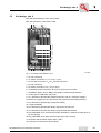
Edition
MOVIDRIVE® MD_60A
09/2001
Operating Instructions
1053 2617 / EN
SEW-EURODRIVE
1 Important Notes...................................................................................................... 4
2 Safety Notes ........................................................................................................... 6
3 Unit Design ............................................................................................................. 7
3.1 Unit designation, nameplates and scope of supply........................................ 7
3.2 Unit design, size 1.......................................................................................... 8
3.3 Unit design, size 2.......................................................................................... 9
3.4 Unit design, size 3........................................................................................ 10
3.5 Unit design, size 4........................................................................................ 11
3.6 Unit design, size 5........................................................................................ 12
4 Installation ............................................................................................................ 13
4.1 Installation instructions for basic unit ........................................................... 13
4.2 UL compliant installation .............................................................................. 17
4.3 Power shield clamp ...................................................................................... 18
4.4 Touch guard ................................................................................................. 19
4.5 Wiring diagram, basic unit............................................................................ 20
4.6 Assignment of braking resistors, chokes and filters ..................................... 23
4.7 System bus (SBus) connection .................................................................... 26
4.8 RS-485 interface connection........................................................................ 27
4.9 Connection option USS21A (RS-232 and RS-485)...................................... 28
4.10 Combination of options ................................................................................ 29
4.11 Installing and removing option pcbs............................................................. 30
4.12 Connection and terminal description of the DIO11A option ......................... 32
4.13 Encoder and resolver connection................................................................. 34
I
0
5 Startup................................................................................................................... 43
5.1 General startup instructions ......................................................................... 43
5.2 Preliminary work and resources................................................................... 45
5.3 Startup with the DBG11A keypad ................................................................ 46
5.4 Startup with a PC and MOVITOOLS............................................................ 53
5.5 Starting the motor ........................................................................................ 54
5.6 Complete parameter list ............................................................................... 57
6 Operation and Service ......................................................................................... 66
6.1 Operating displays ....................................................................................... 66
6.2 Fault information .......................................................................................... 70
6.3 Error messages and list of faults.................................................................. 71
6.4 SEW Electronics Service ............................................................................. 77
kVA
i
f
n
P Hz
7 Technical Data ...................................................................................................... 78
7.1 General technical data ................................................................................. 78
7.2 MOVIDRIVE® MD_60A...-5_3 (400/500 V units) ......................................... 79
7.3 MOVIDRIVE® MD_60A...-2_3 (230 V units) ................................................ 84
7.4 MOVIDRIVE® MD_60A electronics data ..................................................... 88
8 Abbreviation Key and Index ................................................................................ 89
Abbreviation Key .................................................................................................... 89
Index ..................................................................................................................... 90
Address List
MOVIDRIVE® MD_60A Operating Instructions
3
1
Important Notes
Safety and
warning
instructions
Always follow the safety and warning instructions contained in this publication!
Electrical hazard
Possible consequences: Severe or fatal injuries.
Hazard
Possible consequences: Severe or fatal injuries.
Hazardous situation
Possible consequences: Slight or minor injuries.
Harmful situation
Possible consequences: Damage to the unit and the
environment.
Tips and useful information.
A requirement of fault-free operation and fulfillment of any rights to claim under
guarantee is that the information in the operating instructions is adhered to.
Consequently, read the operating instructions before you start working with the unit!
The operating instructions contain important information about servicing; as a
result, they should be kept in the vicinity of the unit.
Designated use
MOVIDRIVE® MD_60A drive inverters are intended for use in industrial and commercial
systems for the operation of AC asynchronous motors or permanent-field AC
synchronous motors. These motors must be suitable for operation with frequency
inverters. No other loads may be connected to the units.
MOVIDRIVE® MD_60A drive inverters are units intended for stationary installation in
switch cabinets. All instructions referring to the technical data and the permissible
conditions where the unit is operated must be followed.
Do not start up the unit (take it into operation in the designated fashion) until you have
established that the machine complies with the EMC Directive 89/336/EEC and that the
conformity of the end product has been determined in accordance with the Machinery
Directive 89/392/EEC (with reference to EN 60204).
4
MOVIDRIVE® MD_60A Operating Instructions
Application
environment
The following uses are forbidden unless measures are expressly taken to make
them possible:
•
Use in explosion-proof areas
•
Use in areas exposed to harmful oils, acids, gases, vapors, dust, radiation, etc.
•
Use in non-stationary applications which are subject to mechanical vibration and
shock loads in excess of the requirements in EN 50178
Safety functions
MOVIDRIVE® MD_60A drive inverters must not perform any safety functions without a
higher-level safety precaution system.
To ensure the safety of people and systems, higher-level safety precaution systems
must be in operation.
Waste disposal
Please follow the current instructions: Disposal must be carried out in accordance with
the material structure and the regulations in force, for instance as:
•
Electronics scrap (printed-circuit boards)
•
Plastic (housing)
•
Sheet metal
•
Copper
etc.
MOVIDRIVE® MD_60A Operating Instructions
5
2
Safety Notes
Installation and
startup
Operation and
servicing
6
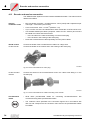
•
Never install damaged products or take them into operation.Please submit a
complaint to the transport company immediately in the event of damage.
•
Installation, startup and service work only by trained personnel observing
applicable accident prevention regulations and operating instructions! The
regulations in force (e.g. EN 60204, VBG 4, DIN-VDE 0100/0113/0160) must also be
complied with.
•
Follow the specific instructions during installation and startup of the motor and
the brake!
•
Make sure that preventive measures and protection devices correspond to the
applicable regulations (e.g. EN 60204 or EN 50178).
Required preventive measures:
Grounding the unit
Required protection device:
Overcurrent protection devices
•
The unit meets all requirements for reliable isolation of power and electronics
connections in accordance with EN 50178. All connected circuits must also satisfy
the requirements for reliable isolation so as to guarantee reliable isolation.
•
Take suitable measures (e.g. disconnecting the electronics terminal block) to
ensure that the connected motor does not start up automatically when the inverter
is switched on.
•
Disconnect the unit from the supply system prior to removing the protective
cover. Dangerous voltages may still be present for up to 10 minutes after mains
disconnection.
•
The unit has IP 00 enclosure with the protective cover removed. Dangerous
voltages are present on all subassemblies except for the control electronics. The
unit must be closed during operation.
•
Dangerous voltages are present at the output terminals and the cables and
motor terminals connected to them when the unit is switched on. This also
applies even when the unit is inhibited and the motor at a standstill.
•
Just because the operation LED and other display elements have gone out does
not mean that the unit has been disconnected from the supply system and is deenergized.
•
Safety functions inside the unit or a mechanical blockage may cause the motor
to stop. The removal of the source of the malfunction or a reset can result in an
automatic restart of the drive. If, for safety reasons, this is not permissible for the
driven machine, the unit must be disconnected from the supply system before
correcting the fault. In such cases, it is also forbidden for the "Auto reset" function
(P841) to be activated.
•
The inverter output may only be switched when the output stage is inhibited.
MOVIDRIVE® MD_60A Operating Instructions
Unit designation, nameplates and scope of supply
3
Unit Design
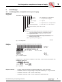
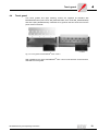
3.1
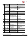
Unit designation, nameplates and scope of supply
Sample unit
designation
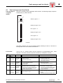
MOVIDRIVE® MDV 60 A 0055-5A3-4-00
Version
Quadrants
Type of supply
Input filter
Rated supply voltage
00 = Standard / 0T = Applications
4 = 4Q (with brake chopper)
3 = 3-phase
A = implemented / 0 = not implemented
5 = 380...500 VAC / 2 = 200...240 VAC
Recommended motor power 0055 = 5.5 kW
Version A
Type series
Type: MDF = flux control mode without encoder for asynchronous motors
only VFC operating modes (VFC = Voltage Flux Control)
MDV = field-oriented control mode without and with encoder for
asynchronous motors
VFC and CFC operating modes (CFC = Current Flux Control)
MDS = flux control mode with resolver for synchronous motors
SERVO operating modes
MDR = regenerative power supply unit
00880BEN
Fig. 1: Unit designation
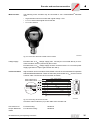
Sample
nameplate
The overall nameplate is attached to the side of the unit.
01318AXX
Fig. 2: Overall nameplate
Furthermore, a type label is attached to the front of the control unit (above the
TERMINAL option slot).
01322AXX
Fig. 3: Type label
Scope of delivery
•
All sizes: Connector housing for signal terminals (X10 – X13), connected.
•
In addition, with size 1: Plug housing for the power terminals (X1 – X4), connected.
•
In addition, with sizes 1 and 2: Power shield clamp.
•
In addition, with sizes 4 and 5: Touch guard for the power terminals.
MOVIDRIVE® MD_60A Operating Instructions
7
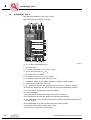
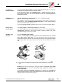
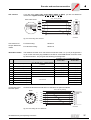
Unit design, size 1
3.2
Unit design, size 1
MD_60A-5A3 (400/500 V units): 0015 – 0040
MD_60A-2A3 (230 V units): 0015 – 0037
1
2
6
7
8
9
10
11
12
13
14
15
16
17
3
4 5
01245BXX
Fig. 4: Unit design, MOVIDRIVE® size 1
1. X1: Mains connection L1 (1) / L2 (2) / L3 (3), separable
2. X4: DC link connection -Uz / +Uz and PE connection, separable
3. X2: Motor connection U (4) / V (5) / W (6), separable
4. Connection for power shield clamp (not visible)
5. X3: Braking resistor connection R+ (8) / R- (9) and PE connection, separable
6. TERMINAL: Option slot for DBG11A keypad or USS21A serial interface
7. Control pcb on CONTROL option slot
8. X11: Electronics terminal strip (setpoint input AI1 and 10 V reference voltage)
9. Switch S11 (signal type AI1) and switch S12 (system bus terminating resistor)
10.X12: Electronics terminal strip system bus (SBus)
11.7-segment display
12.X10: Electronics terminal strip binary outputs and TF/TH input
13.X13: Electronics terminal strip binary inputs and RS-485 interface
14.Only MDV/MDS, X14: Incremental encoder simulation or external encoder input (9pin sub D plug)
15.Only MDV/MDS, X15: Motor encoder input (9-pin sub D socket)
16.OPTION1 and OPTION2: Option slots 1 and 2
17.Connection for electronics shield clamps
8
MOVIDRIVE® MD_60A Operating Instructions
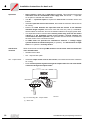
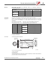
Unit design, size 2
3.3
Unit design, size 2
MD_60A-5A3 (400/500 V units): 0055 – 0110
MD_60A-2A3 (230 V units): 0055 / 0075
1
2
6
7
8
9
10
11
12
13
14
15
16
17
3
4
5
Fig. 5: Unit design, MOVIDRIVE® size 2
00895BXX
1. X1: Mains connection L1 (1) / L2 (2) / L3 (3)
2. X4: DC link connection -UZ / +UZ and PE connection
3. X2: Motor connection U (4) / V (5) / W (6) (not visible)
4. Connection for power shield clamp (not visible)
5. X3: Braking resistor connection R+ (8) / R- (9) and PE connection (not visible)
6. TERMINAL: Option slot for DBG11A keypad or USS21A serial interface
7. Control pcb on CONTROL option slot
8. X11: Electronics terminal strip (setpoint input AI1 and 10 V reference voltage)
9. Switch S11 (signal type AI1) and switch S12 (system bus terminating resistor)
10.X12: Electronics terminal strip system bus (SBus)
11.7-segment display
12.X10: Electronics terminal strip binary outputs and TF/TH input
13.X13: Electronics terminal strip binary inputs and RS-485 interface
14.Only MDV/MDS, X14: Incremental encoder simulation or external encoder input (9pin sub D plug)
15.Only MDV/MDS, X15: Motor encoder input (9-pin sub D socket)
16.OPTION1 and OPTION2: Option slots 1 and 2
17.Connection for electronics shield clamps
MOVIDRIVE® MD_60A Operating Instructions
9
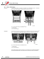
Unit design, size 3
3.4
Unit design, size 3
MD_60A-503 (400/500 V units): 0150 – 0300
MD_60A-203 (230 V units): 0110 / 0150
1
2
3
7
8
9
10
11
12
13
14
15
16
17
18
4
5
6
01248BXX
Fig. 6: Unit design, MOVIDRIVE® size 3
1. PE connections
2. X1: Mains connection L1 (1) / L2 (2) / L3 (3)
3. X4: DC link connection -UZ / +UZ
4. PE connections (not visible)
5. X2: Motor connection U (4) / V (5) / W (6)
6. X3: Braking resistor connection R+ (8) / R- (9)
7. TERMINAL: Option slot for DBG11A keypad or USS21A serial interface
8. Control pcb on CONTROL option slot
9. X11: Electronics terminal strip (setpoint input AI1 and 10 V reference voltage)
10.Switch S11 (signal type AI1) and switch S12 (system bus terminating resistor)
11.X12: Electronics terminal strip system bus (SBus)
12.7-segment display
13.X10: Electronics terminal strip binary outputs and TF/TH input
14.X13: Electronics terminal strip binary inputs and RS-485 interface
15.Only MDV/MDS, X14: Incremental encoder simulation or external encoder input (9pin sub D plug)
16.Only MDV/MDS, X15: Motor encoder input (9-pin sub D socket)
17.OPTION1 and OPTION2: Option slots 1 and 2
18.Connection for electronics shield clamps
10
MOVIDRIVE® MD_60A Operating Instructions
Unit design, size 4
3.5
Unit design, size 4
MD_60A-503 (400/500 V units): 0370 / 0450
MD_60A-203 (230 V units): 0220 / 0300
1
2
3
7
8
9
10
11
12
13
14
15
16
17
18
4
5
6
Fig. 7: Unit design, MOVIDRIVE® size 4
01249BXX
1. X2: PE connection
2. X1: Mains connection L1 (1) / L2 (2) / L3 (3)
3. X4: DC link connection -UZ / +UZ and PE connection
4. X2: PE connection
5. X2: Motor connection U (4) / V (5) / W (6)
6. X3: Braking resistor connection R+ (8) / R- (9) and PE connection
7. TERMINAL: Option slot for DBG11A keypad or USS21A serial interface
8. Control pcb on CONTROL option slot
9. X11: Electronics terminal strip (setpoint input AI1 and 10 V reference voltage)
10.Switch S11 (signal type AI1) and switch S12 (system bus terminating resistor)
11.X12: Electronics terminal strip system bus (SBus)
12.7-segment display
13.X10: Electronics terminal strip binary outputs and TF/TH input
14.X13: Electronics terminal strip binary inputs and RS-485 interface
15.Only MDV/MDS, X14: Incremental encoder simulation or external encoder input (9pin sub D plug)
16.Only MDV/MDS, X15: Motor encoder input (9-pin sub D socket)
17.OPTION1 and OPTION2: Option slots 1 and 2
18.Connection for electronics shield clamps
MOVIDRIVE® MD_60A Operating Instructions
11
Unit design, size 5
3.6
Unit design, size 5
MD_60A-503 (400/500 V units): 0550 / 0750
1
2
3
7
8
9
10
11
12
13
14
15
16
17
18
4
5
6
01249BXX
Fig. 8: Unit design, MOVIDRIVE® size 5
1. X2: PE connection
2. X1: Mains connection L1 (1) / L2 (2) / L3 (3)
3. X4: DC link connection -UZ / +UZ and PE connection
4. X2: PE connection
5. X2: Motor connection U (4) / V (5) / W (6)
6. X3: Braking resistor connection R+ (8) / R- (9) and PE connection
7. TERMINAL: Option slot for DBG11A keypad or USS21A serial interface
8. Control pcb on CONTROL option slot
9. X11: Electronics terminal strip (setpoint input AI1 and 10 V reference voltage)
10.Switch S11 (signal type AI1) and switch S12 (system bus terminating resistor)
11.X12: Electronics terminal strip system bus (SBus)
12.7-segment display
13.X10: Electronics terminal strip binary outputs and TF/TH input
14.X13: Electronics terminal strip binary inputs and RS-485 interface
15.Only MDV/MDS, X14: Incremental encoder simulation or external encoder input (9pin sub D plug)
16.Only MDV/MDS, X15: Motor encoder input (9-pin sub D socket)
17.OPTION1 and OPTION2: Option slots 1 and 2
18.Connection for electronics shield clamps
12
MOVIDRIVE® MD_60A Operating Instructions
Installation instructions for basic unit
4
Installation
4.1
Installation instructions for basic unit
It is essential to comply with the safety notes during installation!
Tightening
torques
•
Only use genuine connection elements. Note the permitted tightening torques
of MOVIDRIVE® power terminals.
–
–
–
–
→
→
→
→
Size 1
Size 2
Size 3
Sizes 4 and 5
0.6 Nm (5.3 lb.in)
1.5 Nm (13.3 lb.in)
3.5 Nm (31 lb.in)
14 Nm (124 lb.in)
Nm (lb.in)!
02475AXX
Fig. 9: Note the tightening torques
Minimum
clearance and
mounting
position
•
Leave 100 mm (4 in) clearance at the top and bottom for optimum cooling. No
lateral clearance required; the units can be lined up side-by-side. With sizes 4 and 5,
do not install any components which are sensitive to high temperatures within 300
mm (11.81 in) of the top of the unit. Only install the units vertically. You must not
install them horizontally, tilted or upside down.
100 mm
(4 in)
E
Q
E
Q
E
Q
E
Q
100 mm
(4 in)
02474AXX
Fig. 10: Minimum clearance and installation position of the units
MOVIDRIVE® MD_60A Operating Instructions
13
Installation instructions for basic unit
Separate cable
ducts
•
Route power cables and electronics cables in separate cable ducts.
Input fuses and
earth-leakage
circuit breakers
•
Install the input fuses at the beginning of the supply system lead behind the
supply bus junction (→ Wiring diagram for basic unit, power section and brake).
•
Using an earth-leakage circuit breaker as the sole protection device is not
permitted. Earth-leakage currents > 3.5 mA can arise during normal operation of
the inverter.
Supply system
and brake
contactors
•
Only use contactors in utilization category AC-3 (IEC 158-1) as supply system
and brake contactors.
PE mains
connection (→
EN 50178)
•
With a supply system lead < 10 mm2 (AWG 8): Lay a second PE conductor with
the cross section of the supply system lead in parallel to the protective earth via
separate terminals or use a copper protective earth with a cross section of 10
mm2 (AWG 8).
•
With a supply system lead ≥ 10 mm2 (AWG 8): Lay a copper protective earth
with the cross section of the supply system lead.
IT systems
•
SEW recommends using earth-leakage monitors with a pulse code measuring
process in voltage supply systems with a non-earthed star point (IT systems). This
avoids mis-tripping of the earth-leakage monitor due to the earth capacitance of the
inverter.
Cross sections
•
Supply system lead: Cross section according to nominal input current Iin at rated
load.
•
Motor lead: Cross section according to output rated current IN.
•
Electronics cables:
– One core per terminal 0.20 – 2.5 mm 2 (AWG 24 – 12)
– Two cores per terminal 0.20 – 1 mm2 (AWG 24 – 17)
Unit output
•
Only connect ohmic/inductive loads (motors). Never connect capacitive loads!
E
Q
02476AXX
Fig. 11: Only connect ohmic/inductive loads; do not connect capacitive loads
14
MOVIDRIVE® MD_60A Operating Instructions
Installation instructions for basic unit
Connecting
braking resistors
Operating
braking resistors
Binary inputs /
binary outputs
Shielding and
earthing
•
Use two closely twisted cables or a 2-core shielded power cable. Cross section
according to the output rated current of the inverter.
•
Protect the braking resistor with a bimetallic relay (→ Wiring diagram for basic unit,
power section and brake). Set the trip current according to the technical data of
the braking resistor.
•
The connection leads to the braking resistors carry a high DC voltage
(approx. 900 V) during rated operation.
•
The surfaces of the braking resistors get very hot when the braking resistors are
loaded with PN. Select a suitable installation position. As a rule, braking resistors
are mounted on the switch cabinet roof.
•
Install the flat-type braking resistors together with the appropriate touch guard.
•
The binary inputs are electrically isolated by optocouplers.
•
The binary outputs are short-circuit proof, although they are not interferencevoltage-proof (exception: relay output DOØ1). External voltage can cause
irreparable damage to the binary outputs.
•
Only use shielded control cables.
•
Connect the shield by the shortest possible route and make sure it is earthed
over a wide area at both ends. You can ground one end of the shield via a
suppression capacitor (220 nF / 50 V) to avoid ground loops. If using double-shielded
cables, ground the outer shield on the inverter end and the inner shield on the other
end.
bbbbbbbbbbbbbbbbbbbbbbbbbbbbbbbbbb
aaaaaaaaaaaaaaaaaaaaaaaaaaaaaaaaaa
aaaaaaaaaaaaaaaaaaaaaaaaaaaaaaaaaa
bbbbbbbbbbbbbbbbbbbbbbbbbbbbbbbbbb
aaaaaaaaaaaaaaaaaaaaaaaaaaaaaaaaaa
bbbbbbbbbbbbbbbbbbbbbbbbbbbbbbbbbb
aaaaaaaaaaaaaaaaaaaaaaaaaaaaaaaaaa
bbbbbbbbbbbbbbbbbbbbbbbbbbbbbbbbbb
aaaaaaaaaaaaaaaaaaaaaaaaaaaaaaaaaa
bbbbbbbbbbbbbbbbbbbbbbbbbbbbbbbbbb
aaaaaaaaaaaaaaaaaaaaaaaaaaaaaaaaaa
bbbbbbbbbbbbbbbbbbbbbbbbbbbbbbbbbb
aaaaaaaaaaaaaaaaaaaaaaaaaaaaaaaaaa
bbbbbbbbbbbbbbbbbbbbbbbbbbbbbbbbbb
aaaaaaaaaaaaaaaaaaaaaaaaaaaaaaaaaa
bbbbbbbbbbbbbbbbbbbbbbbbbbbbbbbbbb
aaaaaaaaaaaaaaaaaaaaaaaaaaaaaaaaaa
bbbbbbbbbbbbbbbbbbbbbbbbbbbbbbbbbb
aaaaaaaaaaaaaaaaaaaaaaaaaaaaaaaaaa
bbbbbbbbbbbbbbbbbbbbbbbbbbbbbbbbbb
aaaaaaaaaaaaaaaaaaaaaaaaaaaaaaaaaa
bbbbbbbbbbbbbbbbbbbbbbbbbbbbbbbbbb
aaaaaaaaaaaaaaaaaaaaaaaaaaaaaaaaaa
bbbbbbbbbbbbbbbbbbbbbbbbbbbbbbbbbb
aaaaaaaaaaaa
bbbbbbbbbbbb
aaaaaaaaaaaaaaaaaaaaaaaaaaaaaaaaaa
bbbbbbbbbbbbbbbbbbbbbbbbbbbbbbbbbb
aaaaaaaaaaaa
bbbbbbbbbbbb
aaaaaaaaaa
bbbbbbbbbb
aaaaaaaaaaaaaaaaaaaaaaaaaaaaaaaaaa
bbbbbbbbbbbbbbbbbbbbbbbbbbbbbbbbbb
aaaaaa
bbbbbb
aaaaaaaaaaaa
bbbbbbbbbbbb
aaaaaaaaaa
bbbbbbbbbb
aaaaaaaaaaaaaaaaaaaaaaaaaaaaaaaaaa
bbbbbbbbbbbbbbbbbbbbbbbbbbbbbbbbbb
aaaaaa
bbbbbb
aaaaaaaaaaaa
bbbbbbbbbbbb
aaaaaaaaaa
bbbbbbbbbb
aaaaaaaaaaaaaaaaaaaaaaaaaaaaaaaaaa
bbbbbbbbbbbbbbbbbbbbbbbbbbbbbbbbbb
aaaaaa
bbbbbb
aaaaaaaaaaaa
bbbbbbbbbbbb
aaaaaaaaaa
bbbbbbbbbb
aaaaaaaaaaaaaaaaaaaaaaaaaaaaaaaaaa
bbbbbbbbbbbbbbbbbbbbbbbbbbbbbbbbbb
aaaaaa
bbbbbb
aaaaaaaaaaaa
bbbbbbbbbbbb
aaaaaaaaaa
bbbbbbbbbb
aaaaaaaaaaaaaaaaaaaaaaaaaaaaaaaaaa
bbbbbbbbbbbbbbbbbbbbbbbbbbbbbbbbbb
aaaaaa
bbbbbb
aaaaaaaaaaaa
bbbbbbbbbbbb
aaaaaaaaaa
bbbbbbbbbb
aaaaaaaaaaaaaaaaaaaaaaaaaaaaaaaaaa
bbbbbbbbbbbbbbbbbbbbbbbbbbbbbbbbbb
aaaaaa
bbbbbb
aaaaaaaaaaaa
bbbbbbbbbbbb
aaaaaaaaaa
bbbbbbbbbb
aaaaaaaaaaaaaaaaaaaaaaaaaaaaaaaaaa
bbbbbbbbbbbbbbbbbbbbbbbbbbbbbbbbbb
aaaaaa
bbbbbb
aaaaaaaaaaaa
bbbbbbbbbbbb
aaaaaaaaaa
bbbbbbbbbb
aaaaaaaaaaaaaaaaaaaaaaaaaaaaaaaaaa
bbbbbbbbbbbbbbbbbbbbbbbbbbbbbbbbbb
aaaaaa
bbbbbb
aaaaaaaaaaaa
bbbbbbbbbbbb
aaaaaaaaaa
bbbbbbbbbb
bbbbbbbbbbbbbbbbbbbbbbbbbbbbbbbbbb
aaaaaaaaaaaaaaaaaaaaaaaaaaaaaaaaaa
aaaaaaaaaaaaaaaaaaaaaaaaaaaaaaaaaa
bbbbbbbbbbbbbbbbbbbbbbbbbbbbbbbbbb
aaaaaaaaaaaaaaaaaaaaaaaaaaaaaaaaaa
bbbbbbbbbbbbbbbbbbbbbbbbbbbbbbbbbb
aaaaaaaaaaaaaaaaaaaaaaaaaaaaaaaaaa
bbbbbbbbbbbbbbbbbbbbbbbbbbbbbbbbbb
aaaaaaaaaaaaaaaaaaaaaaaaaaaaaaaaaa
bbbbbbbbbbbbbbbbbbbbbbbbbbbbbbbbbb
aaaaaaaaaaaaaaaaaaaaaaaaaaaaaaaaaa
bbbbbbbbbbbbbbbbbbbbbbbbbbbbbbbbbb
aaaaaaaaaaaaaaaaaaaaaaaaaaaaaaaaaa
bbbbbbbbbbbbbbbbbbbbbbbbbbbbbbbbbb
aaaaaaaaaaaaaaaaaaaaaaaaaaaaaaaaaa
bbbbbbbbbbbbbbbbbbbbbbbbbbbbbbbbbb
aaaaaaaaaaaaaaaaaaaaaaaaaaaaaaaaaa
bbbbbbbbbbbbbbbbbbbbbbbbbbbbbbbbbb
aaaaaaaaaaaaaaaaaaaaaaaaaaaaaaaaaa
bbbbbbbbbbbbbbbbbbbbbbbbbbbbbbbbbb
aaaaaaaaaaaaaaaaaaaaaaaaaaaaaaaaaa
bbbbbbbbbbbbbbbbbbbbbbbbbbbbbbbbbb
aaaaaaaaaaaaaaaaaaaaaaaaaaaaaaaaaa
bbbbbbbbbbbbbbbbbbbbbbbbbbbbbbbbbb
aaaaaaaaaaaa
bbbbbbbbbbbb
aaaaaaaaaaaaaaaaaaaaaaaaaaaaaaaaaa
bbbbbbbbbbbbbbbbbbbbbbbbbbbbbbbbbb
aaaaaaaaaaaa
bbbbbbbbbbbb
aaaaaaaaaaaaaaaaaaaaaaaaaaaaaaaaaa
bbbbbbbbbbbbbbbbbbbbbbbbbbbbbbbbbb
aaaaaaaaaaaa
bbbbbbbbbbbb
aaaaaaaaaaaaaaaaaaaaaaaaaaaaaaaaaa
bbbbbbbbbbbbbbbbbbbbbbbbbbbbbbbbbb
aaaaaaaaaaaa
bbbbbbbbbbbb
aaaaaaaaaaaaaaaaaaaaaaaaaaaaaaaaaa
bbbbbbbbbbbbbbbbbbbbbbbbbbbbbbbbbb
aaaaaaaaaaaa
bbbbbbbbbbbb
aaaaaaaaaaaaaaaaaaaaaaaaaaaaaaaaaa
bbbbbbbbbbbbbbbbbbbbbbbbbbbbbbbbbb
aaaaaaaaaaaa
bbbbbbbbbbbb
aaaaaaaaaaaaaaaaaaaaaaaaaaaaaaaaaa
bbbbbbbbbbbbbbbbbbbbbbbbbbbbbbbbbb
aaaaaaaaaaaa
bbbbbbbbbbbb
aaaaaaaaaaaaaaaaaaaaaaaaaaaaaaaaaa
bbbbbbbbbbbbbbbbbbbbbbbbbbbbbbbbbb
aaaaaaaaaaaa
bbbbbbbbbbbb
aaaaaaaaaaaaaaaaaaaaaaaaaaaaaaaaaa
bbbbbbbbbbbbbbbbbbbbbbbbbbbbbbbbbb
aaaaaaaaaaaa
bbbbbbbbbbbb
aaaaaaaaaaaaaaaaaaaaaaaaaaaaaaaaaa
bbbbbbbbbbbbbbbbbbbbbbbbbbbbbbbbbb
aaaaaaaaaaaa
bbbbbbbbbbbb
bbbbbbbbbbbbbbbbbbbbbbbbbbbbbbbbbb
aaaaaaaaaaaaaaaaaaaaaaaaaaaaaaaaaa
aaaaaaaaaaaaaaaaaaaaaaaaaaaaaaaaaa
bbbbbbbbbbbbbbbbbbbbbbbbbbbbbbbbbb
aaaaaaaaaaaaaaaaaaaaaaaaaaaaaaaaaa
bbbbbbbbbbbbbbbbbbbbbbbbbbbbbbbbbb
aaaaaaaaaaaaaaaaaaaaaaaaaaaaaaaaaa
bbbbbbbbbbbbbbbbbbbbbbbbbbbbbbbbbb
aaaaaaaaaaaaaaaaaaaaaaaaaaaaaaaaaa
bbbbbbbbbbbbbbbbbbbbbbbbbbbbbbbbbb
aaaaaaaaaaaaaaaaaaaaaaaaaaaaaaaaaa
bbbbbbbbbbbbbbbbbbbbbbbbbbbbbbbbbb
aaaaaaaaaaaaaaaaaaaaaaaaaaaaaaaaaa
bbbbbbbbbbbbbbbbbbbbbbbbbbbbbbbbbb
aaaaaaaaaaaaaaaaaaaaaaaaaaaaaaaaaa
bbbbbbbbbbbbbbbbbbbbbbbbbbbbbbbbbb
aaaaaaaaaaaaaaaaaaaaaaaaaaaaaaaaaa
bbbbbbbbbbbbbbbbbbbbbbbbbbbbbbbbbb
aaaaaaaaaaaaaaaaaaaaaaaaaaaaaaaaaa
bbbbbbbbbbbbbbbbbbbbbbbbbbbbbbbbbb
aaaaaaaaaaaaaaaaaaaaaaaaaaaaaaaaaa
bbbbbbbbbbbbbbbbbbbbbbbbbbbbbbbbbb
aaaaa
bbbbb
aaaaaaaaaaaaaaaaaaaaaaaaaaaaaaaaaa
bbbbbbbbbbbbbbbbbbbbbbbbbbbbbbbbbb
aaaaa
bbbbb
aaaaaaaaaaaa
bbbbbbbbbbbb
bbbb
aaaa
aaaaaaaaaaaaaaaaaaaaaaaaaaaaaaaaaa
bbbbbbbbbbbbbbbbbbbbbbbbbbbbbbbbbb
aaaaa
bbbbb
aaaaaaaaaaaa
bbbbbbbbbbbb
bbbb
aaaa
aaaaaaaaaaaaaaaaaaaaaaaaaaaaaaaaaa
bbbbbbbbbbbbbbbbbbbbbbbbbbbbbbbbbb
aaaaaaaaaaaa
bbbbbbbbbbbb
aaaaaaaaaaaaaaaaaaaaaaaaaaaaaaaaaa
bbbbbbbbbbbbbbbbbbbbbbbbbbbbbbbbbb
aaaaaaaaaaaa
bbbbbbbbbbbb
aaaaaaaaaaaaaaaaaaaaaaaaaaaaaaaaaa
bbbbbbbbbbbbbbbbbbbbbbbbbbbbbbbbbb
aaaaaaaaaaaa
bbbbbbbbbbbb
aaaaaaaaaaaaaaaaaaaaaaaaaaaaaaaaaa
bbbbbbbbbbbbbbbbbbbbbbbbbbbbbbbbbb
aaaaaaaaaaaa
bbbbbbbbbbbb
aaaaaaaaaaaaaaaaaaaaaaaaaaaaaaaaaa
bbbbbbbbbbbbbbbbbbbbbbbbbbbbbbbbbb
aaaaaaaaaaaa
bbbbbbbbbbbb
aaaaaaaaaaaaaaaaaaaaaaaaaaaaaaaaaa
bbbbbbbbbbbbbbbbbbbbbbbbbbbbbbbbbb
aaaaaaaaaaaa
bbbbbbbbbbbb
aaaaaaaaaaaaaaaaaaaaaaaaaaaaaaaaaa
bbbbbbbbbbbbbbbbbbbbbbbbbbbbbbbbbb
aaaaaaaaaaaa
bbbbbbbbbbbb
aaaaaaaaaaaaaaaaaaaaaaaaaaaaaaaaaa
bbbbbbbbbbbbbbbbbbbbbbbbbbbbbbbbbb
aaaaaaaaaaaa
bbbbbbbbbbbb
aaaaaaaaaaaaaaaaa
bbbbbbbbbbbbbbbbb
aaaaaaaaaaaaaaaaa
bbbbbbbbbbbbbbbbb
aaaaaaaaaaaaaaaaa
bbbbbbbbbbbbbbbbb
aaaaaaaaaaaaaaaaa
bbbbbbbbbbbbbbbbb
aaaaaaaaaaaa
bbbbbbbbbbbb
aaaaaaaaaaaaaaaaa
bbbbbbbbbbbbbbbbb
bbbbbbbbbbbb
aaaaaaaaaaaa
aaaaaaaaaaaaaaaaa
bbbbbbbbbbbbbbbbb
aaaaaaaaaaaa
bbbbbbbbbbbb
aaaaaaaaaaaaaaaaa
bbbbbbbbbbbbbbbbb
aaaaaaaaaaaa
bbbbbbbbbbbb
aaaaaaaaaaaaaaaaa
bbbbbbbbbbbbbbbbb
aaaaaaaaaaaa
bbbbbbbbbbbb
aaaaaaaaaaaaaaaaa
bbbbbbbbbbbbbbbbb
aaaaaaaaaaaa
bbbbbbbbbbbb
aaaaaaaaaaaaaaaaa
bbbbbbbbbbbbbbbbb
aaaaaaaaaaaa
bbbbbbbbbbbb
aaaaaaaaaaaaaaaaa
bbbbbbbbbbbbbbbbb
aaaaaaaaaaaa
bbbbbbbbbbbb
aaaaaaaaaaaaaaaaa
bbbbbbbbbbbbbbbbb
aaaaaaaaaaaa
bbbbbbbbbbbb
aaaaaaaaaaaaaaaaa
bbbbbbbbbbbbbbbbb
aaaaaaaaaaaa
bbbbbbbbbbbb
00755BXX
Fig. 12: Example of correct shield connection with metal clamp (shield clamp) or metal cable
gland
•
Shielding can also be achieved by laying the cables in grounded sheet metal
ducts or metal pipes. In this case, the power cables and control cables should
be laid separately.
•
Provide high frequency compatible grounding for the inverter and all additional
units (wide area metal-on-metal contact between the unit housing and ground, e.g.
unpainted switch cabinet mounting panel).
MOVIDRIVE® MD_60A Operating Instructions
15
Installation instructions for basic unit
Input filter
Interference
emission
HD... output choke
•
Sizes 1 and 2 are fitted with an input filter as standard. This input filter ensures that
limit value class A is maintained on the supply side. Use an NF...-... input filter
as an option to maintain the class B limit.
•
The NF...-... input filter option is required for sizes 3 to 5 to maintain class A and
B limits.
•
Install the input filter close to the inverter, but outside the minimum clearance area
for cooling.
•
Restrict the cable between the input filter and the inverter to the absolute
minimum length required, and never more than 400 mm (15.8 in). Unshielded,
twisted cables are sufficient. Also use unshielded cables for the supply system lead.
•
This input filter must be mounted either directly at the entry point into the switch
cabinet or in the immediate vicinity of the inverter if several inverters are
connected to the same input filter. The input filter must be chosen on the basis of
the total current of the connected inverters.
•
No EMC limits are specified for interference emission in voltage supply
systems without an earthed star point (IT systems). The effectiveness of input
filters in IT systems is severely limited.
SEW recommends the following EMC measures on the motor side to maintain the
class A and B limits:
•
Shielded motor cable
•
HD... output choke option
•
Install the output choke close to the inverter, but outside the minimum clearance
for cooling.
•
Route all three phases together through the output choke. Do not route the PE
conductor through the output choke!
4
MOVIDRIVE
5
6
®
n=5
HD...
PE U V W
(1)
05003AXX
Fig. 13: Connecting HD... output chokes
(1) = Motor cable
16
MOVIDRIVE® MD_60A Operating Instructions
UL compliant installation
4.2
UL compliant installation
Please note the following points for UL compliant installation:
•
Only use copper cables with the following temperature ranges as connection
leads:
•
•
•
The permitted tightening torques for MOVIDRIVE® power terminals are:
–
–
–
–
•
For MOVIDRIVE® MD_60A0015 – 0300 temperature range 60/75 °C
For MOVIDRIVE® MD_60A0370 – 0750 temperature range 75/90 °C
Size 1
Size 2
Size 3
Sizes 4 and 5
→
→
→
→
0.6 Nm (5.3 lb.in)
1.5 Nm (13.3 lb.in)
3.5 Nm (31 lb.in)
14 Nm (124 lb.in)
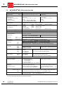
MOVIDRIVE® drive inverters are suitable for operation in voltage power systems
with an earthed star point (TN and TT systems) which can supply a max. current
in accordance with the following tables and which have a max. voltage of 500 VAC
for MOVIDRIVE® MD_60A...-5_3 (400/500 V units) and 240 VAC for MOVIDRIVE®
MD_60A...2_3 (230 V units). The performance data of the fuses must not exceed the
values in the tables.
400/500 V units
MOVIDRIVE®
MD_60A...5_3
Max. supply current
Max. supply voltage
Fuses
0015/0022/0030/0040
10000 AAC
500 VAC
30 A / 600 V
0055/0075/0110
10000 AAC
500 VAC
30 A / 600 V
0150/0220
5000 AAC
500 VAC
175 A / 600 V
0300
5000 AAC
500 VAC
225 A / 600 V
0370/0450
10000 AAC
500 VAC
350 A / 600 V
0550/0750
10000 AAC
500 VAC
500 A / 600 V
MOVIDRIVE®
MD_60A...2_3
Max. supply current
Max. supply voltage
Fuses
0015/0022/0037
5000 AAC
240 VAC
30 A / 250 V
0055/0075
5000 AAC
240 VAC
30 A / 250 V
0110
5000 AAC
240 VAC
175 A / 250 V
0150
5000 AAC
240 VAC
225 A / 250 V
0220/0300
10000 AAC
240 VAC
350 A / 250 V
230 V units
•
Only use tested units with a limited output voltage (Vmax = 30 VDC) and limited
output current (I ≤ 8 A) as an external 24 VDC voltage source.
UL certification does not apply to operation in voltage supply systems with a nonearthed star point (IT systems).
MOVIDRIVE® MD_60A Operating Instructions
17
Power shield clamp
4.3
Power shield clamp
For size 1
A power shield clamp is supplied as standard with MOVIDRIVE ® size 1. Install this
power shield clamp together with the retaining screws of the unit.
1
2
02012BXX
Fig. 14: Power shield clamp for MOVIDRIVE® size 1
1. Shield clamp
2. PE connection (y)
For size 2
A power shield clamp with 2 retaining screws is supplied as standard with MOVIDRIVE ®
size 2. Install this power shield clamp together with the two retaining screws on X6.
1
Fig. 15: Power shield clamp for MOVIDRIVE® size 2
2
01469BXX
1. Shield clamp
2. PE connection (y)
Power shield clamps provide you with a very convenient way of installing the shield for
the motor and brake leads. Fit the shield and PE conductor as shown in the figures.
18
MOVIDRIVE® MD_60A Operating Instructions
Touch guard
4.4
Touch guard
Two touch guards and eight retaining screws are supplied as standard with
MOVIDRIVE® size 4 (500 V units: MD_60A0370/0450; 230 V units: MD_60A0220/0300)
and size 5 (MD_60A0550/0750). Install the touch guard on the two hood covers for the
power section terminals.
Fig. 16: Touch guard for MOVIDRIVE® sizes 4 and 5
01470BXX
With installed touch guard, MOVIDRIVE® size 4 and 5 units achieve IP10 enclosure,
IP00 without touch guard.
MOVIDRIVE® MD_60A Operating Instructions
19
Wiring diagram, basic unit
4.5
Wiring diagram, basic unit
Connection of the power section and brake
L1
L2
L3
PE
F11/F12/F13
K11
(AC-3)
Protective earth conductor (shield)
L1 L2
VAC
VAC
F14/F15
F14/F15
L3
Option NF... input filter
VAC
DC-link
connection *
8 7 y
L1' L2' L3'
y
F14/F15
1
2
3
L1 L2 L3
X1:
K11
(AC-3)
+VDC link PE
-VDC link
X4:
Power section
U
X10:3
DBØØ
X10:3
DBØØ
X10:2
DGND
K12
(AC-3)
4
5
X3:
+R -R PE
6
8
9
y
K12
(AC-3)
X10:2
DGND
1
BMK 2
3
4
13
14
15
y
X10:3
DBØØ
X2:
V W
white
1
BG 2
red
Brake connector** BGE 3
4
blue
CM (DY)
5
5 (1)
4 (2)
CT/CV/DT/DV/D:
3 (3)
simultaneous switch-off
PE
in the AC and DC circuits.
X10:2
DGND
1
BG 2
3
BGE 4
5
F16
white
y
red
blue
y
M
3- phase
BW...
affects
K11
CT/CV/DT/DV/D:
switch-off in the AC circuit.
CM/DFY71...112: simultaneous switch-off in the AC and DC circuits.
DFS56: 24 V supply of the brake without brake rectifier
05229AEN
Fig. 17: Wiring diagram, power section and brake
*
With sizes 1 and 2, there is no PE connection next to the mains connection terminals. In this case, use the PE
terminal next to the DC link connection.
**
Important:It is essential to adhere to the sequence of connections. Incorrect connection will lead to irreparable
damage to the brake.
A separate supply system lead is required for connecting the brake rectifier.
Powering it from the motor voltage is not permitted!
Always switch off the brake on the DC and AC sides under the following conditions:
– all hoist applications,
– drives which require a rapid brake reaction time and
– in CFC and SERVO operating modes.
Brake rectifier in
switch cabinet
20
Route the connection cables between the brake rectifier and the brake separately from
other power cables when installing the brake rectifier in the switch cabinet. Joint routing
is only permitted if the power cables are shielded.
MOVIDRIVE® MD_60A Operating Instructions
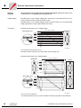
Wiring diagram, basic unit
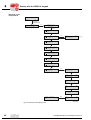
Control unit connection
0V5 - +
RS485
E
Q
0
1
2
3
4
5
6
7
8
9
A
b
c
d
E
F
H
t
Option
DBG11A
Keypad
7-segment display
Operating condition
Inverter not ready
Controller inhibit
No enable
Current at standstill
VFC operation
Speed control
Torque control
Hold control
Factory setting
Limit switch approached
Technology option
Not used
Reference travel IPOS
Flying restart
Not used
Fault indication (flashing)
Manual operation
Timeout active
-10V...+10V 0(4)...20mA
REF1
AI11
AI12
AGND
REF2
Select: I signal ↔ V signal*
system bus terminating resistor
TERMINAL
Option
USS21A
ser.interface
+10V
+
n1 (0...10V*;+/-10V;
0...20mA;4...20mA)
Ref.potential for analog signals
-10V
RS232
R11
X11:
X11:AI11/AI12
Control unit
CONTROL
1
2
3
4
5
I
S 11
S 12
ON OFF*
High level
control
X12:
system bus ref.potential
system bus high
system bus low
DGND 1
SC11 2
SC12 3
7-segment display
V
Binary
input
X13:
/Controller inhibit
CW/stop*
CCW/stop*
Enable/Rapid stop*
n11/n21*
n12/n22*
Reference X13:DIØØ...DIØ5
+24V output
Ref. potential for binary signals
RS-485 +
RS-485 -
DIØØ 1
DIØ1 2
DIØ2 3
DIØ3 4
DIØ4 5
DIØ5 6
DCOM** 7
VO24 8
DGND 9
ST11 10
ST12 11
Binary
outputs
Reference
Binary outputs
DGND
X14:
Incremental encoder
simulation
or external encoder
connection
(not on MDF)
6
1
9
5
X15:
Encoder (MDV)
or resolver (MDS)
connection
9
5
6
1
Note! Pin assignment for
connectors X14 and X15.
Not all connectors available have this pin assignment.
ϑ
TERMINAL
TF1***
1
DGND
2
DBØØ
3
DOØ1-C 4
DOØ1-NO 5
DOØ1-NC 6
DOØ2
7
VO24
8
VI24
9
DGND 10
K12
(AC-3)
24V
Depending on option,
connect external 24V supply
Shield plate or
shield terminal
Option
slots
OPTION1 OPTION2
CONTROL
OPTION2
OPTION1
X10:
TF/TH input
Ref. potential for binary signals
/Brake
Common relay contact
Ready for operation*
Contact normally open
Contact normally closed
/fault*
+24V output
+24V input
Reference potential for binary signals
(→ MOVIDRIVE
®
electronic data)
03975AEN
Fig. 18: Wiring diagram, control unit
*
Factory setting
**
If the binary inputs are connected to the 24 VDC voltage supply X13:8 "VO24", then jumper X13:7 to X13:9
(DCOM to DGND) on MOVIDRIVE®.
***
Factory setting: X10:1 (TF1) is jumpered to X10:2 (DGND). The jumper must be removed if a TF or TH is
connected to X10:1 and X10:2.
MOVIDRIVE® MD_60A Operating Instructions
21
4
Wiring diagram, basic unit
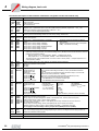
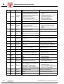
Functional description of the terminals of the basic unit (power section and control unit)
Terminal
Function
X1:1/2/3
X2:4/5/6
X3:8/9
X4:
L1/L2/L3
U/V/W
+R/-R
+UZ/-UZ
Mains connection
Motor connection
Braking resistor connection
DC link connection
X11:1
X11:2/3
X11:4
X11:5
REF1
AI11/12
AGND
REF2
+10 V (max. 3 mA) for setpoint potentiometer
Setpoint input n1 (differential input or input with AGND reference potential), signal form → P11_ / S11
Reference potential for analog signals (REF1, REF2, AI.., AO..)
-10 V (max. 3 mA) for setpoint potentiometer
Switch mode I signal (0(4) – 20 mA) ↔ U signal (-10 V – 0 – 10 V, 0 – 10 V), factory setting: V signal
Switch system bus terminating resistor on or off, factory setting: switched off
S11:
S12:
X12:1
X12:2/3
DGND
SC11/12
Reference potential system bus
System bus high/low
X13:1
X13:2
X13:3
X13:4
X13:5
X13:6
DIØØ
DIØ1
DIØ2
DIØ3
DIØ4
DIØ5
Binary input 1, with fixed assignment "/Controller
inhibit"
Binary input 2, factory setting "CW/stop"
Binary input 3, factory setting "CCW/stop"
Binary input 4, factory setting "Enable/rapid stop"
Binary input 5, factory setting "n11/n12"
Binary input 6, factory setting "n12/n22"
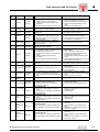
X13:7
DCOM
Reference for binary inputs X13:1 to X13:6 (DIØØ – DIØ5)
• Switching of binary inputs with +24 V external voltage: X13:7 (DCOM) must be connected to the reference
potential of the external voltage.
– Without jumper X13:7 – X13:9 (DCOM – DGND) → Isolated binary inputs
– With jumper X13:7 – X13:9 (DCOM – DGND) → Non-isolated binary inputs
•
22
•
•
The binary inputs are electrically isolated by
optocouplers.
Selection options for binary inputs 2 to 6 (DIØ1 –
DIØ5) → Parameter menu P60_
The binary inputs must be switched with +24 V from X13:8 or X10:8 (VO24) → Jumper required X13:7 –
X13:9 (DCOM – DGND).
X13:8
X13:9
X13:10
X13:11
VO24
DGND
ST11
ST12
Auxiliary supply output +24 V (max. 200 mA) for external command switches
Reference potential for binary signals
RS-485+
RS-485 -
X14:1
X14:2
X14:3
X14:4
X14:5
X14:6
X14:7
X14:8
X14:9
Not with
MDF60A
Signal track A (K1)
Signal track B (K2)
Signal track C (K0)
Switchover
Ref. potential DGND
Signal track A (K1)
Signal track B (K2)
Signal track C (K0)
+24 V (max. 180 mA)
X15:1
X15:2
X15:3
X15:4
X15:5
X15:6
X15:7
X15:8
X15:9
Not with
MDF60A
Signal track A (K1)
Signal track B (K2)
Signal track C (K0)
NC
Reference potential DGND
Signal track A (K1)
Signal track B (K2)
Signal track C (K0)
+24 V (max. 180 mA)
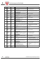
X10:1
X10:2
X10:3
X10:4
X10:5
X10:6
X10:7
TF1
DGND
DBØØ
DOØ1-C
DOØ1-NO
DOØ1-NC
DOØ2
TF/TH connection (connect to X10:2 via TF/TH), factor setting: "No response" (→ P835)
Reference potential for binary signals
Binary output 0, with fixed assignment "/Brake", load capacity max. 150 mA (short-circuit proof)
Shared contact binary output 1, factory setting: "Ready"
Normally open contact binary output 1, load capacity of the relay contacts max. 30 VDC and 0.8 A
NC contact binary output 1
Binary output 2, factory setting: /Fault", load capacity max. 50 mA (short-circuit proof)
Selection options for binary outputs 1 and 2 (DOØ1 and DOØ2) → Parameter menu P62_
Do not apply an external voltage to binary outputs X10:3 (DBØØ) and X10:7 (DOØ2)!
X10:8
X10:9
X10:10
VO24
VI24
DGND
Auxiliary supply output +24 V (max. 200 mA) for external command switches
Input +24 V voltage supply (backup voltage depending on options, unit diagnosis when supply system off)
Reference potential for binary signals
Output incremental encoder simulation or input external encoder. Only encoders
with a signal level according to RS-422 (5 V TTL) are allowed as external
encoders.
If X14: is used as an incremental encoder simulation output, X14:4 must be
jumpered with X14:5 (switchover – DGND).
Signal level of incremental encoder simulation to RS-422 (5 V TTL).
Pulse count of the incremental encoder simulation:
• With MDV60A as on X15: Motor encoder input
• With MDS60A 1024 pulses/revolution
Motor encoder input
With MDV60A
Permitted encoders:
- sin/cos enc. 1 VSS
- 5 V TTL encoder
- 24 V HTL encoder
sin+ (S2)
Resolver input
cos+ (S1)
With MDS60A
Ref.+ (R1)
Permitted resolver:
NC
2-pole, 7 VAC_rms, 7 kHz
DGND
sin- (S4)
cos- (S3)
Ref.- (R2)
TF/TH connection (connect to X15:5 via TF/TH)
TERMINAL
Option slot for DBG11A keypad or serial port USS21A (RS-232 and RS-485)
OPTION1/OPTION2
2 slots for option pcbs
MOVIDRIVE® MD_60A Operating Instructions
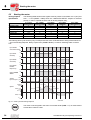
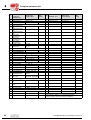
Assignment of braking resistors, chokes and filters
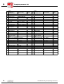
4.6
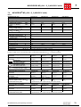
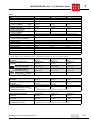
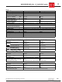
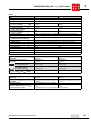
Assignment of braking resistors, chokes and filters
400/500 V units, sizes 1 and 2
MOVIDRIVE® MD_60A...-5A3
0015
0022
Size
Braking resistors
Trip current
Part number
BW100-005
IF = 0.8 ARMS
826 269 1
BW100-006
IF = 1.8 ARMS
821 701 7
BW168
IF = 2.5 ARMS
820 604 X
BW268
IF = 3.4 ARMS
820 715 1
BW147
IF = 3.5 ARMS
820 713 5
BW247
IF = 4.9 ARMS
820 714 3
BW347
IF = 7.8 ARMS
820 798 4
BW039-012
IF = 4.2 ARMS
821 689 4
BW039-026
IF = 7.8 ARMS
821 690 8
BW039-050
IF = 11 ARMS
821 691 6
Line chokes
ΣIsystem = 20 AAC
826 012 5
ND045-013
ΣIsystem = 45 AAC
826 013 3
Input filters
Vmax = 550 VAC
NF035-503
Output chokes
0055
0075
0110
2
Part number
NF009-503
NF014-503
0040
Part numbers
ND020-013
NF018-503
0030
1
827 412 6
A
827 116 X
B
A
B
827 413 4
827 128 3
Inside diameter
Part number
HD001
d = 50 mm (1.97 in)
813 325 5
For cable cross sections 1.5 – 16 mm2 (AWG 16 – 6)
HD002
d = 23 mm (0.91 in)
813 557 6
For cable cross sections ≤ 1.5 mm2 (AWG 16)
HD003
d = 88 mm (4.46 in)
813 558 4
For cable cross sections > 16 mm2 (AWG 6)
Output filters (only in VFC mode)
Part number
HF015-503
826 030 3
A
HF022-503
826 031 1
B
HF030-503
826 032 X
HF040-503
826 311 6
HF055-503
826 312 4
HF075-503
826 313 2
HF023-403
825 784 1
HF033-403
825 785 X
A
In rated operation (100 %)
B
With variable torque load in VFC mode (125 %)
MOVIDRIVE® MD_60A Operating Instructions
A
B
A
B
A
B
A
B
A
B
A
B
23
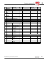
Assignment of braking resistors, chokes and filters
400/500 V units, sizes 3 to 5
MOVIDRIVE® MD_60A...-503
0150
Size
Braking resistors
0300
0370
3
0450
Part number
IF = 4.0 ARMS
821 684 3
C
C
BW018-035
IF = 8.1 ARMS
821 685 1
C
C
BW018-075
IF = 14 ARMS
821 686 X
C
C
BW915
IF = 28 ARMS
821 260 0
IF = 6.1 ARMS
821 680 0
BW012-050
IF = 12 ARMS
821 681 9
BW012-100
IF = 22 ARMS
821 682 7
BW106
IF = 38 ARMS
821 050 0
BW206
IF = 42 ARMS
821 051 9
ND045-013
ΣIsystem = 45 AAC
826 013 3
A
ND085-013
ΣIsystem = 85 AAC
826 014 1
B
ND1503
ΣIsystem = 150 AAC
825 548 2
Part numbers
Input filters
B
827 128 3
A
NF048-503
827 117 8
B
NF063-503
827 414 2
Vmax = 550 VAC
NF115-503
A
B
A
B
827 415 0
A
B
827 416 9
NF150-503
Output chokes
A
Part number
NF035-503
NF085-503
0750
5
Trip current
BW012-025
0550
4
BW018-015
Line chokes
A
B
827 417 7
Inside diameter
Part number
HD001
d = 50 mm (1.97 in)
813 325 5
For cable cross sections 1.5 – 16 mm2 (AWG 16 – 6)
HD003
d = 88 mm (4.46 in)
813 558 4
For cable cross sections > 16 mm2 (AWG 6)
Output filters (only in VFC mode)
Part number
825 785 X
A
B/D
HF047-403
825 786 8
B
A
HF450-503
826 948 3
HF033-403
24
0220
A/D
B
A
In rated operation (100 %)
B
With variable torque load in VFC mode (125 %)
C
Connect two braking resistors in parallel and set twice the trip current on F16 (2 × IF)
D
Connect two output filters in parallel
E
In rated operation (100 %): One output filter
With variable torque load (125 %): Connect two output filters in parallel
E
D
D
MOVIDRIVE® MD_60A Operating Instructions
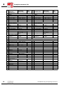
Assignment of braking resistors, chokes and filters
230 V units, sizes 1 to 4
MOVIDRIVE® MD_60A...-2_3
0015
Size
Braking resistors
0022
0037
0055
1
0075
0110
2
0150
0220
3
0300
4
Trip current
Part number
BW039-003
IF = 2.0 ARMS
821 687 8
BW039-006
IF = 3.2 ARMS
821 688 6
BW039-012
IF = 4.2 ARMS
821 689 4
BW039-026
IF = 7.8 ARMS
821 690 8
BW027-006
IF = 2.5 ARMS
822 422 6
BW027-012
IF = 4.4 ARMS
822 423 4
BW018-015
IF = 4.0 ARMS
821 684 3
C
C
C
C
BW018-035
IF = 8.1 ARMS
821 685 1
C
C
C
C
BW018-075
IF = 14 ARMS
821 686 X
C
C
C
C
BW915
IF = 28 ARMS
821 260 0
C
C
C
C
BW012-025
IF = 10 ARMS
821 680 0
BW012-050
IF = 19 ARMS
821 681 9
BW012-100
IF = 27 ARMS
821 682 7
BW106
IF = 38 ARMS
821 050 0
C
C
BW206
IF = 42 ARMS
821 051 9
C
C
Line chokes
ND020-013
Part numbers
ΣIsystem = 20 AAC
826 012 5
A
B
ND045-013
ΣIsystem = 45 AAC
826 013 3
ND085-013
ΣIsystem = 85 AAC
826 014 1
ND1503
ΣIsystem = 150
AAC
825 548 2
Input filters
B
B
827 412 6
A
NF014-503
827 116 X
B
NF018-503
827 413 4
NF048-503
A
Part number
NF009-503
NF035-503
A
Vmax = 550 VAC
A
B
827 128 3
827 117 8
A
NF063-503
827 414 2
B
NF085-503
827 415 0
A
827 416 9
B
NF115-503
Output chokes
Internal diameter
Part number
HD001
d = 50 mm
(1.97 in)
813 325 5
For cable cross sections 1.5 – 16 mm2
(AWG 16 – 6)
HD002
d = 23 mm
(0.91 in)
813 557 6
For cable cross sections ≤ 1.5 mm2
(AWG 16)
HD003
d = 88 mm
(4.46 in)
813 558 4
For cable cross sections > 16 mm2
(AWG 6)
A
In rated operation (100 %)
B
With variable torque load in VFC mode (125 %)
C
Connect two braking resistors in parallel and set twice the trip current on F16 (2 × IF)
MOVIDRIVE® MD_60A Operating Instructions
25
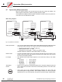
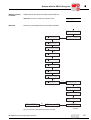
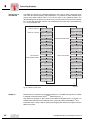
System bus (SBus) connection
4.7
System bus (SBus) connection
Max. 64 CAN bus stations can be interconnected using the system bus (SBus). The
SBus supports transmission systems compliant with ISO 11898.
The "System Bus (SBus)" manual contains detailed information about the system bus.
This manual can be obtained from SEW.
SBus wiring diagram
Control unit
Control unit
X11:
System bus
Terminating resistor
System bus
ref.potential
System bus high
System bus low
REF1
AI11
AI12
AGND
REF2
S 11
S 12
System bus
Terminating resistor
ON OFF
X12:
1
2
3
DGND
SC11
SC12
System bus
ref.potential
System bus high
System bus low
y
Control unit
X11:
1
2
3
4
5
REF1
AI11
AI12
AGND
REF2
REF1
AI11
AI12
AGND
REF2
S 11
S 12
System bus
Terminating resistor
ON OFF
X12:
DGND
SC11
SC12
X11:
1
2
3
4
5
System bus
ref.potential
System bus high
System bus low
1
2
3
y
y
1
2
3
4
5
S 11
S 12
ON OFF
X12:
DGND
SC11
SC12
1
2
3
y
02205BEN
Fig. 19: System bus connection
Cable specification
•
Use a 2-core twisted and shielded copper cable (data transmission cable with shield
comprising copper braiding). The cable must meet the following specifications:
– Conductor cross section 0.75 mm2 (AWG 18)
– Cable resistance 120 Ω at 1 MHz
– Capacitance per unit length ≤ 40 pF/m (12 pF/ft) at 1 kHz
Suitable cables are CAN bus or DeviceNet cables, for example.
Shield contact
•
Connect the shield at either end to the electronics shield clamp of the inverter or the
master control and ensure the shield is connected over a large area. Also connect
the ends of the shield to DGND.
Line length
•
The permitted total cable length depends on the baud rate setting of the SBus
(P816):
–
–
–
–
Terminating
resistor
26
125 kbaud
250 kbaud
500 kbaud
1000 kbaud
→
→
→
→
320 m (1056 ft)
160 m (528 ft)
80 m (264 ft)
40 m (132 ft)
•
Switch on the system bus terminating resistor (S12 = ON) at the beginning and end
of the system bus connection. Switch off the terminating resistor on the other units
(S12 = OFF).
•
There must not be any potential displacement between the units which are
connected together using the SBus. Take suitable measures to avoid a potential
displacement, e.g. by connecting the unit ground connectors using a separate lead.
MOVIDRIVE® MD_60A Operating Instructions
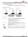
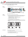
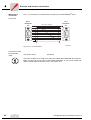
RS-485 interface connection
4.8
RS-485 interface connection
The RS-485 interface can be used for connecting max. 32 MOVIDRIVE® units, e.g. for
master/slave operation, or 31 MOVIDRIVE® units and a CAN machine control (PLC).
Wiring diagram, RS-485 interface
Control unit
Control unit
X13:
RS-485 +
RS-485 -
Control unit
X13:
DIØØ 1
DIØ1 2
DIØ2 3
DIØ3 4
DIØ4 5
DIØ5 6
DCOM 7
VO24 8
DGND 9
ST11 10
ST12 11
RS-485 +
RS-485 -
DIØØ 1
DIØ1 2
DIØ2 3
DIØ3 4
DIØ4 5
DIØ5 6
DCOM 7
VO24 8
DGND 9
ST11 10
ST12 11
X13:
RS-485 +
RS-485 -
DIØØ 1
DIØ1 2
DIØ2 3
DIØ3 4
DIØ4 5
DIØ5 6
DCOM 7
VO24 8
DGND 9
ST11 10
ST12 11
02206AEN
Fig. 20: RS-485 connection
Cable specification
•
Use a 2-core twisted and shielded copper cable (data transmission cable with shield
comprising copper braiding). The cable must meet the following specifications:
– Conductor cross section 0.5 – 0.75 mm2 (AWG 20 – 18)
– Cable resistance 100 – 150 Ω at 1 MHz
– Capacitance per unit length ≤ 40 pF/m (12 pF/ft) at 1 kHz
The following cable is suitable, for example:
– BELDEN (www.belden.com), data cable type 3105A
Shield contact
•
Connect the shield at either end to the electronics shield clamp of the inverter or the
machine control and ensure the shield is connected over a large area. Also connect
the ends of the shield to DGND.
Line length
•
The permitted total line length is 200 m (660 ft).
Terminating
resistor
•
Dynamic terminating resistors are fitted. Do not connect any external terminating
resistors!
•
There must not be any potential displacement between the units which are
connected together using the RS-485. Take suitable measures to avoid a potential
displacement, e.g. by connecting the unit ground connectors using a separate lead.
MOVIDRIVE® MD_60A Operating Instructions
27
Connection option USS21A (RS-232 and RS-485)
4.9
Connection option USS21A (RS-232 and RS-485)
Part number USS21A: 822 914 7
RS-232
connection
•
Use a shielded standard interface cable for connecting to the RS-232 interface.
USS21A
PC COM 1-4
5
GND (ground)
5
3
2
TxD
3
2
RxD
max. 5 m (16.5 ft)
9-pin sub D connector (male)
9-pin sub D connector (female)
02399AEN
Fig. 21: Connection cable USS21A – PC
RS-485
connection
Please observe the following connection instructions:
•
Use a 2-core twisted and shielded copper cable (data transmission cable with shield
comprising copper braiding). The cable must meet the following specifications:
– Conductor cross section 0.5 – 0.75 mm2 (AWG 20 – 18)
– Cable resistance 100 – 150 Ω at 1 MHz
– Capacitance per unit length ≤ 40 pF/m (12 pF/ft) at 1 kHz
The following cable is suitable, for example:
– BELDEN (www.belden.com), data cable type 3105A
•
Connect the shield at either end to the electronics shield clamp of the inverter and
ensure the shield is connected over a large area. Also connect the ends of the shield
to DGND.
USS21A
0V5 -
+
1
y
2
3
1
2
3
y
USS21A
0V5 -
+
y
y
00997CXX
Fig. 22: RS-485 interface of the USS21A
EIA standard
28
The RS-485 interface of the USS21A corresponds to the EIA standard:
•
Max. transmission rate 9600 baud
•
Max. 32 participants (each unit with USS21A counts as 2 participants)
•
Max. cable length 200 m (660 ft) in total
•
Dynamic terminating resistor with fixed installation
MOVIDRIVE® MD_60A Operating Instructions
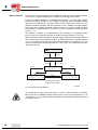
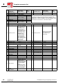
Combinations of options
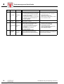
4.10 Combinations of options
The following tables show the possible combinations of options in the status as supplied.
The meaning of the individual table entries is as follows:
-
The options cannot be used in conjunction with one another.
L|R
Connect the option in the first column (↓) to the OPTION1 slot.
Connect the option in the title row (→) to the OPTION2 slot.
R|L
Connect the option in the first column (↓) to the OPTION2 slot.
Connect the option in the title row (→) to the OPTION1 slot.
CONTROL
OPTION2 (R)
OPTION1 (L)
TERMINAL
02714BXX
Fig. 23: Configuration of option slots
Combinations of options, applies to all MOVIDRIVE® units1):
MDF / MDV / MDS
DIP11A
DFP11A
DFP21A
DFI11A
DFI21A
DFC11A
DFO11A
DFD11A
DIO11A
DRS11A1)
No 2nd
option
DIP11A
-
R|L
R|L
R|L
R|L
R | L2)
R|L
R
DFP11A
DFP21A
L|R
-
-
-
-
L|R
L|R
L
DFI11A
DFI21A
L|R
-
-
-
-
L|R
L|R
L
DFC11A
DFO11A
L|R
-
-
-
-
L|R
L|R
L
DFD11A
L|R
-
-
-
-
L|R
L|R
L
↓
→
DIO11A
DRS11A
2)
L|R
L|R
R|L
R|L
R|L
R|L
R|L
R|L
R|L
R|L
L|R
3)
L|R
R|L
R
-
R
1) Exception for DRS11A: MOVIDRIVE® MDV or MDS is required for this option.
2) Only the binary terminals of the DIO11A can be set using parameters P6__. The binary terminals of the DIP11A are only available via
the IPOSplus® system variables (→ IPOS manual).
3) The "input/output card type DIO11A" option can be connected in pairs. In this case, when the DIO11A is connected to "OPTION2 (R)",
bear in mind that the analog inputs/outputs cannot be used and the binary terminals cannot be set using parameters P6__. The binary
terminals of the DIO11A on "OPTION2 (R)" are only available via the IPOSplus® system variables (→ IPOS manual).
Example
If a MOVIDRIVE® MDV or MDS is equipped with the fieldbus interface PROFIBUS type
DFP11A and synchronous operation card type DRS11A options, then the DFP11A must
be connected to the OPTION1 (L) slot and the DRS11A to the OPTION2 (R) slot.
MOVIDRIVE® MD_60A Operating Instructions
29
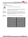
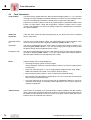
Installing and removing option pcbs
4.11
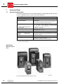
Installing and removing option pcbs
Before you begin
Installing the
option pcb
•
Take suitable measures to dissipate any electrical charge in your body before you
touch the option pcb (discharge strap, conductive shoes, etc.).
•
Keep the option pcb in its original packaging and do not remove it until just before
installing it.
•
Do not touch the option pcb more than necessary. Only hold it by the edge of the
board and do not touch any components.
•
Disconnect inverter from the supply system, switch off supply system and 24 VDC.
•
Remove the keypad, serial interface or blank panel.
•
Remove the lower hood cover from the control unit.
•
Unscrew the electronics shield clamp.
•
Use a suitable screwdriver to lever out and remove the black cover plate.
•
Insert the option pcb into the guide rails of the OPTION1 or OPTION2 slot and push
it in.
•
Apply moderate pressure to the front panel to push on the option pcb. The option pcb
has been clipped in correctly when it is flush with the control pcb.
•
Replace the electronics shield clamp and draw on retainer screws.
•
Put the hood cover of the control unit back on.
•
It may not be possible to fit the hood cover, depending on the option pcb and which
sub D connector is used. This does not impair the enclosure of the unit.
•
Put the keypad, serial interface or blank panel back on.
02025AXX
Fig. 24: Lever out the cover plate
30
MOVIDRIVE® MD_60A Operating Instructions
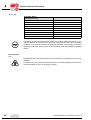
Installing and removing option pcbs
Removing the
option pcb
•
Disconnect inverter from the supply system, switch off supply system and 24 VDC.
•
Remove the keypad, serial interface or blank panel.
•
Remove the lower hood cover from the control unit.
•
Unscrew the electronics shield clamp.
•
Use a suitable screwdriver to lever out the option pcb and pull it out.
•
Insert another option pcb or a black cover plate in the place of the option pcb.
•
Replace the electronics shield clamp and draw on retainer screws.
•
Put the hood cover of the control unit back on.
•
Put the keypad, serial interface or blank panel back on.
02026AXX
Fig. 25: Lever out the option pcb
MOVIDRIVE® MD_60A Operating Instructions
31
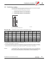
Connection and terminal description of the DIO11A option
4.12 Connection and terminal description of the DIO11A option
Part number
Terminal expansion board option type DIO11A: 822 726 8
Front view of DIO11A
Terminal
X20:1/2
DIO
X20
X21
X22
X23
1
2
3
AI21
AI22
AGND
1
2
3
4
5
6
AOV1
AOC1
AGND
AOV2
AOC2
AGND
1
2
3
4
5
6
7
8
9
10
DI1Ø
DI11
DI12
DI13
DI14
DI15
DI16
DI17
DCOM
DGND
1
2
3
4
5
6
7
8
9
DO1Ø
DO11
DO12
DO13
DO14
DO15
DO16
DO17
DGND
Voltage input
Function
AI21/22
X20:3
AGND
X21:1
X21:4
AOV1
AOV2
X21:2
X21:5
AOC1
AOC2
X21:3/6
AGND
X22:1 – 8 DI1Ø – 17
X22:9
X22:10
DCOM
DGND
X23:1 – 8 DO1Ø – 17
X23:9
DGND
Setpoint input n2, -10 V – 0 – 10 V or 0 – 10 V
(Differential input or input with AGND reference potential)
Reference potential for analog signals (REF1, REF2, AI.., AO..)
Analog voltage output V1, factory setting: actual speed
Analog voltage output V2, factory setting: output current
Load capacity of the analog voltage outputs: Imax = 10 mA
Analog current output C1, factory setting: actual speed
Analog current output C2, factory setting: output current
P642/645 "Operating mode AO1/2" sets whether the voltage outputs V1/2
(-10 V – 0 – 10 V) or the current outputs C1/2 (0(4) – 20 mA) are in effect.
Selection options for the binary outputs → Parameter menu P640/643
Max. permitted cable length: 10 m (33 ft)
Reference potential for analog signals (REF1, REF2, AI.., AO..)
Binary inputs 1 – 8, factory setting: no function
The binary inputs are electrically isolated by optocouplers.
Selection options for the binary outputs → Parameter menu P61_
Reference potential for the binary inputs DI1Ø – 17
Reference potential for binary signals
– Without jumper X22:9 – X22:10 (DCOM – DGND) → Isolated binary
inputs
– With jumper X22:9 – X22:10 (DCOM – DGND) → Non-isolated binary
inputs
Binary outputs 1 – 8, factory setting: no function
Load capacity of the binary outputs: Imax = 50 mA (short-circuit proof)
Do not apply external voltage to the binary outputs!
Reference potential for binary signals
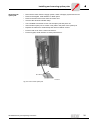
The analog setpoint input n2 (AI21/22) can be used as a differential input or as an input
with AGND reference potential.
Differential input
Input with AGND reference potential
DIO
DIO
X20
1
2
3
V
AI21
AI22
AGND
0...+10 V
-10...0...+10 V
X20
1
2
3
+
AI21
AI22
AGND
V
05202AXX
Fig. 26: Setpoint input n2
32
MOVIDRIVE® MD_60A Operating Instructions
Connection and terminal description of the DIO11A option
Current input
You must use an external load if the analog setpoint input n2 (AI21/22) should be used
as a current input.
For example RB = 500 Ω → 0 – 20 mA = 0 – 10 V
DIO
X20
500 Ω
+
-
1
2
3
0...10 V
0...20 mA
AI21
AI22
AGND
01671BXX
Fig. 27: Current input with external load
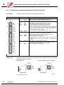
Voltage outputs
Analog voltage outputs AOV1 and AOV2 must be assigned as shown in the following
diagram:
DIO
DIO
X20
X20
1
2
3
AI21
AI22
AGND
1
2
3
4
5
6
AOV1
AOC1
AGND
AOV2
AOC2
AGND
AI21
AI22
AGND
1
2
3
4
5
6
AOV1
AOC1
AGND
AOV2
AOC2
AGND
X21
V
-10...0...10 V
-10...0...10 V
X21
1
2
3
V
05203AXX
Fig. 28: Voltage outputs AOV1 and AOV2
Current outputs
Analog current outputs AOC1 and AOC2 must be assigned as shown in the following
diagram:
DIO
DIO
X20
X20
1
2
3
AI21
AI22
AGND
1
2
3
4
5
6
AOV1
AOC1
AGND
AOV2
AOC2
AGND
X21
0(4)...20 mA
+
A
-
1
2
3
AI21
AI22
AGND
1
2
3
4
5
6
AOV1
AOC1
AGND
AOV2
AOC2
AGND
X21
0(4)...20 mA
+
A
05204AXX
Fig. 29: Current outputs AOC1 and AOC2
MOVIDRIVE® MD_60A Operating Instructions
33
Encoder and resolver connection
4.13 Encoder and resolver connection
The "SEW Encoder Systems" manual contains detailed information. This manual can be
obtained from SEW.
General
installation notes
•
Max. line length of inverter – encoder/resolver: 100 m (330 ft) with a capacitance per
unit length ≤ 120 nF/km (193 nF/mile).
•
Core cross section: 0.20 – 0.5 mm2 (AWG 24 – 20)
•
If you cut off a core of the encoder/resolver cable: Isolate the cut-off end of the core.
•
Use shielded twisted pair cables (exception: cables for HTL sensors) and connect
the shield over a wide area at both ends:
– to the encoder in the cable screw fitting or in the encoder plug
– to the inverter in the housing of the sub D plug
•
Route the encoder/resolver cable separately from the power cables.
Shield contact
Connect the shield of the encoder/resolver cable over a large area.
On the inverter
Connect the shield on the inverter end in the housing of the sub D plug.
01939BXX
Fig. 30: Connect the shield in the sub D plug
On the encoder/
resolver
Connect the shield on the encoder/resolver end in the cable screw fitting or in the
encoder plug.
01948AXX
Fig. 31: Connect the shield in the cable screw fitting of the encoder
Pre-fabricated
cables
34
•
SEW offers pre-fabricated cables for connecting encoders/resolvers. We
recommend using these pre-fabricated cables.
•
The conductor colors specified in the connection figures are in accordance with
IEC 757 and correspond to the conductor colors used in the pre-fabricated cables
from SEW.
MOVIDRIVE® MD_60A Operating Instructions
Encoder and resolver connection
Motor encoder
The following motor encoders may be connected to X15: of MOVIDRIVE® MDV60A
units:
•
High-resolution sin/cos encoders with signal voltage 1 VSS
•
5 V TTL sensors with signal level to RS-422
•
24 V HTL sensors
01936AXX
Fig. 32: Connection terminals of SEW motor encoders
Voltage supply
Encoders with 24 VDC voltage supply (max. 180 mA) are connected directly to X15:.
These encoders are then powered by the inverter.
Encoders with a 5 VDC voltage supply must be connected via the "5 V encoder power
supply type DWI11A" option (part number 822 759 4).
sin/cos encoders
High-resolution sin/cos encoders ES1S, ES2S or EV1S are recommended for operation
with MOVIDRIVE® MDV60A. These encoders are powered with 24 VDC and do not need
a sensor cable. Connect the sin/cos encoder as follows:
max. 100 m (330 ft)
ES1S / ES2S / EV1S
ES1R / ES2R / EV1R A (K1)
A (K1)
B (K2)
B (K2)
C (K0)
C (K0)
UB ⊥ K1 K2 K0 K1 K2 K0
UB ⊥ A B C A B C
UB
X15:
YE
GN
RD
BU
PK
GY
WH
BN
⊥
VT
✂
1
6
2
7
3
8
9
5
4
y
9
6
5
1
y
03021AXX
Fig. 33: Connecting the sin/cos encoder
Cut off the violet conductor (VT) of the cable at the encoder end.
Part numbers of
the pre-fabricated
cables
For fixed routing:
198 829 8
For cat track routing:
198 828 X
MOVIDRIVE® MD_60A Operating Instructions
35
Encoder and resolver connection
5 V TTL sensors
5 V TTL sensors from SEW are available with a 24 V DC voltage supply and a 5 VDC
voltage supply.
24 VDC voltage
supply
Connect 5 V TTL sensors to the 24 VDC voltage supply ES1R, ES2R or EV1S in the
same way as the high-resolution sin/cos encoders.
5 VDC voltage
supply
5 V TTL sensors with a 5 VDC voltage supply ES1T, ES2T or EV1T must be connected
via the "5 V encoder power supply type DWI11A" option (part number 822 759 4). The
sensor cable must be connected as well in order to correct the supply voltage of the
encoder. Connect these encoders as follows:
max. 5 m (16.5 ft)
5
9
6
1
DWI11A
YE
GN
RD
BU
PK
GY
WH
BN
⊥
VT
N.C.
1
6
2
7
3
8
9
5
4
A (K1)
A (K1)
B (K2)
B (K2)
C (K0)
C (K0)
UB
y
ES1T / ES2T / EV1T
UB ⊥ K1 K2 K0 K1 K2 K0
UB ⊥ A B C A B C
max. 100 m (330 ft)
6
9
1
5
y
YE
GN
RD
BU
PK
GY
WH
BN
⊥
VT*
A (K1)
A (K1)
B (K2)
B (K2)
C (K0)
C (K0)
UB
1
6
2
7
3
8
9
5
4*
y
X1: MOVIDRIVE
1
6
2
7
3
8
9
5
4
9
X2: Encoder
X15:
6
5
1
y
03023AXX
Fig. 34: Connecting TTL sensors via DWI11A
* Connect the sensor line (VT) on the encoder to UB, do not jumper on the DWI11A!
Part numbers of
the pre-fabricated
cables
36
MOVIDRIVE® X15: → DWI11A X1:MOVIDRIVE
Only fixed routing:
814 344 7
Encoder ES1T /ES2T / EV1T → DWI11A X2: encoder
For fixed routing:
198 829 8
For cat track routing:
198 828 X
MOVIDRIVE® MD_60A Operating Instructions
Encoder and resolver connection
HTL sensors
If you are using a 24 V HTL sensor ES1C, ES2C or EV1C, you are not allowed to
connect the negated channels A (K1), B (K2) and C (K0).
max. 100 m (330 ft)
ES1C / ES2C / EV1C
A (K1)
A (K1)
B (K2)
B (K2)
C (K0)
C (K0)
UB
UB ⊥ K1 K2 K0 K1 K2 K0
UB ⊥ A B C A B C
⊥
X15:
YE
GN
GY
WH
BN
y
y
1
N.C. 6
2
N.C. 7
3
N.C. 8
9
5
N.C. 4
9
6
5
1
03022AXX
Fig. 35: Connecting HTL sensors
Part numbers of
the pre-fabricated
cables
For fixed routing:
198 932 4
For cat track routing:
198 931 6
Absolute encoder
The absolute encoder AV1Y has a fixed connection cable 1 m (3.3 ft) in length with a
17-pin round connector plug suitable for the SPUC 17B FRON female connector made
by Interconnectron. The plug has the following pin assignment:
Pin
Conductor color in pre-fabricated cable
Description
6-core cable
10-core cable
Supply voltage VS
+10 – 15 – 24 – 30 VDC, polarity reversal
protected
White (WH)
White (WH)
10
Supply voltage GND
Electrically isolated from AV1Y housing
Brown (BN)
Brown (BN)
14
Serial data output D+
"1" = High signal
Yellow (YE)
Black (BK)
17
Serial data output D-
"0" = High signal
Green (GN)
Violet (VT)
8
Clock line, current loop T+
7 mA towards T+ = "1"
Pink (PK)
Pink (PK)
9
Clock line, current loop T-
7 mA towards T- = "0"
Gray (GY)
Gray (GY)
15
Incremental encoder signal A
Yellow (YE)
16
Incremental encoder signal A
Green (GN)
12
Incremental encoder signal B
13
Incremental encoder signal B
7
Connection to the
DPA11A option
1 VSS sin/cos
-
Red (RD)
Blue (BU)
Connect the absolute encoder AV1Y to the DPA11A option as follows:
max. 100 m (330 ft)
AV1Y
8
11
12 10
9
13 16
9 14
17
14 15
8 17
1
2
3
4
5
6
7
T+ PK
T- GY
32 DPA11A
X50:
33
D+ YE
D- GN
34
35
BN
10 GND
US WH
7
38
39
y
y
03977AXX
Fig. 36: Connecting AV1Y to DPA11A
MOVIDRIVE® MD_60A Operating Instructions
37
Encoder and resolver connection
Connection to the
DIP11A option
Connect the absolute encoder AV1Y to the DIP11A option as follows:
8
11
12 10
13 16
9
17
14 15
8
1
2
3
4
5
6
DIP11A
X62:
max. 100 m (330 ft)
AV1Y
9
14
17
T+ PK
T- GY
3
D+ YE
D- GN
1
8
BN
10 GND
US WH
7
7
9
5
6
5
6
1
9
y (N.C.) 2
(N.C.) 4
y
(N.C.) 7
03978AXX
Fig. 37: Connecting AV1Y to DIP11A
Connecting as a
combination
encoder
You can also use the AV1Y absolute encoder on MOVIDRIVE® MDV60A as a
combination encoder (absolute and incremental). The encoder is then connected to
X62: of the DIP11A option and X15: of the MOVIDRIVE® MDV60A basic unit.
8
11
12 10
9
13 16
9 14
17
14 15
8 17
1
2
3
4
5
6
DIP11A
X62:
max. 100 m (330 ft)
AV1Y
7
T+ PK
3
T- GY
8
D+ BK
D- VT
1
GND BN
U WH
5
YE
15 A (K1)
GN
16 A (K1)
RD
12 B (K2)
BU
13 B (K2)
y (N.C.) 2
(N.C.) 4
10
7
9
5
6
6
1
9
S
(N.C.) 7
®
MOVIDRIVE
X15:
1
y
6
2
7
9
y (N.C.) 3
(N.C.) 4
6
5
1
(N.C.) 5
(N.C.) 8
(N.C.) 9
03979AXX
Fig. 38: Connecting as a combination encoder
Part numbers of
the pre-fabricated
cables
Encoder AV1Y→ DPA11A X50: (Fig. 137)
For fixed routing:
198 887 5
For cat track routing:
198 888 3
Encoder AV1Y→ DIP11A X62: (Fig. 138)
For fixed routing:
198 929 4
For cat track routing:
198 930 8
Encoder AV1Y as combination encoder → DIP11A X62: & MOVIDRIVE® X15: (Fig. 139)
38
For fixed routing:
198 890 5
For cat track routing:
198 891 3
MOVIDRIVE® MD_60A Operating Instructions
Encoder and resolver connection
Resolver
SEW offers the following pre-fabricated cables for connecting resolvers to
MOVIDRIVE® MDS60A:
Part number
For motor type
Fixed routing
CM71 – 112
DFS56
DFY71 – 112
Terminal/pin
assignment
Cat track routing
with pl. connection
199 214 7
199 215 5
with terminal box
198 829 8
198 828 X
with pl. connection
198 927 8
198 928 6
with terminal box
198 829 8
198 828 X
with pl. connection
198 827 1
198 812 3
CM motors: The resolver connections are housed in a plug connection.
DS/DY motors: Depending on the motor type, the resolver connections in the terminal
box are either accommodated on a 10-pin Phoenix terminal strip or in the plug
connection.
Plug connection CM, DS56:
Intercontec, type ASTA021NN00 10 000 5 000
Plug connection DY71 – 112:
Framatome Souriou, type GN-DMS2-12S
Terminal/pin
Description
1
Ref.+
2
Ref.-
3
cos+
4
cos-
5
sin+
6
sin-
9
TF/TH
10
TF/TH
Conductor color in pre-fabricated cable
Reference
Cosine signal
Sine signal
Motor protection
Pink (PK)
Gray (GY)
Red (RD)
Blue (BU)
Yellow (YE)
Green (GN)
White (WH)
Brown (BN)
The resolver signals have the same numbering on the 10-pin Phoenix terminal strip and
in the plug connections.
Connection
Connect the resolver as follows:
CM, DFS56,
DFY71...112
9
1
8
12 7
2 10
11
3
4
1)
6
5
MOVIDRIVE
X15:
max. 100 m (330 ft)
PK
GY
RD
BU
YE
GN
1 Ref.+
2 Ref.3 cos+
4
cos5
sin+
6
sin7
N.C.
8
N.C.
9 TF/TH WH
10 TF/TH BN
VT
2)
3
8
2
7
1
6
9
5
4
✂
y
9
6
®
5
1
y
01414BXX
Fig. 39: Connecting the resolver
1) Plug connection
2) Terminal strip
If using the pre-fabricated cable with conductor end sleeves, cut off the violet conductor
(VT) of the cable in the motor terminal box.
MOVIDRIVE® MD_60A Operating Instructions
39
Encoder and resolver connection
External
encoders
Only encoders with a signal level according to RS-422 (5 V-TTL) are allowed to be
connected to X14: of MOVIDRIVE® MDV/MDS units.
Voltage supply
Encoders with 24 VDC voltage supply (max. 180 mA) are connected directly to X14:.
These encoders are then powered by the inverter.
Encoders with a 5 VDC voltage supply must be connected via the "5 V encoder power
supply type DWI11A" option (part number 822 759 4).
Connection
External encoder with 24 VDC voltage supply:
max. 100 m (330 ft)
ES1R / ES2R / EV1R
UB ⊥ K1 K2 K0 K1 K2 K0
UB ⊥ A B C A B C
MOVIDRIVE
X14:
1
6
2
1
7 6
3
8 9
5
9
5
4
YE
GN
RD
BU
PK
GY
WH
BN
⊥
VT
A (K1)
A (K1)
B (K2)
B (K2)
C (K0)
C (K0)
UB
✂
y
®
y
03776AXX
Fig. 40: External encoder direct to X14:
Cut off the violet conductor (VT) of the cable at the encoder end.
External encoder with 5 VDC voltage supply:
max. 5 m (16.5 ft)
®
⊥
N.C.
y
ES1T / ES2T / EV1T
UB ⊥ K1 K2 K0 K1 K2 K0
UB ⊥ A B C A B C
max. 100 m (330 ft)
6
9
1
5
y
YE
GN
RD
BU
PK
GY
WH
BN
⊥
VT*
A (K1)
A (K1)
B (K2)
B (K2)
C (K0)
C (K0)
UB
1
6
2
7
3
8
9
5
4*
y
X1: MOVIDRIVE
DWI11A
1
6
2
7
3
8
9
5
4
A (K1)
A (K1)
B (K2)
B (K2)
C (K0)
C (K0)
UB
9
X2: Encoder
MOVIDRIVE
X14:
1
6
2
7
1
6
3
8
9
5
9
5
4
6
5
1
y
03777AXX
Fig. 41: Connect via DWI11A
* Connect the sensor line (VT) on the encoder to UB, do not jumper on the DWI11A!
40
MOVIDRIVE® MD_60A Operating Instructions
Encoder and resolver connection
Part numbers of
the pre-fabricated
cables
Incremental
encoder
simulation
Connection
Encoder ES1R / ES2R EV1R → MOVIDRIVE® X14: (Fig. 141)
Only fixed routing:
815 354 X
Encoder ES1T /ES2T / EV1T → DWI11A X2: encoder (Fig. 142)
For fixed routing:
198 829 8
For cat track routing:
198 828 X
You can also use X14: as an incremental encoder simulation output. To do this, you
must jumper X14:4 with X14:5 (switchover – DGND). X14: the supplies incremental
encoder signals with a signal level according to RS-422 (5 V TTL). The number of pulses
is as follows:
•
With MDV60A as on X15: Motor encoder input
•
With MDS60A 1024 pulses/revolution
Connect the evaluation for the incremental encoder simulation as follows:
®
max. 100 m (330 ft)
YE
GN
RD
BU
PK
GY
WH
BN
⊥
Umschaltung VT*
A (K1)
A (K1)
B (K2)
B (K2)
C (K0)
C (K0)
UB
MOVIDRIVE compa
X14
1
6
2
7
3
8
9
5
4
815 354 X
y
6
9
1
5
y
03818AXX
Fig. 42: Connection of incremental encoder simulation
Part number of the
pre-fabricated
cable
Only fixed routing:
MOVIDRIVE® MD_60A Operating Instructions
815 354 X
41
Encoder and resolver connection
Master/slave
connection
X14 – X14 connection (= master/slave connection) of two MOVIDRIVE® units.
Connection
Master
Slave
®
®
MOVIDRIVE
X14:
6
9
1
5
MOVIDRIVE
X14:
max. 100 m (330 ft)
1
6
2
7
3
8
9
5
4
1
6
2
7
3
8
9
5
4
y
6
9
1
5
y
05036AXX
Fig. 43: X14 – X14 connection
Part number of the
pre-fabricated
cable
Only fixed routing:
815 355 8
The sub D sockets on the ends of the cable are marked with "MASTER" and "SLAVE".
Make sure that you connect the socket marked "MASTER" to X14: of the master unit
and the socket marked "SLAVE" to X14: of the slave unit.
42
MOVIDRIVE® MD_60A Operating Instructions
General startup instructions
I
0
5
Startup
5.1
General startup instructions
It is essential to comply with the safety notes during startup!
Requirements
Correct project planning of the drive is the pre-requisite for successful startup. Refer to
the MOVIDRIVE® system manual for detailed project planning instructions and an
explanation of the parameters (chapters 4 and 5).
VFC operating
modes without
speed control
MOVIDRIVE® MD_60A drive inverters are factory set for operation with the SEW motor
(MD_60A...-5_3: 4-pole and rated voltage 3 × 400 VAC / 50 Hz or MD_60A...-2_3: 4-pole
and rated voltage 3 × 230 VAC / 60 Hz) which has been adjusted to the correct power
level. The motor can be connected and the drive started immediately in accordance with
Sec. "Starting the motor" (→ page 277).
Inverter/motor
combinations
The following tables indicate which inverter/motor combinations this applies to.
400/500 V units
MOVIDRIVE® MDF60A
or MDV60A in VFC mode
SEW motor
0015-5A3-4
DT90L4
0022-5A3-4
DV100LS4
0030-5A3-4
DV100L4
0040-5A3-4
DV112M4
0055-5A3-4
DV132S4
0075-5A3-4
DV132M4
0110-5A3-4
DV160M4
0150-503-4
DV160L4
0220-503-4
DV180L4
0300-503-4
DV200L4
0370-503-4
DV225S4
0450-503-4
DV225M4
0550-503-4
D250M4
0750-503-4
D280S4
MOVIDRIVE® MD_60A Operating Instructions
43
I
General startup instructions
0
230 V units
MOVIDRIVE® MDF60A
or MDV60A in VFC mode
SEW motor
0015-2A3-4
DT90L4
0022-2A3-4
DV100LS4
0037-2A3-4
DV100L4
0055-2A3-4
DV132S4
0075-2A3-4
DV132M4
0110-203-4
DV160M4
0150-203-4
DV180M4
0220-203-4
DV180L4
0300-203-4
DV225S4
The startup functions described in this section are used for setting the inverter so it is
optimally adapted to the motor which is actually connected and to the given boundary
conditions. It is essential to perform a startup as described in this section for the VFC
operating modes with speed control, all CFC operating modes and SERVO operating
modes.
Hoist applications
MOVIDRIVE® MD_60A drive inverters must not be used as a safety device in hoist applications.
To ensure safety, you must use monitoring systems or mechanical safety devices to prevent the possibility of injury or damage to property.
44
MOVIDRIVE® MD_60A Operating Instructions
Preliminary work and resources
I
0
5.2
Preliminary work and resources
•
Check installation.
•
Take suitable measures to prevent the motor starting up inadvertently, for example
by removing the electronics terminal block X13:. Furthermore, additional safety
precautions must be taken depending on the application in order to avoid
endangering people and machinery.
•
For startup with the DBG11A keypad:
Connect the DBG11A keypad to the TERMINAL option slot.
•
For startup with a PC and MOVITOOLS:
Connect the USS21A option to the TERMINAL option slot and use an interface cable
(RS-232) to connect it to the PC. MOVIDRIVE® and the PC must be de-energized
when you do this, otherwise undefined states may be adopted. Then switch on both
units. Install MOVITOOLS on the PC if you have not already done so. Start the
program.
•
Switch on the power system and, if necessary, the 24 V supply.
If you are using the DBG11A keypad, the following message appears for about 13 s:
SELFTEST
MOVIDRIVE
•
Undertake the correct preliminary parameter setting (e.g. factory setting).
•
Check the terminal assignment which has been set (→ P60_ / P61_).
Startup automatically changes a group of parameter values. The parameter
description P700 "Operating modes" explains which parameters are affected by this.
Refer to the MOVIDRIVE® system manual, Sec. 4 "Parameters", for the parameter
description.
MOVIDRIVE® MD_60A Operating Instructions
45
I
Startup with the DBG11A keypad
0
5.3
Startup with the DBG11A keypad
General
information
Startup with the DBG11A keypad is only possible with MDF and MDV in VFC
operating modes. Startup in CFC and SERVO operating modes is only possible using
the MOVITOOLS software.
Data required
The following data are required for successful startup:
•
Motor type (SEW motor or non-SEW motor)
•
Motor data
– Rated voltage and rated frequency.
– In addition, with a non-SEW motor: Rated current, rated power, power factor cosϕ
and rated speed.
•
Power supply voltage
The following information is also required for the startup of the speed controller:
•
Incremental encoder type
•
Encoder type and resolution of the incremental encoder:
SEW encoder type
Startup parameters
Encoder type
Encoder resolution
ES1S, ES2S, EV1
SINE ENCODER
1024
AV1Y
SINE ENCODER
512
ES1R, ES2R, EV1R
ES1T1), ES2T1), EV1T1)
INCREM. TTL SENSOR
1024
ES1C, ES2C, EV1C
INCREM. HTL SENSOR
1024
1) 5 V TTL sensors ES1T, ES2T and EV1T must be connected via the DWI11A option (→ Sec. Installation).
•
Motor data
– SEW motor: Brake yes or no and flywheel fan (Z fan) yes or no
– Non-SEW motor: Mass moment of inertia [10-4kgm2] of the motor, brake and fan
•
Rigidity of the closed-loop control system (factory setting = 1; applies to most
applications)
If the drive is tending to oscillate → setting < 1
If the transient recovery time is too long → setting > 1
Recommended setting range: 0.90 – 1 – 1.10
•
Mass moment of inertia [10-4kgm2] of the load (gear unit + driven machine)
extrapolated for the motor shaft.
•
Time for the shortest required ramp.
If you are using a TTL encoder (encoder type INCREM. TTL SENSOR) or a sin/cos
encoder (encoder type SINE ENCODER):
•
Activate encoder monitoring (P504 = "ON") after completing the startup. The function
and voltage supply of the encoder are then monitored.
Important: Encoder monitoring is not a safety function!
46
MOVIDRIVE® MD_60A Operating Instructions
I
Startup with the DBG11A keypad
0
Startup functions
of the DBG11A
Detailed description of the keypad → Sec. "Operating displays":
E
Q
01406AXX
Language change
on DBG11A
keypad
← and → at
the same
time
Commence startup.
↑
key
Next menu command or increase value in edit mode.
↓
key
Previous menu command or decrease value in edit
mode.
→ key
One menu level down or activate edit mode for the
menu command.
← key
One menu level up or deactivate edit mode for the
menu command.
Q
key
Cancel startup and return to main display.
E
key
Cancel startup and return to main display.
•
The main display of the keypad is in German.
REGLERSPERRE
STROM:
•
Press the ↓ key twice to display parameter group 8...
8..
GERAETEFUNKTIONEN
•
Press the → key twice and the ↑ key once to display
parameter 801 "Language". Press the → key to activate edit
mode. Press the ↓ or ↑ key to select the language you want
and then press the ← key to exit edit mode.
801
DEUTSCH
SPRACHE
•
Press the Q key to return to the main display.
MOVIDRIVE® MD_60A Operating Instructions
0
A
47
I
Startup with the DBG11A keypad
0
Structure of the
startup menu
CONTR. INHIBIT
CURR.:
0
A
[←] and [→]
simultaneously
STARTUP ->
IPOS_VARIABLES <-
[→]
PREPARE FOR
STARTUP
ca. 3 s
C00* PARAM. SET 1
STARTUP
[↑]
C01*
OPER. MODE 1
VFC1
[→]
[←]
C01*
_
OPER. MODE 1
VFC1
[↑] [↓]
[↑]
C02*
DV112M4
MOTOR TYPE 1
[↑]
C03*
400 V
MOT. RATED VOLT. 1
[↑]
C04*
50 HZ
MOT. RATED FREQ. 1
[↑]
C05*
400 V
MAINS RAT. VOLT. 1
[↑]
835*
NO RESPONSE
RESP. TF-SIGNAL
[↑]
C06*
CALCULATION
NO
[→]
C06*
CALCULATION
_
NO
[↑] [↓]
C06*
_
CALCULATION
C08*
SAVE
YES
_
NO
[↑] [↓]
C08*
SAVE
_
YES
COPYING
DATA ...
CONTR. INHIBIT
CURR.:
0
[Q]
A
[E]
C08*
SAVE
_
NO
02400AEN
Fig. 44: Structure of the startup menu
48
MOVIDRIVE® MD_60A Operating Instructions
Startup with the DBG11A keypad
I
0
Startup
procedure
1. "0" signal at terminal X13:1 (DIØØ "/CONTROL.INHIBIT"), e.g.
by disconnecting the electronics terminal block X13.
2. Activate the startup menu by pressing the ← and → keys on
the DBG11A at the same time.
3. Press the → key to commence the startup. The first window of
the startup menu appears. The menu commands are identified
by an * in the 4th position. Menu commands which only appear
in the startup menu start with "C", the other menu commands
have the number in the parameter list (page 280). Press the ↑
key to jump to the next menu command when you have worked
through a menu command.
CONTROL.INHIBIT
CURRENT:
0
A
STARTUP →
IPOS_VARIABLES ←
STARTUP IS
BEING PREPARED
4. Select a parameter set, e.g. parameter set 1.
C00* PARAM. SET 1
STARTUP
5. Set the operating mode, e.g. VFC1.
C01*
OPER. MODE 1
6. Select the connected motor. If a 2 or 4-pole SEW motor is
connected, select the correct motor from the list. In the case of
a non-SEW motor or an SEW motor with more than four poles,
choose "NON-SEW MOTOR" in the selection list.
C02*
DV112M4
MOT. TYPE 1
7. Refer to the nameplate of the motor and enter the rated motor
voltage for the selected connection type.
C03*
400
V
RATED MOT. VOLT. 1
VFC1
C02*
NON-SEW
MOTOR
MOT. TYPE 1
Example: Nameplate 230∆/400W 50 Hz
W connection → Enter 400 V.
∆ connection, transition point at 50 Hz → Enter 230 V.
∆connection, transition point at 87 Hz → Also enter 230 V. After
startup, first set parameter P302 "MAXIMUM SPEED 1" to the
value for 87 Hz and then start the drive.
Example: Nameplate 400∆/690W 50 Hz
Only ∆ connection possible → Enter 400 V.
W connection is not possible.
8. Enter the rated frequency specified on the motor nameplate.
Example: 230∆/400W 50 Hz
Enter 50 Hz in a W and ∆ connection.
C04*
50
Hz
RATED MOT. FREQ. 1
WITH SEW MOTORS
9. The motor values are stored for SEW 2 and 4-pole motors and
do not have to be entered.
WITH NON-SEW MOTORS
9. Enter the following data from the motor nameplate:
• Rated motor current, note the connection type ( W or ∆).
• Rated power of the motor
• Power factor cos ϕ
• Rated speed of the motor
10. Enter the rated voltage of the supply system
MOVIDRIVE® MD_60A Operating Instructions
C05*
400
V
RATED SYS. VOLT. 1
49
I
Startup with the DBG11A keypad
0
11. If no TF/TH is connected to X10:1 and X10:2 → Set "NO
RESP.". Set the required fault response if a TF/TH is
connected.
835* NO RESP.
RESP. TF sens SIGNAL
12. Commence the startup calculation by selecting "YES".
C06*
NO
CALCULATION
WITH SEW MOTORS
13. The calculation is performed.
WITH NON-SEW MOTORS
13. The calculation for non-SEW motors requires a calibration
procedure:
• When prompted, give a "1" signal on terminal X13:1 (DIØØ
"/CONTROL.INHIBIT").
• Give a "0" signal on terminal X13:1 again after the
calibration is complete.
• The motor parameters are estimated if it is not possible to
calibrate (energize) the motor.
14. The "SAVE" menu command appears automatically. The
keypad is already in edit mode.
15. Set "SAVE" to "YES". The data (motor parameters) are copied
into the non-volatile memory of MOVIDRIVE®.
16. This completes the startup. Press the E or Q key to exit the
startup menu. The main display then appears.
50
C08*
SAVE
_NO
DATA ARE BEING
COPIED...
CONTROL.INHIBIT
CURRENT:
0
A
•
Copy the parameter set from MOVIDRIVE® into the DBG11A keypad after
completing the startup (P807 "MDX → DBG"). In this way, it is possible to use the
DBG11A to transfer the parameter set to other MOVIDRIVE® units (P 806 "DBG →
MDX").
•
Enter any parameter settings which differ from the factory settings in the parameter
list (→ page 280).
•
In the case of non-SEW motors, set the correct brake reaction time (P732 / P735).
•
Refer to the information in Sec. "Starting the motor" (→ page 277) for starting the
motor.
•
With ∆ connection and transition point at 87 Hz → Set parameter P302/312
"Maximum speed 1/2" to the value for 87 Hz.
MOVIDRIVE® MD_60A Operating Instructions
I
Startup with the DBG11A keypad
0
Startup of speed
controller
Startup without the speed controller is performed first.
Important: Set VFC-n-CONTROL operating mode.
Structure
C01* VFC-n-CTRL
OPER. MODE 1
Structure of the startup menu for the speed controller:
C09*
_
NO
COMISS. N-CTLR.?
[↑] [↓]
C09*
_ YES
COMISS. N-CTLR.?
C00*
n-CONTROL
COMMISSIONING
[↑]
C15* INCREM. TTL
ENCODER TYPE
[−]
C16*
1024 inc
ENC. PULSE COUNT
[↑]
C17*
BRAKE
WITH
[↑]
C18*
STIFFNESS
1
[↑]
C19*
Z FAN
WITHOUT
[↑]
C20*
INERTIA
209.5
[↑]
C21*
SHORTEST
0
s
RAMP
[↑]
C06*
CALCULATION
NO
[→]
[←]
C06*
_
CALCULATION
NO
[↑] [↓]
C06*
_
YES
CALCULATION
C08*
SAVE
_
NO
[↑] [↓]
C08*
SAVE
CONTR. INHIBIT
CURR.:
0
A
[E]
[Q]
C08*
SAVE
_
NO
_
YES
COPYING
DATA ...
03025AEN
Fig. 45: Structure of startup with the speed controller
MOVIDRIVE® MD_60A Operating Instructions
51
I
Startup with the DBG11A keypad
0
Startup
procedure
1. Press "YES" to commence the speed controller startup. All mass moments of inertia must be
entered in the unit [10-4 kgm2].
2. Press the ↑ key to move on to the next menu item each time.
3. Enter the correct encoder type.
4. Enter the correct encoder resolution.
WITH SEW MOTORS
5. Enter whether the motor has a brake.
6. Set the rigidty of the closed-loop control system.
7. Enter whether the motor has a flywheel fan (Z fan).
WITH NON-SEW MOTORS
5. Enter the moment of inertia of the motor.
6. Set the rigidity of the closed-loop control system.
7. Set the moment of inertia of the brake and the fan.
8. Enter the mass moment of inertia of the load (gear unit + driven machine) extrapolated for
the motor shaft.
9. Enter the time for the shortest ramp.
10. Commence the speed controller startup calculation by selecting "YES".
11. The "SAVE" menu command appears automatically. Set "SAVE" to "YES". The data are
copied into the non-volatile memory of MOVIDRIVE®.
12. The "SAVE" menu command appears again. Press the E or Q key to exit the startup menu.
The main display then appears.
52
•
Copy the parameter set from MOVIDRIVE® into the DBG11A keypad after
completing the startup (P807 "MDX → DBG"). In this way, it is possible to use the
DBG11A to transfer the parameter set to other MOVIDRIVE® units (P 806 "DBG →
MDX").
•
Enter any parameter settings which differ from the factory settings in the parameter
list (→ page 280).
•
In the case of non-SEW motors, set the correct brake reaction time (P732 / P735).
•
Refer to the information in Sec. "Starting the motor" (→ page 277) for starting the
motor.
•
With ∆ connection and transition point at 87 Hz → Set parameter P302/312
"Maximum speed 1/2" to the value for 87 Hz.
•
Activate encoder monitoring for TTL sensors and sin/cos encoders (P504 = "ON").
MOVIDRIVE® MD_60A Operating Instructions
Startup with a PC and MOVITOOLS
I
0
5.4
Startup with a PC and MOVITOOLS
General
information
•
Terminal X13:1 (DIØØ "/CONTROL.INHIBIT") must get a "0" signal!
•
Start the MOVITOOLS program.
•
Set the language.
•
Select the PC port (PC COM) to which the inverter is connected.
•
Select <Update> to display the connected inverter.
05032AEN
Fig. 46: MOVITOOLS startup window
Commencing
startup
•
Click on <Shell> in "Execute Program". The Shell program is started.
•
Select the [Startup] / [Startup...] menu command. MOVITOOLS opens the startup
menu.
•
Select asynchronous or synchronous as the motor type.
•
Select parameter set 1 or 2. With speed-controlled drives, the speed controller can
be selected separately when startup is repeated. When startup is repeated, the
startup functions of the DIP11A absolute encoder interface, if installed, can also be
selected separately.
•
Set the operating mode.
•
Select an SEW motor (2 or 4-pole) or a non-SEW motor. SEW motors with more than
four poles are set as non-SEW motors.
•
Enter the motor type data and, if speed control is being used, the speed controller
data as well.
•
Press <Finish> to complete the startup.
•
Make any necessary parameter settings using the main menu or the user menu.
•
Save the parameter set. The parameter set can be transferred to other MOVIDRIVE®
units.
•
Print out the set parameters using [File] / [Print Data].
•
Refer to the information in Sec. "Starting the motor" (→ page 277) for starting the
motor.
MOVIDRIVE® MD_60A Operating Instructions
53
I
Starting the motor
0
5.5
Starting the motor
Analog setpoint
specification
The following table shows which signals must be present on terminals X11:2 (AI1) and
X13:1 – X13:4 (DIØØ – DIØ3) when the "UNIPOL/FIX.SETPT" setpoint is selected
(P100), in order to operate the drive with an analog setpoint entry.
X11:2 (AI11)
Analog input n1
X13:1 (DIØØ)
/Controller inhibit
X13:2 (DIØ1)
CW/STOP
X13:3 (DIØ2)
CCW/STOP
Controller inhibit
X
"0"
X
X
X
Rapid stop
X
"1"
X
X
"0"
Function
Enable and stop
X13:4 (DIØ3)
Enable/rapid stop
X
"1"
"0"
"0"
"1"
Clockwise at 50 % nmax
5V
"1"
"1"
"0"
"1"
Clockwise at nmax
10 V
"1"
"1"
"0"
"1"
C-clockw. at 50 % nmax
5V
"1"
"0"
"1"
"1"
Counterclockw. at nmax
10 V
"1"
"0"
"1"
"1"
The following travel cycle shows by way of example how the motor is started with the wiring of terminals X13:1
– X13:4 and analog setpoints. Binary output X10:3 (DBØØ "/Brake") is used for switching brake contactor
K12.
"1"
Input DIØØ
/Controller inhibit
"0"
"1"
Input DIØ1
CW/stop
"0"
"1"
Input DIØ2
CCW/stop
"0"
"1"
Input DIØ3
Enable/
Rapid stop
"0"
Output DBØØ
/Brake
"1"
"0"
10V
Analog
input n1 (AI11) 5V
0V
Speed
n [rpm]
nmax
50% nmax
nmin
nstart-stop
0
t11 CW up
t11 CW down
t11 CW up
t11 CW up
t11 CW down
t13 stop ramp
t11 CCW up
-50% nmax
-nmax
05033AEN
Fig. 47: Travel cycle with analog setpoints
The motor is not energized in the event of controller inhibit (DIØØ = "0"). A motor without
a brake then coasts to a halt.
54
MOVIDRIVE® MD_60A Operating Instructions
I
Starting the motor
0
Fixed setpoints
The following table shows which signals must be present on terminals X13:1 – X13:6
(DIØØ – DIØ5) when the "UNIPOL/FIX.SETPT" setpoint is selected (P100), in order to
operate the drive with the fixed setpoints.
X13:1 (DIØØ)
/Ctrler inhibit
X13:2 (DIØ1)
CW/STOP
X13:3 (DIØ2)
CCW/STOP
Controller inhibit
"0"
X
X
X
X
X
Rapid stop
"1"
X
X
"0"
X
X
Enable and stop
"1"
"0"
"0"
"1"
X
X
Clockwise at n11
"1"
"1"
"0"
"1"
"1"
"0"
Clockwise at n12
"1"
"1"
"0"
"1"
"0"
"1"
Clockwise at n13
"1"
"1"
"0"
"1"
"1"
"1"
C-clockw. at n11
"1"
"0"
"1"
"1"
"1"
"0"
Function
X13:4 (DIØ3)
Enable/rapid stop
X13:5 (DIØ4)
n11/n21
X13:6 (DIØ5)
n12/n22
The following travel cycle shows by way of example how the drive is started with the wiring of terminals X13:1
– X13:6 and the internal fixed setpoints. Binary output X10:3 (DBØØ "/Brake") is used for switching brake
contactor K12.
"1"
Input DIØØ
/Controller inhibit
"0"
"1"
Input DIØ1
CW/stop
"0"
"1"
Input DIØ2
CCW/stop
"0"
"1"
Input DIØ3
Enable/
Rapid stop
"0"
"1"
Input DIØ4
n11/n21
"0"
"1"
Input DIØ5
n12/n22
"0"
Output DBØØ
/Brake
"1"
"0"
Speed
n [rpm]
n13
t11 CW up
t11 CW up
n12
n11
0
-n11
t11 CW down
t11 CW up
-n12
t11 CCW up
t13 stop ramp
-n13
05034AEN
Fig. 48: Travel cycle with internal fixed setpoints
The motor is not energized in the event of controller inhibit (DIØØ = "0"). A motor without
a brake then coasts to a halt.
MOVIDRIVE® MD_60A Operating Instructions
55
I
Starting the motor
0
Manual operation
The inverter can be controlled using the DBG11A keypad using the manual operation
function. The 7-segment display on the unit shows "H" during manual mode.
In order for manual operation to be started, there must be a "0" signal sent to binary
inputs X13:2 (DIØ1) "CW/stop", X13:3 (DIØ2 "CCW/stop") and X13:4 (DIØ3 "Enable/
rapid stop"), if programmed. The binary inputs are then without any functions for the
duration of manual operation, with the exception of X13:1 (DIØØ "/Controller inhibit").
Binary input X13:1 (DIØØ "/Controller inhibit") must get a "1" signal to enable the drive
to be started in manual operation. The drive can also be stopped in manual operation
by X13:1 = "0".
The direction of rotation is not determined by the "CW/stop" or "CCW/stop" binary
inputs. Instead, you select the direction of rotation using the keypad (→ Fig. 150).
Manual operation remains active even after the supply system power has been switched
off/on. The inverter is then inhibited, however. A change of direction command using the
→ or ← key produces an enable and a start in the selected sense of rotation at nmin. The
speed is increased and decreased using the ↑ and ↓ keys. The modification speed is
150 rpm per second.
880
MANUAL
OFF
OPERATION
→-key
←-key
880
MANUAL
_OFF
OPERATION
↑- or ↓-key
E-key
_ DIR. OF ROTATION
L
<E>=EXIT
R
Q-key
←-key
_ 0%In
<Q>=STOP
Q-key
→-key
→-key
0 rpm
R
_ 0%In
L
←-key
0 rpm
<Q>=STOP
↑-key: increase speed
↓-key: decrease speed
02406AEN
Fig. 49: Manual mode with DBG11A
The signals at the binary inputs take effect as soon as manual operation is finished.
Binary input X13:1 (DIØØ) /Controller inhibit does not have to be switched from "1" to
"0" and back to "1". The drive can start according to the signals at the binary inputs and
the setpoint sources.
56
MOVIDRIVE® MD_60A Operating Instructions
Complete parameter list
I
0
5.6
Complete parameter list
The parameters of the short menu are identified by a "/" (= displayed on the DBG11A keypad).
Par.
Name
Value range
DISPLAY VALUES
Par.
Name
06_
Binary outputs option
00_
Process values
000
Speed
001/
User display
[Text]
062
Binary output DO12
002
Frequency
0 – 400 Hz
063
Binary output DO13
003
Actual position
0 – 231-1 inc
064
Binary output DO14
004
Output current
0 – 200 % IN
065
Binary output DO15
005
Active current
-200 – 0 – 200 % IN
066
Binary output DO16
006/
Motor utilization 1
0 – 200 %
067
Binary output DO17
007
Motor utilization 2
0 – 200 %
068/
Status binary outputs option
008
DC link voltage
0 – 1000 V
07_
Unit data
009
Output current
A
070
Unit type
01_
Status displays
071
Unit rated current
010
Inverter status
072
Option 1
011
Operational status
073
Option 2
012
Fault status
074
Firmware option 1
013
Active parameter set
1/2
075
Firmware option 2
014
Heat sink temperature
-20 – 0 – 100 °C
076
Firmware basic unit
015
Mains ON operation time
0 – 25000 h
077
Technology function
016
Operating time (enabled)
0 – 25000 h
08_
Fault memory
017
Electrical energy
kWh
080/
Fault t-0
02_
Analog setpoints
081
Fault t-1
020
Analog input AI1
-10 – 0 – 10 V
082
Fault t-2
021
Analog input AI2
-10 – 0 – 10 V
083
Fault t-3
022
External current limit
0 – 100 %
084
Fault t-4
03_
Binary inputs basic unit
09_
Bus diagnosis
030
Binary input DIØØ
090
PD configuration
031
Binary input DIØ1
091
Fieldbus type
032
Binary input DIØ2
092
Fieldbus baud rate
033
Binary input DIØ3
093
Fieldbus address
034
Binary input DIØ4
094
PO1 setpoint
035
Binary input DIØ5
095
PO2 setpoint
036/
Status binary inputs basic unit
096
PO3 setpoint
04_
Binary inputs option
097
PI1 actual value
040
Binary input DI1Ø
098
PI2 actual value
041
Binary input DI11
099
PI3 actual value
042
Binary input DI12
043
Binary input DI13
044
Binary input DI14
045
Binary input DI15
046
Binary input DI16
047
Binary input DI17
048/
Status binary inputs option
05_
Binary outputs basic unit
050
Binary output DBØØ
051
Binary output DOØ1
-5000 – 0 – 5000 rpm
/CONTROL.INHIBIT
060
Binary output DO1Ø
061
Binary output DO11
Value range
/BRAKE
052
Binary output DOØ2
053/
Status binary outputs basic unit
MOVIDRIVE® MD_60A Operating Instructions
57
I
Complete parameter list
0
Name
Par. Variable par.
Parameter set 1
Setting range
Factory setting
1__
SETPOINTS / RAMP GENERATORS
10_
Setpoint selection
100/ Setpoint source
UNIPOL/FIX.SETPT
101
Control signal source
TERMINALS
11_
Analog input AI1
110
AI1 scaling
-10 – -0.1 / 0.1 – 1 – 10
111
AI1 offset
-500 – 0 – 500 mV
112
AI1 operation mode
Ref. N-MAX
113
AI1 voltage offset
-10 – 0 – 10 V
114
AI1 speed offset
-5000 – 0 – 5000 rpm
115
Filter setpoint
0 – 5 – 100 ms 0 = Filter
off
12_
Analog inputs (optional)
120
AI2 operation mode
13_
Speed ramps 1
130/ Ramp t11 UP CW
After
startup
Parameter set 2
Setting range
Factory setting
14_ Speed ramps 2
0 – 2 – 2000 s
140 Ramp t21 UP CW
0 – 2 – 2000 s
141 Ramp t21 DOWN CW 0 – 2 – 2000 s
132/ Ramp t11 UP CCW
0 – 2 – 2000 s
142 Ramp t21 UP CCW
0 – 2 – 2000 s
0 – 2 – 2000 s
Ramp t21 DOWN
143
CCW
0 – 2 – 2000 s
134/ Ramp t12 UP=DOWN 0 – 2 – 2000 s
135
S pattern t12
After
startup
NO FUNCTION
131/ Ramp t11 DOWN CW 0 – 2 – 2000 s
Ramp t11 DOWN
133/
CCW
58
Name
Par.
144 Ramp t22 UP=DOWN 0 – 2 – 2000 s
0–3
145 S pattern t22
0–3
136/ Stop ramp t13
0 – 2 – 20 s
146 Stop ramp t23
0 – 2 – 20 s
137/ Emergency ramp t14
0 – 2 – 20 s
147 Emergency ramp t24
0 – 2 – 20 s
15_
Motorized potentiometer (parameter set 1 and 2)
150
Ramp t3 UP
151
Ramp t3 DOWN
0.2 – 20 – 50 s
152
Save last setpoint
ON / OFF
16_
Fixed setpoints 1
0.2 – 20 – 50 s
17_ Fixed setpoints 2
160/ Internal setpoint n11
-5000 – 0 – 150 – 5000
rpm
170 Internal setpoint n21
-5000 – 0 – 150 – 5000
rpm
161/ Internal setpoint n12
-5000 – 0 – 750 – 5000
rpm
171 Internal setpoint n22
-5000 – 0 – 750 – 5000
rpm
162/ Internal setpoint n13
-5000 – 0 – 1500 – 5000
rpm
172 Internal setpoint n23
-5000 – 0 – 1500 – 5000
rpm
MOVIDRIVE® MD_60A Operating Instructions
I
Complete parameter list
0
Name
Par. Variable par.
Parameter set 1
Setting range
Factory setting
2__
CONTROLLER PARAMETERS
20_
Speed control (only parameter set 1)
200
P gain speed controller 0.1 – 2 – 32
201
Time constant ncontrol.
0 – 10 – 300 ms
202
Gain accel.
feedforward
0 – 32
203
Filter accel.
feedforward
0 – 100 ms
204
Filter speed actual
value
0 – 32 ms
205
Load feedforward
0 – 150 %
206
Sample time n-control. 1 ms = 0 / 0.5 ms = 1
207
Load feedforward VFC 0 – 150 %
21_
Hold controller
210
P gain hold controller
22_
Synchr. oper. control (only parameter set 1)
220
P-gain (DRS)
1 – 10 – 200
221
Master gear ratio
factor
1 – 3,999,999,999
222
Slave gear ratio factor 1 – 3,999,999,999
223
Mode selection
Mode 1 Mode 2 Mode 3
Mode 4 Mode 5 Mode 6
Mode 7 Mode 8
224
Slave counter
-99,999,999 – -10 / 10 –
99,999,999 inc
225
Offset 1
-32767 – -10 /
10 – 32767 inc
226
Offset 2
-32767 – -10 /
10 – 32767 inc
227
Offset 3
-32767 – -10 /
10 – 32767 inc
228
Feedforward filter
(DRS)
0 – 100 ms
23_
Synchr. oper. w. sync. encoder
230
Synchronous encoder
OFF / EQUALRANKING / CHAIN
231
Factor slave encoder
1 – 1000
232
Factor slave sync.
encoder
1 – 1000
24_
Synchr. oper. w. catch up
240
Synchronization speed
241
Synchronization ramp 0 – 2 – 50 s
After
startup
Name
Par.
Parameter set 2
Setting range
Factory setting
After
startup
0.1 – 2 – 32
Only with MOVITOOLS. Not visible on the DBG11A keypad.
-5000 – 0 – 1500 –
5000 rpm
MOVIDRIVE® MD_60A Operating Instructions
59
I
Complete parameter list
0
Name
Par. Variable par.
Parameter set 1
3__
MOTOR PARAMETERS
30_
Limits 1
After
startup
Name
Par.
Parameter set 2
Setting range
Factory setting
After
startup
31_ Limits 2
300/ Start/stop speed 1
0 – 60 – 150 rpm
310 Start/stop speed 2
0 – 60 – 150 rpm
301/ Minimum speed 1
0 – 60 – 5500 rpm
311 Minimum speed 2
0 – 60 – 5500 rpm
302/ Maximum speed 1
0 – 1500 – 5500 rpm
312 Maximum speed 2
0 – 1500 – 5500 rpm
303/ Current limit 1
0 – 150%IN
313 Current limit 2
0 – 150%IN
304
Torque limit
0 – 150 %
32_
Motor compensat. 1 (asynchr.)
Automatic adjustment
320/
1
60
Setting range
Factory setting
ON / OFF
33_ Motor compensat. 2 (asynchr.)
330
Automatic adjustment
ON / OFF
2
321
Boost 1
0 – 100 %
331 Boost 2
0 – 100 %
322
IxR compensation 1
0 – 100 %
332 IxR compensation 2
0 – 100 %
323
Premagnetizing time 1 0 – 0.1 – 2 s
333 Premagnetizing time 2 0 – 0.1 – 2 s
324
Slip compensation 1
0 – 500 rpm
334 Slip compensation 2
34_
Motor protection
340
Motor protection 1
ON / OFF
342 Motor protection 2
ON / OFF
341
Cooling type 1
FAN COOLED / forcedcooling
343 Cooling type 2
FAN-COOLED / forcedcooling
35_
Motor sense of rotation
350
Change direction
of rotation 1
ON / OFF
351
360
Startup
YES / NO
Only available in DBG11A, not in MOVITOOLS/SHELL!
4__
REFERENCE SIGNALS
40_
Speed reference signal
400
Speed reference value 0 – 1500 – 5000 rpm
401
Hysteresis
402
Delay time
0–1–9s
403
Signal = "1" if:
n < nref / n > nref
41_
Speed window signal
410
Window center
0 – 1500 – 5000 rpm
411
Range width
0 – 5000 rpm
Change direction
of rotation 2
0 – 500 rpm
ON / OFF
0 – 100 – 500 rpm
412
Delay time
0–1–9s
413
Signal = "1" if:
INSIDE / OUTSIDE
42_
Speed setp./act. val. comp.
420
Hysteresis
421
Delay time
0–1–9s
422
Signal = "1" if:
n <> nsetpt / n = nsetpt
43_
Current reference signal
430
Current reference
value
0 – 100 – 150 % IN
431
Hysteresis
0 – 5 – 30 % IN
432
Delay time
0–1–9s
433
Signal = "1" if:
I<Iref / I>Iref
44_
Imax signal
440
Hysteresis
441
Delay time
0–1–9s
442
Signal = "1" if:
I = Imax / I < Imax
1 – 100 – 300 rpm
0 – 5 – 50 % IN
MOVIDRIVE® MD_60A Operating Instructions
Complete parameter list
I
0
Name
Par. Variable par.
Parameter set 1
Setting range
Factory setting
5__
MONITORING FUNCTIONS
50_
Speed monitoring
500
Speed
monitoring 1
501
504
51_
Synchr. operation monitoring
510
Positioning tol. slave
10 – 25 – 32768 inc
511
Prewarning lag error
50 – 99,999,999 inc
512
Lag error limit
100 – 4000 –
99,999,999 inc
513
Delay lag error
message
0 – 1 – 99 s
514
Counter
LED display
10 – 100 – 32768 inc
After
startup
Name
Par.
Parameter set 2
OFF / MOTOR MODE /
REGENERAT. MODE /
MOT.& REGEN.MODE
502
Delay time 1
0 – 1 – 10 s
503 Delay time 2
Encoder monitoring
ON / OFF
515
Delay in-position signal 5 – 10 – 2000 ms
52_
Mains OFF monitoring
520
Mains OFF response
time
0–5s
521
Mains OFF response
CONTROL.INHIBIT
EMERGENCY STOP
6__
TERMINAL ASSIGNMENT
60_
Binary inputs basic unit
-
Binary input DIØØ
Speed
monitoring 2
Setting range
Factory setting
After
startup
OFF / MOTOR MODE /
REGENERAT. MODE /
MOT.& REGEN.MODE
0 – 1 – 10 s
With fixed assignment: /
CONTROL.INHIBIT
600
Binary input DIØ1
CW/STOP
601
Binary input DIØ2
CCW/STOP
602
Binary input DIØ3
ENABLE/RAP.STOP
603
Binary input DIØ4
n11/n21
604
Binary input DIØ5
n12/n22
61_
Binary inputs option
610
Binary input DI1Ø
NO FUNCTION
611
Binary input DI11
NO FUNCTION
612
Binary input DI12
NO FUNCTION
613
Binary input DI13
NO FUNCTION
614
Binary input DI14
NO FUNCTION
615
Binary input DI15
NO FUNCTION
616
Binary input DI16
NO FUNCTION
617
Binary input DI17
NO FUNCTION
62_
Binary outputs basic unit
-
Binary output DBØØ
With fixed assignment: /BRAKE
620
Binary output DOØ1
READY
621
Binary output DOØ2
/FAULT
63_
Binary outputs option
630
Binary output DO1Ø
NO FUNCTION
631
Binary output DO11
NO FUNCTION
632
Binary output DO12
NO FUNCTION
633
Binary output DO13
NO FUNCTION
634
Binary output DO14
NO FUNCTION
635
Binary output DO15
NO FUNCTION
636
Binary output DO16
NO FUNCTION
637
Binary output DO17
NO FUNCTION
MOVIDRIVE® MD_60A Operating Instructions
The following functions can be programmed: NO FUNCTION•
ENABLE/RAP.STOP • CW/STOP •CCW/STOP • n11(n13) •
n21(n23) • n12(n13) • n22(n23) •FIX SETPT SW.OV. • PAR.
SWITCHOVER •RAMP SWITCHOVER • MOTOR POT UP •
MOTOR POT DOWN • /EXT. FAULT • FAULT RESET • /HOLD
CONTROL • /LIM. SWITCH CW • /LIM. SWITCH CCW • IPOS
INPUT •REFERENCE CAM • REF. TRAVEL START •SLAVE
FREE RUNN. • SETPOINT HOLD • MAINS ON •DRS SET ZERO
PT. • DRS SLAVE START • DRS TEACH IN •DRS
MAST.STOPPED
The following signals can be programmed: NO FUNCTION • /
FAULT • READY • OUTP. STAGE ON • ROT. FIELD ON • BRAKE
RELEASED • BRAKE APPLIED • MOTOR STANDSTILL •
PARAMETER SET • SPEED REFERENCE • SPEED WINDOW •
SP/ACT.VAL.COMP. • CURR. REFERENCE • Imax-SIGNAL • /
MOTOR UTILIZ.1 • /MOTOR UTILIZ.2 • DRS PREWARN. • /DRS
LAG ERROR • DRS SLAVE IN POS • IPOS IN POSITION • IPOS
REFERENCE • IPOS OUTPUT • /IPOS FAULT
61
I
Complete parameter list
0
Name
Par. Variable par.
Parameter set 1
64_
62
Setting range
Factory setting
After
startup
Name
Par.
Parameter set 2
Setting range
Factory setting
After
startup
Analog outputs optional
640
Analog output AO1
ACTUAL SPEED
641
Scaling AO1
-10 – 0 – 1 – 10
642
Operating mode A01
OFF / -10 – +10V / 0 –
20mA / 4 – 20mA
643
Analog output AO2
OUTP.CURRENT
644
Scaling AO2
-10 – 0 – 1 – 10
645
Operating mode AO2
OFF / -10 – +10V / 0 –
20mA / 4 – 20mA
7__
CONTROL FUNCTIONS
70_
Operating Modes
The following functions can be programmed: NO FUNCTION •
RAMP INPUT • SPEED SETPOINT • ACTUAL SPEED • ACTUAL
FREQUENCY • OUTPUT CURRENT • ACTIVE CURRENT • UNIT
UTILIZATION • IPOS OUTPUT • RELATED TORQUE
VFC 1 VFC 1 & GROUP
VFC 1 & HOIST VFC 1
& DC BRAK. VFC 1
&FLY.START VFC-nCONTROL VFC-nCTRL.&GROUP VFC-nCTRL&HOIST VFC-nCTRL& SYNC VFC-nCTRL& IPOS VFC-nCTRL&DPx CFC
CFC&M-CONTROL
CFC& IPOS CFC&
SYNC. CFC& DPx
SERVO SERVO & MCTRL. SERVO & IPOS
SERVO & SYNC.
SERVO & DPx
701 Operating mode 2
VFC 2 VFC 2 & GROUP
VFC 2 & HOIST VFC 2
& DC BRAK. VFC 2
&FLY.START
0 – 50 % IMot
711 Standstill current 2
0 – 50 % IMot
700
Operating mode 1
71_
Current at standstill
710
Standstill current 1
72_
Setpoint stop function
720
Setpoint stop function
1
ON / OFF
723
721
Stop setpoint 1
0 – 30 – 500 rpm
724 Stop setpoint 2
0 – 30 – 500 rpm
722
Start offset 1
0 – 30 – 500 rpm
725 Start offset 2
0 – 30 – 500 rpm
73_
Brake function
730
Brake function 1
ON / OFF
733 Brake function 2
ON / OFF
731
Brake release time 1
0–2s
734 Brake release time 2
0–2s
732
Brake application time
0 – 0.2 – 2 s
1
74_
Speed skip
Setpoint stop function
ON / OFF
2
Brake application time
735
0 – 0.2 – 2 s
2
740
Skip window center 1
0 – 1500 – 5000 rpm
742 Skip window center 2
0 – 1500 – 5000 rpm
741
Skip width 1
0 – 300 rpm
743 Skip width 2
0 – 300 rpm
75_
Master-Slave function
750
Slave setpoint
MASTER-SLAVE OFF
SPEED (RS-485)
SPEED (SBus) SPEED
(485+SBus) TORQUE
(RS-485) TORQUE
(SBus)
TORQUE(485+SBus)
LOAD SHAR(RS-485)
LOAD SHARE (SBus)
LOAD S(485+SBus)
751
Scaling
Slave setpoint
-10 – 0 – 1 – 10
MOVIDRIVE® MD_60A Operating Instructions
Complete parameter list
I
0
Name
Par. Variable par.
Parameter set 1
8__
UNIT FUNCTIONS
80_
Setup
Setting range
Factory setting
802/ Factory setting
YES / NO
803/ Parameter lock
ON / OFF
804
NO FAULT MEMORY
KWH-METER
OPERATING HOURS
Reset statistic data
800/ Quick menu
801/ Language
Name
Par.
Parameter set 2
Setting range
Factory setting
After
startup
ON / OFF
DE / EN / FR
Copy DBG → MDX
YES / NO
807
Copy MDX → DBG
YES / NO
81_
Serial communication
806
After
startup
810
RS485 address
811
RS-485 group address 100 – 199
These parameters are only available in the DBG11A keypad, not in
MOVITOOLS!
0 – 99
812
RS485 timeout delay
813
SBus address
0 – 650 s
0 – 63
814
SBus group address
0 – 63
815
SBus timeout delay
0 – 0.1 – 650 s
816
SBus baud rate
125/250/500 / 1000
kbaud
817
SBus synchronization
ID
0 – 1023
818
CAN synchronization
ID
0 – 1 – 2047
819
Fieldbus timeout delay 0 – 0.5 – 650 s
82_
Brake operation
820/
4-quadrant
operation 1
83_
Fault response
830
response
EXT. FAULT
831
Response
RAPID STOP/WARNG
FIELDBUS TIMEOUT
832
Response
MOTOR OVERLOAD
EMERG.STOP/FAULT
833
Response
RS485 TIMEOUT
RAPID STOP/WARNG
834
Response DRS LAG
ERROR
EMERG.STOP/FAULT
835/
Response
TF sensor SIGNAL
NO RESPONSE
836
Response
SBus TIMEOUT
EMERG.STOP/FAULT
84_
Reset response
ON / OFF
821
4-quadrant
operation 2
ON / OFF
EMERG.STOP/FAULT
840/ Manual reset
YES / NO
841
Auto reset
ON / OFF
842
Restart time
1 – 3 – 30 s
85_
Scaling speed actual value
850
Scaling factor
numerator
1 – 65535
851
Scaling factor
denominator
1 – 65535
852
User dimension
1 rpm
MOVIDRIVE® MD_60A Operating Instructions
The following fault responses can be programmed: NO
RESPONSE • DISPLAY FAULT • IMM. STOP/FAULT •
EMERG.STOP/FAULT • RAPID STOP./FAULT • IMM. STOP/
WARNG • EMERG. STOP/WARNG • RAPID STOP/WARNG
Can only be set using MOVITOOLS
63
I
Complete parameter list
0
Name
Par. Variable par.
Parameter set 1
64
Setting range
Factory setting
After
startup
Name
Par.
Parameter set 2
Setting range
Factory setting
86_
Modulation
860
PWM frequency 1
4/8/12/16 kHz
861 PWM frequency 2
4/8/12/16 kHz
862
PWM fix 1
ON / OFF
863 PWM fix 2
ON / OFF
87_
Process data description
870
Setpoint description
PO1
CTRL. WORD 1
871
Setpoint description
PO2
SPEED
872
Setpoint description
PO3
NO FUNCTION
873
Actual value
description PI1
STATUS WORD1
874
Actual value
description PI2
SPEED
875
Actual value
description PI3
OUTP.CURRENT
876
PO data enable
ON / OFF
877
DeviceNet PD
configuration
1 – 24 PD / PARAM + 1
– 24 PD
88_
Manual operation
880
Manual operation
9__
IPOS PARAMETERS
90_
IPOS Reference travel
After
startup
ON / OFF
900
Reference offset
-231 – 0 – 231-1 inc
901
Reference speed 1
0 – 200 – 5000 rpm
902
Reference speed 2
0 – 50 – 5000 rpm
903
Reference travel type
0–7
91_
IPOS Travel parameter
910
Gain X controller
0.1 – 0.5 – 32
911
Positioning ramp 1
0 – 1 – 20 s
912
Positioning ramp 2
0 – 1 – 20 s
913
Travel speed CW
0 – 1500 – 5000 rpm
914
Travel speed CCW
0 – 1500 – 5000 rpm
915
Speed feedforward
-199.99 – 0 – 100 –
199.99 %
916
Ramp type
LINEAR / SINE /
SQUARED / BUSRAMP
92_
IPOS Monitoring
920
SW limit switch
CW
-231 – 0 – 231-1 inc
921
SW limit switch
CCW
-231 – 0 – 231-1 inc
922
Position window
0 – 50 – 32767 inc
923
Lag error window
0 – 5000 – 231-1 inc
93_
IPOS Special functions
930
Override
ON / OFF
931
CTRL word task 1
START / STOP
Only available in DBG11A, not in MOVITOOLS/SHELL!
932
CTRL word task 2
START / STOP
Only available in DBG11A, not in MOVITOOLS/SHELL!
Display parameter, cannot be edited using DBG11A.
MOVIDRIVE® MD_60A Operating Instructions
I
Complete parameter list
0
Name
Par. Variable par.
Parameter set 1
Setting range
Factory setting
94_
IPOS Variables/Encoder
940
IPOS variables edit
941
MOTOR ENC. (X15)
Source actual position EXTERN.ENC (X14)
ABSOL.ENC. (DIP)
942
Encoder factor
numerator
1 – 32767
943
Encoder factor
denominator
1 – 32767
944
Encoder scaling ext.
encoder
x1/x2/x4/x8/x16/x32/x64
95_
DIP
950
Encoder type
NO ENCODER
951
Counting direction
NORMAL/INVERTED
952
Cycle frequency
1 – 200 %
953
Position offset
-(231-1) – 0 – 231-1
954
Zero offset
-(231-1) – 0 – 231-1
955
Encoder scaling
x1/x2/x4/x8/x16/x32/x64
96_
IPOS Modulo Function
960
Modulo function
ON / OFF
After
startup
Name
Par.
Parameter set 2
Setting range
Factory setting
After
startup
This parameter is only available in the DBG11A keypad, not in
MOVITOOLS!
Only with MOVITOOLS. Not visible on the DBG11A keypad.
OFF / SHORT /
CW / CCW
961
Modulo numerator
0 – 231
962
Modulo denominator
0 – 231
963
Modulo encoder
resolution
0 – 4096 – 20000
MOVIDRIVE® MD_60A Operating Instructions
65
Operating displays
6
Operation and Servicing
6.1
Operating displays
7-segment
display
DBG11A keypad
The 7-segment display shows the operating status of MOVIDRIVE® in hexadecimal
notation and, in the event of a fault, a fault or warning code.
Display
Meaning
0
Inverter not ready
1
Controller inhibit active
2
No enable
3
Current at standstill
4
VFC mode
5
n-control
6
M-control
7
Hold control
8
Factory setting
9
Limit switch reached
A
Technology option
b
Free
C
IPOS reference travel
d
Flying start
E
Free
F
Fault display (flashing) → page 294
H
Manual operation
t
Timeout active → page 293
Basic displays:
CONTROL.INHIBIT
CURRENT:
0
A
Display when X13:1 (DIØØ "/CONTROL.INHIBIT") = "0".
NO ENABLE
CURRENT:
Display when X13:1 (DIØØ "/CONTROL.INHIBIT") = "1" and
inverter is not enabled ("ENABLE/RAPID STOP" = "0").
SPEED
CURRENT:
66
0
A
942 rpm
2.51 A
Display when inverter enabled.
NOTE XX
XXXXXXXXXXXXXXXXXXX
Information message
FAULT
XX
XXXXXXXXXXXXXXXXXXX
Fault indication
MOVIDRIVE® MD_60A Operating Instructions
Operating displays
Copy function of
the DBG11A
The DBG11A keypad can be used for copying complete parameter sets from one
MOVIDRIVE® unit to another MOVIDRIVE®. To do this, copy the parameter set onto the
keypad using P807 (MD_ → DBG). Connect the keypad to another MOVIDRIVE® unit
and copy the parameter set onto the MOVIDRIVE® using P 806 (DBG → MD_). The
keypad can be disconnected and plugged in during operation.
The COMMUNIC. ERROR NO SERIAL LINK fault message appears on the display if no
communication can be established with the inverter after the supply system or the 24 V
power supply is switched on and the DBG11A is connected. Try to establish the
connection by connecting the DBG11A again.
Selected via menu
1st Menu level
Main menu
2nd Menu level
Submenu
3rd Menu level
Parameters
Editing mode
[↑] [↓]
CONTR. INHIBIT
CURR.:
0 A
0.. DISPLAY
VALUES
1.. SETPOINTS/
RAMP GENERATORS [→]
[←]
3.. MOTOR
PARAMETERS
[↑] [↓]
10. SETPOINT
SELECTION
4.. REFERENCE
SIGNALS
11. ANALOG INP. 1
[→]
(+/- 10 V)
5.. MONITORING
FUNCTIONS
12. ANALOG
INPUT AI2
6.. TERMINAL
ASSIGNMENT
13. SPEED
RAMPS 1
7.. CONTROL
FUNCTIONS
14. SPEED
RAMPS 2
8.. UNIT
FUNCTIONS
15. MOTOR. POT.
9.. IPOS
PARAMETERS
16. FIXED
SETPOINTS 1
17. FIXED
SETPOINTS 2
[←]
[↑] [↓]
110
A11
1
SCALING
0 mV [→] 111
OFFSET [←] A11
111
A11
112
A11
REF. NMAX
OPERAT. MODE
113
A11
0 V
V-OFFSET
114
A11
0 /M
n-OFFSET
0 mV
OFFSET
115
1.89 ms
SETPOINT FILTER
02407AEN
Fig. 50: Menu structure
E
Q
01406AXX
← or →
key
Change menu level, in 3rd menu level (parameter) entry to (→) or exit from (←) edit
mode. The parameter can only be changed in edit mode. Startup is commenced if
the ← and → keys are pressed at the same time (→ Sec. "Startup").
↑ or ↓
key
Select menu command, increase or decrease value in edit mode. The new value
comes into effect in edit mode when the ↑ or ↓ key is released.
Q
key
Back to main display; in startup mode, cancel startup.
E
key
Startup:
Cancel startup
Normal operation:
Signature display; the signature can only be entered or edited
with MOVITOOLS/SHELL and is used for identifying the
parameter set or the unit.
Manual mode:
Exit manual mode
Malfunction:
Call up reset parameter P840
MOVIDRIVE® MD_60A Operating Instructions
67
Operating displays
Quick menu of
the DBG11A
The DBG11A keypad has a detailed parameter menu and a clearly structured quick
menu with the most frequently used parameters. It is possible to switch between both
menus using P800 ("Quick menu"). This can be done in any operating status. The
default setting is for the quick menu to be active. The quick menu is shown on the display
by a "/" after the parameter number. The parameters in the quick menu are identified by
a "/" in the parameter list.
[↓] [↑]
BASIC DISPLAY
DISPLAY VALUES
150 rpm
SP N11
161/
INTERNAL
750 rpm
SP N12
162/
INTERNAL
1500 rpm
SP N13
300/
ST/STOP
0
rpm
SPEED 1
048/
00000000
INPUT DI1:01234567
301/
MINIMUM
0
rpm
SPEED 1
053/
001
OUT. TERM.DOØ: 012
302/
MAXIMUM
1500 rpm
SPEED 1
068/
00000000
OUTP. D1: 01234567
303/
150
CURRENT LIMIT
080/
FAULT
NO FAULT
320/
ON
AUTOMAT. ADJUST. 1
942 rpm
2.51 A
001/
USER
006/
MOTOR
0
[rpm
]
0
%
1
UTIL.
036/
INPUT DIO:
SETPOINTS /
RAMP GENERATORS
[↓] [↑]
160/
INTERNAL
SPEED:
CURR.:
000000
012345
t-Ø
100/
UNIPOL./FIX
SETPOINTS SOURCE
2
CW
MOTOR PARAMETERS
800/
SHORT MENU
ON
801/
LANGUAGE
ENGLISH
802/
FACTORY
NO
SETTING
130/
T11
UP
131/
T11
2
s
DOWN CW
132/
T11
UP
133/
T11
2
s
DOWN CCW
820/
4-QUADR-OPER.
134/
T12
10
UP=DOWN
835/
RESP.
2
CCW
s
UNIT FUNCTIONS
s
s
136/
2
s
RAP. STP. RAMP T13
137/
EMERG.
2
RAMP
%
1
803/
PARAMETER
840/
MANUAL
OFF
LOCK
ON
1
NO RESPONSE
TF-SIGNAL
NO
RESET
s
T14
[↓] [↑]
[↓] [↑]
02408AEN
Fig. 51: DBG11A quick menu
IPOSplus®
MOVITOOLS is required for programming IPOSplus®. The DBG11A keypad only makes
it possible to edit and modify IPOSplus® parameters (P9__).
The IPOSplus® program is also stored in the DBG11A keypad when it is saved. It is
transferred as well when the parameter set is copied to another MOVIDRIVE® unit.
Parameter P931 can be used for starting and stopping the IPOSplus® program from the
DBG11A keypad.
68
MOVIDRIVE® MD_60A Operating Instructions
Operating displays
Information
messages
Information messages on the DBG11A (approx. 2 s in duration) or in MOVITOOLS/
SHELL (message which can be acknowledged):
No.
Text DBG11A/SHELL
Description
1
ILLEGAL INDEX
Index addressed via interface is not available.
2
NOT IMPLEMENTED
•
•
•
3
READ ONLY VALUE
Attempt to edit a read only value.
4
PARAM. LOCKED
Parameter lock P803 = "ON". Parameter cannot be altered.
5
SETUP ACTIVE
Attempt to alter parameters during active factory setting.
6
VALUE TOO LARGE
Attempt to enter a value which is too large.
7
VALUE TOO SMALL
Attempt to enter a value which is too small.
8
REQ. PCB MISSING
The option pcb required for the selected function is missing.
10
ONLY VIA ST1
Manual mode must be completed using X13:ST11/ST12 (RS-485).
11
TERMINAL ONLY
Manual mode must be completed using TERMINAL (DBG11A or
USS21A).
12
NO ACCESS
Access to selected parameter refused.
13
NO CTRLER. INHIBIT
Set terminal DIØØ "/Controller inhibit" = "0" for the selected function.
14
INVALID VALUE
Attempt to enter an invalid value.
PARAM. NOT SAVED
EEPROM buffer overrun, e.g. due to cyclical write accesses. Parameter is
saved in EEPROM and is not protected against loss following POWER
OFF.
Attempt to execute a non-implemented function.
An incorrect communication service has been selected.
Manual mode selected via impermissible interface (e.g. fieldbus).
-
-16
MOVIDRIVE® MD_60A Operating Instructions
69
Fault information
6.2
Fault information
Fault memory
The fault memory (P080) stores the last five fault messages (faults t-0 – t-4). The fault
message of longest standing is deleted whenever more than five fault messages have
occurred. The following information is stored when a malfunction takes place:
Fault which occurred • Status of the binary inputs/outputs • Operational status of the
inverter • Inverter status • Heat sink temperature • Speed • Output current • Active
current • Unit utilization • DC link circuit voltage • ON hours • Enable hours • Parameter
set • Motor utilization.
Switch-off
responses
There are three switch-off responses depending on the fault; the inverter is inhibited
when in fault status:
Immediate switchoff
The unit can no longer brake the drive; the output stage goes to high resistance in the
event of a fault and the brake is applied immediately (DBØØ "/Brake" = "0").
Rapid stop
The drive is braked with the stop ramp t13/t23. Once the stop speed is reached, the
brake is applied (DBØØ "/Brake" = "0"). The output stage goes to high-resistance after
the brake reaction time has elapsed (P732 / P735).
Emergency stop
The drive is braked with the emergency ramp t14/t24. Once the stop speed is reached,
the brake is applied (DBØØ "/Brake" = "0"). The output stage goes to high-resistance
after the brake reaction time has elapsed (P732 / P735).
Reset
A fault message can be acknowledged by:
•
Switching the supply system off and on again.
Recommendation: Observe a minimum switch-off time of 10 s for the supply system
contactor K11.
Timeout active
70
•
Reset via input terminals, i.e. via an appropriately assigned binary input (DIØ1 –
DIØ5 with the basic unit, DI1Ø – DI17 with the DIO11A option).
•
Manual reset in SHELL (P840 = "YES" or [Parameter] / [Manual reset]).
•
Manual reset using the DBG11A (pressing the <E> key in the event of a fault gives
direct access to parameter P840).
•
Auto reset performs up to five unit resets with an adjustable restart time. Not to be
used with drives where an automatic restart represents a risk of injury to people or
damage to equipment.
If the inverter is controlled via a communications interface (fieldbus, RS-485 or SBus)
and the power was switched off and back on again or a fault reset was performed, then
the enable remains ineffective until the inverter once again receives valid data via the
interface which is monitored with a timeout.
MOVIDRIVE® MD_60A Operating Instructions
Fault messages and list of faults
6.3
Fault messages and list of faults
Fault message on
7-segment
display
The fault or warning code is displayed in BCD format. The following display sequence
is adhered to (e.g. fault code 84):
Flashes, approx. 1 s
Display off, approx. 0.2 s
Tens, approx. 1 s
Display off, approx. 0.2 s
Ones, approx. 1 s
Display off, approx. 0.2 s
01038AXX
The display switches over to the operating display following a reset or if the fault or
warning code once more resumes the value "0".
List of faults
A dot in the "P" column means that the response is programmable (P83_ Fault
response). The factory set fault response is listed in the "Response" column.
Fault
code
Description
Reaction
00
No fault
-
01
Over-current
Immediate
shut-off
03
Ground fault
P Possible cause
Short circuit on output
Motor too large
Defective output stage
•
•
•
Rectify the short circuit
Connect a smaller motor
Contact SEW Service for advice if the
output stage is defective
Immediate
shut-off
Ground fault
• in the connecting harness
• in the inverter
• in the motor
•
•
Eliminate ground fault
Contact SEW Service for advice
•
•
•
•
•
•
•
•
•
Extend deceleration ramps
Check feeder to braking resistor
Check technical data of braking resistor
Fit a new MOVIDRIVE® if the brake
chopper is defective
•
•
Extend deceleration ramps
Check connecting harness for braking
resistor
Check technical data of braking resistor
04
Brake chopper
Immediate
switch-off
07
DC link
overvoltage
Immediate
switch-off
•
•
•
Measure
Regenerative power excessive
Braking resistor circuit interrupted
Short circuit in braking resistor circuit
Excessively high braking resistance
Brake chopper defective
DC link voltage too high
•
MOVIDRIVE® MD_60A Operating Instructions
71
Fault messages and list of faults
Fault
code
Description
Reaction
P Possible cause
•
08
n-monitoring
Immediate
switch-off
•
•
09
Startup
Immediate
switch-off
Measure
Speed controller or current controller (in
VFC operating mode without encoder)
operating at setting limit due to
mechanical overload or phase fault in the
power system or motor
Encoder not connected correctly or
incorrect direction of rotation
nmax is exceeded during torque control
•
•
•
•
•
•
•
•
Inverter startup not yet performed for selected Perform startup for appropriate operating
operating mode.
mode.
•
•
10
IPOS-ILLOP
Emergency
stop
•
Incorrect command detected during
running of IPOS program.
Incorrect conditions during command
execution.
•
•
Check program memory content and
correct if necessary.
Load correct program into program
memory.
Check program sequence (→ IPOS
manual)
11
Excessive
temperature
Emergency
stop
Thermal overload of inverter.
Reduce load and/or ensure adequate cooling.
12
Resolver
14 bits
Emergency
stop
Only with MDS:
14-bit resolver evaluation is active and the
actual speed is greater than or equal to 3600
rpm.
Set P302 "Maximum speed 1" to max. 3000
rpm.
13
Control signal Immediate
source
switch-off
Control signal source not defined or defined
incorrectly.
Set correct control signal source (P101).
14
Encoder
Immediate
switch-off
15
24 V internal
Immediate
switch-off
No internal 24 V supply voltage.
17-24
System fault
Immediate
switch-off
Check ground connections and shields;
Inverter electronics disrupted, possibly due to
improve them if necessary. Contact SEW
effect of EMC.
Service for advice if this reoccurs.
25
EEPROM
Rapid stop
Fault when accessing EEPROM
26
External
terminal
Emergency
stop
27
Limit switches Emergency
missing
stop
28
Fieldbus
timeout
29
30
•
31
•
•
•
Encoder cable or shield not connected
correctly
Check encoder cable and shield for correct
Short circuit/open circuit in encoder cable connection, short circuit and open circuit.
Encoder defective
Check the mains connection. Contact SEW
Service for advice if this reoccurs.
Call up default setting, perform reset and set
parameters again. Contact SEW Service for
advice if this reoccurs.
Read in external fault signal via programmable Eliminate specific cause of fault; reprogram
input.
terminal if appropriate.
Open circuit/both limit switches missing
Limit switches are swapped over in
relation to direction of rotation of motor
•
•
•
Check wiring of limit switches
Swap over limit switch connections
Reprogram terminals
Rapid stop
No master-slave communication took place
• within the configured response monitoring
period.
•
•
Check master communication routine
Extend fieldbus timeout time (P819) or
switch off monitoring
Limit switch
reached
Emergency
stop
Limit switch was reached in IPOS operating
mode.
•
•
Check travel range
Correct user program.
Emergency
stop
timeout
Immediate
switch-off
•
•
Drive overloaded
Emergency stop ramp too short
•
•
Check project planning
Extend emergency stop ramp
•
•
Motor too hot, TF sensor has tripped
TF sensor of motor not connected or not
connected properly
MOVIDRIVE® connection and TF
connection on motor interrupted
No link between X10:1 and X10:2. With
MDS: X15:9 – X15:5 connection missing.
•
•
Let motor cool down and reset fault
Check connections/link between
MOVIDRIVE® and TF.
If no TF is connected: Jumper X10:1 to
X10:2. With MDS: Jumper X15:9 to X15:5.
Set P835 to "NO RESPONSE".
TF sensor
No
response
•
•
• •
•
72
Reduce load
Increase deceleration time setting (P501
or P503)
Check encoder connection, swap over A/A
and B/B pairs if necessary
Check encoder voltage supply
Check current limitation
Extend ramps if appropriate
Check motor feeder and motor
Check supply system phases
•
•
32
IPOS index
overrun
Emergency
stop
Basic programming rules violated causing
stack overflow in system.
Check IPOS user program and correct if
necessary (→ IPOS manual).
33
Setpoint
source
Immediate
switch-off
Setpoint source not defined or defined
incorrectly
Set correct setpoint source (P100).
35
Operating
mode
Immediate
switch-off
Operating mode not defined or defined
incorrectly
Use P700 or P701 to set correct operating
mode
MOVIDRIVE® MD_60A Operating Instructions
Fault messages and list of faults
Fault
code
36
Description
No option
Reaction
P Possible cause
•
•
Immediate
switch-off
•
Type of option pcb not allowed
Setpoint source, control source or
operating mode not permitted for this
option pcb
Incorrect encoder type set for DIP11A.
Measure
•
•
•
•
•
Use correct option pcb
Set correct setpoint source (P100)
Set correct control signal source (P101)
Set correct operating mode (P700 or
P701)
Set the correct encoder type
37
System
watchdog
Immediate
switch-off
Fault in system software procedure
Contact SEW Service for advice.
38
System
software
Immediate
switch-off
System fault
Contact SEW Service for advice.
39
Reference
travel
Immediate
switch-off
40
Boot
Immediate
synchronizatio
switch-off
n
Only with DIP11A, DPx11A or DRS11A:
Fault during boot synchronization between
inverter and option.
Fit a new option pcb if this reoccurs.
41
Watchdog
option
Fault during communication between system
software and option software.
Contact SEW Service for advice.
42
Lag error
•
•
•
Immediate
switch-off
Immediate
switch-off
•
•
•
•
•
•
Reference cam missing or does not switch •
•
Limit switches not connected correctly
•
Reference travel type changed during
reference travel
Incremental encoder connected incorrectly
Accelerating ramps too short
P-component of positioning controller too
small
Speed controller parameters set
incorrectly
Value of lag error tolerance too small
43
RS-485
timeout
44
Immediate
Unit utilization
switch-off
45
Initialization
Immediate
switch-off
47
System bus
timeout
Rapid stop
48
Hardware DRS
Immediate
switch-off
Only with DRS11A:
• Encoder signal for master faulty.
• Hardware required for synchronous
operation is missing.
50
Pos. HW limit
switch
No
response
Only with DPx11A:
• Drive has reached position of CW limit
switch.
• Interruption in line between inverter and
CW limit switch.
Neg. HW limit No
switch
response
Only with DPx11A:
• Drive has reached position of CCW limit
switch.
• Interruption in line between inverter and
CW limit switch.
Positive
software limit
switch
Only with DPx11A:
Travel command to a position outside travel
range delimited by CW software limit switch.
Rapid stop
•
Communication between inverter and PC
interrupted
51
•
•
Check connection between inverter and PC.
Contact SEW Service for advice if necessary.
Reduce power output
Extend ramps
Use a larger inverter if the specified points
are not possible.
No parameters set for EEPROM in power •
section or parameters set incorrectly.
Option pcb not in contact with backplane
•
bus.
Restore factory settings. Call SEW
Service for advice if the fault still cannot be
reset.
Insert the option pcb correctly.
• Fault during communication via system bus.
Check system bus connection.
•
•
Check encoder wiring.
Fit a new synchronous operation board.
•
Move out of limit switch range using sense
of rotation "CCW".
Check cabling.
•
•
•
•
52
No
response
•
•
•
53
Negative
software limit
switch
No
response
Check rotary encoder connection
Extend ramps
Set P-component to higher value
Set speed controller parameters again
Increase lag error tolerance
Check encoder, motor and mains phase
wiring
Check mechanical components can move
freely, possibly blocked up
•
•
•
Unit utilization (IxT value) exceeds 125 %
•
•
•
•
•
•
•
Check reference cam
Check connection of limit switches
Check reference travel type setting and
the parameters required for it
Only with DPx11A:
•
Travel command to a position outside travel
range delimited by CCW software limit switch.
•
MOVIDRIVE® MD_60A Operating Instructions
Move out of limit switch range using sense
of rotation "CW".
Check cabling.
Check travel program and correct if
necessary.
Correct position of CW software limit
switch.
Deactivate CW software limit switch by
entering "0" position.
Check travel program and correct if
necessary.
Correct position of CCW software limit
switch.
Deactivate CCW software limit switch by
entering "0" position.
73
Fault messages and list of faults
Fault
code
Description
Reaction
54
No reference
travel
No
response
Only with DPx11A:
Reference travel not performed with "GO0" or Perform reference travel.
"SET0" command.
55
Machine
parameters
No
response
Only with DPx11A:
Incorrect input of a machine parameter (e.g.
incorrect value range).
Check machine parameter and correct it.
56
Missing
required HW
No
response
Only with DPx11A:
User program addresses a hardware item
which is not fitted.
Correct user program or insert necessary
hardware into inverter.
57
No program
No
response
Only with DPx11A:
Attempt was made to call up a non-existent
user program.
58
No record
number
No
response
Only with DPx11A:
Attempt was made to jump to a non-existent
record number in user program.
Correct user program.
59
No subroutine
No
response
Only with DPx11A:
Attempt was made to call up a non-existent
subroutine in user program.
•
•
60
Target position No
outside
response
Only with DPx11A:
Travel command was transmitted in user
•
program which targets a position outside travel •
range.
Correct user program.
Adapt travel range.
61
Prog. speed
> Vmax
No
response
Only with DPx11A:
Speed entered in user program is faster than
maximum speed specified in machine
parameters.
Adapt travel speed in user program.
Adapt maximum speed in machine
parameters.
62
FLASHEPROM DPx
No
response
Only with DPx11A:
Fault during write access to flash-EPROM of
DPx11A.
63
Division by
zero
No
response
Only with DPx11A:
Division by zero was performed in user
Correct user program.
program using calculation operation SET Hxx/
Hyy.
•
•
Inform SEW Service if fault cannot be reset or
if it occurs frequently.
Measure
64
Subroutine
nesting
No
response
Only with DPx11A:
• Maximum nesting depth for subroutines
reached.
• Recursive subroutine call (program is
calling itself).
65
LM628
command
No
response
Only with DPx11A:
Incorrect command to position controller
component.
66
Prog.
memory full
No
response
Only with DPx11A:
Maximum capacity of program memory has
been exceeded.
67
DPx remote
time
No
response
Only with DPx11A:
Communication interruption during PCcontrolled mode.
Not at target
position
No
response
Only with DPx11A:
Specified target position was not reached
within 5 seconds.
• P-component set too small.
• Position window too small.
• Drive has encountered obstacle.
No feed
enable
No
response
Only with DPx11A:
No "Feed enable" signal at terminal X11:6.
68
69
74
P Possible cause
•
•
•
•
Modify program call
Load program to be called into program
memory.
Correct subroutine call in user program.
Make subroutine to be called available.
Contact SEW Service for advice if this
reoccurs.
•
•
Alter program structure.
Correct user program.
Delete programs from program memory
that are no longer required.
If all programs in program memory are
needed then optimize program contents.
Check connection between PC and inverter.
•
•
Check setting of P-component and
position window and set larger values if
appropriate.
Check mechanical components can move
freely.
Check wiring and signal level at terminal
X11:6.
MOVIDRIVE® MD_60A Operating Instructions
Fault messages and list of faults
Fault
code
Description
Reaction
P Possible cause
Timeout DPx- No
SSI
response
Coded fault; only with DPA11A.
Code 1: SSI interface fault.
SSI module defective.
Code 2: Communication
fault of SSI interface.
SSI module defective.
Code 3: Parity or power
failure fault from SSI
encoder.
•
•
•
Code 4: Lag error in SSI
module
Data transfer between encoder and DPA11A
disrupted.
Timeout DPx- No
CAN
response
Coded fault; only with DPA11A.
Code 1: Timeout CAN.
CAN bus communication interrupted.
Check the CAN bus connection.
Code 2: CAN receive buffer
full.
Systematic program error caused by
excessively frequent writing of CAN bus
interface of an inverter.
Reduce write accesses to inverter concerned
in user program.
Code 3: CAN controller
overflow.
CAN controller malfunction.
Inform SEW Service if fault cannot be reset or
if it occurs frequently.
Code 4: CAN controller
error.
Malfunction on the CAN bus. Possibly, no
nodes are present.
Check wiring and user program.
70
71
Measure
Encoder cable disrupted
Electrical power supply disrupted
Incorrect setting of machine parameters
Inform SEW Service if fault cannot be reset or
if it occurs frequently.
•
•
•
Check encoder cable
Check electrical power supply
Check machine parameters and correct if
necessary
Check connection cable and associated
shield.
72
Index overrun
No
response
Only with DPx11A:
Fault with indexed variable index. Offset
variable Cxx greater than C99 selected.
Correct user program.
73
Unauthorized
command
No
response
Only with DPx11A:
Command was transmitted which cannot be
carried out in current status of inverter. For
example, transmitting the SAVE command
during a positioning process.
Check user program.
74
Range limit
No
response
Only with DPx11A:
Calculated setpoint position in increments
Check user program.
greater than 230 and therefore located outside
range limit.
77
IPOS control
word
No
response
Only in IPOS operating mode:
• Attempt was made to set an invalid
automatic mode (via external control).
• P916 = BUSRAMP set.
78
IPOS SW limit No
switches
response
Only in IPOS operating mode:
Programmed target position is outside travel
range delimited by software limit switches.
•
•
•
Check serial connection to external
control.
Check write values of external control.
Set P916 correctly.
•
•
Check user program
Check position of software limit switches
Start condition
Immediate
switch-off
Only in "VFC hoist" operating mode:
•
Current during premagnetization phase could
not be injected into motor at a high enough
•
level:
• Motor rated power too small in relation to
•
inverter rated power.
• Motor cable cross section too small.
82
Output open
Immediate
switch-off
Only in "VFC hoist" operating mode:
• Two or all output phases interrupted.
• Motor rated power too small in relation to
inverter rated power.
84
Motor
protection
Emergency
stop
85
Copy
Immediate
switch-off
Fault when copying parameters.
Check connection between inverter and PC.
88
Flying start
Immediate
switch-off
Only in "VFC n-CTRL" operating mode:
Actual speed > 5000 rpm when inverter
enabled.
Enable only at actual speed
≤ 5000 rpm.
Emergency
stop
Only with DIP11A option:
Drive has moved beyond the permitted work
area of the absolute encoder. Setting of
encoder type/work area DIP parameters may
be incorrect.
Check position offset and zero offset
parameters.
81
92
DIP work area
• Motor utilization too high.
MOVIDRIVE® MD_60A Operating Instructions
•
•
•
•
•
Check startup data and repeat startup
procedure if necessary.
Check connection between inverter and
motor.
Check cross section of motor cable and
increase if necessary.
Check connection between inverter and
motor.
Check startup data and repeat startup
procedure if necessary.
Reduce load.
Extend ramps.
Observe longer pause times.
75
Fault messages and list of faults
Fault
code
76
Description
Reaction
P Possible cause
Measure
93
DIP encoder
fault
Emergency
stop
Only with DIP11A option:
The encoder signals a fault, e.g. power failure.
• Connection cable between the encoder
and DIP does not meet the requirements
(twisted pair, shielded)
• Cycle frequency too high for cable length
• Permitted max. speed/acceleration of
encoder exceeded
• Encoder defective
94
EEPROM
checksum
Immediate
switch-off
Inverter electronics disrupted, possibly due to
Send the unit in for repair.
effect of EMC or a defect.
95
DIP plausibility Emergency
error
stop
Only with DIP11A option:
Unable to determine a plausible position.
• Incorrect encoder type set
• IPOS travel parameter set incorrectly.
• Numerator/denominator factor set
incorrectly
• Zero adjustment performed
• Encoder defective
99
IPOS ramp
calculation
fault
Only in IPOS operating mode:
Attempt made to alter ramp times and
traveling velocities when the inverter is
enabled, with a sine or squared positioning
ramp.
Immediate
switch-off
•
•
•
•
•
Check absolute encoder connection
Check motor leads
Set correct cycle frequency
Reduce max. traveling velocity or ramp
Fit new absolute encoder
•
•
•
•
•
•
Set the correct encoder type
Check IPOS travel parameter
Check traveling velocity
Correct numerator/denominator factor
Reset after zero adjustment
Fit new absolute encoder
Rewrite the IPOS program so that ramp times
and traveling velocities can only be altered
when the inverter is inhibited.
MOVIDRIVE® MD_60A Operating Instructions
SEW electronics service
6.4
SEW electronics service
Send in for repair
Please contact the SEW electronics service if a fault cannot be rectified (→
"Customer and spare parts service").
When contacting the SEW electronics service, please always quote the digits of your
service code to enable our service personnel to assist you more effectively.
Please provide the following information if you are sending the unit in for repair:
Service label
•
Serial number (→ nameplate)
•
Unit designation
•
Standard type or technology type
•
Digits of the service code
•
Brief description of the application (application, control via terminals or serial)
•
Connected motor (motor type, motor voltage, W or ∆ circuit)
•
Nature of the fault
•
Peripheral circumstances
•
Your own presumption of what has happened
•
Any unusual events, etc. preceding the fault
MOVIDRIVE® units have service labels attached to them; one for the power section and
another for the control unit. These are located on the side next to the nameplate.
Control unit
Power section
Service code data
Type identification no
Sub-assemblies / Components
01317BEN
Fig. 52: Service label
MOVIDRIVE® MD_60A Operating Instructions
77
kVA
i
f
n
General technical data
P Hz
7
Technical Data
7.1
General technical data
The following table lists the technical data applicable to all MOVIDRIVE® MD_60A drive
inverters, regardless of type, version, size and performance.
MOVIDRIVE® MD_60A
All sizes
Interference immunity
To EN 61800-3
Interference emission with EMCcompliant installation
According to class B limit to EN 55011 and EN 55014
To EN 61800-3
Sizes 1 and 2 on line side according to class A limit to EN
55011 and EN 55014 without further measures
Ambient temperature
ϑamb
Derating ambient temperature
Climate class
Storage temperature1)
ϑS
0 °C...+50 °C at ID = 100 % IN and fPWM = 4 kHz (VFC mode)
0 °C...+40 °C at ID = 125 % IN and fPWM = 4 kHz (VFC mode)
0 °C –+50 °C at ID = 100 % IN and fPWM = 8 kHz (CFC mode)
PN reduction: 3.0 % IN per K to max. 60 °C
EN 60721-3-3, class 3K3
-25 °C...+70 °C (EN 60721-3-3, class 3K3)
DBG keypad: -20 °C...+60 °C
Type of cooling (DIN 51751)
Forced cooling
Enclosure
EN 60529
(NEMA1)
IP20
IP00 (power connections); IP10 with Plexiglas cover mounted
(supplied as standard)
Sizes1 to 3
Sizes 4 and 5
Operating mode
DB (EN 60149-1-1 and 1-3)
Installation altitude
h ≤ 1000 m (3300 ft)
IN reduction: 1 % per 100 m (330 ft)
from 1000 m (3300 ft) to max. 2000 m (6600 ft)
1) Connect to supply voltage for min. 5 minutes every 2 years if stored for long periods, otherwise the unit's
service life may be reduced.
MOVIDRIVE®
MD_60A range of
units
Fig. 53: MOVIDRIVE® MD_60A range of units
78
00891AXX
MOVIDRIVE® MD_60A Operating Instructions
kVA
MOVIDRIVE® MD_60A...-5_3 (400/500 V units)
7.2
i
f
n
P Hz
MOVIDRIVE® MD_60A...-5_3 (400/500 V units)
Size 1
MOVIDRIVE® MD_60A
0015-5A3-4-0_
0022-5A3-4-0_
0030-5A3-4-0_
0040-5A3-4-0_
INPUT
Supply voltage
Vin
3 × 380 VAC-10 % – 3 × 500 VAC+10 %
Supply frequency
fin
50 Hz – 60 Hz ±5 %
Rated system current1)Iin
(at Vin = 3 × 400 VAC)
100 %
125 %
3.6 AAC
4.5 AAC
5.0 AAC
6.2 AAC
6.3 AAC
7.9 AAC
8.6 AAC
10.7 AAC
Output rated power2)
(at Vin = 3×380 – 500 VAC)
PN
2.8 kVA
3.8 kVA
4.9 kVA
6.6 kVA
Output rated current1)
(at Vin = 3 × 400 VAC)
IN
4.0 AAC
5.5 AAC
7.0 AAC
9.5 AAC
Current limitation
Imax
OUTPUT
Motor and regenerative 150 % IN, duration depending on the capacity utilization
Internal current limitation
Imax = 0 – 150 % can be set in menu (P303 / P313)
Minimum permitted brake
RBRmin
resistance value (4Q operation)
68 Ω
Output voltage
Vout
max. Vin
PWM frequency
fPWM
Adjustable with VFC: 4/8/12/16 kHz (P860 / P861); with CFC/SERVO fixed at 8 kHz
Speed range / resolution
nA / ∆nA
-5000 – 0 – +5000 rpm / 0.2 rpm across the entire range
PVmax
85 W
GENERAL
Power loss at PN
Weight
Dimensions
105 W
130 W
180 W
40 m3/h (24 ft3/min)
Cooling air consumption
3.5 kg (7.72 lb)
W×H×D
105 × 315 × 273 mm (4.13 × 12.40 × 10.75 in)
1) The system and output currents must be reduced by 20 % from the nominal values for Vin = 3 × 500 VAC.
2) MDF and MDV units in VFC operating modes: The performance data apply to fPWM = 4 kHz (factory setting).
MDF60A standard type (VFC)
0015-5A3-4-00
0022-5A3-4-00
0030-5A3-4-00
0040-5A3-4-00
Part number
826 464 3
826 465 1
826 466 X
826 467 8
MDF60A technology type (VFC)
0015-5A3-4-0T
0022-5A3-4-0T
0030-5A3-4-0T
0040-5A3-4-0T
Part number
827 322 7
827 323 5
827 324 3
827 325 1
1.5 kW (2.0 HP)
2.2 kW (3.0 HP)
3.0 kW (4.0 HP)
4.0 kW (5.0 HP)
2.2 kW (3.0 HP)
3.0 kW (4.0 HP)
4.0 kW (5.0 HP)
5.5 kW (7.5 HP)
5.0 AAC
6.9 AAC
8.8 AAC
11.9 AAC
Constant load
Rec. motor power PMot
Variable torque load or constant
load without overload
Rec. motor power PMot
Continuous output current = 125 % INID
(at Vin = 3 × 400 VAC and fPWM = 4 kHz)
MDV60A standard type (VFC/CFC)
0015-5A3-4-00
0022-5A3-4-00
0030-5A3-4-00
0040-5A3-4-00
Part number
826 481 3
826 482 1
826 483 X
826 484 8
MDV60A technology type (VFC/CFC)
0015-5A3-4-0T
0022-5A3-4-0T
0030-5A3-4-0T
0040-5A3-4-0T
Part number
827 336 7
827 337 5
827 338 3
827 339 1
VFC operating mode
Recommended motor power → MDF60A
CFC operating mode
Continuous output current = 100 % INID
4.0 AAC
7.0 AAC
9.5 AAC
Recommended motor power
→ System Manual, Sec. Project Planning, CFC motor selection
5.5 AAC
MDS60A standard type (SERVO)
0015-5A3-4-00
0022-5A3-4-00
0030-5A3-4-00
0040-5A3-4-00
Part number
826 498 8
826 499 6
826 500 3
826 501 1
MDS60A technology type (SERVO)
0015-5A3-4-0T
0022-5A3-4-0T
0030-5A3-4-0T
0040-5A3-4-0T
Part number
827 350 2
827 351 0
827 352 9
827 353 7
Continuous output current = 100 % INID
4.0 AAC
5.5 AAC
7.0 AAC
9.5 AAC
Recommended motor power
→ System Manual, Sec. Project Planning, SERVO motor selection
MOVIDRIVE® MD_60A Operating Instructions
79
kVA
i
f
n
MOVIDRIVE® MD_60A...-5_3 (400/500 V units)
P Hz
Size 2
MOVIDRIVE® MD_60A
0055-5A3-4-0_
0075-5A3-4-0_
0110-5A3-4-0_
INPUT
Supply voltage
Vin
3 × 380 VAC-10 % – 3 × 500 VAC+10 %
Supply frequency
fin
50 Hz – 60 Hz ±5 %
Rated system current1)Iin
(at Vin = 3 × 400 VAC)
100 %
125 %
11.3 AAC
14.1 AAC
14.4 AAC
18.0 AAC
21.6 AAC
27.0 AAC
Output rated power2)
(at Vin = 3×380 – 500 VAC)
PN
8.7 kVA
11.2 kVA
16.8 kVA
Output rated current1)
(at Vin = 3 × 400 VAC)
IN
12.5 AAC
16 AAC
24 AAC
Current limitation
Imax
OUTPUT
Motor and regenerative 150 % IN, duration depending on the capacity utilization
Internal current limitation
Imax = 0 – 150 % can be set in menu (P303 / P313)
Minimum permitted brake
RBRmin
resistance value (4Q operation)
47 Ω
Output voltage
Vout
max. Vin
PWM frequency
fPWM
Adjustable with VFC: 4/8/12/16 kHz (P860 / P861); with CFC/SERVO fixed at 8 kHz
Speed range / resolution
nA / ∆nA
-5000 – 0 – +5000 rpm / 0.2 rpm across the entire range
PVmax
220 W
22 Ω
GENERAL
Power loss at PN
Weight
Dimensions
290 W
400 W
80 m3/h (48 ft3/min)
Cooling air consumption
6.6 kg (14.55 lb)
W×H×D
130 × 336 × 325 mm (5.12 × 13.23 × 12.80 in)
1) The system and output currents must be reduced by 20 % from the nominal values for Vin = 3 × 500 VAC.
2) MDF and MDV units in VFC operating modes: The performance data apply to fPWM = 4 kHz (factory setting).
MDF60A standard type (VFC)
0055-5A3-4-00
0075-5A3-4-00
0110-5A3-4-00
Part number
826 468 6
826 470 8
826 472 4
MDF60A technology type (VFC)
0055-5A3-4-0T
0075-5A3-4-0T
0110-5A3-4-0T
Part number
827 326 X
827 327 8
827 328 6
5.5 kW (7.5 HP)
7.5 kW (10 HP)
11 kW (15 HP)
7.5 kW (10 HP)
11 kW (15 HP)
15 kW (20 HP)
15.6 AAC
20.0 AAC
30.0 AAC
Constant load
Rec. motor power PMot
Variable torque load or constant
load without overload
Rec. motor power PMot
Continuous output current = 125 % INID
(at Vin = 3 × 400 VAC and fPWM = 4 kHz)
80
MDV60A standard type (VFC/CFC)
0055-5A3-4-00
0075-5A3-4-00
0110-5A3-4-00
Part number
826 485 6
826 487 2
826 489 9
MDV60A technology type (VFC/CFC)
0055-5A3-4-0T
0075-5A3-4-0T
0110-5A3-4-0T
Part number
827 340 5
827 341 3
827 342 1
VFC operating mode
Recommended motor power → MDF60A
CFC operating mode
Continuous output current = 100 % INID
12.5 AAC
Recommended motor power
→ System Manual, Sec. Project Planning, CFC motor selection
16 AAC
24 AAC
MDS60A standard type (SERVO)
0055-5A3-4-00
0075-5A3-4-00
0110-5A3-4-00
Part number
826 502 X
826 504 6
826 506 2
MDS60A technology type (SERVO)
0055-5A3-4-0T
0075-5A3-4-0T
0110-5A3-4-0T
Part number
827 354 5
827 355 3
827 356 1
Continuous output current = 100 % INID
12.5 AAC
16 AAC
24 AAC
Recommended motor power
→ System Manual, Sec. Project Planning, SERVO motor selection
MOVIDRIVE® MD_60A Operating Instructions
kVA
MOVIDRIVE® MD_60A...-5_3 (400/500 V units)
i
f
n
P Hz
Size 3
MOVIDRIVE® MD_60A
0150-503-4-0_
0220-503-4-0_
0300-503-4-0_
INPUT
Supply voltage
Vin
3 × 380 VAC-10 % – 3 × 500 VAC+10 %
Supply frequency
fin
50 Hz – 60 Hz ±5 %
Rated system current1)Iin100 %
(at Vin = 3 × 400 VAC)
125 %
28.8 AAC
36.0 AAC
41.4 AAC
51.7 AAC
54.0 AAC
67.5 AAC
OUTPUT
Output rated power2)
(at Vin = 3×380 – 500 VAC)
PN
22.2 kVA
31.9 kVA
41.6 kVA
Output rated current1)
(at Vin = 3 × 400 VAC)
IN
32 AAC
46 AAC
60 AAC
Current limitation
Imax
Motor and regenerative 150 % IN, duration depending on the capacity utilization
Internal current limitation
Imax = 0 – 150 % can be set in menu (P303 / P313)
Minimum permitted brake
RBRmin
resistance value (4Q operation)
15 Ω
Output voltage
Vout
max. Vin
PWM frequency
fPWM
Adjustable with VFC: 4/8/12/16 kHz (P860 / P861); with CFC/SERVO fixed at 8 kHz
Speed range / resolution
nA / ∆nA
-5000 – 0 – +5000 rpm / 0.2 rpm across the entire range
PVmax
550 W
12 Ω
GENERAL
Power loss at PN
Weight
Dimensions
750 W
950 W
180 m3/h (108 ft3/min)
Cooling air consumption
15 kg (33.07 lb)
W×H×D
200 × 465 × 345 mm (7.87 × 18.31 × 13.58 in)
1) The system and output currents must be reduced by 20 % from the nominal values for Vin = 3 × 500 VAC.
2) MDF and MDV units in VFC operating modes: The performance data apply to fPWM = 4 kHz (factory setting).
MDF60A standard type (VFC)
0150-503-4-00
0220-503-4-00
0300-503-4-00
Part number
826 474 0
826 475 9
826 476 7
MDF60A technology type (VFC)
0150-503-4-0T
0220-503-4-0T
0300-503-4-0T
Part number
827 329 4
827 330 8
827 331 6
15 kW (20 HP)
22 kW (30 HP)
30 kW (40 HP)
22 kW (30 HP)
30 kW (40 HP)
37 kW (50 HP)
40.0 AAC
57.5 AAC
75.0 AAC
Constant load
Rec. motor power PMot
Variable torque load or constant
load without overload
Rec. motor power PMot
Continuous output current = 125 % INID
(at Vin = 3 × 400 VAC and fPWM = 4 kHz)
MDV60A standard type (VFC/CFC)
0150-503-4-00
0220-503-4-00
0300-503-4-00
Part number
826 491 0
826 492 9
826 493 7
MDV60A technology type (VFC/CFC)
0150-503-4-0T
0220-503-4-0T
0300-503-4-0T
Part number
827 343 X
827 344 8
827 345 6
VFC operating mode
Recommended motor power → MDF60A
CFC operating mode
Continuous output current = 100 % INID
32 AAC
Recommended motor power
→ System Manual, Sec. Project Planning, CFC motor selection
46 AAC
60 AAC
MDS60A standard type (SERVO)
0150-503-4-00
0220-503-4-00
0300-503-4-00
Part number
826 508 9
826 509 7
826 510 0
MDS60A technology type (SERVO)
0150-503-4-0_
0220-503-4-0_
0300-503-4-0_
Part number
827 357 X
827 358 8
827 359 6
Continuous output current = 100 % INID
32 AAC
46 AAC
60 AAC
Recommended motor power
→ System Manual, Sec. Project Planning, SERVO motor selection
MOVIDRIVE® MD_60A Operating Instructions
81
kVA
i
f
n
MOVIDRIVE® MD_60A...-5_3 (400/500 V units)
P Hz
Size 4
MOVIDRIVE® MD_60A
0370-503-4-0_
0450-503-4-0_
INPUT
Supply voltage
Vin
3 × 380 VAC-10 % – 3 × 500 VAC+10 %
Supply frequency
fin
50 Hz – 60 Hz ±5 %
Rated system current1)Iin
(at Vin = 3 × 400 VAC)
100 %
125 %
65.7 AAC
81.9 AAC
80.1 AAC
100.1 AAC
Output rated power2)
(at Vin = 3×380 – 500 VAC)
PN
51.1 kVA
62.3 kVA
Output rated current1)
(at Vin = 3 × 400 VAC)
IN
73 AAC
89 AAC
Current limitation
Imax
OUTPUT
Motor and regenerative 150 % IN, duration depending on the capacity utilization
Internal current limitation
Imax = 0 – 150 % can be set in menu (P303 / P313)
Minimum permitted brake
RBRmin
resistance value (4Q operation)
6Ω
Output voltage
Vout
max. Vin
PWM frequency
fPWM
Adjustable with VFC: 4/8/12/16 kHz (P860 / P861); with CFC/SERVO fixed at 8 kHz
Speed range / resolution
nA / ∆nA
-5000 – 0 – +5000 rpm / 0.2 rpm across the entire range
PVmax
1200 W
GENERAL
Power loss at PN
Weight
Dimensions
1450 W
180 m3/h (108 ft3/min)
Cooling air consumption
27 kg (59.53 lb)
W×H×D
280 × 522 × 345 mm (11.02 × 20.55 × 13.58 in)
1) The system and output currents must be reduced by 20 % from the nominal values for Vin = 3 × 500 VAC.
2) MDF and MDV units in VFC operating modes: The performance data apply to fPWM = 4 kHz (factory setting).
MDF60A standard type (VFC)
0370-503-4-00
0450-503-4-00
Part number
826 477 5
826 478 3
MDF60A technology type (VFC)
0370-503-4-0T
0450-503-4-0T
Part number
827 332 4
827 333 2
37 kW (50 HP)
45 kW (60 HP)
Constant load
Rec. motor power PMot
Variable torque load or constant
load without overload
Rec. motor power PMot
82
45 kW (60 HP)
55 kW (75 HP)
Continuous output current = 125 % INID
(at Vin = 3 × 400 VAC and fPWM = 4 kHz)
91 AAC
111 AAC
MDV60A standard type (VFC/CFC)
0370-503-4-00
0450-503-4-00
Part number
826 494 5
826 495 3
MDV60A technology type (VFC/CFC)
0370-503-4-0T
0450-503-4-0T
Part number
827 346 4
827 347 2
VFC operating mode
Recommended motor power → MDF60A
CFC operating mode
Continuous output current = 100 % INID
73 AAC
Recommended motor power
→ System Manual, Sec. Project Planning, CFC motor selection
MDS60A standard type (SERVO)
0370-503-4-00
0450-503-4-00
Part number
826 555 0
826 642 5
MDS60A technology type (SERVO)
0370-503-4-0T
0450-503-4-0T
Part number
827 360 X
827 361 8
Continuous output current = 100 % INID
73 AAC
89 AAC
Recommended motor power
→ System Manual, Sec. Project Planning, SERVO motor selection
89 AAC
MOVIDRIVE® MD_60A Operating Instructions
kVA
MOVIDRIVE® MD_60A...-5_3 (400/500 V units)
i
f
n
P Hz
Size 5
MOVIDRIVE® MD_60A
0550-503-4-0_
0750-503-4-0_
INPUT
Supply voltage
Vin
3 × 380 VAC-10 % – 3 × 500 VAC+10 %
Supply frequency
fin
50 Hz – 60 Hz ±5 %
Rated system current1)Iin
(at Vin = 3 × 400 VAC)
100 %
125 %
94.5 AAC
118.1 AAC
117.0 AAC
146.3 AAC
Output rated power2)
(at Vin = 3×380 – 500 VAC)
PN
73.5 kVA
91.0 kVA
Output rated current1)
(at Vin = 3 × 400 VAC)
IN
105 AAC
130 AAC
Current limitation
Imax
OUTPUT
Motor and regenerative 150 % IN, duration depending on the capacity utilization
Internal current limitation
Imax = 0 – 150 % can be set in menu (P303 / P313)
Minimum permitted brake
RBRmin
resistance value (4Q operation)
6Ω
Output voltage
Vout
max. Vin
PWM frequency
fPWM
Adjustable with VFC: 4/8/12/16 kHz (P860 / P861); with CFC/SERVO fixed at 8 kHz
Speed range / resolution
nA / ∆nA
-5000 – 0 – +5000 rpm / 0.2 rpm across the entire range
PVmax
1700 W
4Ω
GENERAL
Power loss at PN
Weight
Dimensions
2000 W
360 m3/h (216 ft3/min)
Cooling air consumption
35 kg (77.18 lb)
W×H×D
280 × 610 × 345 mm (11.02 × 24.02 × 13.58 in)
1) The system and output currents must be reduced by 20 % from the nominal values for Vin = 3 × 500 VAC.
2) MDF and MDV units in VFC operating modes: The performance data apply to fPWM = 4 kHz (factory setting).
MDF60A standard type (VFC)
0550-503-4-00
0750-503-4-00
Part number
826 479 1
826 480 5
MDF60A technology type (VFC)
0550-503-4-0T
0750-503-4-0T
Part number
827 334 0
827 335 9
55 kW (75 HP)
75 kW (100 HP)
Constant load
Rec. motor power PMot
Variable torque load or constant
load without overload
Rec. motor power PMot
75 kW (100 HP)
90 kW (120 HP)
Continuous output current = 125 % INID
(at Vin = 3 × 400 VAC and fPWM = 4 kHz)
131 AAC
162 AAC
MDV60A standard type (VFC/CFC)
0550-503-4-00
0750-503-4-00
Part number
826 496 1
826 497 X
MDV60A technology type (VFC/CFC)
0550-503-4-0T
0750-503-4-0T
Part number
827 348 0
827 349 9
VFC operating mode
Recommended motor power → MDF60A
CFC operating mode
Continuous output current = 100 % INID
105 AAC
Recommended motor power
→ System Manual, Sec. Project Planning, CFC motor selection
MDS60A standard type (SERVO)
0550-503-4-00
0750-503-4-00
Part number
826 643 3
826 644 1
MDS60A technology type (SERVO)
0550-503-4-0T
0750-503-4-0T
Part number
827 362 6
827 363 4
Continuous output current = 100 % INID
105 AAC
130 AAC
Recommended motor power
→ System Manual, Sec. Project Planning, SERVO motor selection
MOVIDRIVE® MD_60A Operating Instructions
130 AAC
83
kVA
i
f
n
MOVIDRIVE® MD_60A...-2_3 (230 V units)
P Hz
7.3
MOVIDRIVE® MD_60A...-2_3 (230 V units)
Size 1
MOVIDRIVE® MD_60A
0015-2A3-4-0_
0022-2A3-4-0_
0037-2A3-4-0_
INPUT
Supply voltage
Vin
3 × 200 VAC-10 % – 3 × 240 VAC+10 %
Supply frequency
fin
50 Hz – 60 Hz ±5 %
Rated system current Iin
(at Vin = 3 × 230 VAC)
100 %
125 %
6.7 AAC
8.4 AAC
7.8 AAC
9.8 AAC
12.9 AAC
16.1 AAC
Output rated power1)
(at Vin = 3×200 – 240 VAC)
PN
2.7 kVA
3.4 kVA
5.8 kVA
Output rated current
(at Vin = 3 × 230 VAC)
IN
7.3 AAC
8.6 AAC
14.5 AAC
Current limitation
Imax
OUTPUT
Motor and regenerative 150 % IN, duration depending on the capacity utilization
Internal current limitation
Imax = 0 – 150 % can be set in menu (P303 / P313)
Minimum permitted brake
RBRmin
resistance value (4Q operation)
27 Ω
Output voltage
Vout
max. Vin
PWM frequency
fPWM
Adjustable with VFC: 4/8/12/16 kHz (P860 / P861); with CFC fixed at 8 kHz
Speed range / resolution
nA / ∆nA
-5000 – 0 – +5000 rpm / 0.2 rpm across the entire range
PVmax
110 W
GENERAL
Power loss at PN
Weight
Dimensions
126 W
210 W
40 m3/h (24 ft3/min)
Cooling air consumption
3.5 kg (7.72 lb)
W×H×D
105 × 315 × 273 mm (4.13 × 12.40 × 10.75 in)
1) MDF and MDV units in VFC operating modes: The performance data apply to fPWM = 4 kHz (factory setting).
MDF60A standard type (VFC)
0015-2A3-4-00
0022-2A3-4-00
0037-2A3-4-00
Part number
826 719 7
826 720 0
826 721 9
MDF60A technology type (VFC)
0015-2A3-4-0T
0022-2A3-4-0T
0037-2A3-4-0T
Part number
827 364 2
827 365 0
827 366 9
1.5 kW (2.0 HP)
2.2 kW (3.0 HP)
3.7 kW (5.0 HP)
2.2 kW (3.0 HP)
3.7 kW (5.0 HP)
5.0 kW (6.8 HP)
9.1 AAC
10.8 AAC
18.1 AAC
Constant load
Rec. motor power PMot
Variable torque load or constant
load without overload
Rec. motor power PMot
Continuous output current = 125 % INID
(at Vin = 3 × 230 VAC and fPWM = 4 kHz)
84
MDV60A standard type (VFC/CFC)
0015-2A3-4-00
0022-2A3-4-00
0037-2A3-4-00
Part number
826 725 1
826 726 X
826 727 8
MDV60A technology type (VFC/CFC)
0015-2A3-4-0T
0022-2A3-4-0T
0037-2A3-4-0T
Part number
827 373 1
827 374 X
827 375 8
VFC operating mode
Recommended motor power → MDF60A
CFC operating mode
Continuous output current = 100 % INID
7.3 AAC
Recommended motor power
→ System Manual, Sec. Project Planning, CFC motor selection
8.6 AAC
14.5 AAC
MOVIDRIVE® MD_60A Operating Instructions
kVA
MOVIDRIVE® MD_60A...-2_3 (230 V units)
i
f
n
P Hz
Size 2
MOVIDRIVE® MD_60A
0055-2A3-4-0_
0075-2A3-4-0_
INPUT
Supply voltage
Vin
3 × 200 VAC-10 % – 3 × 240 VAC+10 %
Supply frequency
fin
50 Hz – 60 Hz ±5 %
Rated system current Iin
(at Vin = 3 × 230 VAC)
100 %
125 %
19.5 AAC
24.4 AAC
27.4 AAC
34.3 AAC
Output rated power1)
(at Vin = 3×200 – 240 VAC)
PN
8.8 kVA
11.6 kVA
Output rated current
(at Vin = 3 × 230 VAC)
IN
22 AAC
29 AAC
Current limitation
Imax
OUTPUT
Motor and regenerative 150 % IN, duration depending on the capacity utilization
Internal current limitation
Imax = 0 – 150 % can be set in menu (P303 / P313)
Minimum permitted brake
RBRmin
resistance value (4Q operation)
12 Ω
Output voltage
Vout
max. Vin
PWM frequency
fPWM
Adjustable with VFC: 4/8/12/16 kHz (P860 / P861); with CFC fixed at 8 kHz
Speed range / resolution
nA / ∆nA
-5000 – 0 – +5000 rpm / 0.2 rpm across the entire range
PVmax
300 W
GENERAL
Power loss at PN
Weight
Dimensions
380 W
80 m3/h (48 ft3/min)
Cooling air consumption
6.6 kg (14.55 lb)
W×H×D
130 × 336 × 325 mm (5.12 × 13.23 × 12.80 in)
1) MDF and MDV units in VFC operating modes: The performance data apply to fPWM = 4 kHz (factory setting).
MDF60A standard type (VFC)
0055-2A3-4-00
0075-2A3-4-00
Part number
826 722 7
826 723 5
MDF60A technology type (VFC)
0055-2A3-4-0T
0075-2A3-4-0T
Part number
827 367 7
827 368 5
5.5 kW (7.5 HP)
7.5 kW (10 HP)
Constant load
Rec. motor power PMot
Variable torque load or constant
load without overload
Rec. motor power PMot
7.5 kW (10 HP)
11 kW (15 HP)
Continuous output current = 125 % INID
(at Vin = 3 × 230 VAC and fPWM = 4 kHz)
27.5 AAC
36.3 AAC
MDV60A standard type (VFC/CFC)
0055-2A3-4-00
0075-2A3-4-00
Part number
826 728 6
826 729 4
MDV60A technology type (VFC/CFC)
0055-2A3-4-0T
0075-2A3-4-0T
Part number
827 376 6
827 377 4
VFC operating mode
Recommended motor power → MDF60A
CFC operating mode
Continuous output current = 100 % INID
22 AAC
Recommended motor power
→ System Manual, Sec. Project Planning, CFC motor selection
MOVIDRIVE® MD_60A Operating Instructions
29 AAC
85
kVA
i
f
n
MOVIDRIVE® MD_60A...-2_3 (230 V units)
P Hz
Size 3
MOVIDRIVE® MD_60A
0110-203-4-0_
0150-203-4-0_
INPUT
Supply voltage
Vin
3 × 200 VAC-10 % – 3 × 240 VAC+10 %
Supply frequency
fin
50 Hz – 60 Hz ±5 %
Rated system current Iin
(at Vin = 3 × 230 VAC)
100 %
125 %
40.0 AAC
50.0 AAC
49.0 AAC
61.0 AAC
Output rated power1)
(at Vin = 3×200 – 240 VAC)
PN
17.1 kVA
21.5 kVA
Output rated current
(at Vin = 3 × 230 VAC)
IN
42 AAC
54 AAC
Current limitation
Imax
OUTPUT
Motor and regenerative 150 % IN, duration depending on the capacity utilization
Internal current limitation
Imax = 0 – 150 % can be set in menu (P303 / P313)
Minimum permitted brake
RBRmin
resistance value (4Q operation)
7.5 Ω
5.6 Ω
Output voltage
Vout
max. Vin
PWM frequency
fPWM
Adjustable with VFC: 4/8/12/16 kHz (P860 / P861); with CFC/SERVO fixed at 8 kHz
Speed range / resolution
nA / ∆nA
-5000 – 0 – +5000 rpm / 0.2 rpm across the entire range
PVmax
580 W
GENERAL
Power loss at PN
Weight
Dimensions
720 W
180 m3/h (108 ft3/min)
Cooling air consumption
15 kg (33.07 lb)
W×H×D
200 × 465 × 345 mm (7.87 × 18.31 × 13.58 in)
1) MDF and MDV units in VFC operating modes: The performance data apply to fPWM = 4 kHz (factory setting).
MDF60A standard type (VFC)
0110-203-4-00
0150-203-4-00
Part number
826 724 3
827 176 3
MDF60A technology type (VFC)
0110-203-4-0T
0150-203-4-0T
Part number
827 369 3
827 370 7
11 kW (15 HP)
15 kW (20 HP)
Constant load
Rec. motor power PMot
Variable torque load or constant
load without overload
Rec. motor power PMot
86
15 kW (20 HP)
22 kW (30 HP)
Continuous output current = 125 % INID
(at Vin = 3 × 230 VAC and fPWM = 4 kHz)
52.5 AAC
67.5 AAC
MDV60A standard type (VFC/CFC)
0110-203-4-00
0150-203-4-00
Part number
826 730 8
827 260 3
MDV60A technology type (VFC/CFC)
0110-203-4-0T
0150-203-4-0T
Part number
827 378 2
827 379 0
VFC operating mode
Recommended motor power → MDF60A
CFC operating mode
Continuous output current = 100 % INID
42 AAC
Recommended motor power
→ System Manual, Sec. Project Planning, CFC motor selection
54 AAC
MOVIDRIVE® MD_60A Operating Instructions
kVA
MOVIDRIVE® MD_60A...-2_3 (230 V units)
i
f
n
P Hz
Size 4
MOVIDRIVE® MD_60A
0220-203-4-0_
0300-203-4-0_
INPUT
Supply voltage
Vin
3 × 200 VAC-10 % – 3 × 240 VAC+10 %
Supply frequency
fin
50 Hz – 60 Hz ±5 %
Rated system current Iin
(at Vin = 3 × 230 VAC)
100 %
125 %
72 AAC
90 AAC
86 AAC
107 AAC
Output rated power1)
(at Vin = 3×200 – 240 VAC)
PN
31.8 kVA
37.8 kVA
Output rated current
(at Vin = 3 × 230 VAC)
IN
80 AAC
95 AAC
Current limitation
Imax
OUTPUT
Motor and regenerative 150 % IN, duration depending on the capacity utilization
Internal current limitation
Imax = 0 – 150 % can be set in menu (P303 / P313)
Minimum permitted brake
RBRmin
resistance value (4Q operation)
3.0 Ω
Output voltage
Vout
max. Vin
PWM frequency
fPWM
Adjustable with VFC: 4/8/12/16 kHz (P860 / P861); with CFC/SERVO fixed at 8 kHz
Speed range / resolution
nA / ∆nA
-5000 – 0 – +5000 rpm / 0.2 rpm across the entire range
PVmax
1100 W
GENERAL
Power loss at PN
Weight
Dimensions
1300 W
180 m3/h (108 ft3/min)
Cooling air consumption
27 kg (59.53 lb)
W×H×D
280 × 522 × 345 mm (11.02 × 20.55 × 13.58 in)
1) MDF and MDV units in VFC operating modes: The performance data apply to fPWM = 4 kHz (factory setting).
MDF60A standard type (VFC)
0220-203-4-00
0300-203-4-00
Part number
827 177 1
827 178 X
MDF60A technology type (VFC)
0220-203-4-0T
0300-203-4-0T
Part number
827 371 5
827 372 3
22 kW (30 HP)
30 kW (40 HP)
Constant load
Rec. motor power PMot
Variable torque load or constant
load without overload
Rec. motor power PMot
30 kW (40 HP)
37 kW (50 HP)
Continuous output current = 125 % INID
(at Vin = 3 × 230 VAC and fPWM = 4 kHz)
100 AAC
118 AAC
MDV60A standard type (VFC/CFC)
0220-203-4-00
0300-203-4-00
Part number
827 261 1
827 262 X
MDV60A technology type (VFC/CFC)
0220-203-4-0T
0300-203-4-0T
Part number
827 380 4
827 381 2
VFC operating mode
Recommended motor power → MDF60A
CFC operating mode
Continuous output current = 100 % INID
80 AAC
Recommended motor power
→ System Manual, Sec. Project Planning, CFC motor selection
MOVIDRIVE® MD_60A Operating Instructions
95 AAC
87
kVA
i
7.4
f
n
MOVIDRIVE® MD_60A electronics data
P Hz
MOVIDRIVE® MD_60A electronics data
MOVIDRIVE® MD_60
General electronics data
Voltage supply
for setpoint input
Setpoint input n1
X11:1
X11:5
X11:2/X11:3
(Differential input)
Operating mode AI11/AI12
Resolution
Internal resistance
REF1: +10 VDC +5 % / -0 %, Imax = 3 mA
REF2: -10 VDC +0 % / -5 %, Imax = 3 mA
Reference voltages for setpoint
potentiometer
AI11/AI12: Voltage or current input, can be set with S11 and P11_, sampling interval 1 ms
Voltage input:
n1 = 0 – +10 V or -10 V – 0 – +10 V
12 bits
Ri = 40 kΩ (external voltage supply)
Ri = 20 kΩ (supply from REF1/REF2)
Current input:
n1 = 0 – 20 mA or 4 – 20 mA
11 bits
Ri = 250 Ω
Internal setpoints
Parameter set 1: n11/n12/n13 = -5000 – 0 – +5000 rpm
Parameter set 2: n21/n22/n23 = -5000 – 0 – +5000 rpm
Time ranges of speed ramps
at ∆n = 3000 rpm
1st ramp
2nd ramp
Stop ramp
Emergency ramp
Motor potentiometer
Auxiliary voltage output1) X10:8/X13:8
VO24: VOUT = 24 VDC, maximum current carrying capacity Imax = 200 mA per output
External voltage supply1) X10:9
VI24: VIN = 24 VDC -15 % / +20 % (range: 19.2 – 30 VDC) to EN 61131-2
Binary inputs
X13:1 – X13:6
Internal resistance
DIØØ – DIØ5: Isolated (optocoupler), PLC-compatible (EN 61131), sampling interval 5 ms
Ri ≈ 3.0 kΩ, IE ≈ 10 mA
Binary outputs1)
To EN 61131
X13:1
X13:2 – X13:6
DIØØ: With fixed assignment "/Controller inhibit"
DIØ1 – DIØ5: Selection option → Parameter menu P60_
X10:3/X10:7
DBØØ/DOØ2: PLC compatible (EN 61131-2), response time 5 ms
Signal level
"0" = 0 V
Function
Relay output
Up: 0.0 – 2000 s
Down: 0.0 – 2000 s
Up = down: 0.0 – 2000 s
Down: 0 – 20 s
Down: 0 – 20 s
Up: 0.2 – 50 s
Down: 0.2 – 50 s
+13 V – +30 V = "1" = Contact made
-3 V – +5 V
= "0" = Contact not made
Signal level
Function
t11/t21
t12/t22
t13/t23
t14/t24
t3
X10:3
X10:7
X10:4 – X10:6
Function
"1" = +24 V
Important: Do not apply external voltage!
DBØØ: With fixed assignment "/Brake", Imax = 150 mA, short-circuit proof
DOØ2: Selection option → Parameter menu P62_, Imax = 50 mA, short-circuit proof
DOØ1: Load capacity of the relay contacts V max = 30 VDC, Imax = 800 mA
X10:4
X10:5
X10:6
DOØ1-C: Shared relay contact
DOØ2-NO: NO contact
DOØ2-NC: NC contact
System bus (SBus)
X12:1
X12:2
X12:3
DGND: Reference
potential
SC11: SBus high
SC12: SBus low
RS-485 interface
X13:10
X13:11
ST11: RS-485 +
ST12: RS-485 -
TF/TH input
X10:1
TF1: Response threshold at RTF ≥ 2.9 kΩ ±10 %
Motor encoder input1)
Not with type MDF60A
X15:
Encoder with type MDV60A
Permitted encoder types:
- sin/cos encoder 1 VSS
- 5 V TTL sensor
- 24 V HTL sensor
Encoder power supply: +24 V, Imax = 180 mA
Resolver in type MDS60A
2-pole, 7 VAC_r.m.s., 7 kHz
Encoder output
Simulation or
input external encoder1)
X14:
Output encoder simulation:
Signal level to RS-422 (5 V TTL)
Number of pulses as on X15: (MDV60A) or
fixed 1024 pulses/revolution (MDS60A)
Input external encoder (max. 200 kHz):
Only encoder with signal level to RS-422
(5 V TTL) should be connected!
Encoder power supply: +24 V, Imax = 180
mA
Selection option → Parameter menu P62_
CAN bus to CAN specification 2.0, parts A and B, transmission
technology to ISO 11898, max. 64 stations, terminating resistor
(120 Ω) can be activated using DIP switches
EIA standard, 9600 baud, max. 32 stations
Max. cable length 200 m (660 ft) in total
Dynamic terminating resistor with fixed installation
Reference terminals
X11:4
X10:2/X10:10/X13:9
X13:7
AGND: Reference potential for analog signals and terminals X11:1 and X11:5 (REF1/REF2).
DGND: Reference potential for binary signals, system bus (SBus), encoder and resolver.
DCOM: Reference potential for binary inputs X13:1 – X13:6 (DIØØ – DIØ5).
Permitted line cross section
One core per terminal:
Two cores per terminal:
0.20 – 2.5 mm2 (AWG 24 – 12)
0.20 – 1 mm2 (AWG 24 – 17)
1) The unit provides a current of Imax = 400 mA for the +24 V outputs (VO24, DBØØ, DBØ2, encoder supply). If this value is insufficient,
a 24 VDC power supply unit must be connected to X10:9 (VI24).
88
MOVIDRIVE® MD_60A Operating Instructions
Abbreviation Key
8
Abbreviation Key and Index
8.1
Abbreviation Key
cosϕ
Power factor of motor
FA
Axial force acting on the output shaft
[N]
fin
Supply frequency
[Hz]
H
Installation altitude
[m ü. NN]
η
Efficiency
Id
Magnetizing current
[A]
Iin
Input current
[A]
IF
Trip current
[A]
IN = In
Rated current
[A]
Iq
Torque-forming current
[A]
Itot
Current in total
[A]
IP..
Enclosure
itot
Gear ratios in total
ϑamb
Ambient temperature
[°C]
JLast
Mass moment of inertia to be driven
[10-4 kgm2]
JMot
Mass moment of inertia of motor
[10-4 kgm2]
JX
Mass moment of inertia reduced to motor shaft
[10-4 kgm2]
JZ
Mass moment of inertia of heavy fan
[10-4 kgm2]
kT
Torque constant
[Nm/A]
Ma
Output torque
[Nm]
MB
Braking torque
[Nm]
MH/MN
Ratio acceleration torque / rated torque motor
MS
Starting torque
[Nm]
nA
Output speed
[1/min]
nbase
Base speed
[1/min]
nE
Input speed
[1/min]
nM
Motor speed
[1/min]
nsetp
Rated speed
[1/min]
Pa
Output power
[kW]
Pe
Mathematical input power of gear unit
[kW]
PN
Rated power
[kW]
Preduced
Power reduced in relation to rated power
[kW]
Pv = Ploss
Power loss
[kW]
RBWmin
Minimum braking resistance value for 4Q operation
[Ω]
S.., %ED
Duty type and relative cyclic duration factor cdf
T
Cycle duration
[min]
t1
Response time of motor brake
[10-3 s]
t2
Reaction time of motor brake
[10-3 s]
Vin
Supply voltage
[V]
Vrated
Rated voltage
[V]
Vout
Output voltage
[V]
Z
Starting frequency
[1/h], [c/h]
Z0
No-load starting frequency
[1/h], [c/h]
MOVIDRIVE® MD_60A Operating Instructions
8
89
8
Index
8.2
Index
Cable cross sections 14
Cables and fuses 14
HD output choke 16
Minimum clearance 13
Mounting position 13
NF input filter 16
On the motor side for class A or B limit 16
PE connection 14
Shielded control cables 15
Supply system and brake contactors 14
Tightening torques of the power terminals 13
UL compliant 17
A
Assignment of braking resistors, chokes and filters
230 V units 25
400/500 V units 23
B
Braking resistor BW
Assignment 23
C
Connection
Absolute encoder 37
DIO11A option 32
Encoder and resolver, general notes
External encoders 40
HTL sensors 37
Incremental encoder simulation 41
Master/slave connection 42
Option USS21A 28
Resolver 39
RS-485 interface 27
sin/cos encoder 35
System bus (SBus) 26
TTL sensor 36
Connection of the basic unit
Control unit 21
Power section and brake 20
L
34
Master/slave connection
Motor encoder
Connection 35
Nameplate
90
7
O
Operating displays
7-segment display 66
Basic displays in DBG11A keypad
Options
Installation and removal 30
Possible combinations 29
66
P
Parameter list 57
Power shield clamp
18
R
Repair 77
Reset 70
Resolver, connection 39
RS-485 interface, description and connection
27
S
E
Incremental encoder simulation
Connection 41
Installation
Braking resistor BW 15
42
N
DBG11A
Language change 47
Startup functions 47
Startup of speed controller 51
Startup procedure 49
Structure of the startup menu 48
DBG11A keypad
Copy function 67
Information messages 69
IPOS parameters, editing 68
Menu structure of the DBG11A 67
Quick menu 68
DIO11A
Connection 32
Terminal description 32
I
71
M
D
Earth-leakage monitors for IT systems
Error memory 70
Error message 71
External encoder
Connection 40
List of errors
14
Safety notes 4, 6
Scope of delivery 7
Service 77
Service label 77
Starting the motor
Analog setpoint specification 54
Fixed setpoints 55
Manual operation 56
Startup
General information 43
Preliminary work and resources 45
with a PC and MOVITOOLS 53
With the DBG11A keypad 46
MOVIDRIVE® MD_60A Operating Instructions
Index
Switch-off responses to faults
System bus (SBus)
Connection 26
8
70
T
Technical data
230 V units
Size 1 84
Size 2 85
Size 3 86
Size 4 87
400/500 V units
Size 1 79
Size 2 80
Size 3 81
Size 4 82
Size 5 83
Electronics data of basic units 88
General technical data 78
Terminal description
Basic unit (power section and control unit)
DIO11A option 32
Terminal expansion board DIO11A
Connection 32
Terminal description 32
Timeout active 70
Touch guard for the power terminals 19
22
U
UL compliant installation 17
Unit design
Size 1 8
Size 2 9
Size 3 10
Size 4 11
Size 5 12
Unit designation 7
USS21A, connection 28
W
Warning instructions
4
MOVIDRIVE® MD_60A Operating Instructions
91
Address list
Address List
Germany
Headquarters
Production
Sales
Service
Bruchsal
SEW-EURODRIVE GmbH & Co
Ernst-Blickle-Straße 42
D-76646 Bruchsal
P.O. Box
Postfach 3023 · D-76642 Bruchsal
Tel. (0 72 51) 75-0
Fax (0 72 51) 75-19 70
http://www.sew-eurodrive.de
[email protected]
Production
Graben
SEW-EURODRIVE GmbH & Co
Ernst-Blickle-Straße 1
D-76676 Graben-Neudorf
P.O. Box
Postfach 1220 · D-76671 Graben-Neudorf
Tel. (0 72 51) 75-0
Fax (0 72 51) 75-29 70
Telex 7 822 276
Assembly
Service
Garbsen
(near Hannover)
SEW-EURODRIVE GmbH & Co
Alte Ricklinger Straße 40-42
D-30823 Garbsen
P.O. Box
Postfach 110453 · D-30804 Garbsen
Tel. (0 51 37) 87 98-30
Fax (0 51 37) 87 98-55
[email protected]
Kirchheim
(near München)
SEW-EURODRIVE GmbH & Co
Domagkstraße 5
D-85551 Kirchheim
Tel. (0 89) 90 95 52-10
Fax (0 89) 90 95 52-50
[email protected]
Langenfeld
(near Düsseldorf)
SEW-EURODRIVE GmbH & Co
Siemensstraße 1
D-40764 Langenfeld
Tel. (0 21 73) 85 07-30
Fax (0 21 73) 85 07-55
[email protected]
Meerane
(near Zwickau)
SEW-EURODRIVE GmbH & Co
Dänkritzer Weg 1
D-08393 Meerane
Tel. (0 37 64) 76 06-0
Fax (0 37 64) 76 06-30
[email protected]
Additional addresses for service in Germany provided on request!
France
Production
Sales
Service
Haguenau
SEW-USOCOME
48-54, route de Soufflenheim
B. P. 185
F-67506 Haguenau Cedex
Tel. 03 88 73 67 00
Fax 03 88 73 66 00
http://www.usocome.com
[email protected]
Assembly
Sales
Service
Bordeaux
SEW-USOCOME
Parc d’activités de Magellan
62, avenue de Magellan - B. P. 182
F-33607 Pessac Cedex
Tel. 05 57 26 39 00
Fax 05 57 26 39 09
Lyon
SEW-USOCOME
Parc d’Affaires Roosevelt
Rue Jacques Tati
F-69120 Vaulx en Velin
Tel. 04 72 15 37 00
Fax 04 72 15 37 15
Paris
SEW-USOCOME
Zone industrielle
2, rue Denis Papin
F-77390 Verneuil I’Etang
Tel. 01 64 42 40 80
Fax 01 64 42 40 88
Additional addresses for service in France provided on request!
Argentina
Assembly
Sales
Service
Buenos Aires
SEW EURODRIVE ARGENTINA S.A.
Centro Industrial Garin, Lote 35
Ruta Panamericana Km 37,5
1619 Garin
Tel. (3327) 45 72 84
Fax (3327) 45 72 21
[email protected]
Melbourne
SEW-EURODRIVE PTY. LTD.
27 Beverage Drive
Tullamarine, Victoria 3043
Tel. (03) 99 33 10 00
Fax (03) 99 33 10 03
http://www.sew-eurodrive.com.au
[email protected]
Sydney
SEW-EURODRIVE PTY. LTD.
9, Sleigh Place, Wetherill Park
New South Wales, 2164
Tel. (02) 97 25 99 00
Fax (02) 97 25 99 05
[email protected]
Wien
SEW-EURODRIVE Ges.m.b.H.
Richard-Strauss-Strasse 24
A-1230 Wien
Tel. (01) 6 17 55 00-0
Fax (01) 6 17 55 00-30
http://sew-eurodrive.at
[email protected]
Australia
Assembly
Sales
Service
Austria
Assembly
Sales
Service
12/2001
Address list
Belgium
Assembly
Sales
Service
Brüssel
CARON-VECTOR S.A.
Avenue Eiffel 5
B-1300 Wavre
Tel. 0032 (010) 23 13 11
Fax 0032 (010) 2313 36
http://www.caron-vector.be
[email protected]
Sao Paulo
SEW DO BRASIL
Motores-Redutores Ltda.
Rodovia Presidente Dutra, km 208
CEP 07210-000 - Guarulhos - SP
Tel. (011) 64 60-64 33
Fax (011) 64 80 33 28
http://www.sew.com.br
[email protected]
Brazil
Production
Sales
Service
Additional addresses for service in Brazil provided on request!
Bulgaria
Sales
Sofia
BEVER-DRIVE GMBH
Bogdanovetz Str.1
BG-1606 Sofia
Tel. (92) 9 53 25 65
Fax (92) 9 54 93 45
[email protected]
Toronto
SEW-EURODRIVE CO. OF CANADA LTD.
210 Walker Drive
Bramalea, Ontario L6T3W1
Tel. (905) 7 91-15 53
Fax (905) 7 91-29 99
http://www.sew-eurodrive.ca
[email protected]
Vancouver
SEW-EURODRIVE CO. OF CANADA LTD.
7188 Honeyman Street
Delta. B.C. V4G 1 E2
Tel. (604) 9 46-55 35
Fax (604) 946-2513
[email protected]
Montreal
SEW-EURODRIVE CO. OF CANADA LTD.
2555 Rue Leger Street
LaSalle, Quebec H8N 2V9
Tel. (514) 3 67-11 24
Fax (514) 3 67-36 77
[email protected]
Canada
Assembly
Sales
Service
Additional addresses for service in Canada provided on request!
Chile
Assembly
Sales
Service
Santiago de
Chile
SEW-EURODRIVE CHILE
Motores-Reductores LTDA.
Panamericana Norte No 9261
Casilla 23 - Correo Quilicura
RCH-Santiago de Chile
Tel. (02) 6 23 82 03+6 23 81 63
Fax (02) 6 23 81 79
[email protected]
Tianjin
SEW-EURODRIVE (Tianjin) Co., Ltd.
No. 46, 7th Avenue, TEDA
Tianjin 300457
Tel. (022) 25 32 26 12
Fax (022) 25 32 26 11
http://www.sew.com.cn
Bogotá
SEW-EURODRIVE COLOMBIA LTDA.
Calle 22 No. 132-60
Bodega 6, Manzana B
Santafé de Bogotá
Tel. (0571) 5 47 50 50
Fax (0571) 5 47 50 44
[email protected]
Zagreb
KOMPEKS d. o. o.
PIT Erdödy 4 II
HR 10 000 Zagreb
Tel. +385 14 61 31 58
Fax +385 14 61 31 58
[email protected]
Praha
SEW-EURODRIVE CZ S.R.O.
Business Centrum Praha
Luná 591
CZ-16000 Praha 6 - Vokovice
Tel. 02/20 12 12 34 + 20 12 12 36
Fax 02/20 12 12 37
http://www.sew-eurodrive.cz
[email protected]
Kopenhagen
SEW-EURODRIVEA/S
Geminivej 28-30, P.O. Box 100
DK-2670 Greve
Tel. 0045 (043) 95 8500
Fax 0045 (043) 95 8509
http://www.sew-eurodrive.dk
[email protected]
Tallin
ALAS-KUUL AS
Paldiski mnt.125
EE 0006 Tallin
Tel. 6 59 32 30
Fax 6 59 32 31
China
Production
Assembly
Sales
Service
Colombia
Assembly
Sales
Service
Croatia
Sales
Service
Czech Republic
Sales
Denmark
Assembly
Sales
Service
Estonia
Sales
12/2001
Address list
Finland
Assembly
Sales
Service
Lahti
SEW-EURODRIVE OY
Vesimäentie 4
FIN-15860 Hollola 2
Tel. (3) 589 300
Fax (3) 780 6211
http://www.sew-eurodrive.fi
[email protected]
Normanton
SEW-EURODRIVE Ltd.
Beckbridge Industrial Estate
P.O. Box No.1
GB-Normanton, West- Yorkshire WF6 1QR
Tel. 19 24 89 38 55
Fax 19 24 89 37 02
http://www.sew-eurodrive.co.uk
[email protected]
Athen
Christ. Boznos & Son S.A.
12, Mavromichali Street
P.O. Box 80136, GR-18545 Piraeus
Tel. 0030 1 04 22 51 34
Fax 0030 1 04 22 51 59
http://www.boznos.gr
[email protected]
Hong Kong
SEW-EURODRIVE LTD.
Unit No. 801-806, 8th Floor
Hong Leong Industrial Complex
No. 4, Wang Kwong Road
Kowloon, Hong Kong
Tel. 2-7 96 04 77 + 79 60 46 54
Fax 2-7 95-91 29
[email protected]
Budapest
SEW-EURODRIVE Kft.
H-1037 Budapest
Kunigunda u. 18
Tel. +36 1 437 06 58
Fax +36 1 437 06 50
[email protected]
Baroda
SEW-EURODRIVE India Pvt. Ltd.
Plot No. 4, Gidc
Por Ramangamdi · Baroda - 391 243
Gujarat
Tel. 0 265-83 10 86
Fax 0 265-83 10 87
[email protected]
Dublin
Alperton Engineering Ltd.
48 Moyle Road
Dublin Industrial Estate
Glasnevin, Dublin 11
Tel. (01) 8 30 62 77
Fax (01) 8 30 64 58
Milano
SEW-EURODRIVE di R. Blickle & Co.s.a.s.
Via Bernini,14
I-20020 Solaro (Milano)
Tel. (02) 96 98 01
Fax (02) 96 79 97 81
[email protected]
Toyoda-cho
SEW-EURODRIVE JAPAN CO., LTD
250-1, Shimoman-no,
Toyoda-cho, Iwata gun
Shizuoka prefecture, 438-0818
Tel. (0 53 83) 7 3811-13
Fax (0 53 83) 7 3814
[email protected]
Ansan-City
SEW-EURODRIVE KOREA CO., LTD.
B 601-4, Banweol Industrial Estate
Unit 1048-4, Shingil-Dong
Ansan 425-120
Tel. (031) 4 92-80 51
Fax (031) 4 92-80 56
[email protected]
Brüssel
CARON-VECTOR S.A.
Avenue Eiffel 5
B-1300 Wavre
Tel. 0032 (010) 23 13 11
Fax 0032 (010) 2313 36
http://www.caron-vector.be
[email protected]
Skopje
SGS-Skopje / Macedonia
"Teodosij Sinactaski” 66
91000 Skopje / Macedonia
Tel. (0991) 38 43 90
Fax (0991) 38 43 90
[email protected]
Great Britain
Assembly
Sales
Service
Greece
Sales
Service
Hong Kong
Assembly
Sales
Service
Hungary
Sales
Service
India
Assembly
Sales
Service
Ireland
Sales
Service
Italy
Assembly
Sales
Service
Japan
Assembly
Sales
Service
Korea
Assembly
Sales
Service
Luxembourg
Assembly
Sales
Service
Macedonia
Sales
12/2001
Address list
Malaysia
Assembly
Sales
Service
Johore
SEW-EURODRIVE SDN BHD
No. 95, Jalan Seroja 39, Taman Johor Jaya
81000 Johor Bahru, Johor
West Malaysia
Tel. (07) 3 54 57 07 + 3 54 94 09
Fax (07) 3 5414 04
[email protected]
Rotterdam
VECTOR Aandrijftechniek B.V.
Industrieweg 175
NL-3044 AS Rotterdam
Postbus 10085
NL-3004 AB Rotterdam
Tel. +31 10 44 63 700
Fax +31 10 41 55 552
http://www.vector-aandrijftechniek.nl
[email protected]
Auckland
SEW-EURODRIVE NEW ZEALAND LTD.
P.O. Box 58-428
82 Greenmount drive
East Tamaki Auckland
Tel. 0064-9-2 74 56 27
Fax 0064-9-2 74 01 65
[email protected]
Christchurch
SEW-EURODRIVE NEW ZEALAND LTD.
10 Settlers Crescent, Ferrymead
Christchurch
Tel. 0064-3-3 84 62 51
Fax 0064-3-3 85 64 55
[email protected]
Moss
SEW-EURODRIVE A/S
Solgaard skog 71
N-1599 Moss
Tel. 0047 (69) 2410 20
Fax 0047 (69) 2410 40
[email protected]
Lima
SEW DEL PERU MOTORES REDUCTORES
S.A.C.
Los Calderos # 120-124
Urbanizacion Industrial Vulcano, ATE, Lima
Tel. (511) 349-52 80
Fax (511) 349-30 02
[email protected]
Lodz
SEW-EURODRIVE Polska Sp.z.o.o.
ul. Techniczna 3/5
PL-92-519 Lodz
Tel. (042) 6 77 10 90
Fax (042) 6 77 10 99
http://www.sew-eurodrive.pl
[email protected]
Coimbra
SEW-EURODRIVE, LDA.
Apartado 15
P-3050-901 Mealhada
Tel. (0231) 20 96 70
Fax (0231) 20 36 85
http://www.sew-eurodrive.pt
[email protected]
Bucuresti
Sialco Trading SRL
str. Madrid nr.4
71222 Bucuresti
Tel. (01) 2 30 13 28
Fax (01) 2 30 71 70
[email protected]
St. Petersburg
ZAO SEW-EURODRIVE
P.O. Box 193
RUS-193015 St. Petersburg
Tel. (812) 5 35 71 42 + 5 35 04 30
Fax (812) 5 35 22 87
[email protected]
SEW-EURODRIVE PTE. LTD.
No 9, Tuas Drive 2
Jurong Industrial Estate
Singapore 638644
Tel. 8 62 17 01-705
Fax 8 61 28 27
Telex 38 659
[email protected]
Pakman - Pogonska Tehnika d.o.o.
UI. XIV. divizije 14
SLO – 3000 Celje
Tel. 00386 3 490 83 20
Fax 00386 3 490 83 21
[email protected]
Netherlands
Assembly
Sales
Service
New Zealand
Assembly
Sales
Service
Norway
Assembly
Sales
Service
Peru
Assembly
Sales
Service
Poland
Sales
Portugal
Assembly
Sales
Service
Romania
Sales
Service
Russia
Sales
Singapore
Assembly
Sales
Service
Slovenia
Sales
Service
12/2001
Celje
Address list
South Africa
Assembly
Sales
Service
Johannesburg
SEW-EURODRIVE (PROPRIETARY) LIMITED
Eurodrive House
Cnr. Adcock Ingram and Aerodrome Roads
Aeroton Ext. 2
Johannesburg 2013
P.O.Box 90004
Bertsham 2013
Tel. + 27 11 248 70 00
Fax +27 11 494 23 11
[email protected]
Capetown
SEW-EURODRIVE (PROPRIETARY) LIMITED
Rainbow Park
Cnr. Racecourse & Omuramba Road
Montague Gardens
Cape Town
P.O.Box 36556
Chempet 7442
Cape Town
Tel. +27 21 552 98 20
Fax +27 21 552 98 30
Telex 576 062
[email protected]
Durban
SEW-EURODRIVE (PROPRIETARY) LIMITED
2 Monaceo Place
Pinetown
Durban
P.O. Box 10433, Ashwood 3605
Tel. +27 31 700 34 51
Fax +27 31 700 38 47
[email protected]
Bilbao
SEW-EURODRIVE ESPAÑA, S.L.
Parque Tecnológico, Edificio, 302
E-48170 Zamudio (Vizcaya)
Tel. 9 44 31 84 70
Fax 9 44 31 84 71
[email protected]
Jönköping
SEW-EURODRIVE AB
Gnejsvägen 6-8
S-55303 Jönköping
Box 3100 S-55003 Jönköping
Tel. 0046 (036) 34 42 00
Fax 0046 (036) 34 42 80
http://www.sew-eurodrive.se
[email protected]
Basel
Alfred lmhof A.G.
Jurastrasse 10
CH-4142 Münchenstein bei Basel
Tel. 0041 (061) 4 17 17 17
Fax 0041 (061) 4 17 17 00
http://www.imhof-sew.ch
[email protected]
Chon Buri
SEW-EURODRIVE (Thailand) Ltd.
Bangpakong Industrial Park 2
700/456, Moo.7, Tambol Donhuaroh
Muang District
Chon Buri 20000
Tel. 0066-38 21 40 22
Fax 0066-38 21 45 31
[email protected]
Istanbul
SEW-EURODRIVE
Hareket Sistemleri Sirketi
Bagdat Cad. Koruma Cikmazi No. 3
TR-81540 Maltepe ISTANBUL
Tel. (0216) 4 41 91 63 + 4 41 91 64 + 3
83 80 14 + 3 83 80 15
Fax (0216) 3 05 58 67
[email protected]
Greenville
SEW-EURODRIVE INC.
1295 Old Spartanburg Highway
P.O. Box 518
Lyman, S.C. 29365
Tel. (864) 4 39 75 37
Fax Sales (864) 439-78 30
Fax Manuf. (864) 4 39-99 48
Fax Ass. (864) 4 39-05 66
Telex 805 550
http://www.seweurodrive.com
[email protected]
Spain
Assembly
Sales
Service
Sweden
Assembly
Sales
Service
Switzerland
Assembly
Sales
Service
Thailand
Assembly
Sales
Service
Turkey
Assembly
Sales
Service
USA
Production
Assembly
Sales
Service
12/2001
Address list
USA
Assembly
Sales
Service
San Francisco
SEW-EURODRIVE INC.
30599 San Antonio St.
Hayward, California 94544-7101
Tel. (510) 4 87-35 60
Fax (510) 4 87-63 81
[email protected]
Philadelphia/PA
SEW-EURODRIVE INC.
Pureland Ind. Complex
200 High Hill Road, P.O. Box 481
Bridgeport, New Jersey 08014
Tel. (856) 4 67-22 77
Fax (856) 8 45-31 79
[email protected]
Dayton
SEW-EURODRIVE INC.
2001 West Main Street
Troy, Ohio 45373
Tel. (9 37) 3 35-00 36
Fax (9 37) 4 40-37 99
[email protected]
Dallas
SEW-EURODRIVE INC.
3950 Platinum Way
Dallas, Texas 75237
Tel. (214) 3 30-48 24
Fax (214) 3 30-47 24
[email protected]
Additional addresses for service in the USA provided on request!
Venezuela
Assembly
Sales
Service
12/2001
Valencia
SEW-EURODRIVE Venezuela S.A.
Av. Norte Sur No. 3, Galpon 84-319
Zona Industrial Municipal Norte
Valencia, Estado Carabobo
Tel. +58 (241) 8 32 98 04
Fax +58 (241) 8 38 62 75
[email protected]
[email protected]
10/2000
10/2000
SEW-EURODRIVE GmbH & Co · P.O. Box 3023 · D-76642 Bruchsal/Germany · Phone +49-7251-75-0
Fax +49-7251-75-1970 · http://www.sew-eurodrive.com · [email protected]