1
OMRON Corporation
Industrial Automation Company
Preparations
Overview
User's Manual
Using the G3ZA
G3ZA Multi-channel Power Controller
G3ZA
Multi-channel
Power Controller
Industrial Devices and Components Division H.Q.
Measuring Components Department
Functions
Shiokoji Horikawa, Shimogyo-ku,
Kyoto, 600-8530 Japan
Tel: (81)75-344-7080/Fax: (81)75-344-7189
Regional Headquarters
OMRON EUROPE B.V.
Wegalaan 67-69, NL-2132 JD Hoofddorp
The Netherlands
Tel: (31)2356-81-300/Fax: (31)2356-81-388
OMRON ASIA PACIFIC PTE. LTD.
83 Clemenceau Avenue,
#11-01, UE Square,
239920 Singapore
Tel: (65)6835-3011/Fax: (65)6835-2711
Troubleshooting
User's Manual
OMRON ELECTRONICS LLC
1 East Commerce Drive, Schaumburg, IL 60173
U.S.A.
Tel: (1)847-843-7900/Fax: (1)847-843-8568
OMRON CHINA CO., LTD.
BEIJING OFFICE
Room 1028, Office Building,
Beijing Capital Times Square,
No. 88 West Chang'an Road,
Beijing, 100031 China
Tel: (86)10-8391-3005/Fax: (86)10-8391-3688
Z200-E1-01
Appendix
Authorized Distributor:
Cat. No. Z200-E1-01
Note: Specifications subject to change without notice.
Printed in Japan
0404-0.5M (0404)(B)
Cat. No. Z200-E1-01
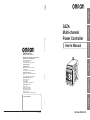
G3ZA
Multi-channel Power Controller
User’s Manual
Produced April 2004
iv
Preface
OMRON products are manufactured for use according to proper procedures by a qualified operator
and only for the purposes described in this manual.
This manual describes the functions, performance, and application methods needed for optimum use
of the G3ZA.
Please observe the following items when using the G3ZA.
• This product is designed for use by qualified personnel with a knowledge of electrical systems.
• Read this manual carefully and make sure you understand it well to ensure that you are using the
G3ZA correctly.
• Keep this manual in a safe location so that it is available for reference when required.
OMRON, 2004
All rights reserved. No part of this publication may be reproduced, stored in a retrieval system, or transmitted, in any form, or
by any means, mechanical, electronic, photocopying, recording, or otherwise, without the prior written permission of
OMRON.
No patent liability is assumed with respect to the use of the information contained herein. Moreover, because OMRON is constantly striving to improve its high-quality products, the information contained in this manual is subject to change without
notice. Every precaution has been taken in the preparation of this manual. Nevertheless, OMRON assumes no responsibility
for errors or omissions. Neither is any liability assumed for damages resulting from the use of the information contained in
this publication.
v
Read and Understand this Manual
Please read and understand this manual before using the product. Please consult your OMRON
representative if you have any questions or comments.
Warranty and Limitations of Liability
WARRANTY
OMRON's exclusive warranty is that the products are free from defects in materials and workmanship for a
period of one year (or other period if specified) from date of sale by OMRON.
OMRON MAKES NO WARRANTY OR REPRESENTATION, EXPRESS OR IMPLIED, REGARDING NONINFRINGEMENT, MERCHANTABILITY, OR FITNESS FOR PARTICULAR PURPOSE OF THE PRODUCTS.
ANY BUYER OR USER ACKNOWLEDGES THAT THE BUYER OR USER ALONE HAS DETERMINED
THAT THE PRODUCTS WILL SUITABLY MEET THE REQUIREMENTS OF THEIR INTENDED USE.
OMRON DISCLAIMS ALL OTHER WARRANTIES, EXPRESS OR IMPLIED.
LIMITATIONS OF LIABILITY
OMRON SHALL NOT BE RESPONSIBLE FOR SPECIAL, INDIRECT, OR CONSEQUENTIAL DAMAGES,
LOSS OF PROFITS OR COMMERCIAL LOSS IN ANY WAY CONNECTED WITH THE PRODUCTS,
WHETHER SUCH CLAIM IS BASED ON CONTRACT, WARRANTY, NEGLIGENCE, OR STRICT
LIABILITY.
In no event shall the responsibility of OMRON for any act exceed the individual price of the product on which
liability is asserted.
IN NO EVENT SHALL OMRON BE RESPONSIBLE FOR WARRANTY, REPAIR, OR OTHER CLAIMS
REGARDING THE PRODUCTS UNLESS OMRON'S ANALYSIS CONFIRMS THAT THE PRODUCTS
WERE PROPERLY HANDLED, STORED, INSTALLED, AND MAINTAINED AND NOT SUBJECT TO
CONTAMINATION, ABUSE, MISUSE, OR INAPPROPRIATE MODIFICATION OR REPAIR.
Application Considerations
SUITABILITY FOR USE
OMRON shall not be responsible for conformity with any standards, codes, or regulations that apply to the
combination of products in the customer's application or use of the products.
At the customer's request, OMRON will provide applicable third party certification documents identifying
ratings and limitations of use that apply to the products. This information by itself is not sufficient for a
complete determination of the suitability of the products in combination with the end product, machine,
system, or other application or use.
The following are some examples of applications for which particular attention must be given. This is not
intended to be an exhaustive list of all possible uses of the products, nor is it intended to imply that the uses
listed may be suitable for the products.
• Outdoor use, uses involving potential chemical contamination or electrical interference, or conditions or
uses not described in this manual.
• Nuclear energy control systems, combustion systems, railroad systems, aviation systems, medical
equipment, amusement machines, vehicles, safety equipment, and installations subject to separate
industry or government regulations.
• Systems, machines, and equipment that could present a risk to life or property.
Please know and observe all prohibitions of use applicable to the products.
NEVER USE THE PRODUCTS FOR AN APPLICATION INVOLVING SERIOUS RISK TO LIFE OR
PROPERTY WITHOUT ENSURING THAT THE SYSTEM AS A WHOLE HAS BEEN DESIGNED TO
ADDRESS THE RISKS, AND THAT THE OMRON PRODUCTS ARE PROPERLY RATED AND INSTALLED
FOR THE INTENDED USE WITHIN THE OVERALL EQUIPMENT OR SYSTEM.
PROGRAMMABLE PRODUCTS
OMRON shall not be responsible for the user's programming of a programmable product, or any
consequence thereof.
vi
Disclaimers
CHANGE IN SPECIFICATIONS
Product specifications and accessories may be changed at any time based on improvements and other
reasons.
It is our practice to change model numbers when published ratings or features are changed, or when
significant construction changes are made. However, some specifications of the products may be changed
without any notice. When in doubt, special model numbers may be assigned to fix or establish key
specifications for your application on your request. Please consult with your OMRON representative at any
time to confirm actual specifications of purchased products.
DIMENSIONS AND WEIGHTS
Dimensions and weights are nominal and are not to be used for manufacturing purposes, even when
tolerances are shown.
PERFORMANCE DATA
Performance data given in this manual is provided as a guide for the user in determining suitability and does
not constitute a warranty. It may represent the result of OMRON's test conditions, and the users must
correlate it to actual application requirements. Actual performance is subject to the OMRON Warranty and
Limitations of Liability.
ERRORS AND OMISSIONS
The information in this document has been carefully checked and is believed to be accurate; however, no
responsibility is assumed for clerical, typographical, or proofreading errors, or omissions.
vii
Safety Precautions
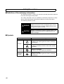
■ Definition of Precautionary Information
The following notation is used in this manual to provide precautions required
to ensure safe usage of the product.
The safety precautions that are provided are extremely important to safety.
Always read and heed the information provided in all safety precautions.
The following notation is used.
WARNING
Indicates a potentially hazardous situation which, if not
avoided, will result in minor or moderate injury, or may
result in serious injury or death. Additionally there may
be significant property damage.
CAUTION
Indicates a potentially hazardous situation which, if not
avoided, may result in minor or moderate injury or in
property damage.
■ Symbols
Symbol
Meaning
General Caution
Indicates non-specific general cautions, warnings,
and dangers.
Caution
Electrical Shock Caution
Indicates possibility of electric shock under specific
conditions.
viii
Prohibition
General Prohibition
Indicates non-specific general prohibitions.
Mandatory
Caution
General Caution
Indicates non-specific general cautions, warnings,
and dangers.
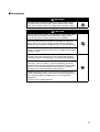
■ Precautions
WARNING
Do not touch the terminals and the wires while power is being
supplied. Doing so may possibly result in electric shock. Make
sure that the terminal cover is installed before using the product.
CAUTION
Do not allow pieces of metal, wire clippings, or fine metallic chips
or filings from installation to enter the product. Doing so may
occasionally result in electric shock, fire, or malfunction.
Do not use the product in locations of flammable or explosive
gases. Doing so may occasionally result in minor or moderate
explosion, causing minor or moderate injury, or property damage.
Do not attempt to disassemble, repair, or modify the product.
Doing so may occasionally result in minor or moderate injury due
to electric shock.
Perform correct setting of the product according to the application.
Failure to do so may occasionally cause unexpected operation,
resulting in minor or moderate injury, or damage to the equipment.
Ensure safety in the event of product failure by taking safety
measures, such as installing a separate monitoring system to
provide alarms for preventing excessive temperature rise. Product
failure may occasionally prevent control operation, resulting in
damage to the connected facilities and equipment.
Tighten the terminal screws securely using a tightening torque
within the following ranges. Loose screws may occasionally cause
fire, resulting in minor or moderate injury, or damage to the
equipment.
Terminal screws: 0.40 to 0.56 N·m
ix
Precautions for Safe Use
(1) Do not use the product in the following locations.
• Locations subject to direct radiant heat from heating equipment
• Locations where the product may come into contact with water or oil
• Locations subject to direct sunlight
• Locations where dust or corrosive gases (in particular, sulfuric or ammonia gas)
are present
• Locations subject to extreme temperature changes
• Locations where icing or condensation may occur
• Locations subject to excessive shocks or vibration
(2) Use this product within the rated load and power supply.
(3) Ensure that the rated voltage is achieved no longer than 2 s after turning the
power ON.
(4) Use/store within the rated temperature and humidity ranges. Provide forcedcooling if required.
(5) Minimum mounting distance of G3ZA is 10 mm.
When mounting the G3ZA near the SSRs, mount the G3ZA so as to not interfere
with the heat dissipation of the SSR.
(6) Use the specified size of insulated type crimp terminals (M3, width: 5.8 mm max.)
for wiring and attach insulative sleeves. To connect bare wires, use AWG22
(cross section: 0.326 mm2) to AWG14 (cross section: 2.081 mm2) to wire the
power supply terminals and AWG22 (cross section: 0.326 mm2) to AWG16 (cross
section: 1.039 mm2) for other terminals.
(7) Be sure to confirm the correct terminal and polarity when wiring the terminal
block and connectors.
(8) Do not connect any conductors to unused terminals.
(9) In order to prevent inductive noise, wire the lines connected to the product
separately from power lines carrying high voltages or currents. Do not wire in
parallel with or in the same cable as power lines. Other measures for reducing
noise include running lines along separate ducts and using shield lines.
(10) Attach a surge suppressor or noise filter to peripheral devices that generate noise
(in particular, motors, transformers, solenoids, magnetic coils or other equipment
that have an inductance component).
Do not install the product near devices generating strong high-frequency fields or
surges. When using a noise filter, check the voltage and current and install it as
close to the product as possible.
(11) For a safety disconnection of the power-line in the application the equipment shall
be provided with disconnecting devices suitable for isolation.
(e.g. circuit breakers IEC60947-2, power switches IEC60947-3, power plugs etc.)
(12) The G3ZA is for single-phase loads only. Connect only single-phase zero-cross
SSRs.
Do not connect three-phase SSRs, magnetic relays, or SSRs that do not have
zero-cross function.
x
TABLE OF CONTENTS
SECTION 1
Overview . . . . . . . . . . . . . . . . . . . . . . . . . . . . . . . . . . . . . . . . .
1-1
1
Features . . . . . . . . . . . . . . . . . . . . . . . . . . . . . . . . . . . . . . . . . . . . . . . . . . . . . . . . . . . . . . . . .
2
SECTION 2
Preparations . . . . . . . . . . . . . . . . . . . . . . . . . . . . . . . . . . . . . .
5
2-1
Installation . . . . . . . . . . . . . . . . . . . . . . . . . . . . . . . . . . . . . . . . . . . . . . . . . . . . . . . . . . . . . . .
6
2-2
How To Use the Terminals . . . . . . . . . . . . . . . . . . . . . . . . . . . . . . . . . . . . . . . . . . . . . . . . . .
9
SECTION 3
Using the G3ZA. . . . . . . . . . . . . . . . . . . . . . . . . . . . . . . . . . . .
13
3-1
Communications Settings . . . . . . . . . . . . . . . . . . . . . . . . . . . . . . . . . . . . . . . . . . . . . . . . . . .
14
3-2
CompoWay/F Frame Structure . . . . . . . . . . . . . . . . . . . . . . . . . . . . . . . . . . . . . . . . . . . . . . .
15
3-3
FINS-mini Text . . . . . . . . . . . . . . . . . . . . . . . . . . . . . . . . . . . . . . . . . . . . . . . . . . . . . . . . . . .
17
3-4
Variable Area Write . . . . . . . . . . . . . . . . . . . . . . . . . . . . . . . . . . . . . . . . . . . . . . . . . . . . . . . .
17
3-5
Variable Area Read . . . . . . . . . . . . . . . . . . . . . . . . . . . . . . . . . . . . . . . . . . . . . . . . . . . . . . . .
18
3-6
Operation Command . . . . . . . . . . . . . . . . . . . . . . . . . . . . . . . . . . . . . . . . . . . . . . . . . . . . . . .
19
3-7
Controller Attribute Read . . . . . . . . . . . . . . . . . . . . . . . . . . . . . . . . . . . . . . . . . . . . . . . . . . .
20
3-8
Controller Status Read. . . . . . . . . . . . . . . . . . . . . . . . . . . . . . . . . . . . . . . . . . . . . . . . . . . . . .
21
3-9
Echo-back Test. . . . . . . . . . . . . . . . . . . . . . . . . . . . . . . . . . . . . . . . . . . . . . . . . . . . . . . . . . . .
22
SECTION 4
Functions . . . . . . . . . . . . . . . . . . . . . . . . . . . . . . . . . . . . . . . . .
23
4-1
Changing the Manipulated Variable . . . . . . . . . . . . . . . . . . . . . . . . . . . . . . . . . . . . . . . . . . .
24
4-2
Offsetting Control Output ON Timing . . . . . . . . . . . . . . . . . . . . . . . . . . . . . . . . . . . . . . . . .
25
4-3
Turning OFF the Control Output . . . . . . . . . . . . . . . . . . . . . . . . . . . . . . . . . . . . . . . . . . . . . .
25
4-4
Detecting Heater Burnout (4-channel Models Only) . . . . . . . . . . . . . . . . . . . . . . . . . . . . . .
26
4-5
Detecting Heater Overcurrent (4-channel Models Only) . . . . . . . . . . . . . . . . . . . . . . . . . . .
28
4-6
Detecting SSR Short Circuits (4-channel Models Only). . . . . . . . . . . . . . . . . . . . . . . . . . . .
28
4-7
Setting Operation for Errors . . . . . . . . . . . . . . . . . . . . . . . . . . . . . . . . . . . . . . . . . . . . . . . . .
30
4-8
Detecting Communications Timeouts . . . . . . . . . . . . . . . . . . . . . . . . . . . . . . . . . . . . . . . . .
30
SECTION 5
Troubleshooting . . . . . . . . . . . . . . . . . . . . . . . . . . . . . . . . . . .
31
5-1
Errors . . . . . . . . . . . . . . . . . . . . . . . . . . . . . . . . . . . . . . . . . . . . . . . . . . . . . . . . . . . . . . . . . . .
32
5-2
Handling Problems . . . . . . . . . . . . . . . . . . . . . . . . . . . . . . . . . . . . . . . . . . . . . . . . . . . . . . . .
33
Appendix . . . . . . . . . . . . . . . . . . . . . . . . . . . . . . . . . . . . . . . . .
35
Index. . . . . . . . . . . . . . . . . . . . . . . . . . . . . . . . . . . . . . . . . . . . .
43
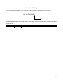
Revision History . . . . . . . . . . . . . . . . . . . . . . . . . . . . . . . . . . .
45
xi
xii
About this Manual:
This manual describes the installation and operation of the G3ZA Multi-channel Power Controller and
includes the sections described below.
Please read this manual carefully and be sure you understand the information provided before
attempting to install or operate the G3ZA. Be sure to read the precautions provided at the beginning of
this manual.
The Preface provides precautions for using the G3ZA and information on using this manual.
Section 1 introduces the G3ZA and its features.
Section 2 describes preparations for using the G3ZA, including installation and wiring.
Section 3 describes application information, including settings, communications, and controlling operation.
Section 4 describes the functions of the G3ZA so that these functions can be used effectively according to the application.
Section 5 provides information on problems that may occur during operation and corrective measures.
The Appendix provides G3ZA specifications, tables of settings, and other information.
!WARNING Failure to read and understand the information provided in this manual may result in personal injury or death, damage to the product, or product failure. Please read each section
in its entirety and be sure you understand the information provided in the section and
related sections before attempting any of the procedures or operations given.
xiii
xiv
This section introduces the G3ZA and its features.
1-1
Features . . . . . . . . . . . . . . . . . . . . . . . . . . . . . . . . . . . . . . . . . . . . . . . . . . . . . .
2
1
Overview
SECTION 1
Overview
Section 1-1
Features
Features
Overview
1-1
The G3ZA is a Multi-channel Power Controller with externally connected
SSRs. It can receive manipulated variables from a PLC or other host via RS485 communications and control heater power with high precision via the
SSRs.
Overview
Optimum Cycle Control
• Optimum cycle control is performed by driving SSRs according to load
power detection and trigger signals. (Zero-cross SSRs are used.)
• Noise is suppressed while ensure high-speed response by turning outputs ON and OFF each half cycle to achieve high-precision temperature
control.
1/5th ON (20%)
Manipulated
variable: 20%
Offset Control
• The timing of turning ON the control outputs for G3ZA channels can be
offset.
Manipulated Value
Calculations
• The manipulated variable can be calculated for one channel and the calculated value can be output for another channel.
Error Detection (4-channel
Controllers Only)
• The current flowing through the heater can be monitored to detect heater
burnouts, heater overcurrents, and SSR short circuits.
Number of Outputs
Connected
• Between one and four outputs can be connected to 4-channel Controllers
and between one and eight outputs can be connected to 8-channel Controllers.
Alarm Output
• An open-collector output terminal can be used to inform the host of errors
without using communications.
Installation
• RS-485 communications can be used to set and operate the G3ZA,
reducing the amount of wiring required between the G3ZA and host.
• Up to 31 Controllers can be connected to one communications line. With
4-channel Controllers, up to 124 channels can be controlled, and with 8channel Controllers, up to 248 channels can be controlled.
The following four models are available.
No. of channels
4 channels
Error detection
Supported
Load power supply
100 to 240 V
8 channels
Not supported
400 to 480 V
100 to 240 V
400 to 480 V
2
Section 1-1
Features
Overview
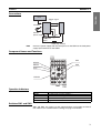
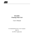
Connections
Host
Trigger signal
SSR
G3ZA
RS-485
Control
power supply
CT
Load power
supply
Load (e.g., heater)
Note
Connect a power supply with the same phase as the SSRs to the load power
supply input terminals on the G3ZA.
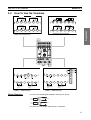
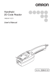
Component Names and Functions
SW1
READY
SW2
SD/RD
OCC
READY
SD/ RD
SW1
OCC
SW2
ERROR
ERROR
Operation Indicators
Operation indicator
Meaning
READY
SD/RD
Lit while power is being supplied.
Lit while communicating with the host.
OCC
ERROR
Lit while a control output is ON.
Lights or flashes when an error is detected.
Switches SW1 and SW2
SW1 and SW2 are used to set the communications unit number and baud
rate. Refer to 3-1 Communications Settings on page 14 for details.
3
Overview
Features
4
Section 1-1
SECTION 2
Preparations
2-1
Installation. . . . . . . . . . . . . . . . . . . . . . . . . . . . . . . . . . . . . . . . . . . . . . . . . . . .
6
2-2
How To Use the Terminals . . . . . . . . . . . . . . . . . . . . . . . . . . . . . . . . . . . . . . .
9
Preparations
This section describes preparations for using the G3ZA, including installation and wiring.
5
Section 2-1
Installation
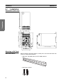
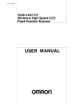
2-1
Installation
4.6 dia.
10.5
Preparations
91
Dimensions (Unit: mm)
43
SD/RD
84
READY
63
76 max. (75 typical)
9
7×5=35
SW 1
OCC
SW 2
ERROR
5
4.
9
5.6
R
111 max. (110 typical)
R
35±0.3
2.
3
45 max.
Mounting to DIN Track
DIN Track Products
When installing a DIN Track inside a control panel, secure the DIN Track with
screws in at least three locations.
• DIN Track: PFP-50N (50 cm) or PFP-100N (100 cm)
• End Plates: PFP-M
6
Section 2-1
Installation
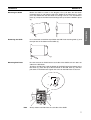
Mounting the G3ZA
Mount the G3ZA as shown in the diagram. First, pull down the DIN Track
mounting hook (1) and hook the top of the G3ZA on the DIN Track (2). Then
press the G3ZA onto the DIN Track far enough so that it can be locked in
place (3) and push the DIN Track mounting hook up to lock the G3ZA in place
(4).
(3)
(1)
Removing the G3ZA
(4)
Use a flat-blade screwdriver to pull down the DIN Track mounting hook (1) and
then pull out on the bottom of the G3ZA (2).
(2)
(1)
Mounting End Plates
Be sure to mount an End Plate on each side of the G3ZA so that it does not
slide on the DIN Track.
To mount an End Plate, hook the bottom of the End Plate on the bottom of the
DIN Track (1), place the top of the End Plate on the DIN Track (2), and then
pull down on the End Plate. Tighten the screw on the End Plate to secure it.
(2)
(1)
READY
SD/RD
SW 1
OCC
SW 2
ERROR
Note
Always mount one End Plate on each side of the G3ZA.
7
Preparations
(2)
Section 2-1
Installation
Mounting the G3ZA with Screws
Mounting Hole
Dimensions (Unit: mm)
Two, 4.2 dia. or M4 holes
Preparations
84 ±0.3
35 ±0.3
8
Section 2-2
How To Use the Terminals
How To Use the Terminals
+
19
Trigger output
12 V, 21 mA
Trigger
+
output
12 V,
21 mA
CH5
+
13
−
20
21
22
CH6
COM
CH7
Trigger output
12 V, 21 mA
+ Trigger
output
12 V,
21 mA
CH1
+
−
+
14
15
16
CH2
COM
CH3
Trigger output
12 V, 21 mA
+ Trigger
output
12 V,
21 mA
−
CT
CT
23
24
19
20
CH8
COM
CH1
CH2
Trigger output
12 V, 21 mA
+ Trigger
output
12 V,
21 mA
−
+
17
18
13
CH4
COM
CH1
CT
21
COM
Trigger output
12 V, 21 mA
Trigger
+ output
12 V,
21 mA
−
CT
22
23
24
CH3
CH4
COM
+
14
15
16
CH2
COM
CH3
Trigger output
−
12 V, 21 mA
Trigger
+ output
12 V,
21 mA
17
18
CH4
COM
Preparations
2-2
G3ZA-4H@03-FLK-UTU
G3ZA-8A@03-FLK-UTU
READY
SD/RD
SW 1
OCC
SW 2
ERROR
A
B
7
8
RS-485
+
9
7
11
8
RS-485
+
−
Alarm output
30 V, 50 mA
−
Alarm output
30 V, 50 mA
1
2
Control power supply
100 to 240 VAC
50/60 Hz
6
4
Load power supply
100 to 240 VAC
50/60 Hz
G3ZA-@@203-FLK-UTU
Wiring Diagrams
1
2
Control power supply
100 to 240 VAC
50/60 Hz
4
6
Load power supply
400 to 480 VAC
50/60 Hz
G3ZA-@@403-FLK-UTU
Use one of the following M3 solderless terminals for wiring.
5.8 mm max.
5.8 mm max.
Use wires that are rated to withstand 70 °C minimum.
9
Section 2-2
How To Use the Terminals
Controller Power Supply
Terminals
In the wiring diagrams, the area within the lines indicating terminals numbers
is inside the G3ZA and the area outside the lines are outside the G3ZA.
• Connect terminals 1 and 2 as follows:
1
2
READY
SD/ RD
SW1
OCC
SW2
ERROR
Preparations
• The input power is 100 to 240 VAC.
Load Power Supply Input
Terminals
• To detect the zero-cross point of the load supply, connect the load power
supply to terminals 4 and 6 as follows:
4
6
READY
SD/ RD
SW1
OCC
SW2
ERROR
The voltage of the load power supply that can be connected depends on
the model of the Controller.
100 to 240 VAC or 400 to 480 VAC
• The G3ZA detects the zero cross point of the load power supply.
Communications
Terminals
• To communicate with a host system, connect the communications line to
terminals 7 and 8 as follows:
7
8
B
READY
SW1
OCC
A
(+)
SD/ RD
(- )
RS-485
SW2
ERROR
• The connection type can be 1: 1 or 1: N. For 1: N connections, up to 32
Units can be connected, including the host.
• The maximum cable length is 500 m total.
Cable Diagram (Reference)
• Use shielded twisted-pair cables (AWG28 to AWG16).
AWG28
Cross-sectional area of core:
0.081 mm2 min.
• A terminator must be connected to both ends of the communications path
(including the PLC). Use a resistance of 100 to 125 Ω (1/2 W) in the terminators.
• Use an RS-232C/RS-485 converter to connect to a personal computer or
other host with an RS-232C connection.
10
Section 2-2
How To Use the Terminals
Converter: K3SC RS-232C/RS-485 Interface Converter
K32-23209
Adapter
K3SC-10
RS-232C/RS-485
Converter
RS-232C
D-sub, 9-pin
(straight)
(B)
(A)
(B)
(A)
(B)
Preparations
Terminator
100 to 125 Ω (1/2 W)
(A)
3ZA
G3ZA
(No. 0)
Terminator
100 to 125 Ω (1/2 W)
Alarm Output Terminals
for the G3ZA-@@203-FLKUTU
G3ZA
(No. 31)
G3ZA
(No. 1)
Terminator
100 to 125 Ω (1/2 W)
• Alarms are output on terminals 9 and 11.
9
11
SUB
READY
SD/ RD
SW1
OCC
SW2
ERROR
Alarm Output Terminals
for the G3ZA-@@403-FLKUTU
• The alarm output specifications are as follows:
Maximum load voltage: 30 VDC
Maximum load current: 50 mA
Maximum residual voltage: 1.5 V
Maximum leakage current: 1 mA
• Alarms are output on pins A and B of the connector.
• The alarm output specifications are as follows:
A
B
READY
SD/ RD
SW1
OCC
SUB
Maximum load voltage: 30 VDC
Maximum load current: 50 mA
Maximum residual voltage: 1.5 V
Maximum leakage current: 1 mA
SW2
ERROR
• The C-Grid SL connector for Molex Incorporated can be used for the connector.
Model number: 51030-6030
C-Grid SL Housing
Model number: 52109-0660
C-Grid SL Housing/Press-fit Type
• The G3ZA-A300C Cable from OMRON also can be used.
11
Section 2-2
How To Use the Terminals
Trigger Output Terminals
• The trigger outputs for channels 1 to 4 are output on terminals 13 to 18.
CH3
SSR
CH1
SSR
CH2
SSR
13
14
+
15
−
+
16
SD/ RD
SW1
SW2
17
+
12 VDC,
12 VDC, 21 mA
21 mA
READY
OCC
CH4
SSR
18
−
+
12 VDC,
21 mA
12 VDC,
21 mA
ERROR
Output voltage: 12 VDC ±15%
PNP
Preparations
Maximum load current: 21 mA
Short-circuit protection circuit provided.
Controllers without a Current Transformer Input Circuit (G3ZA-8A@03FLK-UTU)
• The trigger outputs for channels 5 to 8 are output on terminals 19 to 24.
CH7
SSR
CH5
SSR
CH8
SSR
CH6
SSR
19
+
20
21
−
+
22
+
24
+
12 VDC,
12 VDC, 21 mA
21 mA
Current Transformer Input
Terminals
23
12 VDC,
21 mA
12 VDC,
21 mA
−
Controllers with Built-in Current Transformer Circuits (G3ZA-4H@03FLK-UTU)
• Connect terminals 19 to 24 to the current transformers (no polarity) to
detect heater burnouts, heater overcurrents, and SSR short circuits.
CH1
CT
CH3
CT
CH2
CT
READY
SD/ RD
CH4
CT
SW1
OCC
SW2
19
20
21
22
23
24
ERROR
There are four current transformer inputs that can be used.
Use the E54-CT1 or the E54-CT3 from OMRON as the current transformer.
Wiring Example
(G3ZA-4H@03-FLKUTU)
Heater
CT
READY
SD/RD
SW1
OCC
SW2
Alarm
ERROR
Host PLC
SSR
Power Controller
power supply
12
Load power supply
(for zero cross detection)
SECTION 3
Using the G3ZA
3-1
Communications Settings . . . . . . . . . . . . . . . . . . . . . . . . . . . . . . . . . . . . . . . .
14
3-2
CompoWay/F Frame Structure . . . . . . . . . . . . . . . . . . . . . . . . . . . . . . . . . . . .
15
3-3
FINS-mini Text . . . . . . . . . . . . . . . . . . . . . . . . . . . . . . . . . . . . . . . . . . . . . . . .
17
3-4
Variable Area Write . . . . . . . . . . . . . . . . . . . . . . . . . . . . . . . . . . . . . . . . . . . .
17
3-5
Variable Area Read . . . . . . . . . . . . . . . . . . . . . . . . . . . . . . . . . . . . . . . . . . . . .
18
3-6
Operation Command . . . . . . . . . . . . . . . . . . . . . . . . . . . . . . . . . . . . . . . . . . . .
19
3-7
Controller Attribute Read . . . . . . . . . . . . . . . . . . . . . . . . . . . . . . . . . . . . . . . .
20
3-8
Controller Status Read . . . . . . . . . . . . . . . . . . . . . . . . . . . . . . . . . . . . . . . . . .
21
3-9
Echo-back Test . . . . . . . . . . . . . . . . . . . . . . . . . . . . . . . . . . . . . . . . . . . . . . . .
22
Using the G3ZA
This section describes application information, including settings, communications, and controlling operation.
13
Section 3-1
Communications Settings
3-1
Communications Settings
G3ZA settings and operation are performed using RS-485 communications.
Communications
Specifications
Transmission path connections
Multipoint
Communications method
Sync method
RS-485
Stop-start sync
Baud rate
Transmission code
9.6, 19.2, 38.4 or 57.6 kbit/s
ASCII
Data length
Stop bits
7 or 8 bits
1 or 2 bits
Error detection
Flow control
Vertical priority: None, even, or odd
None
Communications settings are made as shown in the following table.
Using the G3ZA
Setting
Setting range
Default
Setting method
Communications unit 0 to 31
number
1
SW1
Baud rate
9.6 kbit/s
SW2
Data length
9.6, 19.2, 38.4 or
57.6 kbit/s
7 or 8 bits
7 bits
Communications
Stop bits
Parity
1 or 2 bits
None, even, odd
2 bits
Even
Communications
Communications
Send standby time
0 to 99 ms
20 ms
Communications
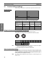
Setting the Communications Unit Number and Baud Rate
The communications unit number and baud rate are set first.
These settings are made with SW1 and SW2 on the front of the G3ZA.
SW1
SW1
Unit number
SW2
Baud rate (kbit/s)
Note
SW2
0
1
2
3
4
5
6
7
8
9
A
B
C
D
E
F
00 01 02 03 04 05 06 07 08 09 10 11 12 13 14 15
0
9.6
1
2
3
19.2 38.4 57.6
(1) Refer to Connecting More Than 16 Controllers on page 38 in the Appendix when connecting more than 16 Controllers.
(2) The default settings are shaded in the above table.
Other Communications Settings
Communications are used to set the data length, number of stop bits, parity,
and send standby time. To change the settings, use communications with the
default communications settings. Refer to 3-4 Variable Area Write on page 17
for the procedure for changing these settings.
Note
14
The settings will be enabled only when the power is turned ON again or the
G3ZA is reset.
Section 3-2
CompoWay/F Frame Structure
Send Standby Time
The send standby time is used to adjust the time required for the host to
switch from sending to receiving status. For the G3ZA, this adjusts the time
between creating a response after receiving a transmission and switching to
send status.
Host
Receive status
Send status
Send
Receive
Receive
Send
Send status
Receive status
G3ZA
Response created
Send standby time
If switching time will not cause problems, the send standby time can be shortened to reduce the communications time with the host.
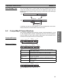
CompoWay/F Frame Structure
The propriety OMRON communications protocol called CompoWay/F is used
as the communications protocol. Commands from the host and responses
from the G3ZA are sent in data packets called frames. The structures of the
command and response frames are shown below.
Command Frames
STX Node No. Subaddress
02H
1
2
FINS-mini
command text
SID
ETX
"00"
"0"
03H
2
1
1
BCC
1
BCC calculation range
Response Frames
STX Node No. Subaddress
02H
1
End code
FINS-mini
response text
ETX
"00"
2
2
BCC
03H
2
1
1
STX
Code that indicates the beginning of the communications
frame. Always set 02H.
Node No.
This number specifies the destination. This is the same as the
communications unit number set on SW1 and SW2.
Subaddress and SID These are not used by the G3ZA. Set them to all zeros.
FINS-mini
command text
The text of the command. Refer to 3-6 Operation Command
on page 19 for details.
ETX
Code that indicates the end of the communications frame.
Always set 03H.
This stores the result of the BCC calculation from the Node
No. to EXT.
BCC
SID
STX Node No. Subaddress
FINS-mini
command text
ETX
BCC
02H 30H 30H 30H 30H 30H 30H 35H 30H 30H 03H 36H
BCC = 30H + 30H + 30H + 30H + 30H + 30H + 35H + 30H + 30H + 03H = 36H
+ indicates an exclusive OR.
15
Using the G3ZA
3-2
Section 3-2
CompoWay/F Frame Structure
End Codes (CompoWay/F Communications)
Using the G3ZA
Data Type Notation
End code
“0F”
Name
FINS command
error
Description
Could not execute the specified FINS command.
“10”
Parity error
Sum of bits that are “1” in received data does not
agree with the set communications parity value.
“11”
“12”
Framing error
Overrun error
Stop bit is “0”.
The next data was received when the received
data buffer was full.
Calculated BCC differs from received BCC.
“13”
BCC error
“14”
Format error
Characters other than “0” to “9” or “A” to “F” in
FINS-mini command text. (Refer to 3-9 Echoback Test on page 22 for echo-back tests.)
“16”
“18”
Subaddress error
Frame length error
“00”
Normal end
One or more of the subaddresses is missing.
The received frame exceeds the required number of bytes.
Command was executed normally without error.
In this manual, hexadecimal and ASCII characters are expressed as shown in
the following table.
Hexadecimal
ASCII characters
16
An H is added to the end of the hexadecimal number.
Example: 02H
ASCII characters are given in quotation marks.
Example: “00”
Section 3-3
FINS-mini Text
3-3
FINS-mini Text
The structure of FINS1 command and response text is shown below.
Command Text
SID
Node No.
Subaddress
STX
02H
"00"
MRC
SRC
2
2
FINS-mini
BCC
command text ETX
"0"
03H
Data
Response Text
STX
Node No.
End code
Subaddress
02H
"00"
ETX
FINS-mini
response text
BCC
03H
SRC
Response code
2
2
4
Data
Using the G3ZA
MRC
List of FINS-mini Service Commands
3-4
MRC
“01”
SRC
“02”
Service name
Variable Area Write
Description
Changes set values.
“01”
“30”
“01”
“05”
Variable Area Read
Operation Command
“05”
“03”
Controller Attribute Read
“06”
“01”
Controller Status Read
Reads set values.
Executes commands such as
start/stop, manipulated variable
save and software reset.
Reads the model number of the
Controller.
Reads the operating status.
“08”
“01”
Echo-back Test
Performs an echo-back test.
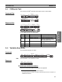
Variable Area Write
This command changes set values.
Command
Note
MRC
SRC Variable type
"01"
"02"
2
2
Write start
address
Bit position
No. of elements
Set values
"00"
4
2
2
4
No. of elements x 8 or 4
The bit position is not used. Set it to “00”.
Response
MRC
SRC
"01"
"02"
2
2
Response code
4
■ Variable Type and Write Start Address
Refer to the Parameter Tables on page 38 in the Appendix.
1.FINS: Short for Factory Interface Network Service.
The FINS protocol is used for message communications between controllers on
OMRON FA networks.
17
Section 3-5
Variable Area Read
■ Number of Elements
Specify the number of elements for which the set value is to be changed. Up
to 8 elements can be specified.
Using the G3ZA
■ Response Code
Response code
“1002”
Error name
Command length too short
Cause
The command is too short.
“1101”
Area type error
“1003”
Number of elements/Number
of data do not agree
The specified variable type
does not exist.
The specified number of elements does not agree with
the actual number of data elements.
“1100”
Parameter error
“2203”
Operation error
“0000”
Normal end
The bit position specification
is not “00”.
A set value is outside of the
setting range.
An error occurred in nonvolatile memory.
Processing was completed
normally.
Example: The following command changes the manipulated variable for
channel 1 to 50% (set value: 8 digits).
Command: [STX]010000102C10000000001000001F4[ETX][BCC]
Response: [STX]01000001020000[ETX][BCC]
Example: The following command changes the manipulated variable for
channel 1 to 50% (set value: 4 digits).
Command: [STX]01000010281000000000101F4[ETX][BCC]
Response: [STX]01000001020000[ETX][BCC]
3-5
Variable Area Read
This command reads set values.
Command
Note
MRC
SRC
"01"
"01"
2
2
Bit
Variable
type Read start address position
No. of elements
"00"
2
4
2
4
The bit position is not used. Set it to “00”.
Response
MRC
SRC
"01"
"01"
2
2
Response code
4
Set values
No. of elements x 8 or 4
■ Variable Type and Read Start Address
Refer to the Parameter Tables on page 38 in the Appendix.
■ Number of Elements
Specify the number of elements for which the set value is to be read. Up to 8
elements can be specified.
18
Section 3-6
Operation Command
■ Response Code
Response code
“1001”
Error name
Command length too long
Cause
The command is too long.
“1002”
“1101”
Command length too short
Area type error
“110B”
Response length too long
“1100”
Parameter error
“2203”
Operation error
“0000”
Normal end
The command is too short.
The specified variable type
does not exist.
The number of elements is
larger than the maximum
number allowed.
The bit position specification
is not “00”.
An error occurred in nonvolatile memory.
Processing was completed
normally.
Example: The following command reads the control variable for channel 1
(set value: 8 digits).
Command: [STX]010000101C00001000001[ETX][BCC]
Example: The following command reads the control variable for channel 1
(set value: 4 digits).
Command: [STX]010000101800001000001[ETX][BCC]
Response: [STX]010000010100000000[ETX][BCC]
3-6
Operation Command
This command is used to start and stop operation, save the manipulated variable, execute a software reset, or initialize settings.
Command
MRC
"30"
SRC
Operation Related
code information
"05"
2
2
MRC
SRC
"30"
"05"
2
2
2
2
Response
Response code
4
19
Using the G3ZA
Response: [STX]0100000101000000000000[ETX][BCC]
Section 3-7
Controller Attribute Read
1. Operation Code and Related Information
Operation
Description
code
“01”
Start/stop
Using the G3ZA
“05”
Related information
Upper digit: Channel specification Refer to 4-3 Turning OFF the Control Output
on page 25.
“0”: Channel 1
“1”: Channel 2
“2”: Channel 3
“3”: Channel 4
“4”: Channel 5
“5”: Channel 6
“6”: Channel 7
“7”: Channel 8
“F”: All channels
Lower digit: Start/stop
“0”: Start
“1”: Stop
“00”
“06”
Manipulated variable
save
Software reset
“0B”
Initialize settings
“00”
Note
Operation
Refer to 4-1 Changing the Manipulated Variable on page 24.
Performs the same processing as when the
G3ZA is turned ON.
Refer to 5-2 Handling Problems.
“00”
There is no response for a software reset. Responses are returned for all
other operation codes.
2. Response Codes
Response code
“1001”
Error name
Command length too long
The command is too long.
Cause
“1002”
“1100”
Command length too short
Parameter error
The command is too short.
The operation code or related information is not correct.
“2203”
“0000”
Operation error
Normal end
An error occurred in nonvolatile memory.
Processing was completed normally.
Example: The following command starts operation for channel 1.
Command: [STX]0100030050100[ETX][BCC]
Response: [STX]01000030050000[ETX][BCC]
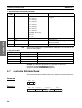
3-7
Controller Attribute Read
This command reads the model number of the Controller and the communications buffer size.
Command
MRC
SRC
"05"
"03"
2
2
MRC
SRC
"05"
"03"
2
2
Response
20
Response code
Model number
"G3ZA4
10
"
Buffer size
"00D9"
4
Section 3-8
Controller Status Read
1. Model Number
G
2. Buffer Size
3
Z
A
–
1
Code
2
3
4
Number
A
“4”
4 channels
B
“8”
“H”
8 channels
With current transformer input
C
“A”
“2”
No current transformer input
Load power supply: 100 to 240 V
DE
“4”
“03”
Load power supply: 400 to 480 V
RS-485
5
Meaning
The buffer size is 217 bytes (D9H).
Response code
“1001”
Error name
Command length too long
Cause
The command is too long.
“2203”
Operation error
An error occurred in nonvolatile memory.
“0000”
Normal end
Processing was completed
normally.
Example: The following command reads the model number and buffer size.
The response shows the Controller has four channels, supports a current
transformer, and has a load power supply of 400 to 480 V.
Command: [STX]010000503[ETX][BCC]
Response: [STX]01000005030000G3ZA-4H40300D9[ETX][BCC]
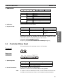
3-8
Controller Status Read
This command reads the operating status of the Controller.
Command
MRC
SRC
"06"
"01"
2
2
MRC
SRC
"06"
"01"
2
2
Response
Response code
4
Operating Related
status information
2
2
1. Operating Status
Operating status
“00”
“01”
2. Related Information
Meaning
The control output is ON for one or more channels.
The Controller is stopped or a zero cross error has
occurred during operation.
An OR of status bits 0 to 7 for all channels.
Refer to the Status in the Parameter Tables in the Appendix.
Note
To read the status of individual channels, use the Variable Area Read command for the desired channel. Refer to 3-5 Variable Area Read for details.
21
Using the G3ZA
3. Response Code
Section 3-9
Echo-back Test
3. Response Code
Response code
“1001”
Error name
Command length too long
Cause
The command is too long.
“2203”
Operation error
An error occurred in nonvolatile memory.
“0000”
Normal end
Processing was completed
normally.
Example:
Command: [STX]010000601[ETX][BCC]
Response: [STX]010000060100000100[ETX][BCC]
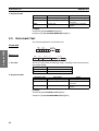
3-9
Echo-back Test
This command performs an echo-back test.
Using the G3ZA
Command
MRC
SRC
"08"
"01"
2
2
Test Data
0 to 200
Response
1. Test Data
MRC
SRC
"08"
"01"
2
2
Response code
Test Data
4
0 to 200
Set the test data within the following ranges according to the communications
data length setting.
Data length
7 bits
8 bits
Text data
ASCII 20H to 7EH
ASCII 20H to 7EH or A1H to FEH
2. Response Codes
Response code
Error name
“1001”
“2203”
Command length too long
Operation error
“0000”
Normal end
Cause
The command is too long.
An error occurred in nonvolatile memory.
Processing was completed
normally.
Example:
Command: [STX]010000801123[ETX][BCC]
Response: [STX]01000008010000123[ETX][BCC]
22
SECTION 4
Functions
This section describes the functions of the G3ZA so that these functions can be used effectively according to the
application.
Changing the Manipulated Variable . . . . . . . . . . . . . . . . . . . . . . . . . . . . . . . .
24
4-2
Offsetting Control Output ON Timing . . . . . . . . . . . . . . . . . . . . . . . . . . . . . .
25
4-3
Turning OFF the Control Output . . . . . . . . . . . . . . . . . . . . . . . . . . . . . . . . . .
25
4-4
Detecting Heater Burnout (4-channel Models Only) . . . . . . . . . . . . . . . . . . .
26
4-5
Detecting Heater Overcurrent (4-channel Models Only) . . . . . . . . . . . . . . . .
28
4-6
Detecting SSR Short Circuits (4-channel Models Only) . . . . . . . . . . . . . . . .
28
4-7
Setting Operation for Errors . . . . . . . . . . . . . . . . . . . . . . . . . . . . . . . . . . . . . .
30
4-8
Detecting Communications Timeouts. . . . . . . . . . . . . . . . . . . . . . . . . . . . . . .
30
Functions
4-1
23
Section 4-1
Changing the Manipulated Variable
4-1
Changing the Manipulated Variable
The Variable Area Write command is used to change the manipulated variable. The manipulated variable is 0.0% by default when the power supplied is
turned ON. This value can be changed to another value by using the Manipulated Variable Save operation command.
Example: The following procedure can be used to change the manipulated
variable to 20.0% whenever the power supply is turned ON.
1,2,3...
1. Execute the Variable Area Write command to set the manipulated variable
to 20.0% for all channels.
2. Execute the Manipulated Variable Save operation command.
3. The manipulated variables will be set to 20.0% the next time power is
turned ON.
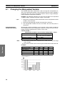
Using Manipulated
Variable Calculations
Manipulated variable calculations can be used to set the control variable for
one change based on the manipulated variable for another channel. The following calculation method and set values can be used.
Control variable =
Manipulated variable of source channel x Slope/100.0 + Offset
Note
Set value
Setting
Channels 1 to 8: Source channel
Channel 1 to 8 (Set the channel to
use as the source for calculation.)
Channels 1 to 8: Slope
Channels 1 to 8: Offset
0.0% to 400.0%
−400.0% to 400.0%
(1) The control variable will be clamped at 0% or 100% if it exceeds the range
of 0% to 100%.
(2) The control variable can be read using the Variable Area Read command.
Example:
Functions
Channel
1
2
4
Manipulated variable
Source channel
0.0
2
20.0
2
0.0
2
0.0
2
Slope
Offset
175.0
15.0
100.0
0.0
125.0
5.0
150.0
10.0
Control variable
50.0
20.0
30.0
40.0
Control variable (%)
80.0
60.0
40.0
20.0
ch1
24
3
ch2
ch3
ch4
Offsetting Control Output ON Timing
4-2
Section 4-2
Offsetting Control Output ON Timing
The ON timing of control outputs for all of the channels can be adjusted to
reduce overlapping with each other. Set the Offset Control to perform this.
(Offset Control is enabled by default.)
Disabled (No Offset)
In the following diagram, the ON timing overlaps between the channels.
ch1
ch2
ch3
ch4
Enabled (Offset)
In the following diagram, overlapping of the ON timing has been reduced.
ch1
Functions
ch2
ch3
ch4
Note
4-3
Overlapping will vary with the control variables and changes to the control
variables.
Turning OFF the Control Output
Use the start/stop operation command to turn OFF control outputs. The start/
stop command can be used for all channels or for individual channels.
Note
The start/stop status is written to nonvolatile memory. If the power is turned
OFF when a control output is stopped, it will still be stopped when power is
turned back ON. Use the Start/Stop operation command to enable operation
again.
25
Section 4-4
Detecting Heater Burnout (4-channel Models Only)
4-4
Detecting Heater Burnout (4-channel Models Only)
A heater burnout is detected by determining if the heater current is below the
heater burnout detection value when a control output is ON.
Heater Burnout
Detection Timing
Heater ON current
Hysterisis
Heater burnout detection value
ON
OFF
Status (heater burnout bit)
ERROR indicator
Alarm output
Note
Set value
Channels 1 to 4: Heater burnout detection value
Setting range
0 to 50 (See note 1.)
Default
0 (disabled)
Hysteresis (See note 2.)
1 to 10
1
(1) Heater burnouts will not be detected if the detection value is set to 0.
Detection status will be forced ON if the detection value is set to 50. Use
these to check operation during installation.
(2) Hysteresis is used to prevent chattering at the detection point. The same
hysteresis setting is used for all heater burnout detection, heater overcurrent detection, and SSR short-circuit detection functions.
Functions
Operating Conditions
• Turn ON the power supply to the heater either simultaneously with or
before the power supply to the G3ZA. False detection will occur if the
heater power supply is turned ON after the G3ZA power supply.
• The actual current flowing in the heater may not be the same as the
heater's rated current. Check the heater current under actually conditions
using the Heater ON Current parameters for channels 1 to 4.
• Keep the total normal heater current to 50 A or less. If 55 A is exceeded,
the Heater ON Current parameters for channels 1 to 4 will be 55.
• Detection will be unstable if there is only a small difference between the
normal current and burnout current. To achieve stable detection, set the
parameters so that there will be a difference of at least 2 A for heaters of
less than 10 A and a difference of 3 A or more for heaters of 10 A or more.
Heaters of less than 10 A: Normal current - burnout current ≥ 2 A
Detection will not be stable if the difference is less than 2 A.
Heaters of 10 A or more: Normal current - burnout current ≥ 3 A
Detection will not be stable if the difference is less than 3 A.
If the conditions for stable detection cannot be met, increase the number of
turns of the heater wire through the current transformer. The monitor value for
the heater ON current is proportional to the number of turns.
26
Section 4-4
Detecting Heater Burnout (4-channel Models Only)
Example:
• Heater burnout detection status can be confirmed by reading the status
for individual channels.
Calculating the Detection Current for Heater Burnout
Use the following formula to calculate the detection current.
Normal current + Burnout current
Set value =
2
When two or more heaters are connected through the current transformer, set
the detection current to detect burnouts on the heater with the smallest current. If the heater currents are all the same, set the detection current for one
wire.
Application Example
Example 1: Using one 1-kW heater (200 VAC)
SSR
Normal current =
Heater
1000
200
= 5 A (< 10 A)
1 kW
200 VAC
CT
Set value =
5+0
2
Functions
Burnout current = 0 A
= 2.5 A ≅ 2 A
(Normal current − Burnout current = 5 − 0 = 5 A (≥ 2 A))
19
21
The above calculation produces 2.5 A. The minimum setting unit is
1 A, so 2.5 is truncated and 2 A is used.
Example 2: Using three 1-kW heaters (200 VAC)
SSR
Heater
Normal current =
1000
200
Current for 1 heater =
1 kW × 3
CT
200 VAC
Set value =
1000
200
× 3 = 15 A (≥ 10 A)
× 2 = 10 A
15+10
= 12.5 A ≅ 12 A
2
(Normal current − Burnout current = 15 − 10 = 5 A ≥ 3 A)
19
21
The calculation produces 12.5 A. This is truncated to 12 A, as
explained above.
27
Section 4-5
Detecting Heater Overcurrent (4-channel Models Only)
4-5
Detecting Heater Overcurrent (4-channel Models Only)
A heater overcurrent is detected by determining if the heater current is above
the heater overcurrent detection value when a control output is ON.
Heater Overcurrent
Detection Timing
Heater overcurrent
detection value
Hysteresis
Heater ON current
ON
Status (SSR short-circuit bit)
ERROR indicator (flashing)
Alarm output
Set value
Channels 1 to 4:
Heater overcurrent
detection value
Hysteresis
(See note 2.)
Note
OFF
Setting range
0 to 50 (See note 1.)
Default
50 (disabled)
1 to 10
1
(1) Heater overcurrents will not be detected if the detection value is set to 50.
Detection status will be forced ON if the detection value is set to 0. Use
these to check operation during installation.
Functions
(2) Hysteresis is used to prevent chattering at the detection point. The same
hysteresis setting is used for all heater burnout detection, heater overcurrent detection, and SSR short-circuit detection functions.
Operating Conditions
• The actual current flowing in the heater may not be the same as the
heater's rated current. Check the heater current under actually conditions
using the Heater ON Current parameter for the relevant channel.
• Detection will be unstable if there is only a small difference between the
normal current and overcurrent current. To achieve stable detection, set
the parameters so that there will be a difference of at least 2 A for heaters
of less than 10 A and a difference of 3 A or more for heaters of 10 A or
more.
• Heater overcurrent detection status can be confirmed by reading the status for individual channels.
Calculating the Detection Current for Heater Overcurrent
Set the detection current according to the needs of the application.
4-6
Detecting SSR Short Circuits (4-channel Models Only)
An SSR short-circuit is detected by determining if the heater current is above
the SSR short-circuit detection value when a control output is OFF.
28
Section 4-6
Detecting SSR Short Circuits (4-channel Models Only)
SSR Short-circuit
Detection Timing
SSR short-circuit
detection value
Hysteresis
Heater OFF current
ON
Status (SSR short-circuit bit)
ERROR indicator
Alarm output
Set value
Note
OFF
Setting range
Default
Channels 1 to 4:
SSR short-circuit
detection value
0 to 50 (See note 1.)
50 (disabled)
Hysteresis
(See note 2.)
1 to 10
1
(1) SSR short-circuits will not be detected if the detection value is set to 50.
Detection status will be forced ON if the detection value is set to 0. Use
these to check operation during installation.
(2) Hysteresis is used to prevent chattering at the detection point. The same
hysteresis setting is used for all heater burnout detection, heater overcurrent detection, and SSR short-circuit detection functions.
Operating Conditions
• The actual current flowing in the heater may not be the same as the
heater's rated current. Check the heater current under actually conditions
using the Heater OFF Current parameters for channels 1 to 4.
Calculating the Detection Current for SSR Short-circuits
Set the detection current to the value calculated with the following formula or
higher.
Set value > Normal leakage current x 2
29
Functions
• SSR short-circuit detection status can be confirmed by reading the status
for individual channels.
Section 4-7
Setting Operation for Errors
4-7
Setting Operation for Errors
The operation to be used when the following errors occur can be set.
• Zero cross error (See note 2.)
• Heater burnout detection
• Heater overcurrent detection
• SSR short-circuit detection
Operation at error
Continues.
Continue without
error clear
Continues.
Stop
Note
Operation
Continue with error
clear
Clearing the error
The error is cleared when normal status is
recovered (i.e., the status ERROR indicator and alarm output are turned OFF).
The error is not cleared even if normal status is recovered. Restore normal status
and then use an Operation Command
Start operation again.
Stops for the
The error is not cleared even if normal stachannel with an tus is recovered and operation will
error. (See note.) remained stopped. Restore normal status
and then use an Operation Command
Start operation.
(1) Operation will stop for all channels if a zero cross error occurs.
(2) Zero cross error: A zero cross error will occur when there is an error in
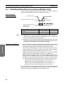
the load power supply voltage, frequency, or waveform. Refer to SECTION 5 Troubleshooting for details.
4-8
Detecting Communications Timeouts
Operation can be stopped if the time when normal communications cannot be
performed exceeds the communications timeout time.
Functions
Host
Communications
G3ZA
Operating
Stopped
Communications timeout time
Set value
Communications
timeout time
Note
Setting range
0 to 60 min
Default
0 (disabled)
(1) Communications timeouts will not be detected if the time is set to 0.
(2) The setting is not valid and communications timeout detection will not
start until the G3ZA is reset or until the power supply is cycled.
Operation will stop when a communications timeout is detected and the communications error bit in status, the ERROR indicator, and the alarm output will
turn ON. Use an Operation Command to clear the error.
30
SECTION 5
Troubleshooting
5-1
Errors. . . . . . . . . . . . . . . . . . . . . . . . . . . . . . . . . . . . . . . . . . . . . . . . . . . . . . . .
32
5-2
Handling Problems . . . . . . . . . . . . . . . . . . . . . . . . . . . . . . . . . . . . . . . . . . . . .
33
Troubleshooting
This section provides information on problems that may occur during operation and corrective measures for them.
31
Section 5-1
Errors
5-1
Errors
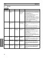
Error Table
Troubleshooting
ERROR
indicator
Status
Operation
Error
Correction
Cycle the power supply.
If operation does not recover, use the following
procedure, noting that all settings will be returned
to their default values.
• Error Response Received
Initialize the settings and perform a software
reset with an Operation Command.
• Error Response Not Received
Set the host data length, stop bits, and parity to
the default values for the G3ZA (if a Converter is
being used, set it to the same values) and then
initialize the settings and perform a software
reset with an Operation Command.
If operation still does not recover, the G3ZA
needs to be repaired.
• Check to see if the communications line is broken.
• Check to see if a communications error has
occurred.
• Check the host to see if it is functioning correctly.
• Check the information provided in 4-8 Detecting
Communications Timeouts on page 30.
Lit
No response or
an error
response
Stops
There is an
error in internal
memory or in
non-volatile
memory.
Lit
Communications error bit is
ON.
Stops
A communications timeout
has occurred.
Lit
Zero cross error According to the A zero cross
bit is ON.
operation at
error has been
error setting
detected.
Lit
Heater burnout
bit is ON.
According to the A heater burnoperation at
out has been
error setting
detected.
Lit
Heater overcurrent bit is ON.
According to the A heater overoperation at
current has
error setting
been detected.
Flashing
SSR short-circuit bit is ON.
According to the An SSR short- • The SSR has short-circuited. Replace the SSR.
operation at
circuit has been • Check the information provided in Wiring Diaerror setting
detected.
grams on page 9 and in 4-6 Detecting SSR
Short Circuits (4-channel Models Only) on
page 28.
32
• Check to see if the load power supply's voltage
and frequency are within specifications. The
specified ranges are as follows:
Controllers with 100 to 240 V Load Voltage:
75 to 264 VAC
Controllers with 400 to 480 V Load Voltage:
340 to 528 VAC
Frequency (all models) : 47 to 63 Hz
• Noise may be a factor. Check the load power
supply line for noise and check the general area
around the G3ZA for noise.
• The heater has burned out. Repair the heater or
the heater line.
• Check the information provided in 4-4 Detecting
Heater Burnout (4-channel Models Only) on
page 26.
• An overcurrent has occurred to the heater.
Return the current to the correct range.
• Check the information provided in Wiring Diagrams on page 9 and in 4-5 Detecting Heater
Overcurrent (4-channel Models Only) on
page 28.
Section 5-2
Handling Problems
Handling Problems
Handling Problems
Preliminary Checks
Check item
Items to check
Is the power supply
turned ON?
If the power supply is turned ON, the READY indicator will be
lit.
Was wiring performed correctly?
Check all of the wiring.
Were settings performed correctly?
• Check the switches to see if they are set correctly.
• Read out the settings to see if they have been set correctly.
• Read out all settings to see if any of them are incorrect.
Handling Problems
Condition
Communications
cannot be performed.
Correction
• If the SD/RD indicator does not light when communications
are attempted, there is a problem with the communications
line. Check the wiring of the communications line.
• If a communications converter is being used, check the settings of the converter to see if they are correct.
• Check the settings of SW1 and SW2 to see if they agree with
the settings of the host.
• Check the data length, number of stop bits, and parity to see
if they are the same as the host. If any of the settings are
incorrect or if any are unknown, use the following method for
communications.
1. Set SW2 to 7. (If more than 16 communications unit numbers are used, set SW2 to F.)
2. Set the baud rate, data length, number of stop bits, and parity of the host to the default values for the G3ZA.
If a converter is being used, set the converter to the same
values.
3. This should enable communications. Change all settings to
the correct values.
• Check the communications line to see if it is correct.
Outputs do not turn
ON.
• Unless the OCC indicator is lit or the control variable is set to
0.0%, then there is a problem in the wiring. Check the wiring
of the control outputs.
• If the ERROR indicator is lit or flashing, refer to the corrections given in the Error Table on page 32.
Returning settings to • Initialize the settings with an Operation Command. All of the
default values
settings can be returned to their default values. Refer to the
Parameter Tables on page 38 in the Appendix for default values.
33
Troubleshooting
5-2
Troubleshooting
Handling Problems
34
Section 5-2
Appendix
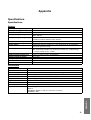
Specifications
Specifications
Ratings
Control power supply voltage
100 to 240 VAC (50/60 Hz)
Control power supply voltage range 85 to 264 VAC
Power consumption
Load power supply voltage
Load power supply voltage range
Approx. 5.9 W
100 to 240 VAC
400 to 480 VAC
Controllers for 100 to 240 VAC: 75 to 264 VAC
Controllers for 400 to 480 VAC: 340 to 528 VAC
Manipulated variable inputs
Current transformer inputs
0.0% to 100.0% (via RS-485 communications)
Single-phase AC, 0 to 50 A
Trigger outputs
One for each channel, 12 VDC ±15%, max. load current: 21 mA (with built-in
short-circuit protection circuit)
Alarm output
NPN open collector, one output
(Max. load voltage: 30 VDC, max. load current: 50 mA, max. residual voltage:
1.5 V, max. leakage current: 1.0 mA)
Indications
Ambient operating temperature
LED indicators
−10 to 55°C (with no icing or condensation)
Ambient operating humidity
Storage temperature
25% to 85%
−25 to 65°C (with no icing or condensation)
Elevation
Accessories
2,000 m max.
Instruction Sheet
Performance
Current accuracy
Insulation resistance
±3 A
100 MΩ min. (at 500 VDC) between primary and secondary
Dielectric strength
Vibration resistance
2,000 VAC, 50/60 Hz for 1 min between primary and secondary
Shock resistance
Weight of main body
300 m/s2 three times each in six directions along three axes
Approx. 200 g (including terminal cover)
Degree of protection
Memory backup
IP20
EEPROM (non-volatile memory), write life: 100,000 writes
Installation environment
Approved standards
Overvoltage category III, pollution degree 2 (according to IEC 60664-1)
UL508 (Listing), CSA22.2 No. 14
EN50178
EN61000-6-4 (EN55011: 1998, A1: 1999 Class A, Group 1)
EN61000-6-2: 2001
Appendix
Vibration frequency: 10 to 55 to 10 Hz, acceleration: 50 m/s2 in X, Y, Z directions
35
Appendix
Model Numbers
Model Numbers
G3ZA-ABCDE-F-G
Number
Code
Specifications
A
No. of control points
4
8
4 channels
8 channels
B
C
Control method
Current transformer input
None
H
Ideal cycle control
Yes
D
Load power supply voltage
A
2
None
100 to 240 VAC
E
Communications specifications
4
03
400 to 480 VAC
RS-485
F
G
Communications protocol
International standards
FLK
UTU
CompoWay/F
Approved by TÜV.
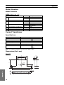
Current Transformer
Specifications
Item
Model number
Specification
E54-CT3
E54-CT1
Max. continuous heater current
Dielectric strength
50 A
1,000 VAC for 1 min
Vibration resistance
Weight
98 m/s2, 50 Hz
Approx. 11.5 g
Accessories
None
120 A (See note.)
Approx. 50 g
Connection terminals (2)
Plugs (2)
Note The maximum continuous current of the G3ZA is 50 A.
Dimensions (Unit: mm)
E54-CT1
21
15
7.5
2.8
3
10.5
25
5.8 dia.
40
Appendix
10
Two, 3.8 dia.
30
36
Appendix
E54-CT3
2.36 dia.
9
30
40
12 dia.
40
15
Two, M3 holes, depth: 4
30
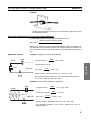
Startup Operation
It takes about 1 second for the load power supply to stabilize after the power supply to the G3ZA is turned ON.
Outputs will not turn ON during this period. A stabilization period of 1 second is also executed after clearing a
zero cross error.
Power ON
1s
Example 1 Stabilization
Normal operation
Outputs stopped
Error cleared
Example 2
Zero cross error
Normal operation
Stabilization
Outputs stopped
Error cleared
Outputs stopped
Zero cross error
Stabilization Normal operation
Outputs stopped
Appendix
Example 3 Stabilization Normal operation
37
Appendix
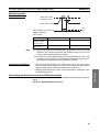
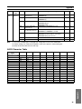
Connecting More Than 16 Controllers
If more than 16 G3ZA Controllers are connected, set SW2 to between 8 and B for the 17th Controller on. The
relationship between the settings of SW1 and SW2 is shown in the following table.
kbit/s
sw1
0
1
2
3
4
5
6
7
8
9
A
B
C
00
01
02
03
04
05
06
07
08
09
10
11
12
16
17
18
19
20
21
22
23
24
25
26
27
28
D
E
F
13
14
15
29
30
31
sw2
9.6
19.2
0
1
38.4
57.6
2
3
--9.6
4 to 7
8
19.2
38.4
9
A
57.6
---
B
C to F
Note
(1) Up to 31 Controllers can be connected.
(2) Do not set SW2 to between 4 and 7 or C and F.
(3) It's easiest to set the communications unit number first and then the baud rate.
Setting example: The following settings would be used to set a Controller to communications unit number 7
and a baud rate of 38.4 kbit/s.
SW1 = 7 and SW2 = 2
Parameter Tables
Parameter Tables
Status
Bit
31 to 13
12
11
Status
Not used.
OFF
OFF
ON
---
Start/stop
Not used.
Operating
OFF
Stopped
---
10
9
Not used.
Alarm output (applies to all channels)
OFF
OFF
--ON
8
7
Control output
Not used.
OFF
OFF
ON
---
6
5
Not used.
Communications error (applies to all channels)
OFF
No
--Yes
4
3
Zero cross error (applies to all channels)
Not used.
No
OFF
Yes
---
2
1
Heater overcurrent
SSR short circuit
No
No
Yes
Yes
0
Heater burnout
No
Yes
Example:
Appendix
Condition
Alarm output and zero cross error bit are ON.
Stopped with no errors
38
Status
H’00000210
H’00001000
Operating
Output
Error
Appendix
Operation
Variable Address
Parameter
type
C0 (See 0000
Version
note 1.) 0001
CH1 control variable
0002
CH2 control variable
Setting/monitor range
Default
Unit
---
---
---
H’00000000 to H’000003E8 (0.0 to 100.0)
H’00000000 to H’000003E8 (0.0 to 100.0)
0.0
0.0
%
%
0003
0004
CH3 control variable
CH4 control variable
H’00000000 to H’000003E8 (0.0 to 100.0)
H’00000000 to H’000003E8 (0.0 to 100.0)
0.0
0.0
%
%
0005
0006
CH5 control variable
CH6 control variable
H’00000000 to H’000003E8 (0.0 to 100.0)
H’00000000 to H’000003E8 (0.0 to 100.0)
0.0
0.0
%
%
0007
0008
CH7 control variable
CH8 control variable
H’00000000 to H’000003E8 (0.0 to 100.0)
H’00000000 to H’000003E8 (0.0 to 100.0)
0.0
0.0
%
%
0009
000A
CH1 status
CH2 status
-----
-----
000B
000C
CH3 status
CH4 status
-----
-----
000D
000E
CH5 status
CH6 status
-----
-----
000F
0010
CH7 status
CH8 status
-----
-----
0011
CH1 heater ON current
CH2 heater ON current
CH3 heater ON current
CH4 heater ON current
CH1 heater OFF current
H’00000000 to H’00000037 (0 to 55)
0
A
H’00000000 to H’00000037 (0 to 55)
0
A
H’00000000 to H’00000037 (0 to 55)
0
A
H’00000000 to H’00000037 (0 to 55)
0
A
H’00000000 to H’00000037 (0 to 55)
0
A
0016
CH2 heater OFF current
H’00000000 to H’00000037 (0 to 55)
0
A
0017
CH3 heater OFF current
H’00000000 to H’00000037 (0 to 55)
0
A
0018
CH4 heater OFF current
CH1 manipulated variable
CH2 manipulated variable
CH3 manipulated variable
H’00000000 to H’00000037 (0 to 55)
0
A
H’00000000 to H’000003E8 (0.0 to 100.0)
0.0
%
H’00000000 to H’000003E8 (0.0 to 100.0)
0.0
%
H’00000000 to H’000003E8 (0.0 to 100.0)
0.0
%
0003
CH4 manipulated vari- H’00000000 to H’000003E8 (0.0 to 100.0)
able
0.0
%
0004
CH5 manipulated vari- H’00000000 to H’000003E8 (0.0 to 100.0)
able
0.0
%
0005
H’00000000 to H’000003E8 (0.0 to 100.0)
0.0
%
H’00000000 to H’000003E8 (0.0 to 100.0)
0.0
%
H’00000000 to H’000003E8 (0.0 to 100.0)
0.0
%
0008
CH6 manipulated variable
CH7 manipulated variable
CH8 manipulated variable
CH1 slope
H’00000000 to H’00000FA0 (0.0 to 400.0)
100.0
%
0009
CH2 slope
H’00000000 to H’00000FA0 (0.0 to 400.0)
100.0
%
0012
0013
0014
0015
C1 (See 0000
note 1.)
0001
0002
0006
0007
Appendix
Level
39
Appendix
Level
Operation
Variable Address
Parameter
type
C1 (See 000A
CH3 slope
note 1.) 000B
CH4 slope
000C
CH5 slope
Unit
H’00000000 to H’00000FA0 (0.0 to 400.0)
100.0
%
H’00000000 to H’00000FA0 (0.0 to 400.0)
H’00000000 to H’00000FA0 (0.0 to 400.0)
100.0
100.0
%
%
CH6 slope
CH7 slope
H’00000000 to H’00000FA0 (0.0 to 400.0)
H’00000000 to H’00000FA0 (0.0 to 400.0)
100.0
100.0
%
%
000F
0010
CH8 slope
CH1 offset
H’00000000 to H’00000FA0 (0.0 to 400.0)
H’FFFFF060 to H’00000FA0 (−400.0 to 400.0)
100.0
0.0
%
%
0011
0012
CH2 offset
CH3 offset
H’FFFFF060 to H’00000FA0 (−400.0 to 400.0)
H’FFFFF060 to H’00000FA0 (−400.0 to 400.0)
0.0
0.0
%
%
0013
0014
CH4 offset
CH5 offset
H’FFFFF060 to H’00000FA0 (−400.0 to 400.0)
H’FFFFF060 to H’00000FA0 (−400.0 to 400.0)
0.0
0.0
%
%
0015
0016
CH6 offset
CH7 offset
H’FFFFF060 to H’00000FA0 (−400.0 to 400.0)
H’FFFFF060 to H’00000FA0 (−400.0 to 400.0)
0.0
0.0
%
%
0017
0018
CH8 offset
CH1 source channel
H’FFFFF060 to H’00000FA0 (−400.0 to 400.0)
H’00000001 to H’00000008 (1 to 8)
0.0
1
%
---
0019
001A
CH2 source channel
CH3 source channel
H’00000001 to H’00000008 (1 to 8)
H’00000001 to H’00000008 (1 to 8)
2
3
-----
001B
001C
CH4 source channel
CH5 source channel
H’00000001 to H’00000008 (1 to 8)
H’00000001 to H’00000008 (1 to 8)
4
5
-----
001D
001E
CH6 source channel
CH7 source channel
H’00000001 to H’00000008 (1 to 8)
H’00000001 to H’00000008 (1 to 8)
6
7
-----
001F
0020
CH8 source channel
CH1 heater burnout
detection value
CH2 heater burnout
detection value
CH3 heater burnout
detection value
CH4 heater burnout
detection value
H’00000001 to H’00000008 (1 to 8)
H’00000000 to H’00000032 (0 to 50)
8
0
--A
H’00000000 to H’00000032 (0 to 50)
0
A
H’00000000 to H’00000032 (0 to 50)
0
A
H’00000000 to H’00000032 (0 to 50)
0
A
0024
CH1 SSR short-circuit detection value
H’00000000 to H’00000032 (0 to 50)
50
A
0025
CH2 SSR short-circuit detection value
H’00000000 to H’00000032 (0 to 50)
50
A
0026
CH3 SSR short-circuit detection value
CH4 SSR short-circuit detection value
CH1 heater overcurrent detection value
CH2 heater overcurrent detection value
H’00000000 to H’00000032 (0 to 50)
50
A
H’00000000 to H’00000032 (0 to 50)
50
A
H’00000000 to H’00000032 (0 to 50)
50
A
H’00000000 to H’00000032 (0 to 50)
50
A
002A
CH3 heater overcurrent detection value
H’00000000 to H’00000032 (0 to 50)
50
A
002B
CH4 heater overcurrent detection value
H’00000000 to H’00000032 (0 to 50)
50
A
002C
Offset control
H'00000000 (Disabled)
H'00000001 (Enabled)
Enabled ---
0022
0023
0027
0028
0029
Appendix
Default
000D
000E
0021
40
Setting/monitor range
Appendix
Level
Operation
Variable Address
Parameter
Setting/monitor range
type
C3 (See 0000
Data length
H’00000000 (7)
note 1.)
(See note 2.)
H’00000001 (8)
0001
Stop bits (See note 2.) H’00000000 (1)
H’00000001 (2)
0002
Parity (See note 2.)
H'00000000 (None)
H'00000001 (Even)
H'00000002 (Odd)
0003
Send standby time
H’00000000 to H’00000063 (0 to 99)
(See note 2.)
0004
Communications time- H'00000000 (Disabled)
out time (See note 2.) H'00000001 to H'0000003C (1 to 60)
0005
Note
Operation at error
Default
0006
Offset value
H'00000000 (Continue with error clear)
H'00000001 (Continue with no error clear)
H'00000002 (Stop) (See note 3.)
H’00000000 to H’000003E8 (0.0 to 100.0)
0007
Hysteresis
H’00000001 to H’0000000A (1 to 10)
Unit
7
bits
2
bits
Even
---
20
ms
0
min
0
---
20.0
%
1
A
(1) If C in the variable type is changed to 8, 4-digit data can be set or monitored.
(2) These settings are valid until the G3ZA is reset or the power is turned ON again.
(3) Only the channel with the error will stop.
ASCII Character Table
0
1
2
3
4
5
6
7
0
1
NUL
SOH
DLE
DC1
SPACE
!
0
1
@
A
P
Q
a
p
q
2
3
STX
ETX
DC2
DC3
“
#
2
3
B
C
R
S
b
c
r
s
4
5
EOT
ENQ
DC4
NAK
$
%
4
5
D
E
T
U
d
e
t
u
6
7
ACK
BEL
SYN
ETB
&
’
6
7
F
G
V
W
f
g
v
w
8
9
BS
HT
CAN
EM
(
)
8
9
H
I
X
Y
h
i
x
y
A
B
LF
VT
SUB
ESC
*
+
:
;
J
K
Z
[
j
k
z
{
C
D
FF
CR
FS
GS
,
-
<
=
L
M
\
]
l
m
|
}
E
F
SO
SI
RS
US
.
/
>
?
N
O
^
_
n
o
~
DEL
Appendix
Upper byte
Lower byte
41
Appendix
Appendix
42
Index
A-B
alarm output, 2
terminals on 200-V Controllers, 11
terminals on 400-V Controllers, 11
baud rate, 14
C
communications specifications, 14
communications terminals, 10
communications timeout time, 30
communications timeouts, 30
communications unit number, 14
CompoWay/F, 15
end codes, 16
control channels
maximum number, 2
control outputs
turning OFF, 25
control power supply
terminals, 10
controller attributes
reading, 20
controller status
reading, 21
crimp terminals, 9
current transformer, 36
input terminals, 12
D
data length, 14
detecting heater burnout, 26
table, 32
F-H
FINS-mini
command and response text, 17
heater burnout, 26
calculating the detection current, 27
detection, 30
detection value, 26
heater overcurrent
calculating the detection current, 28
detection, 28, 30
detection value, 27, 28
hysteresis, 26, 28, 29
I-L
ideal cycle control, 2
initializing settings, 19
installation, 2, 6
mounting, 6
removing, 7
using screws, 8
load power supply terminals, 10
M
manipulated variable
calculations, 2
calculations using, 24
changing, 24
saving, 19
model numbers, 36
detecting heater overcurrent, 28
detecting SSR short-circuits, 28
O
OCC indicator, 3
E
E54-CT1, 36
offset control, 2, 25
offset for manipulated variable calculations, 24
echo-back test, 22
offsetting ON timing, 25
disabled, 25
enabled, 25
error detection, 2
operation command, 19
E54-CT3, 37
ERROR indicator, 3
errors
setting operation for errors, 30
43
Index
R
READY indicator, 3
resetting
software reset, 19
S
SD/RD indicator, 3
send standby time, 14, 15
set values
reading, 18
writing, 17
slope for manipulated variable calculations, 24
source channel for manipulated variable calculations, 24
specifications, 35
SSR short-circuit
calculating the detection current, 29
detection, 30
detection value, 29
SSRs, 2
starting operation, 19
startup operation, 37
stop bits, 14
stopping operation, 19
switches
SW1, 3
SW2, 3
T-Z
trigger output terminals, 12
troubleshooting, 31
handling problems, 33
wiring example, 12
zero cross errors, 30
44
Revision History
A manual revision code appears as a suffix to the catalog number on the front cover of the manual.
Cat. No. Z200-E1-01
Revision code
The following table outlines the changes made to the manual during each revision. Page numbers refer to the
previous version.
Revision code
Date
01
April 2004
Revised content
Original production
45
Revision History
46
Terms and Conditions of Sale
1. Offer; Acceptance. These terms and conditions (these "Terms") are deemed
part of all quotes, agreements, purchase orders, acknowledgments, price lists,
catalogs, manuals, brochures and other documents, whether electronic or in
writing, relating to the sale of products or services (collectively, the "Products")
by Omron Electronics LLC and its subsidiary companies (“Omron”). Omron
objects to any terms or conditions proposed in Buyer’s purchase order or other
documents which are inconsistent with, or in addition to, these Terms.
2. Prices; Payment Terms. All prices stated are current, subject to change without notice by Omron. Omron reserves the right to increase or decrease prices
on any unshipped portions of outstanding orders. Payments for Products are
due net 30 days unless otherwise stated in the invoice.
3. Discounts. Cash discounts, if any, will apply only on the net amount of invoices
sent to Buyer after deducting transportation charges, taxes and duties, and will
be allowed only if (i) the invoice is paid according to Omron’s payment terms
and (ii) Buyer has no past due amounts.
4. Interest. Omron, at its option, may charge Buyer 1-1/2% interest per month or
the maximum legal rate, whichever is less, on any balance not paid within the
stated terms.
5. Orders. Omron will accept no order less than $200 net billing.
6. Governmental Approvals. Buyer shall be responsible for, and shall bear all
costs involved in, obtaining any government approvals required for the importation or sale of the Products.
7. Taxes. All taxes, duties and other governmental charges (other than general
real property and income taxes), including any interest or penalties thereon,
imposed directly or indirectly on Omron or required to be collected directly or
indirectly by Omron for the manufacture, production, sale, delivery, importation, consumption or use of the Products sold hereunder (including customs
duties and sales, excise, use, turnover and license taxes) shall be charged to
and remitted by Buyer to Omron.
8. Financial. If the financial position of Buyer at any time becomes unsatisfactory
to Omron, Omron reserves the right to stop shipments or require satisfactory
security or payment in advance. If Buyer fails to make payment or otherwise
comply with these Terms or any related agreement, Omron may (without liability and in addition to other remedies) cancel any unshipped portion of Products sold hereunder and stop any Products in transit until Buyer pays all
amounts, including amounts payable hereunder, whether or not then due,
which are owing to it by Buyer. Buyer shall in any event remain liable for all
unpaid accounts.
9. Cancellation; Etc. Orders are not subject to rescheduling or cancellation
unless Buyer indemnifies Omron against all related costs or expenses.
10. Force Majeure. Omron shall not be liable for any delay or failure in delivery
resulting from causes beyond its control, including earthquakes, fires, floods,
strikes or other labor disputes, shortage of labor or materials, accidents to
machinery, acts of sabotage, riots, delay in or lack of transportation or the
requirements of any government authority.
11. Shipping; Delivery. Unless otherwise expressly agreed in writing by Omron:
a. Shipments shall be by a carrier selected by Omron; Omron will not drop ship
except in “break down” situations.
b. Such carrier shall act as the agent of Buyer and delivery to such carrier shall
constitute delivery to Buyer;
c. All sales and shipments of Products shall be FOB shipping point (unless otherwise stated in writing by Omron), at which point title and risk of loss shall
pass from Omron to Buyer; provided that Omron shall retain a security interest in the Products until the full purchase price is paid;
d. Delivery and shipping dates are estimates only; and
e. Omron will package Products as it deems proper for protection against normal handling and extra charges apply to special conditions.
12. Claims. Any claim by Buyer against Omron for shortage or damage to the
Products occurring before delivery to the carrier must be presented in writing
to Omron within 30 days of receipt of shipment and include the original transportation bill signed by the carrier noting that the carrier received the Products
from Omron in the condition claimed.
13. Warranties. (a) Exclusive Warranty. Omron’s exclusive warranty is that the
Products will be free from defects in materials and workmanship for a period of
twelve months from the date of sale by Omron (or such other period expressed
in writing by Omron). Omron disclaims all other warranties, express or implied.
(b) Limitations. OMRON MAKES NO WARRANTY OR REPRESENTATION,
EXPRESS OR IMPLIED, ABOUT NON-INFRINGEMENT, MERCHANTABIL-
14.
15.
16.
17.
18.
ITY OR FITNESS FOR A PARTICULAR PURPOSE OF THE PRODUCTS.
BUYER ACKNOWLEDGES THAT IT ALONE HAS DETERMINED THAT THE
PRODUCTS WILL SUITABLY MEET THE REQUIREMENTS OF THEIR
INTENDED USE. Omron further disclaims all warranties and responsibility of
any type for claims or expenses based on infringement by the Products or otherwise of any intellectual property right. (c) Buyer Remedy. Omron’s sole obligation hereunder shall be, at Omron’s election, to (i) replace (in the form
originally shipped with Buyer responsible for labor charges for removal or
replacement thereof) the non-complying Product, (ii) repair the non-complying
Product, or (iii) repay or credit Buyer an amount equal to the purchase price of
the non-complying Product; provided that in no event shall Omron be responsible for warranty, repair, indemnity or any other claims or expenses regarding
the Products unless Omron’s analysis confirms that the Products were properly handled, stored, installed and maintained and not subject to contamination, abuse, misuse or inappropriate modification. Return of any Products by
Buyer must be approved in writing by Omron before shipment. Omron Companies shall not be liable for the suitability or unsuitability or the results from the
use of Products in combination with any electrical or electronic components,
circuits, system assemblies or any other materials or substances or environments. Any advice, recommendations or information given orally or in writing,
are not to be construed as an amendment or addition to the above warranty.
See http://oeweb.omron.com or contact your Omron representative for published information.
Limitation on Liability; Etc. OMRON COMPANIES SHALL NOT BE LIABLE
FOR SPECIAL, INDIRECT, INCIDENTAL, OR CONSEQUENTIAL DAMAGES,
LOSS OF PROFITS OR PRODUCTION OR COMMERCIAL LOSS IN ANY
WAY CONNECTED WITH THE PRODUCTS, WHETHER SUCH CLAIM IS
BASED IN CONTRACT, WARRANTY, NEGLIGENCE OR STRICT LIABILITY.
Further, in no event shall liability of Omron Companies exceed the individual
price of the Product on which liability is asserted.
Indemnities. Buyer shall indemnify and hold harmless Omron Companies and
their employees from and against all liabilities, losses, claims, costs and
expenses (including attorney's fees and expenses) related to any claim, investigation, litigation or proceeding (whether or not Omron is a party) which arises
or is alleged to arise from Buyer's acts or omissions under these Terms or in
any way with respect to the Products. Without limiting the foregoing, Buyer (at
its own expense) shall indemnify and hold harmless Omron and defend or settle any action brought against such Companies to the extent based on a claim
that any Product made to Buyer specifications infringed intellectual property
rights of another party.
Property; Confidentiality. Any intellectual property in the Products is the exclusive property of Omron Companies and Buyer shall not attempt to duplicate it
in any way without the written permission of Omron. Notwithstanding any
charges to Buyer for engineering or tooling, all engineering and tooling shall
remain the exclusive property of Omron. All information and materials supplied
by Omron to Buyer relating to the Products are confidential and proprietary,
and Buyer shall limit distribution thereof to its trusted employees and strictly
prevent disclosure to any third party.
Export Controls. Buyer shall comply with all applicable laws, regulations and
licenses regarding (i) export of products or information; (iii) sale of products to
“forbidden” or other proscribed persons; and (ii) disclosure to non-citizens of
regulated technology or information.
Miscellaneous. (a) Waiver. No failure or delay by Omron in exercising any right
and no course of dealing between Buyer and Omron shall operate as a waiver
of rights by Omron. (b) Assignment. Buyer may not assign its rights hereunder
without Omron's written consent. (c) Law. These Terms are governed by the
law of the jurisdiction of the home office of the Omron company from which
Buyer is purchasing the Products (without regard to conflict of law principles). (d) Amendment. These Terms constitute the entire agreement between
Buyer and Omron relating to the Products, and no provision may be changed
or waived unless in writing signed by the parties. (e) Severability. If any provision hereof is rendered ineffective or invalid, such provision shall not invalidate
any other provision. (f) Setoff. Buyer shall have no right to set off any amounts
against the amount owing in respect of this invoice. (g) Definitions. As used
herein, “including” means “including without limitation”; and “Omron Companies” (or similar words) mean Omron Corporation and any direct or indirect
subsidiary or affiliate thereof.
Certain Precautions on Specifications and Use
1. Suitability of Use. Omron Companies shall not be responsible for conformity
with any standards, codes or regulations which apply to the combination of the
Product in the Buyer’s application or use of the Product. At Buyer’s request,
Omron will provide applicable third party certification documents identifying
ratings and limitations of use which apply to the Product. This information by
itself is not sufficient for a complete determination of the suitability of the Product in combination with the end product, machine, system, or other application
or use. Buyer shall be solely responsible for determining appropriateness of
the particular Product with respect to Buyer’s application, product or system.
Buyer shall take application responsibility in all cases but the following is a
non-exhaustive list of applications for which particular attention must be given:
(i) Outdoor use, uses involving potential chemical contamination or electrical
interference, or conditions or uses not described in this document.
(ii) Use in consumer products or any use in significant quantities.
(iii) Energy control systems, combustion systems, railroad systems, aviation
systems, medical equipment, amusement machines, vehicles, safety equipment, and installations subject to separate industry or government regulations.
(iv) Systems, machines and equipment that could present a risk to life or property. Please know and observe all prohibitions of use applicable to this Product.
NEVER USE THE PRODUCT FOR AN APPLICATION INVOLVING SERIOUS
RISK TO LIFE OR PROPERTY OR IN LARGE QUANTITIES WITHOUT
ENSURING THAT THE SYSTEM AS A WHOLE HAS BEEN DESIGNED TO
2.
3.
4.
5.
ADDRESS THE RISKS, AND THAT THE OMRON’S PRODUCT IS PROPERLY RATED AND INSTALLED FOR THE INTENDED USE WITHIN THE
OVERALL EQUIPMENT OR SYSTEM.
Programmable Products. Omron Companies shall not be responsible for the
user’s programming of a programmable Product, or any consequence thereof.
Performance Data. Data presented in Omron Company websites, catalogs
and other materials is provided as a guide for the user in determining suitability and does not constitute a warranty. It may represent the result of Omron’s
test conditions, and the user must correlate it to actual application requirements. Actual performance is subject to the Omron’s Warranty and Limitations
of Liability.
Change in Specifications. Product specifications and accessories may be
changed at any time based on improvements and other reasons. It is our practice to change part numbers when published ratings or features are changed,
or when significant construction changes are made. However, some specifications of the Product may be changed without any notice. When in doubt, special part numbers may be assigned to fix or establish key specifications for
your application. Please consult with your Omron’s representative at any time
to confirm actual specifications of purchased Product.
Errors and Omissions. Information presented by Omron Companies has been
checked and is believed to be accurate; however, no responsibility is assumed
for clerical, typographical or proofreading errors or omissions.
OMRON ELECTRONICS LLC
1 Commerce Drive
Schaumburg, IL 60173
847.843.7900
For US technical support or
other inquiries: 800.556.6766
OMRON CANADA, INC.
885 Milner Avenue
Toronto, Ontario M1B 5V8
416.286.6465
OMRON ON-LINE
Global - http://www.omron.com
USA - http://www.omron.com/oei
Canada - http://www.omron.ca
Z200-E1-01 6/06
©2006 OMRON ELECTRONICS LLC
Printed in the U.S.A.
Specifications subject to change without notice.