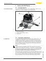
1
Operating Instructions
External display and adjustment unit
VEGADIS 82
4 … 20 mA
Document ID: 46591
Contents
Contents
1 About this document
1.1Function............................................................................................................................ 4
1.2 Target group...................................................................................................................... 4
1.3 Symbols used................................................................................................................... 4
2 For your safety
2.1 Authorised personnel........................................................................................................ 5
2.2 Appropriate use................................................................................................................. 5
2.3 Warning about incorrect use.............................................................................................. 5
2.4 General safety instructions................................................................................................ 5
2.5 CE conformity.................................................................................................................... 6
2.6 NAMUR recommendations............................................................................................... 6
2.7 Environmental instructions................................................................................................ 6
3 Product description
3.1 Configuration..................................................................................................................... 7
3.2 Principle of operation........................................................................................................ 8
3.3 Packaging, transport and storage...................................................................................... 9
3.4 Accessories and replacement parts................................................................................ 10
4Mounting
4.1 General instructions........................................................................................................ 11
4.2 Mounting instructions...................................................................................................... 11
5 Connecting to power supply
5.1 Preparing the connection................................................................................................ 14
5.2 Connection technology and steps................................................................................... 15
5.3 Wiring plan...................................................................................................................... 16
5.4 Connection signal conditioning instrument...................................................................... 16
5.5 Connection example....................................................................................................... 18
5.6 Switch-on phase............................................................................................................. 18
6 Set up with the display and adjustment module
6.1 Insert display and adjustment module............................................................................. 19
6.2 Adjustment system.......................................................................................................... 20
6.3 Measured value indication - Selection national language................................................ 20
6.4 Parameter adjustment - .................................................................................................. 21
7 Setup with PACTware
7.1 Connect the PC............................................................................................................... 26
7.2 Parameter adjustment..................................................................................................... 26
7.3 Saving the parameter adjustment data............................................................................ 27
9Dismounting
9.1 Dismounting steps.......................................................................................................... 31
2
VEGADIS 82 • 4 … 20 mA
46591-EN-140505
8 Diagnostics and service
8.1Maintenance................................................................................................................... 28
8.2 Asset Management function............................................................................................ 28
8.3 Rectify faults.................................................................................................................... 29
8.4 Exchanging the electronics module................................................................................. 30
8.5 Software update.............................................................................................................. 30
8.6 How to proceed if a repair is needed............................................................................... 30
Contents
9.2Disposal.......................................................................................................................... 31
46591-EN-140505
10Supplement
10.1 Technical data................................................................................................................. 32
10.2Dimensions..................................................................................................................... 35
Safety instructions for Ex areas
Please note the Ex-specific safety information for installation and operation in Ex areas. These safety instructions are part of the operating
instructions manual and come with the Ex-approved instruments.
Editing status: 2014-04-16
VEGADIS 82 • 4 … 20 mA
3
1 About this document
1 About this document
1.1Function
This operating instructions manual provides all the information you
need for mounting, connection and setup as well as important instructions for maintenance and fault rectification. Please read this information before putting the instrument into operation and keep this manual
accessible in the immediate vicinity of the device.
1.2 Target group
This operating instructions manual is directed to trained specialist
personnel. The contents of this manual should be made available to
these personnel and put into practice by them.
1.3 Symbols used
Information, tip, note
This symbol indicates helpful additional information.
Caution: If this warning is ignored, faults or malfunctions can result.
Warning: If this warning is ignored, injury to persons and/or serious
damage to the instrument can result.
Danger: If this warning is ignored, serious injury to persons and/or
destruction of the instrument can result.
•
→
1
Ex applications
This symbol indicates special instructions for Ex applications.
List
The dot set in front indicates a list with no implied sequence.
Action
This arrow indicates a single action.
Sequence of actions
Numbers set in front indicate successive steps in a procedure.
Battery disposal
This symbol indicates special information about the disposal of batteries and accumulators.
46591-EN-140505
4
VEGADIS 82 • 4 … 20 mA
2 For your safety
2 For your safety
2.1 Authorised personnel
All operations described in this operating instructions manual must
be carried out only by trained specialist personnel authorised by the
plant operator.
During work on and with the device the required personal protective
equipment must always be worn.
2.2 Appropriate use
The VEGADIS 82 is suitable for measured value indication in
4 … 20 mA signal current circuits.
You can find detailed information about the area of application in
chapter "Product description".
Operational reliability is ensured only if the instrument is properly
used according to the specifications in the operating instructions
manual as well as possible supplementary instructions.
For safety and warranty reasons, any invasive work on the device
beyond that described in the operating instructions manual may be
carried out only by personnel authorised by the manufacturer. Arbitrary conversions or modifications are explicitly forbidden.
2.3 Warning about incorrect use
Inappropriate or incorrect use of the instrument can give rise to
application-specific hazards, e.g. vessel overfill or damage to system
components through incorrect mounting or adjustment.
2.4 General safety instructions
This is a state-of-the-art instrument complying with all prevailing
regulations and guidelines. The instrument must only be operated in a
technically flawless and reliable condition. The operator is responsible
for the trouble-free operation of the instrument.
During the entire duration of use, the user is obliged to determine the
compliance of the necessary occupational safety measures with the
current valid rules and regulations and also take note of new regulations.
The safety instructions in this operating instructions manual, the national installation standards as well as the valid safety regulations and
accident prevention rules must be observed by the user.
46591-EN-140505
For safety and warranty reasons, any invasive work on the device
beyond that described in the operating instructions manual may be
carried out only by personnel authorised by the manufacturer. Arbitrary conversions or modifications are explicitly forbidden.
The safety approval markings and safety tips on the device must also
be observed.
VEGADIS 82 • 4 … 20 mA
5
2 For your safety
2.5 CE conformity
The device fulfills the legal requirements of the applicable EC guidelines. By affixing the CE marking, we confirm successful testing of the
product.
You can find the conformity certificate in the download section under
www.vega.com.
2.6 NAMUR recommendations
NAMUR is the automation technology user association in the process
industry in Germany. The published NAMUR recommendations are
accepted as the standard in field instrumentation.
The device fulfills the requirements of the following NAMUR recommendations:
•
NE 53 – Compatibility of field devices and display/adjustment
components
For further information see www.namur.de.
2.7 Environmental instructions
Protection of the environment is one of our most important duties.
That is why we have introduced an environment management system
with the goal of continuously improving company environmental protection. The environment management system is certified according
to DIN EN ISO 14001.
Please help us fulfill this obligation by observing the environmental
instructions in this manual:
•
•
Chapter "Packaging, transport and storage"
Chapter "Disposal"
46591-EN-140505
6
VEGADIS 82 • 4 … 20 mA
3 Product description
3 Product description
Type label
3.1 Configuration
The type label on the housing contains the most important data for
identification and use of the instrument:
1
2
3
4
5
6
7
12
11
10
9
8
Fig. 1: Layout of the type label (example)
1 Instrument type
2 Product code
3 Field for approvals
4 Electronics/Voltage supply
5 Protection rating
6 Hardware/software version
7 Order number
8 Serial number of the instrument
9 Data-Matrix-Code for Smartphone-App
10 Reminder to observe the instrument documentation
11 Device protection class
12 ID numbers, instrument documentation
Serial number - Instrument search
The type label contains the serial number of the instrument. With it
you can find the following instrument data on our homepage:
•
•
•
•
Article number (HTML)
Delivery date (HTML)
Order-specific instrument features (HTML)
Operating instructions at the time of shipment (PDF)
Go to www.vega.com, "VEGA Tools" and "Instrument search". Enter
the serial number.
As an alternative, you can access these data via your smartphone:
•
•
•
46591-EN-140505
Instrument versions
Download the smartphone app "VEGA Tools" from the "Apple App
Store" or the "Google Play Store"
Scan the Data Matrix code on the type label of the instrument or
Enter the serial number manually in the app
The VEGADIS 82 is available in different housing materials, see
chapter "Technical data".
The instrument is optionally available with or without display and
adjustment module.
Scope of this operating
instructions manual
VEGADIS 82 • 4 … 20 mA
This operating instructions manual applies to the following instrument
versions:
•
Software from 1.0.0
7
3 Product description
•
Scope of delivery
Hardware from 1.0.0
The scope of delivery encompasses:
•
•
•
Display and adjustment unit
Mounting accessories (optional)
Documentation
–– this operating instructions manual
–– Ex-specific "Safety instructions" (with Ex versions)
–– if necessary, further certificates
Information:
In this operating instructions manual, the optional instrument features
are also described. The actual range of functions is determined by the
order specification.
3.2 Principle of operation
Area of application
The VEGADIS 82 is suitable as measured value indication with
4 … 20 mA current loops. The instrument can be connected at any
point to the 4 … 20 mA signal cable. Separate, external energy is not
required.
The measured value indication is carried out in the VEGADIS 82
integrated in the display and adjustment module.
Sensors
The VEGADIS 82 is suitable for connection to any 4 … 20 mA sensors.
The instrument is particularly designed for:
•
•
VEGAPULS WL 61
VEGAWELL 52
The housing of VEGADIS 82 contains a filter element for ventilation.
Hence the insturment is also used for atmospheric pressure compensation of the submersible pressure transmitter.
The VEGADIS 82 can also be used as an external indicating device
for any four-wire sensor or a VEGAMET signal conditioning instrument with active 4 … 20 mA output.
46591-EN-140505
8
VEGADIS 82 • 4 … 20 mA
3 Product description
Connection
5
4
3
2
1
Fig. 2: Connection of VEGADIS 82 to the sensor
1 Voltage supply/Signal output sensor
2 VEGADIS 82
3 Display and adjustment module
4 4 … 20 mA signal cable
5Sensor
Packaging
3.3 Packaging, transport and storage
Your instrument was protected by packaging during transport. Its
capacity to handle normal loads during transport is assured by a test
based on ISO 4180.
The packaging of standard instruments consists of environmentfriendly, recyclable cardboard. For special versions, PE foam or PE
foil is also used. Dispose of the packaging material via specialised
recycling companies.
Transport
Transport must be carried out in due consideration of the notes on the
transport packaging. Nonobservance of these instructions can cause
damage to the device.
Transport inspection
The delivery must be checked for completeness and possible transit
damage immediately at receipt. Ascertained transit damage or concealed defects must be appropriately dealt with.
Storage
Up to the time of installation, the packages must be left closed and
stored according to the orientation and storage markings on the
outside.
46591-EN-140505
Unless otherwise indicated, the packages must be stored only under
the following conditions:
Storage and transport
temperature
VEGADIS 82 • 4 … 20 mA
•
•
•
•
•
•
•
Not in the open
Dry and dust free
Not exposed to corrosive media
Protected against solar radiation
Avoiding mechanical shock and vibration
Storage and transport temperature see chapter "Supplement Technical data - Ambient conditions"
Relative humidity 20 … 85 %
9
3 Product description
PLICSCOM
3.4 Accessories and replacement parts
The display and adjustment module PLICSCOM is used for measured
value indication, adjustment and diagnosis. It can be inserted into the
sensor or the external display and adjustment unit and removed at
any time.
You can find further information in the operating instructions "Display
and adjustment module PLICSCOM" (Document-ID 27835).
VEGACONNECT
The interface adapter VEGACONNECT enables the connection of
communication-capable instruments to the USB interface of a PC. For
parameter adjustment of these instruments, the adjustment software
PACTware with VEGA-DTM is required.
You can find further information in the operating instructions "Interface
adapter VEGACONNECT" (Document-ID 32628).
Electronics module
The electronics module is a replacement part for the display and
adjustment instrument VEGADIS 82. A separate version is available
for each type of signal output.
You can find further information in the operating instructions "Electronics module VEGADIS 82" (Document-ID 46804).
46591-EN-140505
10
VEGADIS 82 • 4 … 20 mA
4 Mounting
4Mounting
4.1 General instructions
Installation position
VEGADIS 82 functions in any installation position.
Protection against moisture
Protect your instrument against moisture penetration through the following measures:
•
•
•
•
Use the recommended cable (see chapter "Connecting to power
supply")
Tighten the cable gland
Turn the housing in such a way that the cable gland points downward
Loop the connection cable downward in front of the cable gland
This applies particularly to:
•
•
•
Wall mounting
Outdoor mounting
Installations in areas where high humidity is expected (e.g. through
cleaning processes)
Installations on cooled or heated vessels
4.2 Mounting instructions
The VEGADIS 82 is suitable for wall mounting in all available housing
materials.
7 mm
(0.28")
10 mm
(0.39")
82 mm
(3.23")
Fig. 3: Drilling dimensions for VEGADIS 82 for wall mounting
The VEGADIS 82 with plastic housing is suitable for direct carrier rail
mounting according to EN 50022.
46591-EN-140505
Carrier rail mounting
VEGADIS 82 • 4 … 20 mA
11
4 Mounting
1
2
Fig. 4: VEGADIS 82 with plastic housing for carrier rail mounting
1Base
2 Carrier rail
The versions with aluminium or stainless steel housing for carrier rail
mounting according to EN 50022 are supplied with unassembled
mounting accessories. The kit consists of an adapter plate and four
mounting screws M5 x 12.
The adapter plate is screwed to the base of VEGADIS 82 by the user.
1
2
3
Fig. 5: VEGADIS 82 with aluminium and stainless steel housing for carrier rail
mounting
1Base
2 Adapter plate with screws M5 x 12
3 Carrier rail
Tube mounting
The VEGADIS 82 for tube mounting is supplied with unassembled
mounting accessories. The kit consists of two pairs of mounting
brackets and four mounting screws M5 x 12.
The mounting brackets are screwed to the socket of VEGADIS 82 by
the user.
46591-EN-140505
12
VEGADIS 82 • 4 … 20 mA
4 Mounting
1
2
3
Fig. 6: VEGADIS 82 for tube mounting
1 4 screws M5 x 100
2 Mounting brackets
3 Tube (diameter 1" to 2")
Front panel mounting
The VEGADIS 82 is also available with a plastic housing for panel
mounting. The housing is fastened by means of the supplied screw
clamps on the rear of the panel.
1
2
3
4
5
Fig. 7: VEGADIS 82 for panel mounting
46591-EN-140505
1 Inspection window
2 Front panel
3 Screw clamp
4Housing
5 Plug connector
VEGADIS 82 • 4 … 20 mA
13
5 Connecting to power supply
5 Connecting to power supply
Safety instructions
Voltage supply
5.1 Preparing the connection
Always keep in mind the following safety instructions:
•
•
Connect only in the complete absence of line voltage
If overvoltage surges are expected, overvoltage arresters should
be installed
Power supply and current signal are carried on the same two-wire
cable. The voltage supply range can differ depending on the sensor.
The data for power supply are specified in chapter "Technical data".
Provide a reliable separation between the supply circuit and the
mains circuits according to DIN EN 61140 VDE 0140-1.
Keep in mind the following additional factors that influence the operating voltage:
•
•
Output voltage of the power supply unit can be lower under nominal load (with a sensor current of 20.5 mA resp. 22 mA in case of
fault message)
Voltage loss on the VEGADIS 82 (see supply circuit in chapter
"Technical data")
You can find information on the load resistance in chapter "Technical
data", (voltage supply of the respective sensor)
Connection cable
The instrument is connected with standard two-wire cable without
screen. If electromagnetic interference is expected which is above the
test values of EN 61326-1 for industrial areas, screened cable should
be used.
Use cable with round cross-section. To ensure the seal effect of the
cable gland (IP protection rating), find out which cable outer diameter
the cable gland is suitable for. Use a cable gland fitting the cable
diameter.
You can find an overview of the cable glands in chapter "Technical
data".
Cable gland ½ NPT
With plastic housing, the NPT cable gland or the Conduit steel tube
must be screwed without grease into the threaded insert.
Max. torque for all housings see chapter "Technical data".
Cable screening and
grounding
If screened cable is necessary, we recommend connecting the cable
screen on both ends to ground potential. In the VEGADIS 82, the
screen should be connected directly to the internal ground terminal.
In electroplating and CCP systems (cathodic corrosion protection) it
must be taken into account that significant potential differences exist.
This can lead to unacceptably high currents in the cable screen if it is
grounded at both ends.
14
VEGADIS 82 • 4 … 20 mA
46591-EN-140505
In Ex systems it must be ensured that the grounding complies with the
installation regulations.
5 Connecting to power supply
Connection technology
5.2 Connection technology and steps
The voltage supply and signal output are connected via the springloaded terminals in the housing.
Connection to the display and adjustment module or to the interface
adapter is carried out via contact pins in the housing.
Information:
The terminal block is pluggable and can be removed from the
electronics. To do this, lift the terminal block with a small screwdriver
and pull it out. When reinserting the terminal block, you should hear it
snap in.
Connection procedure
Proceed as follows:
1. Unscrew the housing cover
2. If a display and adjustment module is installed, remove it by turning it slightly to the left.
3. Loosen compression nut of the cable entry gland
4. Remove approx. 10 cm (4 in) of the cable mantle, strip approx.
1 cm (0.4 in) of insulation from the ends of the individual wires
5. Insert the cable into the sensor through the cable entry
Fig. 8: Connection steps 5 and 6
6. Insert the wire ends into the terminals according to the wiring plan
Information:
Solid cores as well as flexible cores with wire end sleeves are inserted directly into the terminal openings. In case of flexible cores without
end sleeves, press the terminal from above with a small screwdriver,
the terminal opening is then free. When the screwdriver is released,
the terminal closes again.
46591-EN-140505
You can find further information on the max. wire cross-section under
"Technical data/Electromechanical data"
7. Check the hold of the wires in the terminals by lightly pulling on
them
VEGADIS 82 • 4 … 20 mA
15
5 Connecting to power supply
8. Connect the screen to the internal ground terminal, connect the
outer ground terminal to potential equalisation
9. Tighten the compression nut of the cable entry gland. The seal
ring must completely encircle the cable
10. Reinsert the display and adjustment module, if one was installed
11. Screw the housing cover back on
Wiring plan 4 … 20 mA
5.3 Wiring plan
power supply
Sensor
(+)1
(+)3
2(-)
2
4(-)
3
1
Fig. 9: Wiring plan VEGADIS 82 for 4 … 20 mA sensors
1 To the sensor
2 Terminal for connection of the cable screen
3 For power supply
Wiring plan 4 … 20 mA panel mounting
1
2
3
4
2
1
3
Fig. 10: Wiring plan VEGADIS 82 for 4 … 20 mA sensors - panel mounting
1 To the sensor
2 Ground terminal in the switching cabinet for connection of the cable screen
3 For power supply
5.4 Connection signal conditioning instrument
16
VEGADIS 82 • 4 … 20 mA
46591-EN-140505
The following illustrations show the simplified connection of VEGADIS
82 to a signal conditioning instrument VEGAMET or a four-wire sensor with active 4 … 20 mA output.
5 Connecting to power supply
+ -
+ -
1 2
3 4
1
2
1
2
on
%
18 17 16 15 14 13 12 11 10 9 8 7 6 5
N- L1+
1
2
3
Fig. 11: Connection of the VEGADIS 82 as external indication to signal conditioning instrument or four-wire sensor
1Sensor
2 Signal conditioning instrument
3 VEGADIS 82
For this, terminals 1 and 2 on VEGADIS 82 must be bridged.
Sensor
(+)1
2
+
-
2(-)
power supply
(+)3
4(-)
1
Fig. 12: Bridge on terminals 1 and 2 on the VEGADIS 82
46591-EN-140505
1Bridge
2 VEGADIS 82
3 Signal conditioning instrument
VEGADIS 82 • 4 … 20 mA
17
5 Connecting to power supply
5.5 Connection example
(+)1
2(-)
power supply
Sensor
4...20mA
4
5
6
7
(+)1
8
3
2(-)
2
(+)3
4(-)
1
Fig. 13: Connection example 4 … 20 mA
1 Voltage supply
2 VEGADIS 82
3 Connection cable
4Sensor
5.6 Switch-on phase
After connecting the instrument to power supply or after a voltage
recurrence, the instrument carries out a self-check for approx. 10 s:
•
•
•
Internal check of the electronics
Indication of the instrument type, hardware and software version,
measurement loop name on the display or PC
Indication of a status message on the display or PC
The duration of the warm-up phase depends on the connected sensor.
Then the actual measured value will be displayed. You can find further
information of the presentation in chapter "Measured value indication
- Start menu".
46591-EN-140505
18
VEGADIS 82 • 4 … 20 mA
6 Set up with the display and adjustment module
6 Set up with the display and adjustment
module
Mount/Dismount display
and adjustment module
6.1 Insert display and adjustment module
The display and adjustment module can be inserted into VEGADIS
82 and removed again at any time. It is not necessary to interrupt the
power supply.
Proceed as follows for mounting the display and adjustment module:
1. Unscrew the housing cover
2. Place the display and adjustment module in the desired position
on the electronics (you can choose any one of four different positions - each displaced by 90°)
3. Press the display and adjustment module onto the electronics
and turn it to the right until it snaps in.
4. Screw housing cover with inspection window tightly back on
Disassembly is carried out in reverse order.
46591-EN-140505
Fig. 14: Installation of the display and adjustment module
VEGADIS 82 • 4 … 20 mA
19
6 Set up with the display and adjustment module
6.2 Adjustment system
1
2
Fig. 15: Display and adjustment elements
1 LC display
2 Adjustment keys
Key functions
•
•
•
•
Adjustment system
20
[-] key:
–– Presentation, change measured value
–– Select list entry
–– Select editing position
[+] key:
–– Change value of the parameter
[ESC] key:
–– Interrupt input
–– Jump to next higher menu
The instrument is adjusted via the four keys of the display and adjustment module. The LC display indicates the individual menu items. The
functions of the individual keys are shown in the above illustration.
Approx. 60 minutes after the last pressing of a key, an automatic reset
to measured value indication is triggered. Any values not confirmed
with [OK] will not be saved.
6.3 Measured value indication - Selection
national language
With the [->] key you can move between two different views:
First view: Display value 1 in big lettering, TAG number
VEGADIS 82 • 4 … 20 mA
46591-EN-140505
Measured value indication
[OK] key:
–– Move to the menu overview
–– Confirm selected menu
–– Edit parameter
–– Save value
6 Set up with the display and adjustment module
Second view: Display value 1, a bargraph corresponding to the
4 … 20 mA value, TAG number
During the initial setup of an instrument shipped Ex works,use the
"OK" key to get to the menu "National language".
Selection of national
language
This menu item is used to select the national language for further parameter adjustment. You can change the selection via the menu item
"Setup - Display, Menu language".
With the "OK" key you move to the main menu.
6.4 Parameter adjustment - VEGADIS 82
Main menu
The main menu is divided into four areas with the following functions:
Setup: Settings, e.g. to measurement loop name, damping, scaling
Diagnosis: Information on the device status
Additional adjustments: Reset, copy display settings
Info: Instrument name, instrument version, date of manufacture,
instrument features
For optimum adjustment of the instrument, the individual submenu
items should be selected one after the other in the main menu item
"Setup" and provided with the correct parameter values.
Setup - Measurement
loop name
In the menu item "Measurement loop name" you edit a twelve digit
measurement loop designation label.
You can enter an unambiguous designation for the measured value,
e.g. the measurement loop name or the tank or product designation.
In digital systems and in the documentation of larger plants, a singular
designation must be entered for exact identification of individual
measuring points.
46591-EN-140505
The character set comprises the following ASCII signs with extension
according to ISO 8859-1:
•
•
•
VEGADIS 82 • 4 … 20 mA
Letters from A … Z
Numbers from 0 … 9
Special characters such as +, -, /, - etc.
21
6 Set up with the display and adjustment module
Setup - Display, menu
language
This menu item allows a change of the national language.
The following languages are available:
•
•
•
•
•
•
•
•
•
•
•
Setup - Display, indication value
German
English
French
Spanish
Russian
Italian
Dutch
Portuguese
Turkish
Polish
Czech
In this menu item you can define the indication of the measured
values on the display.
The default setting for the display value is "Current".
Setup - Display, lighting
The display and adjustment module has a backlight for the display.
In this menu item you switch on the lighting. You can find the required
operating voltage in chapter "Technical data".
The lighting is switched off in delivery status.
Note:
The lighting switches off automatically when the current in the signal
circuit is lower than 4 mA.
Setup - Damping
22
To damp process-dependent measured value fluctuations, set an
integration time of 0 … 999 s in this menu item. The increment is 0.1 s.
VEGADIS 82 • 4 … 20 mA
46591-EN-140505
It switches on automatically when the current in the signal circuit is
4 mA or higher.
6 Set up with the display and adjustment module
The entered integration time influences the current value and the
display. The HART value remains unaffected.
Factory setting is 0 s.
Setup - Scaling
In the menu item "Scaling variable" you define the scaling variable
and unit of the measured value on the display, e.g. volume in l.
In addition to the offered standard units, there is the possibility, to create a user-defined unit.
Furthermore you define via the menu item "Scaling format" the position of the comma and the assignment of the measured value for 0 %
and 100 %.
Lock/unlock setup - Adjustment
In the menu item "Lock/unlock adjustment", you can protect the
instrument parameters against unauthorized modification. The PIN is
activated/deactivated permanently.
The following adjustment functions are possible without entering the
PIN:
•
•
Select menu items and show data
Read data from the sensor into the display and adjustment module.
Caution:
With active PIN, adjustment via PACTware/DTM as well as other
systems is also blocked.
46591-EN-140505
The PIN number is entered while locking.
Diagnostics - Device
status
VEGADIS 82 • 4 … 20 mA
In this menu item, the device status is displayed.
23
6 Set up with the display and adjustment module
In case of instrument failure, an error code with text message is displayed. You can find information on cause and rectification in chapter
"Diagnosis and service".
Additional adjustments
- Reset
With a reset, certain parameter adjustments carried out by the user
are reset.
The following table shows the default values of the instrument. Depending on the instrument version or application, all menu items may
not be available or some may be differently assigned:
Reset - Setup
Menu item
Parameter
Display
Measurement
loop name
Language
English
Displayed value
Signal current
Backlight
Switched off
Damping
Integration time
0 s
Scaling
Scaling size
%
Scaling format
20 mA correspond to 100.00 %
Display
Lock adjustment
Additional adjustments Copy display settings
Default value
Order-specific
4 mA correspond to 0.00 %
Released
With this function, the following display settings are copied.
The following parameters or settings are saved:
•
All parameters of the menu "Setup"
The copied data are permanently saved in the display and adjustment
module. They remain even in case of voltage loss.
Info - Instrument name
24
In this menu item, you read out the instrument name and the instrument serial number:
VEGADIS 82 • 4 … 20 mA
46591-EN-140505
Note:
Before the data are stored in the instrument, they are checked to
make sure they match the instrument. For this purpose, the instrument
type of the source data as well as the target instrument are displayed.
Storage takes place only after approval.
6 Set up with the display and adjustment module
In this menu item, the hardware and software version of the sensor is
displayed.
Info - Factory calibration
date
In this menu item, the date of the factory calibration of the instrument as well as the date of the last change of sensor parameters is
displayed via the PC.
Info - Instrument features
In this menu item, instrument features such as approvals, electronics,
housing as well as others are displayed.
46591-EN-140505
Info - Instrument version
VEGADIS 82 • 4 … 20 mA
25
7 Setup with PACTware
7 Setup with PACTware
Via interface adapter
7.1 Connect the PC
To set up the VEGADIS 82 with a PC and PACTware, the PC is connected via the interface adapter to the VEGADIS 82.
2
3
1
Fig. 16: Connection of the PC via interface adapter
1 USB cable to the PC
2 Interface adapter VEGACONNECT
3 VEGADIS 82
Prerequisites
7.2 Parameter adjustment
For parameter adjustment of the instrument via a Windows PC, the
configuration software PACTware and a suitable instrument driver
(DTM) according to FDT standard are required. The latest PACTware
version as well as all available DTMs are compiled in a DTM Collection. The DTMs can also be integrated into other frame applications
according to FDT standard.
Note:
To ensure that all instrument functions are supported, you should
always use the latest DTM Collection. Furthermore, not all described
functions are included in older firmware versions. You can download
the latest instrument software from our homepage. A description of
the update procedure is also available in the Internet.
26
VEGADIS 82 • 4 … 20 mA
46591-EN-140505
Further setup steps are described in the operating instructions manual "DTM Collection/PACTware" attached to each DTM Collection and
which can also be downloaded from the Internet. Detailed descriptions are available in the online help of PACTware and the DTMs.
7 Setup with PACTware
Fig. 17: Example of a DTM view
Standard/Full version
All device DTMs are available as a free-of-charge standard version
and as a full version that must be purchased. In the standard version,
all functions for complete setup are already included. An assistant for
simple project configuration simplifies the adjustment considerably.
Saving/printing the project as well as import/export functions are also
part of the standard version.
In the full version there is also an extended print function for complete
project documentation as well as a save function for measured value
and echo curves. In addition, there is a tank calculation program as
well as a multiviewer for display and analysis of the saved measured
value and echo curves.
The standard version is available as a download under
www.vega.com/downloads and "Software". The full version is available on CD from the agency serving you.
7.3 Saving the parameter adjustment data
46591-EN-140505
We recommend documenting or saving the parameter adjustment
data via PACTware. That way the data are available for multiple use or
service purposes.
VEGADIS 82 • 4 … 20 mA
27
8 Diagnostics and service
8 Diagnostics and service
8.1Maintenance
If the device is used correctly, no maintenance is required in normal
operation.
Sensors
8.2 Asset Management function
The instrument supports the self-monitoring and diagnosis of the connected sensor. Status or failure messages are displayed according to
the sensor via display and adjustment module, PACTware/DTM and
EDD.
You can find a detailled overview of this function in the operating
instructions of the respective sensor.
VEGADIS 82
The following table shows the error codes and text messages of the
VEGADIS 82 and gives information on the cause and removal.
Code
Cause
E003
–– CRC error during self-check –– Carry out a reset
–– Send instrument for repair
E014
–– Short-circuit or sensor current > 21 mA
E015
Sensor input:
Line break
–– Line break or sensor current –– Check cable
< 3.6 mA
–– Check sensor, probably
already in the run-in period
E021
–– Scaling span too small
–– Carry out a fresh scaling,
increase the distance
between min. and max.
scaling.
E022
–– Scaling value too high
–– Check scaling values and
correct, if necessary
E034
–– EEPROM: CRC error
–– Switch the instrument off
and on
–– Carry out reset to default
setting
–– Send instrument for repair
E035
–– ROM: CRC error
–– Switch the instrument off
and on
–– Carry out reset to default
setting
–– Send instrument for repair
Text message
CRC-error
Sensor input:
Short-circuit
Scaling: Span
too small
Scaling: Value
too high
EEPROM:
CRC error
ROM: CRC
error
–– Check cable
–– Check sensor
VEGADIS 82 • 4 … 20 mA
46591-EN-140505
28
Rectification
8 Diagnostics and service
Code
Cause
Rectification
E037
–– Error of the RAM in the
internal data memory
–– Switch the instrument off
and on
–– Carry out reset to default
setting
–– Send instrument for repair
E040
–– Hardware error
–– Switch the instrument off
and on
–– Carry out reset to default
setting
–– Send instrument for repair
Text message
RAM defective
General hardware error
8.3 Rectify faults
Reaction when malfunctions occur
The operator of the system is responsible for taking suitable measures to rectify faults.
Check the 4 … 20 mA
signal
Connect a multimeter in the suitable measuring range according to
the wiring plan. The following table describes possible errors in the
current signal and helps to remove them:
Error
Rectification
–– Set damping according to the
instrument via the display and
adjustment module or PACTware/
DTM
4 … 20 mA signal –– Electrical conmissing
nection faulty
–– Check connection according to
chapter "Connection steps" and
if necessary, correct according to
chapter "Wiring plan"
–– Voltage supply
missing
–– Check cables for breaks; repair if
necessary
–– Operating voltage too low or
load resistance
too high
–– Check, adapt if necessary
–– Electronics
module in the
sensor defective
–– Exchange the instrument or send it
in for repair
Current signal greater than
22 mA or less
than 3.6 mA
46591-EN-140505
Cause
4 … 20 mA signal –– Fluctuations of
not stable
the measured
variable
Reaction after fault rectification
Depending on the reason for the fault and the measures taken, the
steps described in chapter "Setup" must be carried out again or must
be checked for plausibility and completeness.
24 hour service hotline
Should these measures not be successful, please call in urgent cases
the VEGA service hotline under the phone no. +49 1805 858550.
The hotline is also available outside normal working hours, seven
days a week around the clock.
VEGADIS 82 • 4 … 20 mA
29
8 Diagnostics and service
Since we offer this service worldwide, the support is provided in
English. The service itself is free of charge, the only costs involved are
the normal call charges.
8.4 Exchanging the electronics module
In case of a defect, the user can replace the electronics module with
another one of identical type.
In Ex applications, only instruments and electronics modules with appropriate Ex approval may be used.
If there is no electronics module available on site, one can be ordered
from the agency serving you.
8.5 Software update
The following components are required to update the instrument
software:
•
•
•
•
•
Instrument
Voltage supply
Interface adapter VEGACONNECT
PC with PACTware
Current instrument software as file
You can find the current instrument software as well as detailed
information on the procedure under "www.vega.com/downloads" and
"Software".
Caution:
Instruments with approvals can be bound to certain software versions.
Therefore make sure that the approval is still effective after a software
update is carried out.
You can find detailed information at www.vega.com/downloads and
"Approvals".
8.6 How to proceed if a repair is needed
You can find a repair form as well as detailed information on how to
proceed at www.vega.com/downloads and "Forms and certificates".
By doing this you help us carry out the repair quickly and without having to call back for needed information.
If a repair is necessary, please proceed as follows:
•
•
•
•
VEGADIS 82 • 4 … 20 mA
46591-EN-140505
30
Print and fill out one form per instrument
Clean the instrument and pack it damage-proof
Attach the completed form and, if need be, also a safety data
sheet outside on the packaging
Please contact the agency serving you to get the address for
the return shipment. You can find the agency on our home page
www.vega.com.
9 Dismounting
9Dismounting
9.1 Dismounting steps
Warning:
Before dismounting, be aware of dangerous process conditions such
as e.g. pressure in the vessel or pipeline, high temperatures, corrosive or toxic products etc.
Take note of chapters "Mounting" and "Connecting to power supply"
and carry out the listed steps in reverse order.
9.2Disposal
The instrument consists of materials which can be recycled by specialised recycling companies. We use recyclable materials and have
designed the parts to be easily separable.
WEEE directive 2002/96/EG
This instrument is not subject to the WEEE directive 2002/96/EG and
the respective national laws. Pass the instrument directly on to a specialised recycling company and do not use the municipal collecting
points. These may be used only for privately used products according
to the WEEE directive.
Correct disposal avoids negative effects on humans and the environment and ensures recycling of useful raw materials.
Materials: see chapter "Technical data"
46591-EN-140505
If you have no way to dispose of the old instrument properly, please
contact us concerning return and disposal.
VEGADIS 82 • 4 … 20 mA
31
10 Supplement
10Supplement
10.1 Technical data
Materials and weights
Materials
ƲƲ Plastic housing
plastic PBT (Polyester)
ƲƲ Stainless steel housing
316L precision casting, blasted
ƲƲ Aluminium housing
ƲƲ Seal between housing and housing
cover
ƲƲ Inspection window in housing cover
(in version with display and adjustment module)
ƲƲ Cable gland/Seal insert
ƲƲ Ground terminal
Deviating materials - Ex-d version
ƲƲ Inspection window in housing cover
(in version with display and adjustment module)
Aluminium die-casting AlSi10Mg, powder-coated - basis:
Polyester
NBR (stainless steel housing), silicone (Alu/plastic housing)
Polycarbonate, coated
PA/NBR
316L
Single-pane safety glass (ESG)
ƲƲ Cable gland/Seal insert
Brass, nickel-plated/NBR
ƲƲ Adapter plate, housing side
316
ƲƲ Mounting screws
316
Material with carrier rail mounting
ƲƲ Adapter plate, carrier rail side
Materials with tube mounting
ƲƲ Brackets
ƲƲ Mounting screws
Material with panel mounting
Zinc die casting
StSt
StSt
ƲƲ Housing
PPE
ƲƲ Screw clamps
St, nickle plate
ƲƲ Transparent cover
PS
Weights without mounting elements approx.
ƲƲ Plastic housing
0.35 kg (0.772 lbs)
ƲƲ Stainless steel housing
2.0 kg (4.409 lbs)
ƲƲ Aluminium housing
0.7 kg (1.543 lbs)
ƲƲ Plastic housing
ƲƲ Aluminium/Stainless steel housing
32
46591-EN-140505
Torques
Max. torque for NPT cable glands and Conduit tubes
10 Nm (7.376 lbf ft)
50 Nm (36.88 lbf ft)
VEGADIS 82 • 4 … 20 mA
10 Supplement
Signal and supply circuit
Voltage drop with current value 4 … 20 mA
ƲƲ Without lighting max.
ƲƲ With lighting max.
Current range
Overcurrent resistance
Fuse
Interpolation protection
1.7 V
3.2 V
3.5 … 22.5 mA1)
100 mA
Power supply side
Available
Current measurement (reference temperature 20 °C)
Measuring range loop current
3.5 … 22.5 mA
Deviation
±0.1 % of 20 mA
Interval
250 ms
Temperature coefficient
Display and adjustment module
Display element
Measured value indication
ƲƲ Number of digits
ƲƲ Size of digits
Adjustment elements
Protection rating
ƲƲ unassembled
ƲƲ mounted into the housing without
cover
Materials
ƲƲ Housing
ƲƲ Inspection window
Ambient conditions
Storage and transport temperature
Ambient temperature
ƲƲ without display and adjustment
module
ƲƲ With display and adjustment module
46591-EN-140505
Process conditions
Vibration resistance
Vibration resistance with carrier rail
mounting
1)
±0.1 % of the span/10 K
Display with backlight
5
W x H = 7 x 13 mm
4 keys
IP 20
IP 40
ABS
Polyester foil
-40 … +80 °C (-40 … +176 °F)
-40 … +80 °C (-40 … +176 °F)
-15 … +70 °C (+5 … +158 °F)
4 g at 5 … 200 Hz according to EN 60068-2-6 (vibration
with resonance)
1 g at 5 … 200 Hz according to EN 60068-2-6 (vibration
with resonance)
If the loop current is not sufficient for operation, the display remains dark. When the measured values are outside the measuring range, a message is displayed instead of the measured value.
VEGADIS 82 • 4 … 20 mA
33
10 Supplement
Shock resistance
100 g, 6 ms according to EN 60068-2-27 (mechanical
shock)
Electromechanical data
Options of the cable entry
ƲƲ Cable entry
M20 x 1.5, ½ NPT
ƲƲ Blind plug
M20 x 1.5; ½ NPT
ƲƲ Cable gland
M20 x 1,5; ½ NPT (cable ø see below table)
ƲƲ Closing cap
½ NPT
Material cable
gland
Material seal
insert
Cable diameter
PA black
Neoprene (CR)
–
●
●
●
PA blue
Neoprene (CR)
–
●
–
–
Brass, nickelplated
NBR
●
–
–
–
Stainless steel
NBR
–
–
●
–
4 … 8.5 mm
Connection terminals
ƲƲ Type
ƲƲ Stripping length
5 … 9 mm
6 … 12 mm
10 … 14 mm
Spring-loaded terminal
8 mm
Wire cross-section of the connection cable (according to IEC 60228)
ƲƲ Massive wire, cord
ƲƲ Stranded wire with end sleeve
0.2 … 2.5 mm² (AWG 24 … 14)
0.2 … 1.5 mm² (AWG 24 … 16)
Electromechanical data - Panel mounting
Terminals, plug connector
ƲƲ Type
ƲƲ Stripping length
Spring-loaded terminal
8 mm
Wire cross-section of the connection cable (according to IEC 60228)
ƲƲ Massive wire, cord
ƲƲ Stranded wire with end sleeve
Electrical protective measures
Protection rating
0.2 … 1.5 mm² (AWG 24 … 16)
0.25 … 0.75 mm² (AWG 24 … 18)
ƲƲ Housing, plastic
IP 66/IP 67, NEMA 4X/6P
ƲƲ Housing Aluminium, stainless steel
IP 66/IP 68 (0.2 bar), NEMA 4X/6P
ƲƲ Housing, plastic - Panel mounting,
assembled
VEGADIS 82 • 4 … 20 mA
46591-EN-140505
34
IP 40, NEMA 2
10 Supplement
10.2Dimensions
VEGADIS 82 - Plastic housing
~ 69 mm
(2.72")
6,5 mm
(0.26")
85 mm
(3.35")
ø 79 mm
(3.11")
82 mm
(3.23")
97 mm
(3.82")
97 mm
(3.82")
Fig. 18: VEGADIS 82 with plastic housing
VEGADIS 82 - Plastic housing - Panel mounting
72,5 mm
(2.85")
67 mm
(2.64")
78,2 mm
(3.08")
72,5 mm
(2.85")
70 mm
(2.76")
77 mm
(3.03")
22,5 mm
(0.89")
56 mm
(2.20")
76 mm
(2.99")
46591-EN-140505
Fig. 19: VEGADIS 82 with plastic housing for panel mounting
VEGADIS 82 • 4 … 20 mA
35
10 Supplement
VEGADIS 82 - Aluminium housing
~ 75,2 mm
(2.95")
5 mm
(0.2")
87 mm
(3.43")
ø 86 mm
(3.39")
97 mm
(3.82")
82 mm
(3.23")
97 mm
(3.82")
Fig. 20: VEGADIS 82 with Aluminium housing
VEGADIS 82 - Stainless steel, precision cast housing
~ 75 mm
(2.95")
5 mm
(0.2")
87 mm
(3.43")
ø 86 mm
(3.39")
97 mm
(3.82")
82 mm
(3.23")
97 mm
(3.82")
Fig. 21: VEGADIS 82 with stainless steel, precision cast housing
46591-EN-140505
36
VEGADIS 82 • 4 … 20 mA
10 Supplement
Mounting elements
97 mm
(3.82")
82 mm
(3.23")
97 mm
(3.82")
11 mm
(0.43")
82 mm
(3.23")
7 mm
(0.28")
Fig. 22: Adapter plate for carrier rail mounting of VEGADIS 82
48...84 mm
(1.89"...3.31")
82 mm
(3.23")
20 mm
(0.79")
15 mm
(0.59")
2 mm
(0.08")
2 mm
(0.08")
mm
...60
ø 29
6")
"...2.3
4
.1
1
(
20 mm
(0.79")
M6
97 mm
(3.82")
20 mm
(0.79")
46591-EN-140505
Fig. 23: Brackets for tube mounting of VEGADIS 82
VEGADIS 82 • 4 … 20 mA
37
10 Supplement
10.3 Industrial property rights
VEGA product lines are global protected by industrial property rights. Further information see
www.vega.com.
Only in U.S.A.: Further information see patent label at the sensor housing.
VEGA Produktfamilien sind weltweit geschützt durch gewerbliche Schutzrechte.
Nähere Informationen unter www.vega.com.
Les lignes de produits VEGA sont globalement protégées par des droits de propriété intellectuelle. Pour plus d'informations, on pourra se référer au site www.vega.com.
VEGA lineas de productos están protegidas por los derechos en el campo de la propiedad industrial. Para mayor información revise la pagina web www.vega.com.
Линии продукции фирмы ВЕГА защищаются по всему миру правами на интеллектуальную
собственность. Дальнейшую информацию смотрите на сайте www.vega.com.
VEGA系列产品在全球享有知识产权保护。
进一步信息请参见网站<www.vega.com。
10.4Trademark
All the brands as well as trade and company names used are property of their lawful proprietor/
originator.
46591-EN-140505
38
VEGADIS 82 • 4 … 20 mA
INDEX
INDEX
A
Adjustment
––Menu 21
––System 20
Adjust the indication 22
Area of application 8
C
Change the language 22
Check output signal 29
Connection
––Cable 14
––Steps 15
––Technology 15
Copy display settings 24
T
Type label 7
V
Voltage supply 14
W
WEEE directive 31
D
Damping 22
Display lighting 22
E
Error codes 28
G
Grounding 14
I
Instrument versions 7
Interface adapter 26
L
Lock adjustment 23
M
Mounting
––Carrier rail 11
––Front panel 13
––Position 11
––Tube 12
––Wall 11
46591-EN-140505
R
Recycling 31
Repair 30
Reset 24
S
Scaling 23
Service hotline 29
VEGADIS 82 • 4 … 20 mA
39
All statements concerning scope of delivery, application, practical use and operating conditions of the sensors and processing systems correspond to the information
available at the time of printing.
Subject to change without prior notice
© VEGA Grieshaber KG, Schiltach/Germany 2014
VEGA Grieshaber KG
Am Hohenstein 113
77761 Schiltach
Germany
Phone +49 7836 50-0
Fax +49 7836 50-201
E-mail: [email protected]
www.vega.com
46591-EN-140505
Printing date: