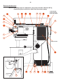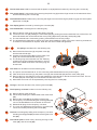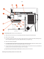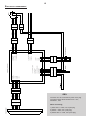
1
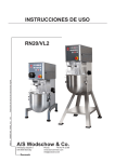
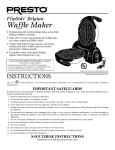
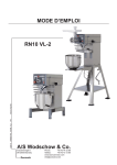
OPERATING INSTRUCTIONS
102006 ORDER NO.: 00011_VL2
GB
RN20/VL2
A/S Wodschow & Co.
Industrisvinget 6
DK-2605 Brøndby
Denmark
Phone:
+45 43 44 22 88
Telefax:
+45 43 43 12 80
www.bearvarimixer.com
[email protected]
2
CONTENTS:
GENERAL: ......................................................................................................................................................2
......................................................................................................................................................2
SAFETY:
INSTALLATION OF NEW MIXER:................................................................................................................................2
VL2 CONTROL PANEL - SURVEY OF VARIOUS OPERATING SITUATIONS: ...........................................................................3
OPERATION OF THE MIXER: ...................................................................................................................................4
THE REMIX FUNCTION: .........................................................................................................................................5
CHANGE OF FIXED SPEEDS: ..................................................................................................................................5
RESET OF TIMER: ................................................................................................................................................5
OVERLOAD: ......................................................................................................................................................5
PROCEDURE IN CASE OF OVERLOAD: ......................................................................................................................5
RECOMMENDED MAXIMUM SPEEDS: .........................................................................................................................5
CONSTRUCTION OF THE MIXER: ..............................................................................................................................6
THE MAXIMUM CAPACITY OF THE MIXER: ..................................................................................................................6
CORRECT USE OF TOOLS: .....................................................................................................................................7
CLEANING: ......................................................................................................................................................7
MAINTENANCE AND LUBRICATION: ..........................................................................................................................7
ATTACHMENT DRIVE:............................................................................................................................................7
RECOMMENDED MAX. SPEEDS FOR ATTACHMENT DRIVE: .............................................................................................7
DIMENSION SKETCHES:.........................................................................................................................................7
VL-2 CONTROL, ERROR CODES AND POSSIBLE SOLUTIONS: ........................................................................................8
TEST PROGRAMS: ...............................................................................................................................................9
SERVICE INSTRUCTIONS: .....................................................................................................................................10
CABLING DIAGRAM: ...........................................................................................................................................14
ELECTRICAL DIAGRAM:.......................................................................................................................................15
GENERAL:
In case of complaints, please contact your supplier.
We offer a guarantee period of two years from the date of invoice.
The guarantee does not cover faults resulting from faulty
operation, overloading and lacking observance of directions
of maintenance.
It should be checked that all loose parts are delivered with
the mixer such as bowl, tools and intermediate pieces.
To the attachment drive should only be connected attachments produced by A/S WODSCHOW & CO.
If the mixer is placed on a bench stand, it can be placed direct on
the floor. Foundation bolts in the floor are recommended.
Intermediate pieces can be inserted under the mixer’s feet,
if the floor is not completely even.
Connection to power:
Before the mixer is connected to power, it should be checked
that the voltage and frequency printed on the machine label
is correct in relation to the place of installation. The machine
label is placed at the top right side of the mixer.
The mixer must be connected
to earth!
SAFETY:
If not, it will cause missing function of EMC
filter as well as risk of damaging the frequency
converter.
The constant noise level of the workplace of the operator
is lower than 70 dB (A).
The mixer is designed for manufacture of products
which do not during processing cause reactions
or emit substances which may be detrimental to
the user.
Putting your fingers in the bowl while the mixer is
running may cause injuries.
INSTALLATION OF NEW MIXER:
Installation and securing:
If the mixer is placed on a table, it must always be bolted
into the table top. The bolts fixing the mixer on the pallet can be used for this, no nuts are needed as there are
threads in the bottom plate of the mixer (see page 6).
•
The mixer must only be connected to single phase power
with earth.
•
A two-pin plug with earth is to be used. Alternatively two
conductors and earth from a 3-phase power supply.
•
The mixer must be protected by a differential switch.
•
The mixer is protected by a 10A fuse. The fuse is built
into the frequency converter, which is placed in the bottom of the mixer.
3
VL2 CONTROL PANEL - SURVEY OF VARIOUS OPERATING SITUATIONS:
The following pictures show various operating situations and corresponding explanation:
1
Emergency stop is activated - there is no light in the
display. If the red diode at
is flashing, the mixer has
stopped because the safety circuit has been interrupted,
either because the bowl arms have been lowered or the
safety guard has been opened.
2
The mixer is connected to power and is ready for start
- flashing of the green diode at
will show that!
It is possible to set a start speed by pushing one of the
fixed speeds or
, before
is pushed.
When
is pushed, the mixer will start in minimum speed.
Operating time is stated by pushing
or
.
and thereafter the
A program is run by first pushing
wanted number, e.g
for program No. 1.
3
The mixer is running and a speed has been chosen four diodes on the speed indicator are alight.
The speed can be changed by pushing one of the buttons
for the four fixed speeds or
or
.
The mixer can be stopped without reset of the timer, by
pushing
or by opening the safety guard. The mixer is
restarted by pushing
.
4
has been pushed - yellow diode at
is flashing. The
mixer is started by pushing
. The timer will start again
and the speed is running up to the chosen speed. If
is
pushed, the timer is reset and the mixer will not start, but is
ready for start - green diode at
will flash (see picture 2).
4
OPERATION OF THE MIXER:
Time up
Text field (timer)
Time down
Fixed speeds
Pause
Speed indicator
REMIX-function
Speed down
Start/Stop
Emergency stop
Speed up
Is activated by pushing red
button - is deactivated by
turning red button counter
clockwise.
Before starting the mixer:
Mount the required tool in the bayonet shaft. Place the bowl
in the bowl arms and raise it to its working position by means
of the handle for bowl lift. Close the safety guard.
It is possible to change the fixed speeds - see the paragraph
„Change of fixed speeds“.
The mixer is ready for start.
Indication of operation time:
Before starting the mixer, an operation time for the mixer can
be chosen by pushing
or
. The operating time will be
shown in minutes and seconds in the timer field between
and
.
Start the mixer:
Push
to start the mixer.
Push
to increase the speed.
Push
to reduce the speed.
Or push
speeds.
,
,
or
The maximum operating time is 60 minutes.
Inspection of the ingredients during operation:
to choose one of the fixed
The speed indicator below the fields
mixing speed of the tool.
to
shows the
It is now possible to open the safety guard to check the
ingredients.
Four fixed speeds:
For quick choice of speed, use the fields
If it is wished to stop the mixer without reducing operation time
and speed, push
. The mixer will reduce speed and then
stop, the operation time will also stop.
to
.
Field
corresponds lowest speed, aprox. 98 RPM.
Field
corresponds aprox. 172 RPM.
Field
corresponds aprox. 267 RPM.
Field
corresponds maximum speed, aprox. 365 RPM.
Close the safety guard and push
, and the mixer will start
and will increase the speed to the speed chosen before pushing
. The operating time will also be continued.
If the bowl is lowered while the mixer is stopped, the operating
time is reset, and
must be pushed to restart the mixer.
5
THE REMIX FUNCTION:
RESET OF TIMER:
The special Remix-function is a shortcut to programming of
recipes. While the mixer is operated, all commands are stored,
is pushed, it is possible
and when a recipe is finished and
to store the entire recipe under a program number.
The timer can be reset by simultaneously pushing
and
. If the timer is reset while the mixer is running, the mixer
will stop.
•
There are four program numbers.
•
A program cannot be deleted, but can be replaced.
•
The programs are not deleted in case of no power.
OVERLOAD:
Do not overload the mixer. Sticky and heavy
doughs may reduce the capacity of the bowl by
75%. The capacity is further reduced if the speed
of the mixing tool is increased beyond the recommended values or if a wrong mixing tool is
used. Large lumps of fat or cooled ingredients
must be cut into small parts before they are placed
in the bowl.
How to store a program:
•
First push
.
•
Run the entire recipe including pauses and changes of
speed.
•
Push
•
Store the program as program No. 1 by pushing both
and
continuously, until the total length of the
program is shown in the timer field. The timer field will
thereafter flash „P1“ three times.
PROCEDURE IN CASE OF OVERLOAD:
.
How to run a program:
•
First a short push on
and then on
. Now „P1“
appears in the timer field and immediately thereafter the
total length of the program will be shown. The program
is run by pushing
.
•
If the speed or the time is changed, or
is pushed
when running a program, the program will be left and
the mixer must be run manually.
•
It is possible to open the safety guard while running a
program. When the safety guard is closed, the program
can be resumed by pushing
.
•
If the program is containing a pause, the mixer will stop
and at the same time an acoustic signal is heard. When
and
the operator wants to restart the mixer, push
the program will be resumed.
CHANGE OF FIXED SPEEDS:
For the fields
and
it is possible to change the speed
for future mixing jobs. Push
or
to adjust the speed up
or down.
If required to store the adjusted speed, push
or
until two
beeps are heard and the diodes of the speed indicator are flashing. The adjusted speed has now been stored in the memory.
To return to the factory settings for button
and
and
simultaneously, until a beep is heard.
Overload over a long period will cause that the thermal
overload relay will switch off the mixer. Follow the description under „Procedure in case of overload“
push
•
Push emergency stop
•
Release emergency stop.
•
Start the mixer by pushing
.
RECOMMENDED MAXIMUM SPEEDS:
Recommended maximum speeds (factory setting).
6
CONSTRUCTION OF THE MIXER:
Attachment drive
Emergency stop
Machine label
Arrow indicating the
rotation direction of
the planetary head
Toothed belt
Planetary head
Motor
Bayonet socket
Bowl lift
Bottom plate
Bowl lift arms
Screws for fixing
on table
Nut retaining the
bottom plate
THE MAXIMUM CAPACITY OF THE MIXER:
RN20/VL2
Dough with AR = 60%
10 kgs
a given AR
AR = 50%
6 kgs
(%AR)
AR = 40%
4,5 kgs
AR = Absorption Ratio (%AR)
(Liquid in % of solids)
Example: A basic recipe contains 1 kg of solids and 0,4 kg of
liquid:
This gives AR = 0,4 kgs x 100 = 40%
1 kgs
RN20/VL2
Egg white
1L = 30 eggs
2L
Whipped cream
9L
Other
Mayonnaise
(L oil)
9L
products
Mashed potatoes
10 kgs
Biscuit bottom
8 - 10
Dough (50 %)
6 kgs
Sponge cake
12 kgs
If for instance it is required to use the maximum capacity of
the mixer, the calculated AR = 40% is used for determining the
amount of solids and liquid in the dough:
If a 20 L mixer is used, and a dough with AR = 40% is to be
kneaded, the maximum capacity is = 4,5 kgs. Now the weight
of solids in this dough is calculated:
Solids = Max. capacity x100 = 4,5 kgs x 100 = 3,2 kgs
AR + 100
40 + 100
Weight of liquid = 4,5 kgs - 3,2 kgs = 1,3 kgs
7
CORRECT USE OF TOOLS:
RECOMMENDED MAX. SPEEDS FOR ATTACHMENT
DRIVE:
Recommended applications for tools:
Whip
Beater
Hook
Cream
Cake dough
Bread dough
Egg whites
Butter cream
Dark bread
Mayonnaise
Waffle dough
and the like
and the like
Minced meat
and the like
Whips should not be struck against hard objects as
e.g. the edge of the bowl. This will make the life of
the tool shorter due to increasing deformity.
For production of mashed potatoes the special wing
whip should be used, not the standard whip.
CLEANING:
The mixer should be cleaned daily or after use. The mixer
should be cleaned with a soft cloth and clean water. Sulphonated soaps should be used with caution as they destroy
the mixer’s lubricants.
Recommended max. speeds for attachment drive (factory setting).
DIMENSION SKETCHES:
Never use high pressure cleaning for the mixer.
Bowls and tools of aluminium must not be washed
with strong alkaline detergents (pH not bigger
than 9.0).
The soap suppliers can recommend the correct type of soap.
MAINTENANCE AND LUBRICATION:
When the mixer is delivered, it has been greased for life and
will need no further lubrication.
If the planetary head is repaired, the toothed wheel and the
toothed wheel rim shall be greased with Castrol Molub
Alloy 936SF Heavy or Castrol Grippa 355, the needle
bearings of the planetary head must not be greased with
this type of grease.
Dimension sketch for RN20 on floor stand.
If the mixer is provided with attachment drive, the gear for
attachment drive must be greased with ESSO Fibrax EP
370.
Do not use any another type of grease than the one stated
here.
ATTACHMENT DRIVE:
The mixer can be equipped with attachment drive for
mounting of extra accessories, such as meat mincer or
vegetable cutter.
For further information regarding mounting and use of extra
accessories, please see the manual following the accessory.
The mixer must be disconnected while the accessory is mounted in the attachment drive!
Dimension sketch for RN20 table model.
8
VL-2 CONTROL, ERROR CODES AND POSSIBLE SOLUTIONS:
Error codes and possible solutions:
The VL2 control will in case of certain errors show an error code in the display:
Too high temperature in the frequency converter.
Solution: Switch off the mixer and let it cool down.
Wrong voltage of power supply.
Solution: Compare the voltage indicated on the machine label with the power supply.
The motor has been constantly overloaded for a long period of time. The load has been between 100 - 150% of
maximum load. The overload is typically found in case of mixing/whipping tasks with constant load.
Solution: Switch off the mixer and reduce the quantity of ingredients in the bowl. Use lower speed on start up again.
The motor has been overloaded for a short period of time, the load has exceeded 150% of maximum load. The
overload is typically found in case of kneading tasks with variable load.
Solution: Switch off the mixer and reduce the quantity of ingredients in the bowl. Activate the emergency stop and release
it again. Use lower speed on start up again. If the error code has not disappeared, the frequency converter is
defective. See “Service instructions” page 10 for access to the frequency converter.
Too high temperature in motor.
Solution: Switch off the mixer and let it cool down. Reduce the quantity of ingredients in the bowl. Use lower speed on start
up again.
Errors that do not cause an error code in the display:
The mixer does not start when
is pushed, but the timer is counting as normal. There is no error code in the display.
Solution: The frequency converter is defective and must be exchanged. See “Service Instructions” page 10 for access
to the frequency converter.
The mixer does not start when
is pushed. There is no error code in the display.
Solution: Activate emergency stop and release it again. Now two different codes should be shown in the display. The first
code is a small square in top of the first cipher of the display followed by a version code, this is the software version of the control panel. The next code is a small square in bottom of the first cipher of the display followed by
a version code, this is the software version of the frequency converter. If no codes are shown or if only the first
code is shown, the error can derive from either a defective communication cable between the control panel and
the frequency converter, or a defective frequency converter.
The mixer is totally “dead”, no light in the control panel.
Solution: Check the connection to power supply, if connection and power supply
are OK, the error is either a defective communication cable between
the control panel and the frequency converter, or a defective fuse in the
frequency converter. See “Service Instructions” page 10 for access
to the frequency converter.
9
TEST PROGRAMS:
To enter the test mode of the mixer, do as follows:
Raise the bowl and close the safety guard, push emergency stop.
Hold
and
and release the emergency stop at the same time. Now go through four test programs:
Test program 1: Test of fields.
OBS. The fields must be activated in the following order:
Briefly push the following fields
–
–
–
–
–
–
–
–
–
–
.
The mixer will now automatically run the next three test programs.
Test program 2: Test of light diodes.
For the first 20 seconds the cipher 2 will flash in the display - the remix memory will be erased. Then the light
diodes in the speed indicator will light up one by one, while the other light diodes of the control panel are on.
Test program 3: Test of current measurement circuit in the frequency converter.
The motor starts and runs for approx. 20 seconds. After the 20 seconds a text is shown in the display, this text
will vary and can only be used for testing the function.
Test program 4: Test of micro switches in safety circuit.
OBS. It is important that the order is kept.
The cipher 1 is shown in the display until the safety guard is opened.
•
Open and close the safety guard. The display shall now change to 2. If the display does not change to 2, the
micro switch at the safety guard is defective.
•
Raise and lower the bowl again. The display shall now show 3. If the display does not change to 3, the micro
switch at the bowl lift is defective.
•
Conclude the test by pushing emergency stop and release it again. The display shall now show version codes
for control panel and frequency converter resp., as earlier mentioned under “VL2 control, error codes and
possible solutions, error
.
10
SERVICE INSTRUCTIONS:
Before a possible repair or adjustment, the power must be switched off by
dismantling the connection cable from the power supply.
9
16
1
15
12
11
18
Cable bundle
stuck to motor
base with strips.
14
13
10
4
3
5
6
2
7
8
Cable bundle
17
19
20
20
22
27
20
21
23
11
1
The lid of the mixer shall be removed and the plastic cover (2) shall be loosened by removing the 2 screws (3).
4
The control panel is removed by first removing the plastic ring (7) and the finger screw on the attachment drive,
and then loosening the 2 screws (5).
6
The attachment drive is taken out by removing the finger screw and removing the plastic ring (7), the control panel
(4) and the 4 bolts (8).
9
The display print is removed by removing the 2 screws (10).
11
The toothed belt is exchanged in the following way:
a) Remove the lid of the mixer (1) and the plastic cover (2).
b) Loosen the four nuts (12) holding the motor base (13). By pushing the base towards the front of the mixer, the
belt is slackened and can be lifted off the motor pulley (14) and the planetary head pulley (15).
c) The new toothed belt is mounted by pushing it downwards over the two pulleys.
d) The toothed belt is tightened by pushing the motor base towards the back of the mixer. Use a big screwdriver
or the like to hold the base in its place, while the nuts are mounted and tightened.
14 + 15
The pulleys are taken off in the following way:
a) Remove the lid of the mixer (1), the plastic cover (2)
and the toothed belt (11).
b) Screw the pointed screws (16) out of the pulley. The
pulley can now be lifted off the locking ring.
c) The locking rings are loosened from the shafts by
screwing one of the pointed screws approx. one turn
down in the middle centre hole. The locking ring can
be removed.
17
16
15
The motor can be taken out in the following way:
a) The power must be switched off, or the connecting cable dismantled from the power supply.
b) Take off the lid of the mixer (1), the plastic cover (2), the toothed belt (11) and the motor pulley (14).
d) Remove the four nuts (12) and cut the strip holding the cable bundle on the back of the motor base. The motor base (13) with motor (17) can now be lifted out above the mixer.
e) Motor base and motor can be separated by removing the four screws (18).
19
The legs of the mixer are taken off by removing the screws (20).
21
The frequency converter is taken out in the following way:
26
a) Remove the lid of the mixer (1).
b) Cut the strips holding the cable bundle to the motor base
(13).
c) Remove the screw (22) in the bottom of the mixer.
d) The frequency converter including the mounting plate (23)
can now be tilted/lifted out of the bottom of the mixer.
e) Dismantle all plugs for the frequency converter.
f) The cover box (24) above the frequency converter (21)
can be removed by loosening the screws (25).
26
The fuse is exchanged by taking out the frequency converter
including mounting plate (23) and then removing the cover
box (24).
27
The bottom plate is taken off by removing the legs of the
mixer (19), and the 2 nuts (28).
24
25
22
27
23
21
12
30
1
11
4
6
31
35
33
32
34
29
29
The planetary head is taken off in the following way:
a) Take off the lid of the mixer (1), control panel (4), attachment drive (6), and toothed belt (11).
b) Take out the screws (30)
c) The plastic ring (31) can be taken off by hitting it slightly against the front edge and thereafter pressing a screwdriver in between the plastic ring and the metal plate at the top of the plastic ring.
d) Take off the rubber packing (32).
e) The stainless steel head cap (33) can now be taken off by hitting the front edge slightly with a plastic hammer,
turning the planetary head 1800, and hitting again slightly on the front edge.
f)
If only the bottom part of the planetary head is to be repaired, follow the instructions from c) to e). Hereafter the
planetary head can be disassembled by taking out the 3 bolts (34).
g) By loosening and removing the 4 bolts (35) the planetary head can be lowered.
Mounting of the planetary head to be in reverse order.
13
35
Micro switch for bowl lift can be exchanged in the following way:
a) Take off the lid of the mixer (1) and the plastic cover (2).
b) Remove the base for motor (13) with the motor
(17).
c) Access is now free to the bowl lift micro (35), which
can be exchanged by removing the two wires and
loosening the screws (36).
d) The new micro switch is mounted by following
the instructions in reverse order.
No adjustment is needed.
35
36
39
Micro switch for safety guard can be exchanged in the following way:
a) Remove the lid of the mixer (1) and the operating
panel (7).
b) Screw out the pointed screw (37), and the cam disc
(38) can be removed.
c) The fitting with micro switch (39) can now be removed, and the micro can be exchanged by removing
the screws (40). It might be necessary to loosen the
screws (41) before the fitting can be taken out.
d) The new micro switch is to be screwed on to the
fitting, and the fitting to be placed in the machine.
It is important that the two screws (41) are adjusted
so that the fitting is horizontal.
41
37
38
39
40
14
CABLING DIAGRAM:
Red
Blue
White
Yellow
Green
6
5
4
3
2
1
6
5
4
3
2
1
Red
Blue
White
Yellow
Green
Black
6
5
4
3
2
1
6
5
4
3
2
1
Safety guard
Red
Blue
White
Yellow
Green
Black
1 - Red
2 - Blue
3 - White
4 - Yellow
5 - Green
6 - Black
6 - Brown (T2)
5 - Red (bowl)
4 - Black (Safety guard)
3 - Blue (T1)
2 - Red (bowl)
1 - Orange (Safety guard)
4 - Black
3 - Blue
2 - Blue
1 - Black
1 - Brown (L)
2 - Blue (N)
4
4
3
3
2
2
1
1
6
Yellow/Green
Brown
Blue
Black
Emergency stop
3 - Yellow/Green (PE)
1 - Yellow/Green, (PE)
2 - Brown (M3)
3 - Blue (M2)
4 - Black (M1)
6
CE/Bowl
3
3
5
5
2
2
4
4
1
1
Orange
Orange
Black
frequency converter
Red
Red
Black
Black
Red
Red
Blue
Blue
Brown
Brown
Blue
Blue
Orange
Orange
Brown
Brown
Black
Black
Control panel
2
3
3
1
1
1
2
2
2
3
3
1
4
4
Yellow/Green
Brown
Blue
Black
4
1
2
1
2
1
2
3
4
1
2
3
Brown
Brown
Yellow/Green
White
Red
Black
T=145o
Motor
15
ELECTRICAL DIAGRAMMES:
OBS:
The mixer is to be connected to power via a plug.
The plug must be dimensioned for min. 16 A,
230/400V~, IP44
When connecting;
1 phase with 0 + earth, use 3 pole plug
2 phases + earth, use 3 pole plug
3 phases + earth, use 4 pole plug
3 phases with 0 + earth, use 5 pole plug
16