1
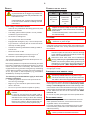
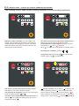
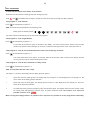
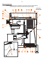
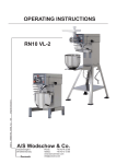
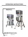
OPERATING INSTRUCTIONS 082015 ORDER NO.: 00011_VL2 GB Translation of the original user manual RN20/VL2 A/S Wodschow & Co. Kirkebjerg Søpark 6 DK-2605 Brøndby Denmark Phone: +45 43 44 22 88 www.bearvarimixer.com [email protected] 2 Contents: General: . ..................................................................................................................................................................... 2 Unpacking: . ..................................................................................................................................................................... 2 Transport:....................................................................................................................................................................... 3 Installation and fixing: ..................................................................................................................................................... 3 Examples of electrical connections:................................................................................................................................. 3 Commissioning:................................................................................................................................................................... 4 Recommended use of the machine:...................................................................................................................................... 4 Technical data:................................................................................................................................................................. 4 Dimension sketches:........................................................................................................................................................... 4 The maximum capacity of the mixer:.................................................................................................................................... 4 Construction of the mixer:................................................................................................................................................ 5 Safety: . ..................................................................................................................................................................... 6 Correct use of tools:....................................................................................................................................................... 6 Cleaning: . ..................................................................................................................................................................... 6 Lubrication and grease types:........................................................................................................................................... 6 Attachment drive:.............................................................................................................................................................. 6 VL2 control panel - survey of various operating situations:............................................................................................. 7 Operation of the mixer:..................................................................................................................................................... 8 The Remix function:........................................................................................................................................................... 9 Change of fixed speeds:.................................................................................................................................................... 9 Reset of timer:.................................................................................................................................................................. 9 Overloading:..................................................................................................................................................................... 9 Procedure in case of overloading:.................................................................................................................................... 9 Recommended max. speeds:................................................................................................................................................ 9 Recommended max. speeds for attachment drive:............................................................................................................... 9 VL-2 control, error codes and possible solutions:........................................................................................................ 10 Test programs:................................................................................................................................................................11 Service instructions:....................................................................................................................................................... 12 Cabling diagram:............................................................................................................................................................. 16 Examples of power connections:..................................................................................................................................... 16 Electrical diagrammes:................................................................................................................................................... 17 General: This manual should be seen as an integral part of the mixer and should be kept by the machine throughout its working life. Before the machine is commissioned, it is important to read these instructions thoroughly, particularly the section on user safety. The manufacturer may update the product manual without updating this copy of the manual. The manufacturer will not be liable for faults caused by: Careless, improper or incorrect use of the mixer Non-standard use (not for the purposes described in the manual) • Incorrect installation • Incorrect power supply to the machine • Failure to comply with maintenance instructions • Modifications to the machine • Spare parts and accessories that are not original or specified for this model • Failure to comply with instructions in this manual In case of faults with the mixer, please contact the supplier. The guarantee does not cover damage caused by misuse, overloading or the user’s failure to comply with the maintenance instructions. In case of complaints, please contact your supplier. Unpacking: The machine should be unpacked and the packaging disposed of according to regulations applicable in the country concerned. Before the mixer is removed from the pallet, check that all parts are present with the machine. • Power cable • Safetyguard • Bowl, whip, beater, hook and Intermediate pieces 3 Transport: Lifting equipment should always be used to move the machine. Allowance should be made for the fact that the machine is ‘top-heavy’. The machine must not be pulled or lifted by the bowl lift handle. When the machine is moved, it should be in a vertical position at all times. Installation and fixing: The ambient temperature around the machine must not exceed 45oC. If the mixer is placed on a table, it must always be bolted into the table top. The bolts fixing the mixer on the pallet can be used for this, no nuts are needed as there are threads in the bottom plate of the mixer (see page 5). If the mixer is placed on a bench stand, it can be placed direct on the floor. Foundation bolts in the floor are recommended. Intermediate pieces can be inserted under the mixer’s feet, if the floor is not completely even. Electrical connection: Users can connect the mixer to the power supply themselves; refer to the section on Electrical connection which must be followed. For the benefit of service staff, it should be clear to see when the mains plug to the mixer has been removed from the socket in the wall. Before the machine is connected to the mains, check that the voltage and frequency printed on the name plate are correct for the installation location. The name plate is placed at the top of the right side of the mixer There is a risk of injury if the machine is not earthed. It must be ensured that the cable used to connect the machine to the mains meets the standard for the country in which the machine is installed. See also Example of electrical connections. The mixer must be earthed. Failure to do so may cause injury. If there is no earth connection, the EMC filter will not work, with the risk of damage to the frequency converter. When the machine is connected, phase + neutral + earth or phase + phase + earth should be used. In both cases, it is important to ensure that the voltage between the two live pins matches the name plate.(See examples below) The machine must only be connected to an earthed mains supply. A plug with two pins plus earth should be used. Alternatively, two wires plus earth from a three-phase supply may be used. The machine should be protected by a differential switch. The mixer is protected by a 10A fuse. The fuse is built into the frequency converter, which is placed in the bottom of the mixer. Examples of electrical connections: Voltage at the installation: 50/60 Hz The machine sign Power: Phases x voltage With neutral Earth Voltage Phases Use Use neutral earth 1 x 220-240V Neutral yes 230V 1 yes yes 2 or 3 x 220-240V - yes 230V 2 - yes 2 or 3 x 380-415V Neutral yes 230V 1 yes yes 2 or 3 x 380-480V - yes 380-480V 2 - yes 2 or 3 x 110-220V Neutral yes 100-110V 1 yes yes 1 x 100-120V Neutral yes 100-110V 1 yes yes 3 x 100-120V - yes 100-110V 2 - yes Remarks Please note that the mixer is able to run without any connection to earth, but this causes a reduced functionality of the EMC-filter due to lack of leakage to earth. Of functional and safety reasons, the machine should be connected to earth!. 4 Commissioning: Bowl, tools and safety guard should be cleaned before use – see section on Cleaning, page 6. Recommended use of the machine: The machine is designed for the manufacture of products that do not trigger any reactions or release substances that may be harmful to the user when in use. The machine must not be used in an explosive atmosphere. The mixer must only be operated by staff who have been trained in the use of the machine according to these instructions. Users must be over 14 years of age. The mixer is designed for commercial use in kitchens, catering outlets and bakeries. The machine may only be used as specified in this manual. Unless the change is recommended by the manufacturer, modifying the machine is prohibited. If the machine is fitted with an attachment drive, only accessories produced or recommended by A/S Wodschow & Co should be attached. Technical data: Gross weight Table model 108 kg Floor model 123 kg Net weight Table model 82 kg Floor model 87 kg kW Volts Amps Variable speed, tool 1,2 kW 230V 8A 98 – 368 rpm Dimension sketches: Dimension sketch for RN10 table model. The maximum capacity of the mixer: Capacities per mix Tool RN20 Egg white Whip 2,4 L Whipped cream Whip 5L Mayonnaise * Whip 16 L Herb butter Beater 10 kg Mashed potatoes * Beater/Whip 12 kg Bread dough (50%AR) ** Hook 10 kg Bread dough (60%AR) Hook 11 kg Ciabatta dough * (70%AR) Hook 12 kg Muffins * Beater 14 kg Layer cake base Whip 5 kg Meatball mix * Beater 15 kg icing Beater 14 kg Doughnut (50%AR) Hook 12,5 kg * Scraper recommended ** Low speed operation is recommended Dimension sketch for RN10 on floor stand. AR = Absorption Ratio (%AR) (Liquid in % of solids) Example: A basic recipe contains 1 kg of solids and 0,5 kg of liquid: This gives AR = 0,5 kg x 100 = 50% 1 kg If for instance it is required to use the maximum capacity of the mixer, the calculated AR = 50% is used for determining the amount of solids and liquid in the dough: If a 20 L mixer is used, and a dough with AR = 50% is to be kneaded, the maximum capacity is = 10 kg. Now the weight of solids in this dough is calculated: Solids = Max. capacity x100 = 10 kg x 100 = 6,7 kg AR + 100 50 + 100 Weight of liquid = 10 kg - 6,7 kg = 3,3 kg Local variations in the characteristics of the ingredients can influence water absorption, volume and baking characteristics, etc. 5 Construction of the mixer: Attachment drive Emergency stop Machine label Arrow indicating the rotation direction of the planetary head Toothed belt Planetary head Motor Bayonet socket Bowl lift Bottom plate Bowl lift arms Screws for fixing on table Nut retaining the bottom plate Standard equipment, as follows: • Bowl –0 l • Hook in stainless steel • Beater in stainless steel • Whip in stainless steel • Safetyguard Optional Equipment • Scraper in stainless steel with blade • Tool rack • Table in stainless steel • Vegetable cutter • Meat mincer 6 Safety: Correct use of tools: The machine is designed for the manufacture of products that do not trigger any reactions or release substances that may be harmful to the user when in use. Users must be over 14 years of age and trained in the use of the machine according to these instructions. User safety is assured as follows: • Tools can only rotate when the safety guard is in place and the bowl is lifted. • The safety guard is made of plastic. It is not possible to attach the guard incorrectly. • No access to rotating tools. • The spread of flour dust is inhibited • Equipped with emergency stop - The tool stops rotating in less than 4 seconds (also for normal shut-down and stop via safety guard). Recommended uses of tool: Whip Beater Hook Cream Cake mix Bread dough Egg whites Buttercream Rye bread Mayonnaise Waffle mix etc. etc. Forcemeat etc. The whip should not be struck against hard objects such as the edge of the bowl. This will shorten the life of the tool because of increasing deformation. To make mashed potato, use the beater and then the standard whip. Cleaning: • Clearance between guard/stand and lifting handle at least 50 mm. • Noise level under 70 dB. • Machine remains stable on a slope of up to 10 o The machine is protected against overvoltage. The machine should be positioned to allow space for normal use and maintenance. Non-ionising radiation is not produced intentionally, but rather technically conditioned by electrical equipment (e.g. electric motors, live power lines or solenoids). The machine is not equipped with strong permanent magnets. By maintaining a safe distance (between the field source and implant) of 30 cm, any impact on active implants (e.g. pacemakers, defibrillators) can likely be prevented. The following recommendations apply to work with powdery ingredients: • Powdery ingredients should not be poured into the bowl from a great height. • Bags of e.g. flour should be opened at the bottom, down in the bowl. • Do not run up to the maximum speed too quickly. There is a risk of injury if the machine is not earthed. It must be ensured that the cable used to connect the machine to the mains meets the standard for the country in which the machine is installed. See also ‘Electrical Connection’. Placing your hands in the bowl while the machine is running may cause physical injury. The machine may only be cleaned by trained staff over 14 years of age. The machine should be cleaned daily after use. It should be wiped with a soft brush and clean water. Sulphonated soaps should be used with care, as they destroy the lubricants in the machine. The machine should never be rinsed with a hose. Aluminium parts should not be used for strongly acidic, alkaline or saline food products, which may attack non-coated aluminium. Aluminium mixer tools must not be washed in strongly alkaline agents (pH between 5.0 and 8.0). Please note that the plastic safety guard may be damaged if it is exposed to high temperatures for a prolonged period. (Max. temperature 60ºC) The soap suppliers may be able to help by recommending the right type of soap. Lubrication and grease types: Lubrication and other servicing may only be carried out by trained staff over 14 years of age. The lid of the mixer may only be removed when the cable to the mains supply has been removed. When repairs are made to the mixer head, the gearwheel and internal gear should be lubricated with Molub Alloy 936SF Heavy or Castrol Grippa 355, but the needle bearings in the mixer head should not be lubricated with this type of grease. If the machine is supplied with an attachment drive, the gear for the attachment drive should be lubricated with ESSO Fibrax EP 370. Do not use any other grease types than those specified above. Attachment drive: The machine may be fitted with an attachment drive into which optional accessories, such as meat mincers and vegetable cutters, can be attached. For further information on the assembly and use of optional accessories, please refer to the manual that comes with the accessory. The machine must be shut down when the accessory is fitted to the attachment drive. 7 VL2 control panel - survey of various operating situations: The following pictures show various operating situations and corresponding explanation: Emergency stop is activated - there is no light in the display. If the red diode at is flashing, the mixer has stopped because the safety circuit has been interrupted, either because the bowl arms have been lowered or the safety guard has been opened. The mixer is connected to power and is ready for start flashing of the green diode at will show that! It is possible to set a start speed by pushing one of the fixed speeds or , before is pushed. When is pushed, the mixer will start in minimum speed. Operating time is stated by pushing or . A program is run by first pushing and thereafter the wanted number, e.g for program No. 1. The mixer is running and a speed has been chosen four diodes on the speed indicator are alight. The speed can be changed by pushing one of the buttons for the four fixed speeds or or . The mixer can be stopped without reset of the timer, by pushing or by opening the safety guard. The mixer is restarted by pushing . has been pushed - yellow diode at is flashing. The mixer is started by pushing . The timer will start again and the speed is running up to the chosen speed. If is pushed, the timer is reset and the mixer will not start, but is ready for start - green diode at will flash (see picture 2). 8 Operation of the mixer: Time up Text field (timer) Time down Fixed speeds Pause Speed indicator REMIX-function Speed down Start/Stop Emergency stop Speed up Before starting the mixer: Indication of operation time: • Put the desired tool into the bowl • Place the bowl in the bowl arms • Turn the tool to lock it into the bayonet fitting. • Attach the safety guard • Raise the bowl to its working position by means of the handle for bowl lift. The maximum operating time is 60 minutes. • The mixer is ready for start Inspection of the ingredients during operation: Before starting the mixer, an operation time for the mixer can be chosen by pushing or . The operating time will be shown in minutes and seconds in the timer field between and . Push to start the mixer. If it is wished to stop the mixer without reducing operation time and speed, push . The mixer will reduce speed and then stop, the operation time will also stop. Push to increase the speed. It is now possible to lower the bowl to check the ingredients. Push to reduce the speed. Raise the bowl and push , and the mixer will start and will increase the speed to the speed chosen before pushing . The operating time will also be continued. Start the mixer: Or push speeds. , , or to choose one of the fixed The speed indicator below the fields mixing speed of the tool. to shows the Stop the machine: Four fixed speeds: For quick choice of speed, use the fields If the bowl is lowered while the mixer is stopped, the operating must be pushed to restart the mixer. time is reset, and to . Field corresponds lowest speed, aprox. 98 RPM. Field corresponds aprox. 172 RPM. Field corresponds aprox. 267 RPM. Field corresponds maximum speed, aprox. 365 RPM. It is possible to change the fixed speeds - see the paragraph „Change of fixed speeds“. To stop the machine: • Press . Running time will be reset. • Press . Running time will not be reset. • Press the emergency stop - the running time will be reset. • Remove the safety guard - the running time will be reset. • Lower the bowl - the running time will be reset. In all cases the mixer can be restarted by pressing It will start at the lowest speed. . 9 The Remix function: Overloading: The special Remix-function is a shortcut to programming of recipes. While the mixer is operated, all commands are stored, and when a recipe is finished and is pushed, it is possible to store the entire recipe under a program number. The mixer must not be overloaded. Possible overload situations: • Working with excessively tough and heavy dough • Mixer tool exceeding the recommended speed • There are four program numbers. • A program cannot be deleted, but can be replaced. • The programs are not deleted in case of no power. How to store a program: • Wrong mixer tool being used. Larger lumps of fat or chilled ingredients must be reduced before they are placed in the bowl. Prolonged overloading will cause the frequency converter to stop the machine. • First push • Run the entire recipe including pauses and changes of speed. • Push • Store the program as program No. 1 by pushing first and then also continuously, until the total length of the program is shown in the timer field. The timer field will thereafter flash „P1“ three times. . . How to run a program: • First a short push on and then on . Now „P1“ appears in the timer field and immediately thereafter the total length of the program will be shown. The program is run by pushing . • If the speed or the time is changed, or is pushed when running a program, the program will be left and the mixer must be run manually. • It is possible to remove the safety guard while running a program. When the safety guard is reattached, the program can be resumed by pushing . • If the program is containing a pause, the mixer will stop and at the same time an acoustic signal is heard. When the operator wants to restart the mixer, push and the program will be resumed. , or will be displayed in the timer field; the speed will not be reduced, but the mixer will stop and the display will change to . Follow the description under Procedure in case of overloading. Procedure in case of overloading: Remove the cause of the overloading, e.g. empty the bowl. • Push emergency stop • Release emergency stop. • Start the mixer by pushing . Recommended max. speeds: Recommended max. speeds (factory setting). Change of fixed speeds: For the fields and it is possible to change the speed for future mixing jobs. Push or to adjust the speed up or down. Recommended max. speeds for attachment drive: If required to store the adjusted speed, push or until two beeps are heard and the diodes of the speed indicator are flashing. The adjusted speed has now been stored in the memory. To return to the factory settings for button and and simultaneously, until a beep is heard. push Reset of timer: The timer can be reset by simultaneously pushing and . If the timer is reset while the mixer is running, the mixer will stop. Recommended max. speeds for attachment drive. 10 VL-2 control, error codes and possible solutions: Error codes and possible solutions: The VL2 control will in case of certain errors show an error code in the display: Too high temperature in the frequency converter. Solution: Switch off the mixer and let it cool down. Wrong voltage of power supply. Solution: Compare the voltage indicated on the machine label with the power supply. The motor has been constantly overloaded for a long period of time. The load has been between 100 - 150% of maximum load. The overload is typically found in case of mixing/whipping tasks with constant load. Solution: Switch off the mixer and reduce the quantity of ingredients in the bowl. Finish the work in a lower speed. Low voltage is periodically noted in the power supply. Solution: The machine’s power supply must be inspected by a technician. Too high temperature in motor. Solution: Switch off the mixer and let it cool down. Reduce the quantity of ingredients in the bowl. Finish the work in a lower speed. Communication break. Cable Connection between the control panel and frequency converter is defective. Solution: Make sure the cable is seated properly in the connectors, replace the cable if it is defective. , and The mixer has been overloaded from work with heavy dough or the like Solution: Reduce the quantity of ingredients in the bowl. if possible, the product may be decomposed into smaller pieces or diluted before the mixer is restarted. Finish the work in a lower speed. Errors that do not cause an error code in the display: The mixer does not start when is pushed, but the timer is counting as normal. There is no error code in the display. Solution: The frequency converter is defective and must be exchanged. See “Service Instructions” page 10 for access to the frequency converter. The mixer does not start when is pushed. There is no error code in the display. Solution: Activate emergency stop and release it again. Now two different codes should be shown in the display. The first code is a small square in top of the first cipher of the display followed by a version code, this is the software version of the control panel. The next code is a small square in bottom of the first cipher of the display followed by a version code, this is the software version of the frequency converter. If no codes are shown or if only the first code is shown, the error can derive from either a defective communication cable between the control panel and the frequency converter, or a defective frequency converter. The mixer is totally “dead”, no light in the control panel. Solution: Check the connection to power supply, if connection and power supply are OK, the error is either a defective communication cable between the control panel and the frequency converter, or a defective fuse in the frequency converter. See “Service Instructions” page 10 for access to the frequency converter. 11 Test programs: To enter the test mode of the mixer, do as follows: Raise the bowl and close the safety guard, push emergency stop. Hold and and release the emergency stop at the same time. Now go through four test programs: Test program 1: Test of fields. Press to activate test program no. 1 OBS. The fields must be activated in the following order: Briefly push the following fields – – – – – – – – – – . The mixer will now automatically run the next three test programs. Test program 2: Test of light diodes. Press to activate test program no. 2 For the first 20 seconds the cipher 2 will flash in the display - the remix memory will be erased. Then the light diodes in the speed indicator will light up one by one, while the other light diodes of the control panel are on. Test program 3: Test of current measurement circuit in the frequency converter. Press to activate test program no. 3 The motor starts and runs for approx. 20 seconds. After the 20 seconds a text is shown in the display, this text will vary and can only be used for testing the function. Test program 4: Test of micro switches in safety circuit. Press to activate test program no. 4 OBS. It is important that the order is kept. The cipher 1 is shown in the display until the safety guard is opened. • • • Open and close the safety guard. The display shall now change to 2. If the display does not change to 2, the micro switch at the safety guard is defective. Raise and lower the bowl again. The display shall now show 3. If the display does not change to 3, the micro switch at the bowl lift is defective. Conclude the test by pushing emergency stop and release it again. The display shall now show version codes for control panel and frequency converter resp., as earlier mentioned under “VL2 control, error codes and possible solutions, error . When running the testprogrammes, no specific order is required. It is possible to run the programmes individually 12 Service instructions: Before a possible repair or adjustment, the power must be switched off by dismantling the connection cable from the power supply. 9 16 1 15 12 11 18 Cable bundle stuck to motor base with strips. 14 13 10 4 3 5 6 2 7 8 Cable bundle 17 19 20 20 22 27 20 21 23 13 1 The lid of the mixer shall be removed and the plastic cover (2) shall be loosened by removing the 2 screws (3). 4 The control panel is removed by first removing the plastic ring (7) and the finger screw on the attachment drive, and then loosening the 2 screws (5). 6 The attachment drive is taken out by removing the finger screw and removing the plastic ring (7), the control panel (4) and the 4 bolts (8). 9 The display print is removed by removing the 2 screws (10). 11 The toothed belt is exchanged in the following way: a) Remove the lid of the mixer (1) and the plastic cover (2). b) Loosen the four nuts (12) holding the motor base (13). By pushing the base towards the front of the mixer, the belt is slackened and can be lifted off the motor pulley (14) and the planetary head pulley (15). c) The new toothed belt is mounted by pushing it downwards over the two pulleys. d)The toothed belt is tightened by pushing the motor base towards the back of the mixer. Use a big screwdriver or the like to hold the base in its place, while the nuts are mounted and tightened. 14 + 15 The pulleys are taken off in the following way: a) Remove the lid of the mixer (1), the plastic cover (2) and the toothed belt (11). b)Screw the pointed screws (16) out of the pulley. The pulley can now be lifted off the locking ring. c) The locking rings are loosened from the shafts by screwing one of the pointed screws approx. one turn down in the middle centre hole. The locking ring can be removed. 16 17 15 The motor can be taken out in the following way: a) The power must be switched off, or the connecting cable dismantled from the power supply. b) Take off the lid of the mixer (1), the plastic cover (2), the toothed belt (11) and the motor pulley (14). d)Remove the four nuts (12) and cut the strip holding the cable bundle on the back of the motor base. The motor base (13) with motor (17) can now be lifted out above the mixer. e) Motor base and motor can be separated by removing the four screws (18). 19 The legs of the mixer are taken off by removing the screws (20). 21 The frequency converter is taken out in the following way: 26 a) Remove the lid of the mixer (1). b)Cut the strips holding the cable bundle to the motor base (13). c) Remove the screw (22) in the bottom of the mixer. d)The frequency converter including the mounting plate (23) can now be tilted/lifted out of the bottom of the mixer. e) Dismantle all plugs for the frequency converter. f) The cover box (24) above the frequency converter (21) can be removed by loosening the screws (25). 26 The fuse is exchanged by taking out the frequency converter including mounting plate (23) and then removing the cover box (24). 27 The bottom plate is taken off by removing the legs of the mixer (19), and the 2 nuts (28). 24 25 22 27 23 21 14 30 1 11 4 6 31 35 33 32 34 29 29 The planetary head is taken off in the following way: a) Take off the lid of the mixer (1), control panel (4), attachment drive (6), and toothed belt (11). b) Take out the screws (30) c) The plastic ring (31) can be taken off by hitting it slightly against the front edge and thereafter pressing a screwdriver in between the plastic ring and the metal plate at the top of the plastic ring. d) Take off the rubber packing (32). e) The stainless steel head cap (33) can now be taken off by hitting the front edge slightly with a plastic hammer, turning the planetary head 1800, and hitting again slightly on the front edge. f) If only the bottom part of the planetary head is to be repaired, follow the instructions from c) to e). Hereafter the planetary head can be disassembled by taking out the 3 bolts (34). g) By loosening and removing the 4 bolts (35) the planetary head can be lowered. Mounting of the planetary head to be in reverse order. 15 35 Micro switch for bowl lift can be exchanged in the following way: a) Take off the lid of the mixer (1) and the plastic cover (2). b) Remove the base for motor (13) with the motor (17). c) Access is now free to the bowl lift micro (35), which can be exchanged by removing the two wires and loosening the screws (36). d) The new micro switch is mounted by following the instructions in reverse order. No adjustment is needed. 35 36 39 Micro switch for safety guard can be exchanged in the following way: a) Remove the lid of the mixer (1) and the operating panel (7). b) Screw out the pointed screw (37), and the cam disc (38) can be removed. c) The fitting with micro switch (39) can now be removed, and the micro can be exchanged by removing the screws (40). It might be necessary to loosen the screws (41) before the fitting can be taken out. d) The new micro switch is to be screwed on to the fitting, and the fitting to be placed in the machine. It is important that the two screws (41) are adjusted so that the fitting is horizontal. 41 37 38 39 40 - Neutral - 2 or 3 x 380-415V 2 or 3 x 380-480V Neutral 1 x 220-240V 2 or 3 x 220-240V With neutral Power: Phases x voltage yes yes yes yes Earth Voltage at the installation: 50/60 Hz 380-480V 230V 230V 230V Voltage Examples of power connections: RN20-194.28M rev 02 RN20-194.27M rev 02 RN20-194.26M rev 03 RN20-194.25M rev 01 RN20-194.39M rev 00 2 1 2 1 Phases - yes - yes yes yes yes yes Use Use neutral earth Remarks Of functional and safety reasons, the machine should be connected to earth! Please note that the mixer is able to run without any connection to earth, but this causes a reduced functionality of the EMC-filter due to lack of leakage to earth. The machine label RN20-194.17M rev 02 RN20-194.16M rev 01 RN20-194.15M rev 01 RN20-194.19M rev 00 RN20-194.38M rev 00 RN20-194.37M rev 00 RN20-194.29M rev 00 16 Cabling diagram: Rood Blauw Wit Geel 5 4 3 2 1 5 4 3 2 1 Rood Blauw Wit Geel 1 2 3 4 5 1 2 3 4 5 beschermkap Rood Blauw Wit Geel Groen Zwart 1 - Rood 2 - Blauw 3 - Wit 4 - Geel 5 - Groen 6 - Zwart 6 3 5 2 4 1 CE/bekken 6 3 5 2 4 1 6 - Bruin (T2) 5 - Rood (bekken) 4 - Oranje (beschermkap) 3 - Bruin (T1) 2 - Rood (bekken) 1 - Oranje (beschermkap) Oranje Oranje 6 Oranje Oranje 6 Rood Rood Groen Rood Rood Zwart Bruin Bruin 6 Bruin Bruin 6 4 - Zwart (M1) 1 1 2 2 3 3 4 - Zwart 3 - Blauw 2 - Blauw 1 - Zwart 4 4 1 - Bruin (L) 2 - Blauw (N) Noodstop 3 - Geel/Groen (PE) 1 - Geel/Groen, (PE) 2 - Bruin (M3) 3 - Blauw (M2) Zwart Zwart Groen Blauw Blauw Zwart Blauw Blauw frequentieomvormer Zwart Zwart bedieningspaneel Geel/Groen Bruin Blauw Zwart 1 2 3 1 2 3 1 2 3 4 Bruin Zwart Geel/Groen 1 2 3 1 2 3 4 Geel/Groen Bruin Blauw Zwart 1 2 1 2 Bruin Bruin Geel/Groen Wit Rood Zwart (getoond 400V) Voor spanning x>240V Oranje 460V purper 480-500V Groen 420-440V Rood 380-420V Zwart Geel/Groen 4 1 2 3 4 1 2 3 2 1 1 3 2 3 T=145o Motor 17 Electrical diagrammes: 18 Indhold af CE Overensstemmelseserklæring, (Maskindirektivet, 2006/42/EC, Bilag II, del A) Contents of the EC Declaration of conformity for machinery, (Machinery Directive 2006/42/EC, Annex II., sub. A) Inhalt der EG-Konformitätserklärung für Maschinen, (Richtlinie 2006/42/EG, Anhang II, sub A) Contenu de la Déclaration CE de conformité d’une machine, (Directive Machine 2006/42/CE, Annexe II.A) Inhoud van de EG-verklaring van overeenstemming voor machines, (Richtlijn 2006/42/EC, Bijlage II, onder A) Contenido de la declaración "CE" de conformidad sobre máquinas, (Directiva 2006/42/EC, Anexo II, sub A) Fabrikant; Manufacturer; Hersteller; Fabricant; Fabrikant; Fabricante: Adresse; Address; Adresse; Adresse; Adres; Dirección: DK GB DE FR NL ES A/S Wodschow & Co. ………………………………………………………………….…… Kirkebjerg Søpark 6, DK-2605 Brøndby, Denmark ………………………………………………………………………. Navn og adresse på den person, som er bemyndiget til at udarbejde teknisk dossier Name and address of the person authorised to compile the technical file Name und Anschrift der Person, die bevollmächtigt ist, die technischen Unterlagen zusammenzustellen Nom et adresse de la personne autorisée à constituer le dossier technique naam en adres van degene die gemachtigd is het technisch dossier samen te stellen nombre y dirección de la persona facultada para elaborar el expediente técnico Navn; Name; Name; Nom; Naam; Nombre: Adresse; Address; Adresse; Adresse; Adres; Dirección: Sted, dato; Place, date; Ort, Datum; Lieu, date ; Plaats, datum ; Place, Fecha: Kim Jensen ………………………………………………………………………. Kirkebjerg Søpark 6, DK-2605 Brøndby, Denmark ......................................................................... Brøndby, 15-12-2009 ........................................................................ Erklærer hermed at denne røremaskine Herewith we declare that this planetary mixer Erklärt hiermit, dass diese Rührmaschine Déclare que le batteur-mélangeur ci-dessous Verklaart hiermede dat Menger Declaramos que el producto batidora er i overensstemmelse med relevante bestemmelser i Maskindirektivet (Direktiv 2006/42/EC) is in conformity with the relevant provisions of the Machinery Directive (2006/42/EC) konform ist mit den Bestimmungen der EG-Maschinenrichtlinie (Direktiv 2006/42/EG) Satisfait à l’ensemble des dispositions pertinentes de la Directive Machines (2006/42/CE) voldoet aan de bepalingen van de Machinerichtlijn (Richtlijn 2006/42/EC) corresponde a las exigencias básicas de la Directiva sobre Máquinas (Directiva 2006/42/EC) er i overensstemmelse med følgende andre CE-direktiver is in conformity with the provisions of the following other EC-Directives konform ist mit den Bestimmungen folgender weiterer EG-Richtlinien Est conforme aux dispositions des Directives Européennes suivantes voldoet aan de bepalingen van de volgende andere EG-richtlijnen está en conformidad con las exigencias de las siguientes directivas de la CE 2004/108/EC ……………………………………………………………………………………………………………………………………... Endvidere erklæres det And furthermore, we declare that Und dass Et déclare par ailleurs que En dat Además declaramos que at de følgende (dele af) harmoniserede standarder, er blevet anvendt the following (parts/clauses of) European harmonised standards have been used folgende harmonisierte Normen (oder Teile/Klauseln hieraus) zur Anwendung gelangten Les (parties/articles des) normes européennes harmonisées suivantes ont été utilisées de volgende (onderdelen/bepalingen van) geharmoniseerde normen/nationale normen zijn toegepast las siguientes normas armonizadas y normas nacionales (o partes de ellas) fueron aplicadas EN454:2000 ; EN60204-1:2006; EN12100-1:2005 ……………………………………………………………………………………………………………………………………... EN12100-2:2005; EN61000-6-1:2007; EN61000-6-3:2007 ……………………………………………………………………………………………………………………………………... 19 Innehåll i EG-försäkran om maskinens överensstämmelse, (Maskindirektivet 2006/42/EG, bilaga 2, A) Contenuto della dichiarazione CE di conformità per macchine, (Direttiva 2006/42/CE, Allegato II, parte A) Sisukord EÜ masina vastavusdeklaratsioon , (Masinadirektiiv 2006/42/EÜ, lisa II, punkt A) Treść Deklaracja zgodności WE dla maszyn (Dyrektywa maszynowa 2006/42/WE, Załącznik II, pkt A) Sisältö EY-vaatimustenmukaisuusvakuutus koneesta (Konedirektiivi 2006/42/EY, Liite II A) Tillverkare; Fabbricante; Tootja; Producent; Valmistaja: Adress; Indirizzo; Aadress; Adres; Osoite: SE IT EE PL FI A/S Wodschow & Co. ………………………………………………………………….…… Kirkebjerg Søpark 6, DK-2605 Brøndby, Denmark ………………………………………………………………………. Namn och adress till den person som är behörig att ställa samman den tekniska dokumentationen: Nome e indirizzo della persona autorizzata a costituire il fascicolo tecnico Tehnilise kausta volitatud koostaja nimi ja aadress Imię i nazwisko oraz adres osoby upoważnionej do przygotowania dokumentacji technicznej Henkilön nimi ja osoite, joka on valtuutettu kokoamaan teknisen tiedoston Namn; Nome e cognome; Nimi; Imię i nazwisko; Nimi: Adress; Indirizzo; Aadress; Adres; Osoite: Ort och datum; Luogo e data; Koht, kuupäev; Miejscowość, data; Paikka, aika: Kim Jensen ………………………………………………………………………. Kirkebjerg Søpark 6, DK-2605 Brøndby, Denmark ......................................................................... Brøndby, 15-12-2009 ........................................................................ Försäkrar härmed att denna blandningsmaskin Con la presente si dichiara che questo mixer planetaria Deklareerime käesolevaga, et Planetaarmikseri Niniejszym oświadczamy, że mikser planetarny vakuuttaa, että tämä mikseri tyyppi överensstämmer med tillämpliga bestämmelser i maskindirektivet (2006/42/EG) is è conforme alle disposizioni della Direttiva Macchine (Direttiva 2006/42/CE) vastab kehtivatele masinadirektiivi (2006/42/EÜ) nõuetele spełnia wymagania odpowiednich przepisów dyrektywy maszynowej (2006/42/WE) on konedirektiivin (2006/42/EY) asiaankuuluvien säännösten mukainen överensstämmer med bestämmelser i följande andra EG-direktiv è conforme alle disposizioni delle seguenti altre direttive CE vastab järgmiste EÜ direktiivide nõuetele spełnia wymagania przepisów innych dyrektyw WE on seuraavien muiden EY-direktiivien säännösten mukainen 2004/108/EC ……………………………………………………………………………………………………………………………………... Vi försäkrar dessutom att e che Lisaks ülaltoodule deklareerime, et Ponadto oświadczamy, że ja lisäksi vakuuttaa, että följande (delar/paragrafer av) europeiska harmoniserade standarder har använts sono state applicate le seguenti (parti/clausole di) norme armonizzate kasutatud on järgmisi Euroopa harmoniseeritud standardeid (või nende osi/nõudeid) zastosowano następujące części/klauzule zharmonizowanych norm europejskich seuraavia eurooppalaisia yhdenmukaistettuja standardeja (tai niiden osia/kohtia) on sovellettu EN454:2000 ; EN60204-1:2006; EN12100-1:2005 ……………………………………………………………………………………………………………………………………... EN12100-2:2005; EN61000-6-1:2007; EN61000-6-3:2007 ……………………………………………………………………………………………………………………………………... 20