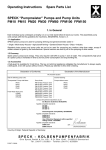
1
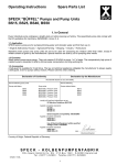
Operating Instructions, Spare Parts List
SPECK BÜFFEL Pumps
S75, S100, S150, S450, S456 (S200, S300)
1. In General
Every individual pump undergoes a lengthy test-run before leaving our factory.
1.1 Areas of Applications
SPECK piston pumps are for pumping drinking water and waste water and find their use in:
• Agriculture • Ships • Industry • Horticulture
Should the pumps be used for pumping other media than water, written consent must be given by the manufacturer.
Special versions are built by us for pumping other fluids.
1.2 Economical Features
SPECK piston pumps save energy. The compartively high price of a piston pump is rewarded in time by its low power
consumption and long working life.
1.3 Accessories
A belt guard is available for V-belt drive. The law on technical appliances obligates the manufacturer to supply a belt
guard, even for pumps without motors. Please note this when ordering.
Declaration of Conformity
Declaration by the Manufacturer
We herewith declare on our own liability
that the following pump units:
that the following
Pumps with Motor:
Pumps without Motor:
S75
S100
S150
S450
S456
S75
S100
S150
S450
S456
Comply with the following relevant stipulations:
EU Machinery Guidelines 98/37/EU
Applied harmonized standards:
EN 809
EN 292 T1
EN 292 T2
Electromagnetic Compatibility: 89/336/EWG
Applied harmonized standards:
EN50 081-1
EN50 082-2
Use of Electrical Equipment within specified
Voltage Limits: 73/23/EU
Applied harmonized standards:
EN60 335-1
EN60 335-2-51
p.p. ........................................
(Technical Director)
Country of Origin: Federal Republic of Germany
S P E C K - K O L B E N P U M P E N FA B R I K
Otto Speck GmbH & Co. KG · P.O. Box 1240 · D-82523 Geretsried
Tel. (08171) 62930 · Fax (08171) 629399
s75-s456-b-e 1007
1
2. Safety
The Operating instructions give basic information which must be observed during installation, operation and
maintenance of the pump. It is therefore imperative that the operating instructions be read by the fitter and
personnel/operator prior to assembly and operation. This manual must always be on hand at the site of the pump unit.
It is not only the general safety instructions contained under this main heading ‘Safety’ that are to be observed, but
also the specific information provided under the other main headings.
2.1 Identification of Symbols shown in the operating instructions
The safety directions given in these operating instructions, which when not observed can cause danger to persons,
are identified by the following symbol:
or where electrical safety is involved, by
safety sign as per DIN 4844-W9
safety sign as per DIN 4844-W8
Safety measures whose non-observance can cause damage to the machine are marked:
It is imperative that signs affixed to the machine such as:
• the arrow indicating the directions of rotation
• symbols indicating fluid connections
be observed and are kept legible.
2.2 Qualification and Training of the Operating Personnel
The personnel responsible for operation, maintenance, inspection and assembly must be adequately qualified. Scope
of reponsibility and supervision of the personnel must be exactly defined by the plant operator. If the staff does not
have the necessary knowledge, they must be trained and instructed, which may be carried out by the machine
manufacturer or supplier on behalf of the plant operator. Furthermore, the plant operator is to make sure that the
contents of the operating instructions are fully understood by the personnel.
2.3 Hazards in the Event of Non-Compliance with the Safety Instructions
Non-observance of the safety instructions may cause a risk to the personnel as well as to the environment and the
machine, and may result in a loss of any right to claim damages.
For example, non-compliance can involve the following dangers:
•
•
•
•
Failure of important functions of the machine/pump unit
Failure of specified procedures for maintenance and repair
Exposure of people to electrical, mechanical and chemical hazards
Endangering the environment owing to hazardous substances being released
2.4 Safety at Work
The safety instructions contained in this manual, the relevant national accident prevention regulations and any other
service and safety instructions given by the plant operator are to be observed.
2.5 Safety Instructions relating to Operation
• If hot or cold machine components involve hazards, they must be guarded against accidental contact
• Guards for moving parts (e.g. coupling) must not be removed from the machine while in operation
• Any leakage of hazardous (e.g. explosive, toxic, hot) fluids (e.g. from the shaft seal) must be drained away to
prevent any risk to persons or the environment. Statutory regulations are to be complied with.
• Electrical danger must be prevented (details can be obtained from the German Electrical Engineering Association
and from local power stations, for example)
2
2.6 Safety Instructions for Maintenance, Inspection and Assembly Work
It shall be the plant operator’s responsibility to ensure that all maintenance, inspection and assembly work is carried
out by authorized and qualified personnel who have adequately familiarized themselves with the subject matter by
studying this manual in detail.
Any work on the machine must only be carried out when it is at a standstill.
Pumps and pump units that convey hazardous media must be decontaminated.
On completion of work, all safety and protective devices must be put back and made operative again.
Prior to restarting the machine, the instructions listed under ‘Operation’ are to be observed.
2.7 Unauthorized Alterations and Spare Parts
Any modification to the machine may only be made after consultation with the manufacturer. Using original spare parts
and accessories authorized by the manufacturer is in the interest of safety. Use of other parts may exempt the
manufacturer from any liability.
2.8 Unauthorized Modes of Operation
The reliability of the machine delivered will only be guaranteed if it is used in the manner intended which is described
under the heading ’In General’ of this manual. The limit values specified in the data sheet must under no
circumstances be exceeded.
Norms and Other Data
DIN 4844 Part 1
Safety descriptions and safety signs W8 supplement sheet 13
DIN 4844 Part 1
Safety descriptions and safety signs W9 supplement sheet 14
3. Transport and Storage
Storage in a humid environment or where temperatures are below zero is to be avoided. The storage room should be
airy as moisture can damage the motor and thus void the warranty.
Pumps are packed for transportation in cardboard boxes or on pallets. When unpacking, check for any damage.
4. Description
4.1 Büffel Pumps
SPECK piston pumps of the Büffel series have a thoroughly proven double-helical precision gear of unsurpassed
working quietness and service life.
When turned in the correct direction, the gear is lubricated by an oil-dip with bath flooded crosshead. Suction and
discharge connections are on the valve casing and are interchangeable.
The valve casing, air chamber, stuffing box casing and cylinder cover are of grey cast iron (GG20).
The brass suction and discharge valves (2 of each) are made easily accessible by removing the air chamber. The
suction/discharge line does not have to be removed.
The conrod is of solid bronze (G-CuAl10Ni).
The brass cylinder sleeve can be removed via set-screws.
The duo piston is of NBR rubber.
Teflon-impregnated packing rings are used to seal the piston rod in the stuffing box.
4.2 Büffel Pump with Vertical Tank (Pump Unit)
Pump units with vertical tanks are set up by a fitter at the site of installation (see section 5.3). The air volume control
unit installed in the pressure tank of the unit automatically ensures the correct ratio between the water amount and the
necessary air cushion. When the tank is approx. 2/3 full, the valve of the air volume control unit, activated by the float,
opens and the pump begins conveying both air and water into the tank.
A suction head of approx. 4-6 m is necessary so that the pump can draw in air in the proper manner. This rule applies
for pressure tanks with a maximum volume of 750 l or less. Larger tanks should be fed air via a separate source (e.g.
through a compressor, see section 5.3).
When water leaves the tank, the pressure in the tank drops. Eventually the pressure sinks to the automatic switch-on
point which then activates the pressure switch to turn on the motor/pump. The tank is then refilled until the switch-off
level is attained. This procedure repeats itself every time the minimium water amount is reached.
4.3 Adjusted Values of the Pressure Switch
Pump Unit, 4 bar:
Switch-On Pressure: 2 bar
Switch-Off Pressure: 3,5 bar
Pump Unit, 6 bar:
Switch-On Pressure: 3 bar
Switch-Off Pressure: 5,5 bar
3
4.4 Safety Valve
The Büffel pump series S75, S100, S150, S450, S456 (S200, S300) do not have a built-in safety valve. Therefore a
safety valve has to be installed into the discharge line as per the below table or as per the stipulations of the plant
operator. The valve manufacturer can also be consulted with regard to the correct size of the safety valve.
Safety Valve Table:
Pump Model:
Minimum Size :
S75
S100
S150
S200
S300
S450/S456
G1 1/2
G2
G2 1/2
G2 ½ - 3
G3-4
G4
5. Set-Up and Installation (to be done by qualified persons only)
5.1 Location of Pump
The room must be free of frost and dry. It should also be well aired to prevent undesirable moisture
forming on the unit. Moisture damages the motor.
To protect against accidents, each pump must be equipped with a belt-guard which conforms to trade
union and/or general safety rules.
5.2 Büffel Pump
Single Büffel pumps are screwed onto a small brick or concrete base and secured with foundation bolts.
Do not, however, connect the base directly to the wall.
No particular foundation is required for vertical tanks. Particularly quiet operation is achieved by mounting
the piston pump onto anti-vibration material and inserting rubber joints into the suction and discharge
lines. The pump must be accessible from all sides so that maintenance can be carried out properly.
5.3 Büffel Pump with Vertical Tank (Pump Unit)
Pump units with vertical tanks are set up at the site of installation by a fitter. Do not forget that an air
volume control unit for tanks with a max. volume of 750 l or less can also be fitted when setting up units
with vertical tanks. We recommend that tanks over 1,000 in volume litres be fed air via a separate air
source (such as a small compressor, for example).
5.4 Suction Line for Büffel Pumps and Pump Units
Perfect functioning of the pump depends largely on a correctly chosen and well layed-out suction line. In
order to prevent air pockets, the suction line should rise gradually from the well to the pump, or should at
least be layed horizontally. It must be absolutely leakproof and its inner diameter has to be at least as
large as the connection on the pump. Only bows are to be used, no elbows. It is advisable to install a foot
valve – or in the case of a closed filter well, an intermediate valve. If suction lines are longer than 30 m, a
suction air chamber is to be installed directly in front of the pump.
Suction Air Chamber Table:
Pump Output
Suction Air Chamber Volume
Litre/h
Litre
5000
10000
20000
30000
40000
45000
20
50
100
200
300
300
5.5 Suction Head
The total measured suction head which is the height between the water level and the pump plus loss of friction
in the pipe and possible filter resistance, is not to exceed 7.5 m, not forgetting that in dry seasons the water
level in the well may be lower than usual.
In the case of short suction lines or a suction head of below 2 m, or if booster input pressure is present, a shutoff valve must be installed (not a tilted seat valve) in suction line directly in front of the pump. This shut-off
valve can be adjusted with greater accuracy to the required suction head, ensuring the avoidance of water
hammer.
4
5.6 Intake Pressure – Pump Unit as Booster Set
If the inlet pressure is more than 0.3 bar (3 m), it is advisable to install pressure-free feed tank with float
valve. If this is not possible, a shut-off regulator valve must be installed in the feed line under all
circumstances. A vacuum of between 4 – 6 m is required for the the automatic air volume control unit to
function properly. If the pump hammers, install a suction air chamber into the feed line (section 5.4). A
shut-off valve in the suction line is an absolute necessity so that the suction line can be closed for
maintenance work to the pump.
5.7 Discharge Line – for Büffel Pumps and Pump Units
If possible, the discharge line should rise gradually upwards from the pump to the tank or at least be
horizontal. Use curved joints only; elbow fittings are admissible only after the tank. A shut-off valve must
under all circumstances be installed between the pump and tank so that the discharge line can be closed
for maintenance work to the pump. A kick-back valve is unnecessary - it only causes noise.
Correct Sequence of Installation:
Pump – Diaphragm Compensator – Safety Valve – Shut-Off Valve – Pressure Tank or
Overhead Tank
- see installation plan on page 10
If discharge lines are longer than 30 m, an air chamber is to be installed to damp pulsation
Pump Output
Size of Air Chamber
Litre/h
Litre
5000
10000
20000
30000
40000
45000
20
100
150
300
500
500
5.8 Interchanging Suction and Discharge Connections
The suction and discharge sides of SPECK Büffel pumps can be interchanged by converting the suction and
discharge valves which often simplifies installation of the suction and discharge line.
Interchanging the valves is quite simple:
Remove the air chamber (5). Screw off the two fixing screws (hexagon nuts 13a) and take out the valve
bridges (14). The valves (11 and 12) are now exposed and can be interchanged. When fitting the valves,
make sure that the valve seat seals (11x and 12x) sit correctly on the sealing surface.
Starting torque of
holding screw:
S75: 65Nm (M14)
S100: 85Nm (M16)
S150: 100Nm (M16)
S456: 130Nm (M20)
Abb. 114
5
6. Operation
6.1 To Fill Pump with Oil
Fill the crankcase with an SAE30 quality oil by pouring it through the opening (28) and over the crosshead
(23).
Oil Quantity:
S75
S100
S200
S150
S300
S450/S456
1.5 Ltr. 3.0 Ltr. 2x3.0 Ltr. 6.0 Ltr. 2x6.0 Ltr.
6.0 Ltr.
6.2 To Fill Pump with Water
Fill up the pump head with water by pouring the water through the filler plug (33). At the same time, turn the
pump V-belt pulley (18) manually in the direction of the arrow. In the case of long suction lines, fill right up to
the foot valve/intermediate valve (see 5.4).
6.3 Motor Alignment and Electrical Connection
Using a ruler, make sure that the pump pulley and motor pulley (18 & 18b) are in line with each other. The
motor could have been shifted during transport and if the pulleys do not align precisely, the belt will wear
out quickly.
Electrical connection is to be carried out by qualified persons only
The electric motor must be connected as per the circuit diagram which can be found in the terminal box of
the electric motor. Motors up to 1.5 kW in power can be started directly with the pressure switch. Motors
above 1.5 kW in power must be started with a star-delta switch and a relay contactor.
A centrifugal clutch pulley is absolutely necessary to ensure smooth starting and to prevent excessive
current peaks.
The pump/motor must be guarded by a correctly adjusted protective motor switch.
6.4 Fittings
Open shut-off fittings and taps in the discharge line after the tank so that air in the pipe system can
escape.
6.5 Switching On The Motor
Check the direction of rotation (see arrows on the drive casing). The correct direction of rotation is achieved by
exchanging any two lead wires. The shut-off fitting is to be closed again only when: 1. water has begun being
pumped; 2. when the suction line and pump are vented and 3. when water exits the tap. Depending on the
size of the tank, it takes between 5-15 minutes until the tank is full and the pressure switch switches off at
either 3.5 bar or 5.5 bar.
6.6 To Let Water Out
Turn the tap on and let water out. The pressure drops eventually to 2 or 3 bar respectively and the pump
switches on automatically again. Only a few air bubbles should now be in the discharge line, otherwise
there is reason to believe that the suction line and/or pump are not correctly sealed. The mentioned slow
decrease in pressure does not apply to units with an overhead tank or to bilge pumps on ships.
6.7 On and Off Switching Pressure
(for 4 and 6 bar units)
The Büffel pump and pressure tank are approved for a maximum pressure of 4 or 6 bar. Consequently
the pressure switch must only be adjusted to a maximum switch-off pressure of 3.5 bar / 5.5 bar,
otherwise the safety valve will be activated.
To readjust the switch-on / switch-off pressure, see the included instructions for the pressure switch.
Switching Stages:
4 bar Pump Unit:
6 bar Pump Unit:
Switch-On Pressure
Switch-Off Pressure
2 bar
3,5 bar
Switch-On Pressure
Switch-Off Pressure
3 bar
5,5 bar
6
7. Service and Maintenance
7.1 Lubrication
The gear is lubricated automatically provided the pump revolves in the correct direction. The oil level
should be checked every 3 months, and topped up if necessary until oil can be seen through the indicator
glass (24). First oil change after 1 month of operation and then every year thereafter, or every 6 months if
the pump is running continuously. This is done by unscrewing the oil indicator (24) or drain screw (16)
and draining the old oil. Clean out the crankcase (by removing gear cover [2]) and refill with new oil as
described under section 6.1.
7.2 Stuffing Box
The compact stuffing box is made up of Teflon-impregnated packing rings and a grooved seal ring and
requires partically no maintenance at all. The stuffing box must not run dry. Single isolated drops serve to
lubricate and cool it. Should the stuffing box continuously drip, tighten the stuffing box nut (6a) carefully
by approx. ¼ to max. ½ turn. If this does not help, all of the packing rings (6d) and the seal ring (6b) must
be replaced. Pay careful attention when installing the seal ring: the lip ring seal must face the piston.
7.3 V-Belts
V-belts (34) should not be overtensioned. However, it is advisable to tighten belts up again after the first
days of initial operation due to stretching. When replacing V-belts on multi-belt drive, the complete set
must be replaced.
7.4 Gear
The original SPECK high-pressure Büffel pump has a double-herringbone (helical) precision gear with a
bronze connecting rod. If the directions under section 7.1 for lubrification are followed, further
maintenance is practically unnecessary. Only the connection rod (17) might need readjusting after
approx. 1 year when it has been run in if a possible knocking sound can be heard. To do this, unscrew
the locking nut (17c), screw out the hexagon tension screw (17a) and remove 0.1 – 0.5 mm of spacer
shims (405) as required from the connecting rod joint. Screw the tension screw (17a) back on tightly and
then the locking nut. After approx. 1 of operation, check whether the connecting rod has not been
overadjusted and is running hot.
7.5 Air Replenishment
The pump will run smoothly and silently if there is air in the air chamber. This air cushion is regulated via
the snifting valve. At the same time air is also pumped into the pressure tank. The more air there is in the
pressure tank, the more water can be discharged before the pump switches on again (see section 4.2
and 5.3). If the automatic air volume control unit has to be repaired, kindly ask for our instruction sheet
D10672. The unit itself is only available as a complete set.
Duplex S200, S300 und S900 Büffel Pumps
1.
Duplex Büffel pumps always come with two suction lines but only one discharge line.
2.
When coupling both drive shafts, pay careful attention that both piston rods do not run parallel together. One
piston rod must not follow after the complete stroke length of the other.
Both pumps must be coupled so that one piston rod follows the other by one half stroke (see drawing).
This is important to ensure a harmonious flow and thus avoid a throbbing water supply.
The pumps are correctly coupled at the factory.
These directions are most important if the pumps must be dismantled for a certain purpose (due to narrow
doorways, or changing V-belts etc).
Correct Piston Position
half stroke length
Coupling
7
8. Trouble-Shooting
If you have trouble with your pump, you may be able to help yourself by reading the tips we give you below. If you cannot
find the reason for the problem, call a fitter or write to us, not forgetting to mention the pump model and its serial number.
Prior to doing any work on the pump, switch off the electricity and make sure that the pump is idle
and that pressure is at zero.
8.1 Little or no water at all is being pumped
Possible Cause:
Remedy:
a) Pump is running but deliveries no water even
though it is filled properly.
Rubber valve discs have become stuck due to the pump being stored for a long period of
time. Remove the air chamber (5) and loosen the rubber valve discs (113/123).
b) Pump is not sufficiently filled with water.
Refill the pump as explained in 6.2, at the same time turn the V-belt pulley (18) several
times pouring in up to 5 litres of water little by little. Screw on the filler plug (33) again and
seal it carefully. More water is necessary if the suction line is very long or the suction head
very high.
c) The suction head is too high or the suction line too
long.
Measure the difference between the water level and the pump flange connection. If the
suction line is long, calculate the pipe friction loss using the herewith enclosed chart and
add this loss to the overall suction height (section 5.5).
d) The suction line is not water-tight.
Check all connections and sealing areas on the suction pipe for water tightness. If
necessary, carry out a hydro static test of the suction line by using a hand pump
e) The valves are soiled or worn.
Pebbles, hemp, shavings etc. often get sucked into the pump where new wells are
concerned. To check the valves and to replace the rubber valve discs screw off the nut
(13) above the valve bridge (14). Then take off the valve bridge and lever out the valves to
the side using the handle of a hammer. The valve seat seal (11x and 12x) is situated
below the valve. When reassembling, make sure that the valve seat seal sits correctly
(section 5.8).
f) The stuffing box is not seal-proof
Tighten the stuffing box nut by ¼ to max. ½ turn. If this does not help, all the packing rings
(6d) must be replaced. The seal ring (6b) should also be replaced (section 7.2)
8.2 Pump Knocks
Possible Reason:
Remedy:
a) There is no or too little air cushion in the air
chamber (5).
Check whether the air volume control unit is working properly and if the snifting valve on
the air chamber is open wide enough. The valve (large hexagon nut) of the air volume
control unit and the snifting valve should be able to be clearly heard during pump
operation. Air could also be possibly escaping through a sealed area. Cover all sealing
points with a soap solution to determine whether air is escaping (section 5.4).
b) The pump is fed with booster pump.
Install a shut-off slide valve in the suction line (see section 5.5 and 5.6). Adjust the correct
suction height by closing the slide valve. Monitor the adjusted value using a vacuum gauge.
A vacuum of approx. 5 to 6 m is required to ensure the air volume control unit works
correctly.
c) The pump suction head is very low.
The same applies here as explained under b).
d) A very high suction head and a long suction line
are causing increased pipe friction resistance.
Install a suction air chamber and ensure sufficient air intake. Check whether the water
level in the well has not sunk too much (due to a dry season, etc – see section 5.4 and
5.5).
e) The connecting rod bearing does not sit properly.
You cannot always determine the reason for knocking by ear. Therefore you have to turn
the V-belt pulley (18) back and forth and listen for any clearance between the bearing and
the conrod. Repairs to the gear are best done by a specialist.
f) The bore of the pump pulley is no longer
symmetrical.
The same applies here as under e).
g) One of the ball bearings is defective.
The same also applies as explained under e).
8
8.3 The pump switches on when very little water is discharged
and switches off immediately the tap is turned off.
Possible Reason:
Remedy:
a) The air cushion in the tank is too small. During
initial operation, there may not have been enough
air pumped into the tank or the air the pump has
pumped into the tank is escaping somewhere
(pressure switch, pressure gauge, air volume
control unit, pump connections, transport damage
etc).
If the snifting valve and air volume control unit are working correctly and there is still not
enough air in the tank, coat all threaded connections on the tank with a soap solution to
establish where air is escaping from. Air could also be escaping through the diaphragm on
the inside of the pressure switch.
The air volume control unit is not suitable for air input into pressure vessels which are
larger than 750 ltrs in volume. We recommend that the air be drawn into the tank via an
external channel connected to a compressor (section 8.2a).
8.4 The pump switches on automatically although the taps are turned off.
Possible Reason:
Remedy:
a) The following parts might not be water-tight: shutoff taps, pipe connections, flange connections etc.
Build up pressure in the unit, then turn it off. Now check whether any water is escaping
from a sealed area.
b) The suction valves are sealing correctly. Water is
flowing back into the suction line.
Open the pump and examine the suction valves. If necessary, fit new rubber valve discs
(113).
8.5 Air escapes from tap when water is let out
Possible Reason:
Remedy:
a) There is too much air in the tank. The well water is
probably very gassy and a lot of air separates in the
tank. If the suction line is very long and the suction
high, the pump might be sucking in too much air
through the air volume control unit.
In this case we recommend that the hose of the air volume control unit be bent
together/kinked for a short period or that a special rubber lip with a particularly small hole
be inserted into the snifting valve (29).
b) The suction line is not seal-proof
The same applies here as under 8.1d.
8.6 The pump conveys water easily till shortly before the switch-off pressure is reached and then continues to run but without pumping water because the final pressure cannot be attained.
Possible Reason:
Remedy:
This can happen if too much air is sucked in through
See section 8.5a).
the air volume control unit when suction lines are very
long and the suction head is very high. This also often Replace defective rubber valve discs (113/123) or duo piston (8) or brass cylinder (9).
occurs if the suction line is not absolutely air-tight
which causes even more air to be drawn into the
pump. The air cushion in the air chamber is too big
and can no longer be decreased by the pump itself.
The interrupted water supply can also be caused by
worn rubber valve discs, a worn cylinder or piston.
8.7 Water leaks at the Air Volume Control
Possible Reason:
Remedy:
The rubber lip (29a) of the snifting valve (29) in the
pump is missing or defective.
Take out the snifting valve (29) and replace the rubber lip (29a).
9
9. Büffel Pump Unit Installation Plan
a
Suction connection on the opposite side of the
discharge connection
b
Make sure that the cylinder remains accessible
after pipes have been layed
c Safety Valve
d Tap
e Pressure Switch
f
Flange
g Tank Drain Tap
h Motor Protection Switch
i
Foot Valve
k Compensator
10
10. Technical Data and Measurements
(model series)
S75
S100
S150
Duplex
S200
Duplex
S300
S456
3
m /h
7.5
10
15
20
30
25
3
10
15
20
30
40
45
Model
Normal Flow Rate
Maximum Flow Rate
m /h
Normal Flow Pressure
bar
4
Maximum Flow Pressure
bar
6
Normal Suction Height
bar
-0.7
Tested Suction Height
bar
-0.85
Stroke Length
mm
95
115
122
2 x 115
2 x 122
122
Cylinder Diameter
mm
110
125
145
2 x 125
2 x 145
180
Normal Stroke Rate
per min
73
62
65
62
65
74
Maximum Stroke Rate
per min
98
93
87
93
87
132
91:18
91:19
86:19
91:19
86:19
86:19
Gear Ratio
Normal Revolutions of the Driven Shaft
per min
372
300
296
300
296
340
Max. Revolutions of the Driven Shaft
per min
498
451
399
451
399
580
Diameter of the Driven Shaft
mm
28k6
35k6
38k6
35k6
38k6
38k6
Effective Diameter of the Pump Pulley
mm
400
500
560
530
590
500
Normal Motor Revolutions (rpm)
1/min
1450
Maximum Motor Revolutions (rpm)
Effective dia. of Motor Pulley at normal
Flow Rate and 1450 rpm
1750/min
External dia. of Motor Pulley at normal
Normal Flow Rate and 1450/min
1750/min
Effective dia. of Motor Pulley at max.
Flow Rate and 1450/min
1750/min
External dia. of Motor Pulley at max.
Flow Rate and 1450/min
1750/min
Volumetric Efficiency
Mechanical Efficiency
Power Required for 4 bar Discharge
Pressure at normal Flow Rate
1/min
1750
mm
mm
100
85
106
85
112
100
110
91
122
101
118
95
mm
mm
104
89
110
89
119
107
120
101
132
111
123.6
100.6
mm
mm
140
112
160
132
150
125
165
137
162
135
200
170
mm
mm
%
%
144
116
164
136
157
132
175
147
172
145
205.6
175.6
59
62
63
65
65
60
kW
1.5
2.2
3.0
4.0
6.5
7.5
Power Required for 6 bar Discharge
Pressure at normal Flow Rate
kW
2.2
3.0
5.5
7.5
11
7.5
Power Required for 4 bar Discharge
Pressure at maximum Flow Rate
kW
2.2
3.0
4.0
6.5
7.5
11
Power Required for 6 bar Discharge
Pressure at maximum Flow Rate
kW
3.0
5.5
7.5
11
15
15
Size of V-Belt
mm
XPZ x
1550Lw
2
2½
2
1050
460
500
171
XPZ x
1850Lw
3
3
2½
1245
490
630
245
XPB x
2240Lw
3
3
3
1400
573
755
410
17 x
1900Li
4
3+3
3
1245
1050
700
510
17 x
2260Li
6
3+3
4
1450
1250
800
830
SPA x
2132Lw
3
4
4
1370
515
845
500
No. of V-Belts
Suction Connection
Discharge Connection
Length of Pump
Width of Pump
Height of Pump
Net Weight without Motor
G
G
ca. mm
ca. mm
ca. mm
ca. kg
97
11
11. Spare Parts List
Teile-Nr. Gegenstand
Part No. Description
1
1a
1b
1c
2
2a
2b
2x
3
3a
3a
3ax
3b
3bx
3b
3x
3c
3d
3e
3x
3f
3g
3h
400
5
5
5x
6
6a
6b
6c
6d
6x
7
7a
8
Antriebsrahmen
Crankcase
Sechskantschraube (Wippenschraube)
Hexagon Screw
Stiftschraube (Stehbolzen)
Stud Bolt
Sechskantmutter
Hexagon Nut
Getriebedeckel
Gear Cover
Sechskantschraube (Getriebedeckelschraube)
Hexagon Screw
Entlüftungsstopfen G1/2 mit Dichtung
Vent and Filler Plug w/Gasket G1/2
Getriebedeckeldichtung
Gasket for Gear Cover
Ventilgehäuse kpl. mit Stiftschrauben und
Muttern
Valve Casing Assy with Stud Bolts and Nuts
Zwischenflansch Saug
Intermediate Flange
Zwischenflansch Saug / Druck
Suction Intermediate Flange
Dichtung für Zwischenflansch
Gasket for Flange Branch
Flansch Saug
Suction Flange
Flanschdichtung, Saug
Suction Flange Gasket
Flansch Saug / Druck
Suction/Discharge Flange
Flanschdichtung, Saug / Druck
Flange Gasket
Sechskantschraube (Flanschschraube)
Hexagon Screw
Stiftschraube (Stehbolzen)
Stud Bolt
Flansch Druck
Discharge Flange
Flanschdichtung, Druck
Discharge Flange Gasket
Sechskantmutter
Hexagon Nut
Sechskantmutter
Hexagon Nut
Zwischenflansch Druck
Discharge Intermediate Flange
Getriebe komplett
Gear Assy
Windkessel kpl. m. Auffüllsto. u. Schüffelventil
Air Chamber Assy
Windkessel
Air Chamber
Windkesseldichtung
Air Chamber Gasket
Stopfbüchsengehäuse
Stuffing Box Casing
Stopfbüchsenmutter
Stuffing Box Nut
Nutringmanschette
Seal Ring
Stopfbüchseneinsatz
Stuffing Box Insert
Stopfbüchsenpackungs-Ring
Packing-Ring bland
Stopfbüchsendichtung
Stuffing Box Gasket
Stopfbüchse komplett
Stuffing Box complete
Kolbenstange kpl. m. Zahnscheibe und
Muttern
Piston Rod Assy
Kolbenstange
Piston Rod
Sechskantmutter
Hexagon Nut
DUO-Kolben
DUO-Piston
S75
S100
01.0093
01.0332
S150
S450
S456
01.0277
21.0258
21.0199
21.0064
07.3277
07.2306
03.0160
03.0161
03.0158
21.0258
00.2373
06.0444
06.0445
00.2517
00.2518
00.2519
20.0081
-
-
-
-
20.0081
20.0029
-
06.0627
-
06.0626
06.0446
00.2527
00.5313
20.0067
20.0065
-
-
06.0423
06.0624
-
-
-
-
20.0119
20.0063
-
-
06.0625
06.0631
21.0248
21.0249
21.0144
21.0048
21.0047
-
20.0066
20.0067
-
-
06.0422
06.0623
-
-
07.2306
-
07.0988
-
20.0080
-
00.2016
00.2017
00.2018
00.2521
00.2522
00.2523
01.0250
01.0251
01.0105
06.0090
06.0091
06.0092
01.0028
01.0029
07.0118
07.1340
06.0424
06.0324
06.0325
06.0326
07.1644
07.1341
07.1848
07.4021
06.1137
06.1138
06.1140
06.1151
06.0426
06.0511
00.2259
00.2260
00.2261
00.5309
00.2524
00.2525
00.2526
00.5332
11.0326
11.0323
11.0041
11.0737
07.2306
07.1030
07.1031
07.2806
06.0783
06.0767
12
-
-
01.0338
01.0833
07.1847
06.0512
06.0764
06.0765
06.1453
Teile-Nr. Gegenstand
Part No. Description
8a
8b
8c
9
9a
9x
10
10a
10x
10b
10bx
11
111
112
113
114
115
116
117
118
12
121
122
123
124
125
126
127
128
11x/12x
13
13a
14
15
15x
16
16x
17
17a
17b
Sechskantmutter (Kolbenmutter)
Hexagon Nut
Federring
Spring Ring
Verstärkungsscheibe
Support Disc
Zylinder komplett
Cylinder Assy
Sechskantschraube (Zylinderschraube)
Hexagon Screw
Zylinderdichtung
Cylinder Gasket
Zylinderdeckel
Cylinder Cover
Sechskantschraube (Zylinderdeckelschr.)
Hexagon Screw
Zylinderdeckeldichtung
Gasket for Cylinder Cover
Stopfen G1/2
Plug G1/2
Kupfer-Dichtring
Copper Gasket
Saugventil komplett
Suction Valve Assy
Ventilbolzen Saug
Suction Valve Stem
Ventilsitz Saug
Suction Valve Seat
Ventilgummiplatte Saug
Suction Rubber Valve
Federspannscheibe groß Saug
Suction Spring Tension Disc (large)
Ventilfeder Saug und Druck
Suction and Discharge Valve Spring
Federspannscheibe klein Saug
Suction Spring Tension Disc (small)
Splint
Cotter Pin
Ventilfeder Saug / Druck linksgewickelt
Suction and Discharge Valve Spring
Druckventil komplett
Discharge Valve Assy
Ventilbolzen Druck
Discharge Valve Stem
Ventilsitz Druck
Discharge Valve Seat
Ventilgummiplatte Druck
Discharge Rubber Valve Plate
Federspannscheibe, groß Druck
Discharge Spring Tension Disc (large)
Ventilfeder Saug / Druck
Suction and Discharge Valve Spring
Federspannscheibe, klein Druck
Discharge Spring Tension Disc (small)
Splint
Cotter Pin
Ventilfeder Saug / Druck linksgewickelt
Suction and Discharge Valve Spring
Ventilsitzdichtung
Gasket for Valve Seat
Stiftschraube (Ventilbrückenbolzen)
Valve Bridge Stud Bolt
Sechskantmutter
Hexagon Nut
Ventilbrücke
Valve Brigde
Stopfen G1/4
Plug G1/4
Dichtung G1/4
Gasket G1/4
Stopfen (Ölablaß)
Plug
Dichtung
Gasket
Pleuel kpl.
Connecting Rod Assy
Innensechskantschraube (Pleuelspannschr.)
Inner Hexagon Screw
Pleuelbüchse
Sleeve for Connecting Rod
S75
S100
S150
07.2306
07.1845
07.1846
07.4019
07.3199
07.3200
07.3201
07.4027
07.1525
07.1527
07.1529
00.1920
00.1921
00.1922
22.0059
21.0260
21.0155
21.0259
S450
S456
07.0754
07.4020
06.0427
06.0614
06.0622
06.0549
03.0181
03.0180
03.0179
03.0139
21.0155
21.0097
06.0594
06.0550
21.0394
06.0592
06.0593
07.0705
-
-
06.0620
-
-
00.1042
00.1484
07.1323
07.1600
07.0079
07.1598
06.0859
06.0861
06.0863
07.1622
07.1602
07.1504
07.3336
00.1486
00.1488
07.2428
07.1503
07.0698
07.0018
07.1623
07.0312
07.1604
07.1505
07.1182
-
07.1180
07.0019
-
00.1043
00.1483
07.1327
07.1599
07.0078
07.1597
06.0860
06.0862
06.0864
07.1381
07.1601
07.1506
07.3336
00.1485
00.1487
07.2427
07.1502
07.0698
07.0018
07.1382
07.0312
07.1603
07.1507
07.1182
-
07.1180
07.0019
06.0428
06.0537
21.0050
21.0244
07.3277
-
06.0513
06.0548
21.0079
07.2306
03.0041
03.0043
07.4028
03.0045
07.0751
06.0312
07.2803
06.1020
00.2008
00.2009
00.2010
21.0344
21.0107
21.0108
05.0070
05.0071
05.0072
13
21.0595
03.0321
Teile-Nr. Gegenstand
Part No. Description
17c
17d
405
405a
405b
18
18a
18b
18c
19
192
191
19a
19b
19c
19e
22
22a
22b
23
23a
24
24x
25
26
26a
27
28
29
29a
29x
30
30a
30b
30x
301
302
303
304a
Sechskantmutter selbstsichernd
Self-Locking Hexagon Nut
Distanzring
Spacer Ring
Paßscheibe 0,2mm f. Pleuel
Fitting Disc 0,2mm
Paßscheibe 0,5mm f. Pleuel
Fitting Disc 0,5mm
Paßscheibe 1,0mm f. Pleuel
Fitting Disc 1,0mm
Pumpenkeilriemenscheibe
Pump V-Belt Pulley
Sechskantschraube (Stellschraube)
Hexagon Screw
Motorkeilriemenscheibe
Motor V-Belt Pulley
Gewindestift mit Spitze (Madenschraube)
Pointed Threaded Stud
Motorspannwippe komplett
Motor Rocker Assy
Motorspannschiene links
Motor Mounting Rail left
Motorspannschiene rechts
Motor Mounting Rail right
Sechskantschraube (Wippenwellenschraube)
Hexagon Screw
Wippenwelle mit Gewindeloch
Hinge Pin with Thread
Wippenwelle ohne Gewindeloch
Hinge Pin w/o Thread
Sechskantschraube (Spannschraube)
Hexagon Screw
Sechskantmutter
Hexagon Nut
Stiftschraube (Windkesselstehbolzen)
Air Chamber Stud Bolt
Sechskantmutter
Hexagon Nut
Unterlegscheibe
Disc
Kreuzkopf
Crosshead
Kreuzkopfbolzen
Crosshead Pin
Ölstandsanzeiger G1/4
Oil Level Gauge
Dichtung G1/4
Gasket
Hauptlagerbüchse
Main Bearing Sleeve
Ölspritzdeckel mit Dichtring
Oil Splash Cap w/Gasket
Dichtring
Gasket
Ölabstreifer
Oil Scraper
Ölauffüllstopfen ohne Gewinde
Oil Filler Plug w/o Thread
Schnüffelventil mit Rändelschraube
Snifting Valve with Stop Screw
Schnüffelventil-Lippe
Snifting Valve Lip
Dichtung
Gasket
Lagerdeckel offen
Bearing Cover open
Lagerdeckel geschlossen
Bearing Cover closed
Sechskantschraube (Lagerdeckelschraube)
Hexagon Screw
Lagerdeckeldichtung
Gasket for Bearing Cover
Radialwellendichtring (Simmerring)
Radial Shaft Seal
Rollenlager
Roller Bearing
Distanzscheibe
Spacer Disc
Scheibenfeder
Woodruff Key
S75
S100
S150
S450
S456
07.2791
07.2792
07.2793
-
-
07.1321
07.1336
07.1886
07.1788
07.2101
07.1887
07.1789
-
07.1888
07.1790
00.3535
00.4285
00.4172
-
-
-
-
-
00.3778
00.4275
00.4119
00.4216
00.4215
-
-
-
-
-
00.2513
00.2514
00.2515
23.0022
23.0023
23.0025
23.0121
23.0024
23.0026
00.4225
21.0258
11.0327
11.0324
11.0319
11.0328
11.0325
11.0318
21.0120
21.0166
21.0167
07.2398
07.3277
07.2306
21.0048
21.0047
07.0988
07.1259
17.0011
17.0012
11.0021
11.0022
17.0009
17.0022
11.0023
00.1938
06.0312
05.0035
05.0036
05.0040
00.2377
00.2378
00.2379
00.2049
06.0432
06.0265
06.0056
06.1276
06.0433
06.0471
06.0472
06.0473
07.1320
00.1939
06.0398
06.1020
03.0187
03.0186
03.0176
03.0065
03.0066
03.0067
21.0258
06.0450
06.0451
06.0452
06.0435
06.0712
06.0721
05.0112
05.0113
05.0114
07.1334
07.1347
07.1345
07.0671
14
Teile-Nr. Gegenstand
Part No. Description
33
33x
34
35
35a
35b
35c
35x
xx
S75
Stopfen G3/8 (Auffüllstopfen)
Plug
Dichtung
Gasket
Keilriemen
V-Belt
Hauptlagerwelle
Main Bearing Shaft
Deckel zur Hauptlagerwelle
Cover for Main Bearing Shaft
Sechskantschraube
Hexagon Screw
Spannstift
Tension Pin
Dichtung
Gasket
Satz Dichtungen komplett
Complete Set of Gaskets
Antrieb komplett
Crankcase Assy
Antrieb komplett vertauscht
Crankcase Assy exchanged
Wasserteil kpl.
Pump Head Assy
S100
S150
S450
S456
07.2803
06.1020
07.2942
07.2943
11.0015
11.0016
07.3101
07.2131
11.0017
03.0086
03.0087
21.0256
07.4528
06.0436
06.0629
00.2505
00.2506
00.2507
00.2508
00.2761
00.2762
00.2763
00.2826
00.5312
00.2764
00.2765
00.2766
00.2827
00.5333
00.2621
00.2622
00.2623
00.2624
00.5325
11.1 Spare Parts List for Seawater Pumps
Teile-Nr. Gegenstand
Part No. Description
5
8a
9
10b
11
112
114
116
12
122
124
126
15
29
33
Windkessel kpl. Seewasser
Air Chamber Assy Seawater
Kolbenstange kpl. Seewasser
Piston Rod Assy Seawater
Sechskantmutter (Kolbenmutter) Seewasser
Hexagon Nut Seawater
Zylinder komplett Seewasser
Cylinder Assy Seawater
Stopfen G1/2 Seewasser
Plug G1/2 Seawater
Saugventil komplett Seewasser
Suction Valve Assy Seawater
Ventilsitz Saug Seewasser
Suction Valve Seat Seawater
Federspannscheibe groß Seewasser
Spring Tension Disc (large) Seawater
Federspannscheibe klein Seewasser
Spring Tension Disc (small) Seawater
Druckventil komplett Seewasser
Discharge Valve Assy Seawater
Ventilsitz Druck Seewasser
Discharge Valve Seat Seawater
Federspannscheibe groß Seewasser
Spring Tension Disc (large) Seawater
Federspannscheibe klein Seewasser
Spring Tension Disc (small) Seawater
Stopfen G1/4 Seewasser
Plug Seawater
Schnüffelventil mit Rändelschraube
Seewasser
Snifting Valve with Stop Screw Seawater
Stopfen G3/8 (Auffüllstopfen) Seewasser
Plug Seawater
Wasserteil kpl. Seewasser
Pump Head Assy Seawater
S75
S100
S150
S450
S456
00.3484
00.3485
-
00.3489
00.3490
-
-
07.1849
07.1850
-
22.0145
22.0146
00.3486
22.0147
07.1427
-
-
-
-
00.1515
00.1513
00.1491
00.1489
07.1383
07.1743
07.1509
07.1474
07.1622
07.1745
07.1510
07.1623
07.1747
07.1511
00.1516
00.1514
00.1492
00.1490
07.1384
07.1742
07.1508
07.1474
07.1624
07.1744
07.1512
07.1625
07.1746
07.1513
07.1422
00.2355
07.2666
00.2638
00.2639
15
00.2640
00.2641
00.5311
16
When ordering spare parts
please state the exact pump model, the year of manufacture and
the spare part numbers. The pump model and the year of
construction are written on the name-plate. Only the item
numbers which are encircled on the exploded view can be
ordered as individual parts, e.g. gear item no. 400 can only be
ordered as a complete unit
Exploded View of Büffel Pump
S75, S100, S150, S450, S456
(S200, S300)
17