1
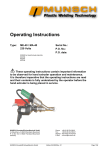
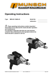
Operating Instructions
Type:
ME-25 / MA-25
230 Volts
Serial No.:
P.O. No.:
P.O. date:
K02951 for Hand Extruder Ident-No.
K02798
K02799
These operating instructions contain important information
to be observed for hand extruder operation and maintenance.
It is therefore imperative that the operating instructions are read
and their contents is fully understood by the operator before the
hand extruder is being placed in service.
MUNSCH Kunststoff-Schweißtechnik GmbH
Im Staudchen • D-56235 Ransbach-Baumbach
P. O. Box 142 • D-56221 Ransbach-Baumbach
Germany
MUNSCH Kunststoff-Schweißtechnik GmbH
Phone:
Fax:
Internet:
E-Mail:
Edition 09.2002/Rev. 01
+49 (0) 26 23-8 98-0
+49 (0) 26 23-8 98-21
http://www.munsch.de
[email protected]
Page 1/32
Hand Extruder ME-25/MA-25
Scope of delivery:
Please check, if the delivery is complete.
The delivery comprises:
1 Hand extruder
1 Handle
1 Welding shoe, shaped
1)
1 Extruder stand
1 Hot-air hood
1 Nozzle
Container engineering design c.w.:
1 Welding shoe for fillet weld a = 7 mm, L = 40 mm
Landfill construction design c.w.:
1 Welding shoe for film weld 25 mm, L = 40 mm
Page 2/32
Edition 09.2002/Rev. 01
MUNSCH Kunststoff-Schweißtechnik GmbH
Table of Contents
1
GENERAL ........................................................................................................................................................5
2
SAFETY ...........................................................................................................................................................5
2.1
2.2
2.3
2.4
2.5
2.6
2.7
3
TRANSPORT AND STORAGE .......................................................................................................................9
3.1
3.2
3.3
4
TRANSPORT ................................................................................................................................................9
STORAGE ....................................................................................................................................................9
RETURN TO MUNSCH ................................................................................................................................9
PRODUCT DESCRIPTION............................................................................................................................10
4.1
4.2
5
IDENTIFICATION OF INFORMATION IN THE OPERATING INSTRUCTIONS...............................................................6
PERSONNEL QUALIFICATION AND TRAINING....................................................................................................6
RISKS RESULTING FROM NON-OBSERVANCE OF THE SAFETY INSTRUCTIONS ....................................................6
SAFE WORKING PRACTICES ..........................................................................................................................6
SAFETY INSTRUCTIONS FOR OPERATOR/USER ...............................................................................................6
SAFETY INSTRUCTIONS FOR MAINTENANCE, INSPECTION AND MOUNTING ........................................................8
UNAUTHORISED MODIFICATIONS AND SPARE PARTS .......................................................................................8
ALLOWABLE SERVICE RANGE ......................................................................................................................10
GENERAL DESCRIPTION .............................................................................................................................10
STARTUP AND SHUTOFF............................................................................................................................11
5.1
GENERAL ..................................................................................................................................................11
5.2
PREPARATION ...........................................................................................................................................11
5.3
STARTING THE HAND EXTRUDER .................................................................................................................12
5.4
WELDING WITH THE HAND EXTRUDER ..........................................................................................................13
5.4.1
Introducing the welding rod..............................................................................................................13
5.4.2
Replacement and ageing of welding rod .........................................................................................13
5.4.3
Welding direction/rate ......................................................................................................................14
5.4.4
Interruption of work ..........................................................................................................................14
5.4.5
Shutoff..............................................................................................................................................14
5.4.6
Transport/storage.............................................................................................................................15
5.5
ADJUST TEMPERATURE CONTROLLER .........................................................................................................15
5.5.1
Adjust temperature controller...........................................................................................................15
6
MAINTENANCE/INSPECTION......................................................................................................................16
6.1
MAINTENANCE/INSPECTION OF HAND EXTRUDER ME-25/MA-25 ..................................................................16
6.2
DISMANTLING ............................................................................................................................................16
6.2.1
ME-25 hand extruder with external air supply .................................................................................16
6.2.2
MA-25 hand extruder with integrated air supply ..............................................................................16
7
MALFUNCTIONS , CAUSES AND REMEDIES............................................................................................27
7.1
7.2
8
TROUBLE-SHOOTING ..................................................................................................................................27
FAULT DIAGNOSIS ......................................................................................................................................27
TECHNICAL DATA........................................................................................................................................29
ME-25 / MA-25
Edition 09.2002/Rev. 01
Seite 3/32
Hand Extruder ME-25/MA-25
Konformitätserklärung des Herstellers
im Sinne der EG-Maschinenrichtlinie 98/37/EG Anhang II B,
Declaration of Conformity by the Manufacturer
as defined by machinery directive 98/37/EEC, Annex II B
MUNSCH Kunststoff-Schweißtechnik GmbH
Im Staudchen
D-56235 Ransbach-Baumbach
hereby declares on its own behalf and responsibility that the hand extruder:
Machine type:
Hand Extruder
Design designation:
ME-25
MA-25
to which this declaration refers conforms to the following standards, codes or regulations:
EU Machinery Directive 98/37/EG
EN 55014-2
EU Low Voltage Directive 73/23/EWG
EN 61000-3-2
EU Directive EMV 89/336/EWG
EN 61000-3-3
EN 55011
EN 55014-1
Conformance of this industrial tool with the above standards is subject to the condition that it is used in
accordance with the contractually agreed service conditions, the responsibility for which shall rest with the user.
Modifications to the machine/unit or the use of the machine/unit for applications other than the intended service
will make this declaration null and void, unless expressly approved in writing by the manufacturer.
Ransbach-Baumbach, August 2002
Page 4/32
Dipl.-Ing. Stefan Munsch
Managing Director
Edition 09.2002/Rev. 01
MUNSCH Kunststoff-Schweißtechnik GmbH
1 General
These operating instructions must always
be available at the place of use of the hand
extruder.
The objective of these operating instructions is to
support operators in familiarizing themselves with the
hand extruder and in using its functions for the
intended service.
Non-compliance with the safety instructions may in
particular involve the following risks:
• failure of important hand extruder functions,
• hazards to persons due to electrical and
mechanical impacts including risk of burns
• hazards to the environment due to vapors of
hazardous substances,
• risk of fire.
2 Safety
The operating instructions provide important
information for the safe, workmanlike and
economical operation of the hand extruder. Their
observance helps avoid danger, minimize repair
costs and downtimes, enhance reliability and extend
the service life of the hand extruder.
Any person performing work with/on the hand
extruder is required to read the operating
instructions. Such work includes
• operation,
• maintenance (maintenance, inspection, repair),
• transport.
The hand extruder shall only be installed, operated
and maintained by trained personnel.
In addition to the operating instructions and the
national and local accident prevention regulations
applicable at the place of use, the acknowledged
technical rules for safe and proper working practices
must be observed.
These operating instructions provide basic
information to be observed for operation and
maintenance. For this reason, it is imperative that
they be read by the specialist personnel/operators
prior to placing the hand extruder in service and that
they are permanently available at the place of use.
Apart from the general safety instructions under
chapter “Safety“, also the special safety instructions
given under the respective sub-sections must be
adhered to.
Failure to observe the safety instructions may
cause hazards to persons and the environment or
damage to the hand extruder.
Moreover, non-observance of the safety instructions
may lead to the forfeiture of any damages.
ME-25 / MA-25
These operating instructions contain important
information to be followed for operation and
maintenance. For this reason, it is imperative that
they be read by the responsible specialist
personnel/operators before mounting and starting-up
of the hand extruder and that they are permanently
available at the place of use.
Operating reliability of the hand extruder
presupposes that the instructions under Chapter 1
“General“ herein are complied with. In no case must
the limit values indicated be violated.
The hand extruders are in conformance with all
applicable standards and meet the prescribed limit
values with regard to EMC (electromagnetic
discharges and interference immunity), provided they
are not defective and have not been modified.
Nevertheless, they emit electromagnetic fields within
the acceptable limits. Electromagnetic fields may
interfere with the operation of vital electronic devices
(e. g. cardiac pacemakers). Users of cardiac
pacemakers should consult their physician before
using the machine.
In addition to the operating instructions and the
national and local accident prevention regulations
applicable at the place of use, the acknowledged
technical rules for safe and proper working practices
are to be observed.
Apart from the safety instructions contained in
this chapter, also the special safety instructions
given under the respective subsections must be
adhered to.
Any working practices posing a safety risk is
prohibited.
Edition 09.2002/Rev. 01
Seite 5/32
Hand Extruder ME-25/MA-25
2.1 Identification of information in the operating
instructions
In these operating instructions, safety instructions
whose non-observance may cause hazards to
persons are identified with
(hazard symbol according to DIN 4844 – W 9),
for general hazards and with
(hazard symbol according to DIN 4844 – W 8).
for electrical hazards.
Safety instructions whose non-observance may
cause damage to the hand extruder and its functions
are marked with
CAUTION .
Instructions directly indicated on the hand extruder
must be strictly followed and kept in a fully readable
condition.
2.2 Personnel qualification and training
The operation, maintenance and inspection
personnel must have the necessary qualification for
the work to be carried out. Functional and technical
responsibilities and supervision of the operating
personnel must be clearly regulated by the Operator.
Where the personnel does not have the necessary
skills and knowledge, they must be trained and
instructed (e.g. DVS basic welder training in
extrusion welding). A detailed instruction into hand
extruder operation will be provided by the
manufacturer/supplier on request. Furthermore, the
Operator has to make sure that the contents of the
operating instructions is fully understood by the
personnel.
Page 6/32
2.3 Risks resulting from non-observance of the
safety instructions
Failure to observe the safety instructions may cause
hazards to person and the environment as well as
damage to the hand extruder.
Moreover, non-compliance with the safety
instructions may lead to the forfeiture of any
damages.
Non-compliance with the safety instructions may in
particular involve the following risks:
• failure of important hand extruder functions,
• hazards to persons due to electrical and
mechanical impacts and risk of burns,
• hazards to the environment due to vapors of
hazardous substances,
• risk of fire.
2.4 Safe working practices
The safety instructions given in these operating
instructions, the applicable national accident
prevention regulations and any existing in-company
work, operating and safety instructions issued by the
Operator are to be followed.
2.5 Safety instructions for operator/user
• Prior to startup, it is to be checked if the mains
voltage and frequency correspond with the data
indicated on the type tag. The allowable
tolerances are ±5 % for voltage and/or ±2 % for
frequency.
• According to VDE°0100 §55, the hand extruder is
to be operated via a residual current-operated
circuit breaker or an isolating transformer.
• CAUTION During hand extruder operation (under
load), a voltage of at least 230 V1) must be
available at the mains connector.
• If an extension cable is used, the minimum
conductor cross section must be observed. Use
extension cables with protective conductors only.
Length
[m]
up to 19
20-50
Minimum cross section
[mm²]
4,0 1)
6,0 1)
1) for 230 V AC
Edition 09.2002/Rev. 01
MUNSCH Kunststoff-Schweißtechnik GmbH
• Extension cables must be certified for the
respective service conditions (e.g. outdoor
service) and identified accordingly.
•
Always handle the connecting cable with care.
Make sure to stand on a firm base when
operating the hand extruder.
-Do not kink the connecting cable.
-Do not place any items on the cable.
-Do not jam or squeeze the connecting cable
nor pull it over sharp edges.
-Protect the connecting cable from moisture.
•
•
Do not touch mains connector or
connecting cable with wet hands. Hold the cable
always at the connector when plugging or
unplugging it.
Connecting cable, welding rod and hose for
external air supply, if applicable, must be freely
movable and must not disturb the operator or
third persons in their work.
•
≥ 4 x rated output of hand extruder
Make sure that the hand extruder does not
come into contact with water, as this may cause a
hazard to persons, damage to the unit or a shortcircuit.
•
CAUTION Never operate the hand extruder
without air supply; risk of equipment damage.
Hold and touch the hand extruder only on
the handles provided for this purpose.
- Do not touch bare metal parts (including hot
air hood) either with or without gloves. These
parts reach temperatures of up to 350°C.
- Attachments may be damaged by the weight of
the hand extruder or may be impaired in their
function.
- Bare metal parts must not come into contact
with other items during the work or breaks
(e.g. cooling).
CAUTION If a power set is used for power
supply, the set must have the following rated
output:
•
The hand extruder must not be used in
explosion hazard areas or flammable
environments.
und bei Pausen (z. B. Abkühlen) nicht mit
Gegenständen in Berührung kommen).
BILD D02-0001
When using external air supply, make sure that
the air supply line is adequately dimensioned.
•
CAUTION The air supplied must be clean, dry
and free from oil and water.
D02-0001
•
Contact of combustible components
with hot bare metal parts poses a fire risk!
Do not use synthetic gloves!
ME-25 / MA-25
Edition 09.2002/Rev. 01
Seite 7/32
Hand Extruder ME-25/MA-25
• Do not direct the hot air jet of the hand extruders
toward living beings or temperature-sensitive
items.
Safety distance: 2 m radius.
BILD D02-0002
2.6 Safety instructions for maintenance,
inspection and mounting
The Operator is responsible for ensuring that all
maintenance, inspection and mounting work is
performed by authorised and qualified personnel
who is thoroughly familiar with the operating
instructions.
360°
• As a rule, the hand extruder must be shut down
and the mains connector unplugged before
carrying out any work on the unit. The shutoff
procedure for the hand extruder must be strictly
followed.
• Electrical hazards are to be ruled out (for details,
see VDE regulations and standards of your local
electric utility, for instance).
)
(6 ft
m
2
•
D02-0002
• Use suitable personal protection for overhead
work (e.g. hard hat, goggles, gloves, protective
clothes) to guard against falling items.
• During work breaks and after completion of the
work, place the hand extruder on the rests
included in the supply.
CAUTION The hot air hood must be re-mounted.
Make sure that the hand extruder is firmly
positioned!
Place hand extruder in a dry location.
After finishing work, cool the hand extruder to
safe-to-touch temperature using the air supply
system.
•
Do not operate, dismantle or carry out
modifications on the hand extruder, if
VDE 0701 (IEC 335) prescribes the
measurement of the protective conductor
resistance, insulation resistance and leakage
current after any maintenance work on or
modifications of electrical equipment.
Furthermore, a visual inspection of the unit and
its connecting cable as well as a voltage and
power measurement and a function test must be
carried out.
• Ensure the safe and environment-friendly
disposal of utilities, auxiliaries and replaced parts.
• Re-mount and/or re-activate all safety and
protection devices immediately on completion of
the work.
2.7 Unauthorised modifications and spare parts
Modifications or changes to the unit are only
permitted after consultation with the manufacturer. In
the interest of safety, only original spare parts and
accessories authorised by the manufacturer should
be used. The use of components other than the
original parts may invalidate the liability for any
resulting damage.
- connecting cable or mains connector are
defective,
- safety devices are damaged,
- foreign matter or liquid has penetrated into
the hand extruder
- the unit does not work properly or there
are unusual changes in the operating mode.
•
Never allow the hand extruder to come into
contact with water, as this may cause a hazard to
persons, damage to the equipment as well as a
short-circuit.
Page 8/32
Edition 09.2002/Rev. 01
MUNSCH Kunststoff-Schweißtechnik GmbH
3 Transport and Storage
3.1 Transport
•
•
Before transport or storage, the hand
extruder must have cooled down to safe-totouch temperature.
The hand extruder may only be held and
touched on the handles provided for this purpose.
Bare metal parts (including the hot air hood) must
not be touched either with or without gloves
before having made sure that they are safe to
touch. These parts reach temperatures of up to
350°C during operation.
3.2 Storage
• Store the hand extruder in a dry and frost-free
place.
• Protect the hand extruder from unauthorised
access.
• Special preservation is not required.
3.3 Return to MUNSCH
Should it become necessary to return the hand
extruder to MUNSCH KunststoffSchweißtechnik GmbH, always use the original
packaging.
BILD D02-0001
D02-0001
• Never transport or store the hand extruder in
such a way that the attachments are exposed to
mechanical loads.
If parts have been removed for transport
purposes, mount and fasten them carefully before
restarting the unit!
MUNSCH's original packaging or the transport
cases offered by MUNSCH are recommended
for transport.
ME-25 / MA-25
Edition 09.2002/Rev. 01
Seite 9/32
Hand Extruder ME-25/MA-25
4 Product Description
4.1 Allowable service range
The allowable service range of the hand extruder is
defined by the data on the type tag and the service
range limits indicated in these operating instructions.
The Powerbox has three LEDs:
- red: undervoltage, defective
- yellow: temporary drive overload
- green: normal operation
CAUTION Operation of the hand extruder outside
the allowable service range stated in these operating
instructions is not allowed without the manufacturer’s
prior approval.
4.2 General Description
Type ME-25 is a hand extruder with external air
supply.
For both types of hand extruder, the following
parameters can be freely selected:
-
Type MA-25 is a hand extruder with integrated air
supply (Autoair).
welding rate,
hot air temperature,
temperature and weld material throughput; the
throughput can be controlled downwards from the
maximum value,
firstly by using 3-mm instead of 4-mm welding
rod, secondly by reducing the speed with the aid
of the rotary button on the Powerbox or the finetuning button of the drive. When reducing the
speed, care must be taken to maintain the
minimum extrudate throughput:
- welding rod ∅ 3 mm, minimum 0,8 kg/h
- welding rod ∅ 4 mm, minimum 1,3 kg/h
CAUTION If the speed is too low, there is a risk of
drive overheating!
Powerbox WX 2PBMU
Powerbox WX 2PBMU is required for the operation
of the hand extruder. It consists of a power pack,
frequency inverter and an EMC filter. The drive
speed and hence, the extrudate output are set at the
power box.
Page 10/32
Driven by a powerful electric motor (1), the welding
rod (2) is fed into the extruder (3) and granulated by
the extruder screw in the process. The screw then
forces the granulate into the extruder nozzle, melting
it to a homogeneous, completely plastified welding
material. As the moIten material exits the extruder
nozzle, it is moulded to the geometry of the weld to
be deposited by a welding shoe (4).
Preheating of the base material to be joined is
achieved by preheating nozzle (5) which is supplied
from an integrated hot air unit (6). Air is either
supplied from an external compressor or an
integrated blower.
Edition 09.2002/Rev. 01
MUNSCH Kunststoff-Schweißtechnik GmbH
Welding material and preheating air temperatures
are controlled separately. The setpoints and actual
values are displayed concurrently.
5.2 Preparation
• Place hand extruder and powerbox on a firm
support and secure it against tilting over as
shown below.
BILD BA.EX003.10-00.REV-01
• Mount hot air hood.
For the drive to be released for starting, the weld
material and preheating air temperatures must be
higher than the respective start-up temperatures.
The temperature-controlled start interlock prevents
drive starting, if there is still unmolten weld material
in the extruder, thus forestalling damage to the unit.
As the output rate is variable, weld thickness and
preheating time can be matched with each other.
5 Startup and Shutoff
5.1 General
In addition to the operating instructions and the
national and local accident prevention regulations
applicable at the place of use, the acknowledged
technical rules for safe and proper working practices
must be observed.
• Position handle
Loosen handle (55) and bring it to ideal working
position by pushing it back and forth. The handles
of MA-25 and ME-25 hand extruders can be
swivelled upwards and downward (see sectional
drawings on pages 17 and 22).
• Only for ME-25 hand extruder with
external air supply:
Connect hand extruder to external air supply;
minimum hose diameter of ½“, for connection to
hand extruder (21.2); minimum air rate 300 l/min
at 0.4 bar.
CAUTION The supply air must be clean, dry and
free from oil and water.
Do not connect external air supply to the MA-25
hand extruder with integrated air supply.
Any working practices posing a safety risk are
prohibited.
Before beginning the startup/shutoff procedure,
the chapter “Safety“ should be carefully read.
Only trained and qualified personnel shall be
assigned to the operation of the hand extruder.
ME-25 / MA-25
Edition 09.2002/Rev. 01
Seite 11/32
Hand Extruder ME-25/MA-25
• Mount welding shoe
- Select the welding shoe required for the
specific weld geometry or machine a
welding shoe blank to the required geometry.
- Observe regulation DVS°2207 Part°4 for
machining welding shoe blanks.
- Mount welding shoe on the hand extruder in
the position required for welding.
Observe welding direction!
Tighten set screw (25).
• The welding shoe including preheating nozzle
can be rotated through 360° by releasing the set
screw (25). After rotating the welding shoe,
tighten set screw (25) to fix the welding shoe
during welding.
Make sure that the preheating nozzle provides
intense and uniform heating (melting) of the base
material over the entire weld width – at minimum hot
air temperature. For bigger weld seams there is a
wider preheating nozzle available as an accessory.
Page 12/32
5.3 Starting the hand extruder
Observe chapter “Safety“.
•
CAUTION The hand extruder must not be
operated without air supply. Failure to observe
this may cause severe damage to the unit.
•
CAUTION Before plugging in the mains
connector, check that the drive is not set to
continuous operation.
•
CAUTION The hot air hood (128) must be
mounted on the heating cartridge (120) of the
hand extruder.
•
CAUTION Start external air supply for hand
extruder ME-25.
•
CAUTION Connect the cable between the
Powerbox and the hand extruder.
•
CAUTION Plug in mains connector.
•
CAUTION With the MA-25 hand extruder with
integrated air supply, the blower must start
automatically.
Edition 09.2002/Rev. 01
MUNSCH Kunststoff-Schweißtechnik GmbH
•
controlled interlock which prevents drive starting
before the melting temperature is reached. Apart
from the temperature-controlled start interlock,
the brushless drive is equipped with a torque
monitor which prevents hand extruder starting as
long as the operating temperature is not attained
or the extrudate has not molten down.
For temperature values, see page 15
“Temperatures for ME-25/MA-25“.
CAUTION Once air exits preheating nozzle (4),
the heating systems (air/material temperature)
may be switched on via switch (124).
BILD-BA.EX003-10-00-REV01
5.4 Welding with the hand extruder
Observe chapter “Safety“ and data sheet.
General
Welding is to be carried out in accordance with the
regulations of the German Association for Welding
Technology (“Deutscher Verband für Schweißtechnik
DVS“).
The material to be welded and the welding rod must
be dry and clean.
• For operation of the temperature controller, see
sub-section 5.5 "Adjust temperature controller".
For temperature values, see page 15
“Temperatures for ME-25/MA-25“.
• The hand extruder reaches its operating
temperature after approx. 15-20 minutes.
• Set the maximum speed on the drive and preset
the speed on the power box.
5.4.1 Introducing the welding rod
•
CAUTION The hand extruder is provided with two
bores for introducing the welding rod. Make sure
to introduce only one welding rod at a time,
either a 3 mm rod or a 4 mm rod. Never
introduce two rods at a time into the rod bore.
BILD-BA.EX016.08-02.REV02
•
The hand extruder may now only be held
and touched on the handles.
BILD D02-0001
D02-0001
•
CAUTION The start switch of the drive unit may
only be operated, when the operating
temperature has been reached. Otherwise the
hand extruder may be damaged by solidified
weld material present in the extruder. The hand
extruder is equipped with a temperature-
ME-25 / MA-25
5.4.2 Replacement and ageing of welding rod
• The hand extruder comes with two nozzles
(Item 2). Please use nozzle, No. 3 for PP welding
rod and nozzle, No. 2 for PE welding rod.
CAUTION Left-hand thread!
• If the welding rod is replaced, make sure that no
old rod is still present in the hand extruder.
• For this purpose, operate the preheated hand
extruder with the new rod, until clean, new
material discharges.
Edition 09.2002/Rev. 01
Seite 13/32
Hand Extruder ME-25/MA-25
• The DVS regulations also recommend this
measure for hand extruders which have been out
of service for prolonged periods while being filled
with welding rod.
•
Ensure safe and environment-friendly
disposal of any wastes generated!
5.4.3 Welding direction/rate
• Under the pressure of the discharging weld
material, the welding shoe (and the hand
extruder) are moved in welding direction.
• See DVS regulations for welding rate.
5.4.5 Shutoff
Observe chapter “Safety“.
• After finishing the welding work, switch off the
drive unit and deposit the hand extruder as
shown (for illustration, see subsection 5.4.4).
Do not leave the hand extruder unattended.
5.4.5.1 Hand extruder with integrated air supply,
Type MA-25
• Switch off heating systems via switch (124).
BILD-BA.EX003.10-00.REV-01
BILD D02-0026
D02-0026
5.4.4 Interruption of work
•
Observe chapter “Safety“.
Do not leave the hand extruder unattended.
Maintain the air supply.
• When interrupting the welding work, switch off the
drive unit and deposit the hand extruder as
shown below.
•
Maintain the air supply after switching off
the hand extruder, until the unit has completely
cooled down!
• Unplug mains connector.
Never use water or another coolant to
accelerate the cooling process!
Page 14/32
Edition 09.2002/Rev. 01
MUNSCH Kunststoff-Schweißtechnik GmbH
5.4.5.2 Hand extruder with external air supply,
Type ME-25
• Switch off heating systems via switch (124).
• Unplug mains connector of hand extruder.
•
Operating panel
BILD-BA.EX007-10-00.REV01
Maintain the air supply after switching off
the hand extruder, until the unit has completely
cooled down!
Never use water or another coolant to
accelerate the cooling process!
5.4.6 Transport/storage
Observe instructions under chapter
“Transport/storage“.
Never use water or another coolant to
accelerate the cooling process!
5.5 Adjust temperature controller
The weld material and air temperatures are adjusted
at the manufacturer's workshops as shown in the
temperature table for the ME-25 and MA-25 hand
extruders.
A
B
C
D
E
F
G
H
I
Temperature display [°C] or [°F]
Actual value display (red)
Display for controller output „OUT“ (heating on)
Setpoint display (green)
Key „Up“ (temperature setpoint increases)
Key „Down“ (temperature setpoint is reduced)
CAUTION controller lock (do not press key)
CAUTION controller lock (do not press key)
lights up if the start-up temperature is reached
Temperatures for ME-25/MA-25
Material
PP
PE
Material
temperature
200 – 240 °C
200 – 240 °C
Air temperature
250 – 300 °C
250 – 300 °C
If other temperatures are required, they can be set
with the aid of the temperature controller.
5.5.1 Adjust temperature controller
Display for start-up temperature (AL)
This display lights up when the start release
temperature is reached. The start release
temperature has been set to a level of 30°C below
the setpoint at the manufacturer's works. The drive
can be started, once the setpoint temperatures for air
and weld material have been reached.
BILD-BA.EX003.10-00.REV01
ME-25 / MA-25
Edition 09.2002/Rev. 01
Seite 15/32
Hand Extruder ME-25/MA-25
6 Maintenance/Inspection
Pull mains connector before carrying out
maintenance and repair work on the unit.
Maintenance and repair work on electrical tools may
only be carried out by qualified electricians.
6.1 Maintenance/Inspection of hand extruder
ME-25/MA-25
• CAUTION After approx. 500 operating hours, the
hand extruder including drive unit must be
thoroughly cleaned and inspected. This work may
only be carried out at the manufacturer’s
workshops.
•
The hand extruder together with the hot air
hood must have cooled down to safe-to-touch
temperature.
CAUTION Cables, switches, plug-in connections
must be inspected by qualified staff every three
months (regulation to VBG4); the inspection
results must be documented.
• Only original spare parts should be used.
Observe the instructions under chapter “Safety“.
Maintenance and repair work should only be carried
out by qualified personnel or by our service staff.
To ensure the proper function of the hand extruder
over its entire service life for its intended service, we
recommend
- to have all maintenance, inspection and mounting
work carried out by authorised and qualified
personnel who are thoroughly familiar with the
operating instructions,
- to always shut down the unit before carrying out
any work on it,
- to mount and activate all safety and protection
devices immediately after completion of the work.
During maintenance and repair work, make sure that
the hand extruder and its individual components are
firmly positioned.
In addition to the operating instructions and the
national and local accident prevention regulations
applicable at the place of use, the acknowledged
technical rules for safe and proper working practices
are to be observed.
Any working practices posing a safety risk are
prohibited.
Activities outside the above scope may only
be performed at the manufacturer‘s workshop.
Page 16/32
6.2 Dismantling
Prior to dismantling the hand extruder, pull the mains
connector.
The hand extruder must be at ambient temperature.
Damaged mains connection cables and/or
interconnecting cables (142) must be replaced.
“Mended“ lines pose a hazard to life and limb. Cable
replacement is to be carried out by qualified
electricians only.
The safety precautions described under chapters
“Safety“ and “Malfunctions, Causes and Remedies“
must be adhered to.
For dismantling and assembly, the associated overall
drawing must be strictly observed. .
6.2.1 ME-25 hand extruder with external air
supply
Overall drawing No. BA.ME-25.DO.09-02.Rev-01
Parts list ME-25 (K02798)
Exploded view of air heater
Parts list of air heater
6.2.2 MA-25 hand extruder with integrated air
supply
Overall drawing No. BA.MA-25.EO.09-02.Rev-01
Parts list MA-25 (K02799)
Exploded view of hot air blower
Parts list of hot air blower
Edition 09.2002/Rev. 01
MUNSCH Kunststoff-Schweißtechnik GmbH
Overall drawing of ME-25 hand extruder with external air supply
ME-25 / MA-25
Edition 09.2002/Rev. 01
Seite 17/32
Hand Extruder ME-25/MA-25
Parts list of ME-25 hand extruder, 230 Volts
K02798
Item-No.:
Qty.
Ident-No.:
Designation:
2
1
K02921
Nozzle
29
2
1
K02968
Nozzle
39
2a
1
K02922
Compression nozzle
MA/E-25
4
1
K02696
Preheating nozzle 20
MA/E-25 u. 25-S
5
1
K02924
Extruder screw
MA/E-25
15
1
K02669
Axial ball bearing
51203
20
1
K02781
Drive WX2Mu
100983
21.2
1
K01249
Screwed hose nozzle
G 3/8"
21.3
1
K00554
Air connection
threaded elbow 3/8"/12
22
2
K00539
Ear clip
d 20
25
1
K02201
Grub screw
M 6 x 12
25.4
2
K02200
Grub screw
M6x6
25.5
1
K02200
Grub screw
M6x6
25.6
2
K02200
Grub screw
M6x6
30
1
K00657
Circlip
I 35 x 1,5
51
2
K00664
Screw connection
PG 9
54
1
K01484
Screwed cable guide
PG 16
55
1
K02941
Handle
M 8 MA/E-25 u. 25-S
61
1
K02187
Temperature control
E5GN-Q1TC 100-240 VAC
65
1
K02836
Diode for ME-60,40,25,-H
230V / 2000 W
66
1
K00674
Air hose
14 x 18
76
1
K02279
Holding angle for casing
MA/E-60,40,25,G50 230/400
81
1
K02741
Hot air guide
20° ME-25
82
1
K02187
Temperature control
E5GN-Q1TC 100-240 VAC
86
1
K02703
Extruder body
MA/E-25 u. 25-S
112
1
K02585
Holder
DO ME-25
115
1
K02933
Touch guard
MA/E-25 u. 25-S
117
1
K02698
Distance ring
17/3 MA/E-25 u. 25-S
120
1
K02603
Heating cartridge
21x31x 50 MA/E-25
121.6
1
K02055
Spring washer
A5
122
4
K02052
Socket head cap screw
M 5 x 16
122.5
1
K02952
Socket head cap screw
M 5 x 25
123
1
K02670
Ball bearing
6003-2RS1
124
1
K02753
Switch
MA/E-60
125
4
K00684
Slotted cheese head screw
M4x6
125.2
4
K00684
Slotted cheese head screw
M4x6
125.3
2
K02202
Slotted cheese head screw
M5x6
Page 18/32
Edition 09.2002/Rev. 01
MUNSCH Kunststoff-Schweißtechnik GmbH
Parts list of ME-25 hand extruder, 230 Volts
K02798
Item-No.:
Qty.
Ident-No.:
Designation:
126.1
1
K02073
Solid state relais
G3NE-210T 12 VDC
127
1
K00625
Key
5 x 5 x 14
129
1
K02278
Casing cover
S/R, MA/E-60,40,25,G50 230/400
130
1
K02280
Casing - lower section
m.Drahtf.MA/E-60,40,25 230/400
137
1
K02931
Feather shim
25 x 35 x 1
140
1
K02834
Main electric connection board
MA/E-60,40,25
141
4
K02653
Toothed washer M 5
d 1 = 5,3 A2
142
1
K02775
Connecting cable (powerbox - drive)
WX2PBMu-WX2Mu
145
1
K02936
Guide bar
MA/E-25 u. 25-S
146
1
K02937
Clamping ring
MA/E-25 u. 25-S
147
1
K02938
Distance piece
MA/E-25 u. 25-S
148
1
K02963
Support ring
MA/E-25 u. 25-S
149
1
K02965
Joint ring
MA/E-25 u. 25-S
o
1
K02205
Dust cap
321-212
ME-25 / MA-25
Edition 09.2002/Rev. 01
Seite 19/32
Hand Extruder ME-25/MA-25
Exploded view of air heater for ME-25 hand extruder
Drawing in preparation
Page 20/32
Edition 09.2002/Rev. 01
MUNSCH Kunststoff-Schweißtechnik GmbH
Parts list of air heater for ME-25 hand extruder
Spare parts list in preparation
ME-25 / MA-25
Edition 09.2002/Rev. 01
Seite 21/32
Hand Extruder ME-25/MA-25
Overall drawing of MA-25 hand extruder with integrated air supply
Page 22/32
Edition 09.2002/Rev. 01
MUNSCH Kunststoff-Schweißtechnik GmbH
Parts list of MA-25 hand extruder, 230 Volts
K02799
Item-No.:
Qty.
Ident-No.:
Designation::
2
1
K02921
Nozzle
29
2
1
K02968
Nozzle
39
2a
1
K02922
Compression nozzle
MA/E-25
4
1
K02696
Preheating nozzle 20
MA/E-25 u. 25-S
5
1
K02924
Extruder screw
MA/E-25
15
1
K02669
Axial ball bearing
51203
20
1
K02781
Drive WX2Mu
100983
21
1
K02203
Air connection
angle 1/4"
21.1
1
K00725
Air connection
angle 1/4"
25
1
K02201
Grub screw
M 6 x 12
25.4
2
K02200
Grub screw
M6x6
25.5
1
K02200
Grub screw
M6x6
25.6
2
K02200
Grub screw
M6x6
30
1
K00657
Circlip
I 35 x 1,5
51
2
K00664
Screw connection
PG 9
54
1
K01484
Screwed cable guide
PG 16
55
1
K02941
Handle
M 8 MA/E-25 u. 25-S
61
1
K02187
Temperature control
E5GN-Q1TC 100-240 VAC
66
1
K00713
Air hose
9x3
76
1
K02279
Holding angle for casing
MA/E-60,40,25,G50 230/400
82
1
K02187
Temperature control
E5GN-Q1TC 100-240 VAC
86
1
K02703
Extruder body
MA/E-25 u. 25-S
87
1
K02740
Integrated air-unit mounting
23° MA-25
88
1
K02206
Hot-air blower
Electron o.E.-230 Volt, 2200 W
111
1
K02584
Holder
EO MA-25
115
1
K02933
Touch guard
MA/E-25 u. 25-S
117
1
K02698
Distance ring
17/3 MA/E-25 u. 25-S
120
1
K02603
Heating cartridge
21x31x 50 MA/E-25
121.6
1
K02055
Spring washer
A5
122
4
K02052
Socket head cap screw
M 5 x 16
122.5
1
K02952
Socket head cap screw
M 5 x 25
123
1
K02670
Ball bearing
6003-2RS1
124
1
K02753
Switch
MA/E-60
125
4
K00684
Slotted cheese head screw
M4x6
125.2
4
K00684
Slotted cheese head screw
M4x6
125.3
2
K02202
Slotted cheese head screw
M5x6
ME-25 / MA-25
Edition 09.2002/Rev. 01
Seite 23/32
Hand Extruder ME-25/MA-25
Parts list of MA-25 hand extruder, 230 Volts
K02799
Item-No.:
Qty.
Ident-No.:
Designation::
126.1
1
K02073
Solid state relais
G3NE-210T 12 VDC
127
1
K00625
Key
5 x 5 x 14
129
1
K02278
Casing cover
S/R, MA/E-60,40,25,G50 230/400
130
1
K02280
Casing - lower section
m.Drahtf.MA/E-60,40,25 230/400
137
1
K02931
Feather shim
25 x 35 x 1
140
1
K02834
Main electric connection board
MA/E-60,40,25
141
4
K02653
Toothed washer M 5
d 1 = 5,3 A2
142
1
K02775
Connecting cable (powerbox - drive)
WX2PBMu-WX2Mu
145
1
K02936
Guide bar
MA/E-25 u. 25-S
146
1
K02937
Clamping ring
MA/E-25 u. 25-S
147
1
K02938
Distance piece
MA/E-25 u. 25-S
148
1
K02963
Support ring
MA/E-25 u. 25-S
149
1
K02965
Joint ring
MA/E-25 u. 25-S
o
1
K02205
Dust cap
321-212
Page 24/32
Edition 09.2002/Rev. 01
MUNSCH Kunststoff-Schweißtechnik GmbH
Exploded view of hot air blower for MA-25-B/D hand extruder
ME-25 / MA-25
Edition 09.2002/Rev. 01
Seite 25/32
Hand Extruder ME-25/MA-25
Parts list of hot air blower for MA-25-B/D hand extruder
Item
Qty.
Art. No.
Designation
1
2
3
4
5
6
7
8
9
10
11
12
13
14
15
16
17
18
19
20
21
22
23
24
25
26
27
28
29
30
1
1
1
1
6
1
1
2
2
2
1
1
1
1
3
1
1
1
1
1
4
1
1
1
1
1
1
1
1
1
107.753
104.271
111.824
100.032
100.299
101.237
111.743
101.243
101.250
101.249
106.394
101.251
101.252
104.064
100.284
107.591
107.762
107.592
100.287
107.763
101.269
101.270
101.776
101.760
105.385
100.288
8.7
107.765
100.528
104.272
Corrugated conduit, black
Hose coupling DN 12
Handle
LEISTER company logo
Oval head screw M4 x 10
O-ring ø 75.92 x ø 1.78
Clamp strap
Self-tapping oval head screw
Carbon 5 x 6 x 16
Carbon brush guide
Motor 54/25 230V
Steel sleeve
Rubber ring without cam
Turbine housing, lower part
Self-tapping oval head screw
Turbine
Distributor, complete
Turbine
Hexagon nut M5
Turbine housing, upper part
Oval head self-tapping screw M3.5 x 8
Gasket 70x48x4mm
Heating element, type 32
Mica tube
Pipe adapter with protective tube
Thermocouple
Relay
Flexible insulating tube ø 7 x 0.7 x 90
Warning sign "hot surface"
Counter nut PA PG9, black
Page 26/32
Edition 09.2002/Rev. 01
450mm
PG 9 straight
75 x 22
M3.5x8
complete
M4 x 14
with square nuts
complete
230V/2200W
white
MUNSCH Kunststoff-Schweißtechnik GmbH
7 Malfunctions , Causes and Remedies
7.1 Trouble-shooting
The following table lists potential malfunctions of the
hand extruder together with likely causes and their
remedies (fault diagnosis chart).
Malfunction
Drive motor does not start
Drive motor switches off
No welding rod feed
No weld material conveyed out of the welding shoe
Weld material feed rate decreases during operation
No compressed air
Failure of integrated air supply
No hot air
Hot air temperature below setpoint
Weld material temperature below setpoint
Extruder remains cold
Temperature above the preset range
Temperature display on the controller: 5.err
Temperature display on the controller: e.111
Temperature display on the controller: ⊏⊏⊏⊏
Fault No.
5, 8, 9, 10, 11, 12, 14, 15, 16, 17, 18, 19, 21, 23, 25
5, 8, 9, 10, 11, 12, 14, 15, 16, 17, 18, 19, 21, 23, 25
1, 16, 17, 20, 26
1, 16, 26
1, 14, 16
13
22, 5
2, 3, 4, 5, 18, 22, 24
2, 3, 4, 8, 10, 18, 22, 14
2, 3, 9, 11, 14, 24
2, 3, 12, 22, 24
2, 3, 18, 19
27
28
29
30
Temperature display on the controller: ⊐⊐⊐⊐
Variations from setpoint temperature
3, 13, 19
7.2 Fault diagnosis
Fault
Possible causes
No.
Welding rod diameter smaller or too small
1
Temperatur sensor defective
2
Temperatur controller defective
3
Air throughput too high
4
Cable connections defective
5
External air supply not connected3)
6
External air supply out of function3)
7
8
If malfunctions occur which are not covered here or
which cannot be traced back to the cause indicated,
please contact MUNSCH KunststoffSchweißtechnik GmbH.
Hot air temperature below the start release
temperature.
Remedies
If necessary, use a larger welding rod diameter.
1)
1)
Reduce air supply to the specified rate.3)
Check cable connections.1)
Connect external air supply.
Switch on external air supply.
Check the external air supply system for
malfunctions using the separate manual, or have it
checked.
Allow the hand extruder to heat up.
Air flow too high Æ lower air flow.
1) Consult MUNSCH Kunststoff-Schweißtechnik GmbH
2) Only MA-25
3) Only ME-25
ME-25 / MA-25
Edition 09.2002/Rev. 01
Seite 27/32
Hand Extruder ME-25/MA-25
Fault
No.
9
10
11
12
13
Possible causes
Remedies
Welding deposit temperature below the start
release temperature
Preheating time for hot air too short
Preheating time for weld material too short
Heating cartridge defective
Air supply not constant
Allow the hand extruder to heat up.
Allow the hand extruder to heat up
Allow the hand extruder to heat up.
1)
-
With external air supply:
Check air supply3)
-
With integrated air supply:
-
1)
14
Rated voltage > permissible voltage
Check mains voltage
Incorrect rated voltage
Rated voltage < permissible voltage
Check mains voltage
1)
15
Extension cable heats up
Unroll the cable reel
Check cable cross section (see chapter “Safety“)
Clean extruder.
-
16
Extruder nozzle blocked with foreign matter
Extruder nozzle – left-hand thread
17
18
19
20
Defect in the drive unit
Defect in the electronic control
Controller programming incorrect
Welding rod feed
1)
1)
1)
Remove welding rod
Observe the instructions under chapter
“Maintenance“!
Observe the instructions for extruder operation!
21
22
23
24
25
26
27
28
Powerbox fault
Hot air unit defective
No mains voltage
Heating switched off
Yellow LED on Powerbox lights up
Rod feed bores mixed up
Input error
„s.err“ at controller
Memory error
„e111“ at controller
1)
1)
Check voltage supply.
Operate switch 124
Allow hand extruder to heat up
Do not introduce ∅ 3-mm-rod into 4-mm-feed-bore!
Check inputs for incorrect wiring, cable discontinuity,
input type and short-circuits.
First switch voltage off and then on. If the display
does not change, the unit needs to be repaired. If the
display is correct, an external interference affecting
the controller may be the cause. Check for external
interferences.
1) Consult MUNSCH Kunststoff-Schweißtechnik GmbH
2) Only MA-25
3) Only ME-25
Page 28/32
Edition 09.2002/Rev. 01
MUNSCH Kunststoff-Schweißtechnik GmbH
Fault
No.
29
30
Possible causes
Actual value out of range
Actual value out of range
Remedies
Although this is no fault, the message is displayed, if
the out-of-range actual value is smaller than the
display range.
⊏⊏⊏⊏
- Smaller than “-1999“
Although this is no fault, the message is displayed, if
the out-of-range actual value is greater than the
display range.
- Greater than “9999“
⊐⊐⊐⊐
1) Consult MUNSCH Kunststoff-Schweißtechnik GmbH
2) Only MA-25
3) Only ME-25
8 Technical Data
Type designation
Welding materials
Welding rates, approx.
Welding rod
Service range
Weight
Drive
Extruder heating
Air heater
Air supply
Air consumption
Weld material
temperature control
Air temperature control
Cold start protection
ME-25 / MA-25
ME-25
PP, PE
∅ 3 mm: 1.3 kg/h PP; 1.3 kg/h PE
∅ 4 mm: 2.4 kg/h PP; 2.5 kg/h PE
Welding rod ∅ 3 and 4 mm
Wall thicknesses 4-15 mm and film
welds
5 kg
230 V AC, with speed control, external
powerbox
400 W
2000 W
External air
at least 300 l/min at 0.4 bar
Temperature controller with actual value
and set point display
Temperature controller with actual value
and set point display
Temperature-controlled start interlock
as a function of weld material and
preheating air temperatures
Edition 09.2002/Rev. 01
MA-25
PP, PE
∅ 3 mm: 1.3 kg/h PP; 1.3 kg/h PE
∅ 4 mm: 2.4 kg/h PP; 2.5 kg/h PE
Welding rod ∅ 3 and 4 mm
Wall thicknesses 4-15 mm and film
welds
6 kg
230 V AC, with speed control, external
powerbox
400 W
2200 W
Integrated air supply
at least 300 l/min
Temperature controller with actual value
and set point display
Temperature controller with actual value
and set point display
Temperature-controlled start interlock
as a function of weld material and
preheating air temperatures
Seite 29/32
Hand Extruder ME-25/MA-25
Warranty Certificate
..............................................................................................................
..............................................................................................................
..............................................................................................................
Name and address of Purchaser
Type of unit:
Hand extruder
Type designation:
ME-25 / MA-25
Serial number:
Purchase order date:
Your Warranty
MUNSCH Kunststoff-Schweißtechnik GmbH hereby
warrants the unit to be free from defects in material and
workmanship from the date of its first acquisition. Should
deficiencies resulting from defects in materials or
workmanship be identified during the warranty period, the
dealers will, in accordance with the following conditions,
repair the unit or - at their discretion – replace the unit or
the defective components without charging labour or
material costs.
..............................................................................................................
Stamp and signature of dealer
Page 30/32
Edition 09.2002/Rev. 01
MUNSCH Kunststoff-Schweißtechnik GmbH
Warranty
1 The manufacturer warrants freedom from defects
in materials and workmanship and state-of-theart performance of the purchased article for a
period of six months from the date of delivery.
2
3
The Purchaser shall check the article delivered
for completeness and freedom from defects
immediately after receipt.
The Purchaser is entitled to the making good of
defects and any resulting damage to other parts
of the purchased article (remedial work).
The procedure for claims under this warranty
shall be as follows:
3.1 The Purchaser may assert claims under this
warranty either with his dealer or with a company
authorized by the manufacturer to provide
services for the purchased article. The Purchaser
shall give written notice of defects to the
respective company immediately after such
defects have been identified or have such
defects registered by the respective company.
3.2 Defects shall be promptly remedied in
accordance with the technical requirements by
either replacement or repair of the defective
parts, the cost of the remedial work being for the
account of the Manufacturer. Replaced parts
shall become the property of the Manufacturer.
If, as a result of the remedial work, additional
maintenance measures are prescribed by the
Manufacturer, the resulting costs including the
costs of materials and lubricants shall be for the
Manufacturer's account.
3.3 For replacement parts installed within the scope
of the remedial work, a new 6-months warranty
period shall begin from the date of replacement.
3.4 For the warranty to become effective, this
warranty certificate must be produced before
each repair.
4
If the defect cannot be remedied or if the
Purchaser cannot be reasonably expected to
accept further attempts at making good the
defect, the Purchaser may demand annulment
(cancellation of the purchase contract) or a price
reduction (reduction of compensation) in lieu of
remedial work. In such a case, the Purchaser
shall no be entitled to any replacement.
5
Manufacturer's warranty obligations shall not be
affected by a change in ownership of the
purchased article.
ME-25 / MA-25
6
Expressly excluded from this warranty is
damage incurred through
6.1 Purchaser's failure to report a defect pursuant to
subsection 3a) or to provide an opportunity to
remedy the defect immediately upon request
6.2 improper handling or overload operation of the
purchased article or
6.3 prior repair, maintenance or servicing of the
purchased article by a company not authorized
by the manufacturer, if the Purchaser can be
reasonably expected to have known that such
company was not authorized;
6.4 the installation of parts into the purchased article
without having obtained the Manufacturer's prior
approval for such parts or the modification of the
purchased article in a way not approved by the
Manufacturer or
6.5 Purchaser's failure to observe the instructions
given in the user’s manual accompanying the
purchased article (e.g. operation, maintenance
and care) or
6.6 the Purchaser having removed the serial number
or made it illegible.
7
Natural wear and tear shall be expressly
excluded from the warranty.
8
Accidents, force majeure or other circumstances
beyond the control of the Manufacturer, in
particular damage caused by lightning,
overvoltage, water, fire etc. shall be excluded
from the warranty.
9
All rights under this warranty shall become null
and void on expiry of the warranty term pursuant
to Section 1. For claims asserted within the
warranty term but not settled by its expiry, the
warranty shall remain effective until the
respective defect is remedied. The period of
limitation shall be suspended for such claim.
Edition 09.2002/Rev. 01
Seite 31/32
Hand Extruder ME-25/MA-25
MUNSCH Kunststoff-Schweißtechnik GmbH
Im Staudchen • D-56235 Ransbach-Baumbach
P. O. Box 142 • D-56221 Ransbach-Baumbach
Germany
Phone: +49 (0) 26 23-8 98-0
Fax:
+49 (0) 26 23-8 98-21
Internet: http://www.munsch.de
E-mail: [email protected]
Page 32/32
Edition 09.2002/Rev. 01
MUNSCH Kunststoff-Schweißtechnik GmbH