1
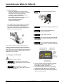
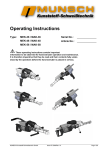
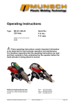
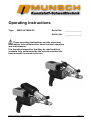
Operating Instructions
Type:
MEK-25 / MAK-25
Serial No.:
______________
Article No.:
______________
These operating instructions contain important
information to be observed for hand extruder operation
and maintenance.
It is therefore imperative that they be read and their
contents fully understood by the operators before the
hand extruder is placed in service.
MUNSCH Kunststoff-Schweißtechnik GmbH
Issue 12.2009/Rev. 02
Page 1/20
Hand Extruder MEK-25 / MAK-25
Scope of delivery:
Please check that the delivery is complete.
The delivery comprises:
1 hand extruder
1 handle
1) Container engineering design: fillet weld a = 7mm, 40mm long
1) Landfill construction design: sheeting/film weld 25mm, 40mm
long
1 welding shoe, machined 1)
1 extruder stand
1 hot air hood
Contents
1
GENERAL ......................................................................................................................................................................4
2
SAFETY ..........................................................................................................................................................................4
2.1
2.2
2.3
2.4
2.5
2.6
2.7
3
TRANSPORT AND STORAGE ...................................................................................................................................8
3.1
3.2
3.3
4
TRANSPORT ...............................................................................................................................................................8
STORAGE ...................................................................................................................................................................8
RETURN TO MUNSCH .................................................................................................................................................8
PRODUCT DESCRIPTION .........................................................................................................................................8
4.1
4.2
5
IDENTIFICATION OF INFORMATION IN THE OPERATING INSTRUCTIONS .......................................................................5
PERSONNEL QUALIFICATION AND TRAINING ..............................................................................................................5
RISKS RESULTING FROM NON-OBSERVANCE OF THE SAFETY INSTRUCTIONS ..............................................................5
SAFE WORKING PRACTICES ........................................................................................................................................5
SAFETY INSTRUCTIONS FOR OPERATOR / OPERATING PERSONNEL .............................................................................5
SAFETY INSTRUCTIONS FOR MAINTENANCE, INSPECTION AND MOUNTING .................................................................7
UNAUTHORIZED MODIFICATIONS AND SPARE PARTS ..................................................................................................7
APPLICATION RANGE .................................................................................................................................................8
GENERAL ...................................................................................................................................................................8
STARTUP AND SHUTOFF..........................................................................................................................................9
5.1
GENERAL ...................................................................................................................................................................9
5.2
PREPARATION ............................................................................................................................................................9
5.3
STARTING THE HAND EXTRUDER .............................................................................................................................10
5.4
WELDING WITH THE HAND EXTRUDER .....................................................................................................................11
5.4.1
Introducing the welding rod............................................................................................................................11
5.4.2
Replacement and aging of welding rod...........................................................................................................11
5.4.3
Welding direction / rate ..................................................................................................................................11
5.4.4
Interruption of work........................................................................................................................................11
5.4.5
Shutoff ............................................................................................................................................................12
5.4.6
Transport/Storage............................................................................................................................................12
5.5
SET TEMPERATURES ON TEMPERATURE CONTROLLER .............................................................................................12
5.5.1
Set temperatures..............................................................................................................................................12
6
MAINTENANCE/INSPECTION ...............................................................................................................................14
6.1
MAINTENANCE/INSPECTION OF MEK/MAK HAND EXTRUDER ................................................................................14
6.2
DISMANTLING..........................................................................................................................................................14
6.2.1
Overview of spare parts/attachments ..............................................................................................................14
7
MALFUNCTIONS, CAUSES AND REMEDIES......................................................................................................16
7.1
7.2
8
TROUBLE-SHOOTING................................................................................................................................................16
FAULT DIAGNOSIS ....................................................................................................................................................16
TECHNICAL DATA ...................................................................................................................................................18
Page 2/20
Issue 12.2009/Rev. 02
MUNSCH Kunststoff-Schweißtechnik GmbH
EG-Konformitätserklärung des Herstellers
nach der EG-Maschinenrichtlinie 2006/42/EG Anhang II, Nr. 1 A
EC-Declaration of Conformity by the Manufacturer
as defined by machinery directive 2006/42/EC, Annex II, No. 1 A
MUNSCH Kunststoff-Schweißtechnik GmbH
Im Staudchen
D-56235 Ransbach-Baumbach
Germany
Mr. Johann Dausenau,
Kunststoffschweißtechnik GmbH,
is authorised to compile the technical documentation.
We hereby declare that the hand extruders
Machine type:
Hand extruder
Hand extruder
Type designation:
MEK-25
MAK-25
are in accordance with all relevant provisions of the EC Machinery Directive.
The following harmonised standards (or parts of these standards) were applied:
DIN EN ISO 12100-1: 2004
DIN EN 13732-1: 2008
DIN EN ISO 12100-2: 2004
In addition, the hand extruders are in accordance with the following EC-directives, standards, codes and
regulations:
EU Low-Voltage Directive 73/23/EC
EU EMC Directive 89/336/EC
EN 60204-1 (VDE 0113 Part 1): 2007
DIN EN 55014-1: 2007
EN 61029-1 (VDE 0740 Part 500): 2003
DIN EN 55014-2: 2009
VDE 0701 Part 1: 2008
VDE 0702 Part 1: 2003
This industrial tool complies with the aforesaid standards insofar as it is used at the contractually agreed
conditions. The operator is responsible for this.
In the event of any modifications to the machine/unit or use not as intended, this declaration becomes invalid
unless the manufacturer’s prior written approval has expressly been given.
Ransbach-Baumbach, 29.12.2009
MEK-25 / MAK-25
Dipl.-Ing. Stefan Munsch
Managing Director
Issue 12.2009/Rev. 02
Page 3/20
Hand Extruder MEK-25 / MAK-25
1 General
These operating instructions must always
be available at the place of use of the hand
extruder.
The objective of these operating instructions is to
support operators in familiarizing themselves with the
hand extruder and in using its functions for the
intended service.
These operating instructions provide important
information for the safe, workmanlike and
economical operation of the hand extruder. Their
observance helps avoid danger, minimize repair
costs and downtimes, enhance reliability, and extend
the service life of the hand extruder.
These operating instructions must be observed by all
persons working with/on the hand extruder. Such
work includes, for instance:
• operation,
• maintenance, inspection and repair
• transport.
The hand extruder may only be mounted, operated
and maintained by trained personnel.
In addition to the operating instructions and the
national and local accident prevention regulations
applicable at the place of use, the acknowledged
technical rules for safe and proper working practices
must be observed.
These operating instructions provide basic
information to be observed for operation and
maintenance. For this reason, it is imperative that
they be read by the specialist personnel/Operator
prior to placing the hand extruder in service and that
they always be available at the place of use.
Apart from the general safety instructions under
section “Safety“, also the special safety instructions
given under the respective sub-sections must be
adhered to.
Non-observance of the safety instructions
may cause hazards to persons and the environment
or damage to the hand extruder.
Moreover, failure to observe the safety instructions
may lead to the forfeiture of any damages.
Page 4/20
Non-observance of the safety instructions may in
particular involve the following risks:
• failure of important hand extruder functions,
• hazards to persons due to electrical and
mechanical impacts including risk of burns,
• hazards to the environment due to vapour-phase
hazardous substances,
• risk of fire.
2 Safety
These operating instructions provide basic
information to be observed for operation and
maintenance. For this reason, it is imperative that
they be read by the specialist personnel/Operator
prior to placing the hand extruder in service and that
they always be available at the place of use.
Safe operation of the hand extruder presupposes
that the instructions under section 1 – General – of
these operating instructions are complied with. In no
case must the limit values indicated be violated.
Intact and unaltered hand extruders conform to the
applicable codes and standards and meet all
regulatory limit values regarding EMC
(electromagnetic discharges and interference
immunity). For the country-specific limit values to be
observed, the Operator should consult the local
electric utility. Nevertheless, the hand extruders emit
electromagnetic fields within the acceptable limits.
Electromagnetic fields may interfere with the
operation of vital electronic devices (e.g. cardiac
pacemakers). Persons wearing a cardiac pacemaker
should therefore consult their physician before using
the machine.
In addition to the operating instructions and the
national and local accident prevention regulations
applicable at the place of use, the acknowledged
technical rules for safe and proper working practices
must be observed.
Apart from the general safety instructions under
section “Safety“, also the special safety instructions
given under the respective sub-sections must be
adhered to.
Any working practices posing a safety risk are
prohibited.
Issue 12.2009/Rev. 02
MUNSCH Kunststoff-Schweißtechnik GmbH
2.1 Identification of information in the operating
instructions
In these operating instructions, safety instructions
whose non-observance may cause hazards to
persons are identified with
2.3 Risks resulting from non-observance of the
safety instructions
Non-observance of the safety instructions may cause
hazards to persons and the environment or damage
to the hand extruder. Moreover, failure to observe
the safety instructions may lead to the forfeiture of
any damages.
Non-observance of the safety instructions may in
particular involve the following risks:
• failure of important hand extruder functions,
• hazards to persons due to electrical and
mechanical impacts including risk of burns,
• hazards to the environment due to vapour-phase
hazardous substances,
• risk of fire.
Hazard symbol according to DIN 4844 – W 9
for general hazards and with
Hazard symbol according to DIN 4844 – W 8
for electrical hazards.
Safety instructions whose non-observance may
cause damage to the hand extruder and its functions
are marked with
CAUTION
Instructions directly indicated on the hand extruder
must be strictly followed and kept in a fully legible
state.
2.2 Personnel qualification and training
The operating, maintenance and inspection
personnel must possess appropriate qualification for
the work to be performed. Functional and technical
responsibilities and supervision of the operating
personnel must be clearly regulated by the Operator.
Where the personnel do not have the necessary
skills and knowledge they must be trained and
instructed (e.g. a DVS basic welder training in
extrusion welding). A detailed instruction into hand
extruder operation will be provided by the
Manufacturer/Supplier on request. Furthermore, the
Operator has to make sure that the contents of the
operating instructions is fully understood by the
operating personnel.
MEK-25 / MAK-25
2.4 Safe working practices
The safety instructions given in these operating
instructions, the applicable national accident
prevention regulations and any existing in-company
work instructions, operating and safety procedures
issued by the Operator must be followed.
2.5 Safety instructions for Operator / operating
personnel
• Before placing the hand extruder in service,
check the mains voltage and frequency against
the data indicated on the type tag. The allowable
tolerances are ± 5 % for voltage and/or ±2 % for
frequency.
• According to VDE 0100 §55, the hand extruder
must be operated via a residual current-operated
circuit breaker or an isolating transformer.
• CAUTION During hand extruder operation (under
1)
load), a voltage of not less than 230 V must be
available at the connector of the hand extruder.
• When using an extension cable, make sure to
observe the minimum conductor cross-section.
Use extension cables with protective conductor
only.
Length
[m]
up to 19
20-50
Minimum cross-section
[mm²]
1)
4.0
1)
6.0
1) for 230 V AC
Issue 12.2009/Rev. 02
Page 5/20
Hand Extruder MEK-25 / MAK-25
• Extension cables must be certified for the specific
service conditions (e.g. outdoor service) and
identified accordingly.
•
Always handle the connecting cable with care.
•
•
Do not kink the connecting cable.
Do not place any objects on the cable.
Do not jam or squeeze the connecting cable,
nor pull it over sharp edges.
Protect the connecting cable from moisture.
Do not touch the mains connector or
connecting cable with wet hands. Hold the cable
always at the connector when plugging or
unplugging it.
Make sure that the hand extruder is firmly
positioned during the extrusion welding job.
The connecting cable, welding rod and hose for
external air supply, if applicable, must be freely
movable and must not obstruct the operator or
third parties in their work.
•
CAUTION Power generator sets used for power
supply must be designed for the following rated
output:
Never allow the hand extruder to come into
contact with water: Hazard to persons and
equipment, short-circuit risk.
•
CAUTION Never operate the hand extruder
without air supply; risk of hand extruder
damage.
Hold and touch the hand extruder only on
the handles provided for this purpose.
- Do not touch bare metal parts (including hot
air hood) either with or without gloves. These
parts reach temperatures of up to 350 °C.
- Attachments may be damaged or impaired
in their function if subjected to the full weight
of the hand extruder.
- Bare metal parts must not come into contact
with other items during the work or work
breaks (e.g. cooling).
≥ 4 x rated output of hand extruder
•
The hand extruder must not be used in
explosion hazard areas or flammable
atmospheres.
When using an external air source, make sure
that the air supply line is adequately
dimensioned.
•
CAUTION The supply air must be clean, dry and
free from oil and water.
D02-0001
•
Contact of combustible components
with hot bare metal parts poses a risk of fire!
Do not use synthetic gloves!
Page 6/20
Issue 12.2009/Rev. 02
MUNSCH Kunststoff-Schweißtechnik GmbH
• Do not direct the hot air jet of the hand extruder
towards living beings or temperature-sensitive
items.
Safety distance: 2 m radius
BILD D02-0002
360°
• As a rule, the hand extruder must be shut off and
the connector unplugged before proceeding to
any work on the unit. The shutoff procedure for
the hand extruder described in the operating
instructions must be strictly observed.
• Electrical hazards must be ruled out (for details,
see VDE guidelines and the standards of your
local electric utility, for instance).
)
(6 ft
m
2
D02-0002
• Use suitable personal protection equipment for
overhead work (e.g. hard hat, safety goggles,
gloves, protective clothes …) to guard against
falling items.
• During work breaks and after completion of the
welding job, place the hand extruder on the rests
supplied for this purpose.
CAUTION The hot air hood must be remounted.
Make sure that the hand extruder is firmly
positioned!
Deposit the hand extruder in a dry location.
After completion of the welding job, cool the hand
extruder to safe-to-touch temperature, using the
air supply system.
•
Do not operate, dismantle or carry out any
modifications on the hand extruder, if
- the connecting cable or the mains connector
is defective,
- safety devices are damaged,
- foreign matter or liquid has penetrated into the
hand extruder,
- the unit does not work properly or there are
unusual changes in its operating behaviour.
•
Never allow the hand extruder to come into
contact with water: Hazard to persons and
equipment, short-circuit risk.
MEK-25 / MAK-25
2.6 Safety instructions for maintenance,
inspection and mounting
The Operator is responsible for ensuring that
maintenance, inspection and mounting activities are
performed by authorized and qualified personnel
who are thoroughly familiar with the operating
instructions.
•
VDE 0701 (IEC 335) prescribes the
measurement of the protective conductor
resistance, insulation resistance and leakage
current after each repair or modification to
electrical equipment. Furthermore, a visual
inspection of the unit and its connecting cable as
well as voltage and current measurements and a
function test must be carried out.
• Ensure the safe and environmentally compatible
disposal of media, auxiliary materials and
replaced parts!
• Remount and reactivate all safety and protective
devices immediately on completion of the
maintenance, inspection or repair work.
2.7 Unauthorized modifications and spare parts
Modifications or changes to the unit are only allowed
after consultation with the Manufacturer. In the
interest of safety, only original spare parts and
accessories authorized by the Manufacturer should
be used. The use of components other than the
original spare parts may invalidate the
Manufacturer’s liability for any resulting damage.
Issue 12.2009/Rev. 02
Page 7/20
Hand Extruder MEK-25 / MAK-25
CAUTION Operation of the hand extruder outside
the service limits stated in these operating
instructions is subject to the Manufacturer’s prior
approval.
3 Transport and Storage
3.1 Transport
•
•
Before transport and storage, make
sure that the hand extruder has cooled down
to safe-to-touch temperature.
4.2 General
Type MEK is a hand extruder with external air
supply.
Hold and touch the hand extruder only on
the handles provided for this purpose.
Do not touch bare metal parts (including the hot
air hood) – whether with or without gloves before having made sure that they are safe to
touch. These parts reach temperatures of up to
350 °C during operation.
Type MAK is a hand extruder with integrated air
supply (Autoair).
D02-0001
• Always transport or store the hand extruder in
such a way as to preclude any mechanical loads
on the attachments.
If parts have been removed for transport
purposes, mount and fasten them carefully before
restarting the hand extruder!
Transport of the hand extruder in MUNSCH’s
original shipping case is recommended.
3.2 Storage
• Store the hand extruder in a dry and frost-free
place.
• Protect the hand extruder from unauthorized
access.
• Special preservation is not required.
Powerbox WX 2PBMU
Powerbox WX 2PBMU is required for the operation
of the hand extruder. It consists of a power pack, a
frequency inverter and an EMC filter. The drive
speed, and hence, the melt throughput are set on the
Powerbox.
The Powerbox has three LEDs:
- red:
undervoltage, defective
- yellow: temporary drive overload
- green: normal operation
3.3 Return to Munsch
Should it become necessary to return the hand
extruder to MUNSCH Kunststoff-Schweißtechnik
GmbH, always use the original shipping case.
4 Product Description
4.1 Application range
The application range of the hand extruder is defined
by the data on the type tag and the service limits
indicated in these operating instructions.
Page 8/20
Issue 12.2009/Rev. 02
MUNSCH Kunststoff-Schweißtechnik GmbH
For both types of hand extruder, the following
parameters can be freely selected:
-
welding rate,
hot air temperature,
melt temperature and throughput; the melt
throughput can be controlled downward from the
maximum value,
firstly by using 3 mm instead of 4 mm welding
rod and, secondly, by reducing the speed using
the rotary button on the Powerbox or the finetuning button of the drive.
5.1 General
In addition to the operating instructions and the
national and local accident prevention regulations
applicable at the place of use, the acknowledged
technical rules for safe and proper working practices
must be observed.
Any working practices posing a safety risk are
prohibited.
Before starting / shutting off the hand extruder, make
sure to carefully read the instructions under section
“Safety”.
CAUTION Too low a speed will cause a risk of drive
overheating!
Only trained and qualified personnel may be
assigned to the operation of the hand extruder.
Driven by a powerful electric motor (1), the welding rod (2)
is fed into the extruder (3) and granulated by the extruder
screw in the process. The screw forces the granulate into
the extruder nozzle, melting it into a homogeneous,
completely plastified mass. As the molten material exits
the extruder nozzle, it is moulded by a welding shoe (4) to
the geometry of the weld seam to be deposited.
5.2 Preparation
• Place hand extruder and Powerbox on a firm
support and secure them against toppling over.
Preheating of the base material to be joined is
accomplished by a preheating nozzle (5) which is supplied
from an integrated hot air unit (6). Air is supplied either
from an external compressor or an on-board blower.
Melt and preheat temperatures are controlled
separately. The setpoint and momentary values are
displayed concurrently.
The melt temperature must have reached the preset
start interlock temperature for the startup timer to
be activated. After the startup timer has timed out,
the start interlock will be released and the extruder
can be started.
The temperature-controlled start interlock prevents
the drive from starting if there is still unmolten
material in the extruder, thus precluding damage to
the unit.
The output rate is variable so that the preheat
temperature can be matched to the weld thickness.
5 Startup and Shutoff
MEK-25 / MAK-25
• Mount hot air hood
• Position handle
Loosen handle (55) and move it to the ideal
working position by pushing it back and forth. The
handles of these extruder models can also be
swivelled upward and downward.
• Only for MEK hand extruder with external air
supply:
Connect the hand extruder to the external air
source using the hose coupling LW 13 / NM 7.2
provided for this purpose (quick connectdisconnect); set air rate to 300 l/min at 0.4 bar. A
suitable controller with flow metering function is
recommended for setting the air rate.
CAUTION The supply air must be clean, dry and
free from oil and water.
Never connect an external air source to a
MAK hand extruder.
Issue 12.2009/Rev. 02
Page 9/20
Hand Extruder MEK-25 / MAK-25
• Mount welding shoe
- Select the welding shoe required for the
specific weld geometry or machine a welding
shoe blank to the required geometry.
- Observe DVS 2207 Guideline, Part 4 for
machining welding shoe blanks.
- Mount welding shoe to the hand extruder in
the position required for welding.
Observe welding direction!
Tighten set screw (25).
• The welding shoe including preheat nozzle can
be rotated through 360° by releasing the set
screw (25). After rotating the welding shoe,
tighten set screw (25) to fix the welding shoe in
place for the welding operation.
•
CAUTION The hot air hood must be in place.
•
CAUTION Start external air supply for MEK hand
extruder.
•
CAUTION Connect the cable between the
Powerbox and the hand extruder.
•
CAUTION Plug in mains connector.
•
CAUTION In the case of the MAK hand extruder
with integrated air supply, the blower must start
automatically.
•
CAUTION Once air exits the preheat nozzle (4),
the heating systems for the air/melt temperatures
may be activated.
Care must be taken to ensure that the preheat
nozzle provides intensive and uniform preheating
(melting) of the base material over the entire joint
width at as low a hot air temperature as possible. For
larger weld seam widths, a wider preheat nozzle is
available as an accessory.
5.3 Starting the hand extruder
Observe section “Safety“.
•
•
CAUTION Never operate the hand extruder
without air supply. Otherwise the unit may suffer
severe damage.
CAUTION Before plugging in the mains
connector, check that the drive unit is not set to
continuous operation.
Page 10/20
• For the operation of the temperature controller,
see section 5.5 “Set temperatures“. For
temperature settings, see page 12.
• The hand extruder will reach its operating
temperature after about 10 to 15 minutes.
• Set the drive speed to maximum and select the
speed on the Powerbox.
Issue 12.2009/Rev. 02
MUNSCH Kunststoff-Schweißtechnik GmbH
•
Hold and touch the hand extruder only on
the handles provided for this purpose.
5.4.2 Replacement and aging of welding rod
• If the welding rod is to be replaced, make sure
that any remaining rod in the hand extruder is
completely removed.
• For this purpose, operate the preheated hand
extruder with the new welding rod until clean new
material discharges.
• The DVS guideline also recommends this
procedure for hand extruders which have been
out of service for prolonged periods while still
being filled with welding rod.
•
D02-0001
•
CAUTION The melt temperature must have
reached the preset start interlock temperature
for the startup timer to be activated. After the
startup timer has timed out, the start interlock will
be released and the extruder can be started.
In addition to the start temperature interlock, the
brushless drive is equipped with a torque control
which prevents the extruder from starting as long
as the operating temperature is not reached
and/or melting of the extrudate is incomplete.
Ensure safe and environmentally
compatible disposal of any waste generated!
5.4.3 Welding direction / rate
• The pressure of the discharging extrudate causes
the welding shoe (and hence, the hand extruder)
to move in welding direction.
• See DVS Guidelines for the welding rate.
5.4 Welding with the hand extruder
Observe section “Safety” and the data sheet.
D02-0026
General
Welding is to be carried out in accordance with the
guidelines of the German Association for Welding
Technology (Deutscher Verband für Schweißtechnik
DVS).
The parts to be joined and the welding rod must be
clean and dry.
•
Observe section “Safety“.
Do not leave the hand extruder unattended.
Make sure to maintain the air supply.
• When interrupting the welding job, switch off the
drive unit and deposit the hand extruder as
shown in the illustration below.
5.4.1 Introducing the welding rod
•
5.4.4 Interruption of work
CAUTION The hand extruder is provided with a
bore for introducing the welding rod.
MEK-25 / MAK-25
Issue 12.2009/Rev. 02
Page 11/20
Hand Extruder MEK-25 / MAK-25
5.4.5 Shutoff
Observe section “Safety”.
• After completion of the welding job, switch off
the drive unit and deposit the hand extruder as
shown in the illustration (see preceding section).
Do not leave the hand extruder unattended.
5.4.5.1 Hand extruder with integrated air supply,
type MAK
• Press “return“ button once to switch off the
heating circuits.
5.4.6 Transport/Storage
Make sure to observe the instructions under section
“Transport/Storage“.
5.5 Set temperatures on temperature controller
The default settings for the melt and air temperatures
of the MEK and MAK hand extruders are shown in
the following temperature chart.
(The values have been determined with the aid of
reference materials.)
Temperature chart for MEK/MAK
Material
PP
PE
PVDF
Melt temperature
200 – 240 °C
200 – 240 °C
240 – 260 °C
Air temperature
250 – 300 °C
250 – 300 °C
280 – 350° C
If other temperatures are needed the corresponding
settings can be made on the temperature controller.
5.5.1 Set temperatures
•
Maintain the air supply of the hand
extruder until the unit has completely cooled
down!
• Pull mains connector.
5.4.5.2 Hand extruder with external air supply,
type MEK
• Press “return“ button once to switch off the
heating circuits.
• Pull mains connector.
•
Maintain the air supply of the hand
extruder until the unit has completely cooled
down!
Never use water or another coolant to
accelerate the cooling process!
Page 12/20
Issue 12.2009/Rev. 02
MUNSCH Kunststoff-Schweißtechnik GmbH
MEK-25 / MAK-25
Issue 12.2009/Rev. 02
Page 13/20
Hand Extruder MEK-25 / MAK-25
6 Maintenance/Inspection
Pull mains connector before carrying out any
maintenance and repair work on the hand extruder.
Maintenance and repair work on electrical tools may
only be carried out by qualified electricians.
The hand extruder together with the hot air
hood must have cooled down to safe-to-touch
temperature.
Observe the instructions under section “Safety“.
6.2 Dismantling
Prior to dismantling the hand extruder, pull the mains
connector.
The hand extruder must be at ambient temperature.
Damaged power cables and/or connecting cables
(between the Powerbox and the hand extruder) must
be completely replaced. “Mended” cables pose a
hazard to life and limb. Cable replacement is to be
carried out by qualified electricians only.
The safety precautions described under sections
“Safety“ and “Malfunctions, Causes and Remedies“
must be strictly adhered to.
Maintenance and repair work may only be carried
out by qualified personnel or by our service staff.
To ensure the proper function of the hand extruder
over its entire service life for its intended service, we
recommend:
- to have all maintenance, inspection and mounting
work carried out by authorized and qualified
personnel who are familiar with the operating
instructions,
- to always shut off the unit before carrying out any
work on it,
- to remount and reactivate all safety and
protective devices immediately after completion
of the maintenance/repair work.
6.2.1 Overview of spare parts/attachments
When ordering spare parts, always indicate the
serial number of the extruder.
Make sure to use original spare parts only.
For spare parts supply, contact MUNSCH KunststoffSchweißtechnik GmbH.
---------------------------------------------------------------------Extruder screw bearing:
K02669 = Axial bearing (replace)
K04361 = Ball bearing (replace)
K04362 = Circlip (replace, if necessary)
K02965 = Seal ring (replace)
K02698 = Spacer ring (replace, if necessary)
During maintenance and repair work, make sure that
the hand extruder and its individual components are
firmly positioned.
In addition to the operating instructions and the
national and local accident prevention regulations
applicable at the place of use, the acknowledged
technical rules for safe and proper working practices
must be observed.
----------------------------------------------------------------------
Any working practices posing a safety risk are
prohibited.
Activities other than those described in this
section may only be performed at the Manufacturer’s
workshops!
6.1 Maintenance/inspection of MEK/MAK hand
extruder
• CAUTION After approx. 500 operating hours, the
hand extruder including drive unit must be
thoroughly cleaned and inspected. This work may
only be carried out at the manufacturer’s
workshops.
• CAUTION Cables, switches, plug-in connections
must be inspected by qualified staff every three
months (requirement according to VBG4); the
inspection results must be documented..
Page 14/20
Issue 12.2009/Rev. 02
MUNSCH Kunststoff-Schweißtechnik GmbH
----------------------------------------------------------------------------------------------------------------------------------------------------
----------------------------------------------------------------------------------------------------------------------------------------------------
MEK-25 / MAK-25
Issue 12.2009/Rev. 02
Page 15/20
Hand Extruder MEK-25 / MAK-25
7 Malfunctions, Causes and Remedies
7.1 Trouble-shooting
The following table lists potential operating upsets of
the hand extruder, possible causes and their
remedies (fault diagnosis chart).
Should malfunctions occur which are not covered
here or which cannot be traced back to the cause
stated, please contact MUNSCH KunststoffSchweißtechnik GmbH.
Malfunction
Fault No.
Drive motor does not start
Drive motor switches off
No welding rod feed
No extrudate conveyed out of welding shoe
Extrudate output decreases during operation
No air supply
Integrated air supply without function
No hot air
Hot air temperature below setpoint temperature
Melt temperature below setpoint temperature
Extruder does not heat up
Temperature above preset range
Controller fault signal: E
Controller fault signal: OEAIR
Controller signal: OFF
Control fluctuates
5, 8, 9, 10, 11, 12, 14, 15, 16, 17, 18, 19, 21, 23, 25
5, 8, 9, 10, 11, 12, 14, 15, 16, 17, 18, 19, 21, 23, 25
1, 16, 17, 20
1, 16
1, 14, 16
6, 7, 13
5, 22
2, 3, 4, 5, 6, 18, 22
2, 3, 4, 8, 10, 18, 22, 14
2, 3, 9, 11, 14
2, 3, 12, 22
2, 3, 18, 19
2
2, 13, 22
9, 10, 11, 12
3, 13,19,12
7.2 Fault diagnosis
Fault
No.
1
2
3
4
5
6
7
8
Possible causes
Remedies
Smaller or too small a welding rod diameter
Temperature sensor defective
Temperature controller defective
Air rate too high
Cable connections defective
3)
External air supply not connected
3)
External air supply without function
Use larger welding rod diameter, if necessary
Reduce air rate to specified level
1)
Check cable connections
Connect external air supply
Switch on external air supply
Hot air temperature below start interlock
temperature
Check the external air supply system for
malfunctions using the separate manual, or have it
checked.
Allow hand extruder to heat up
3)
Air rate too high → reduce air rate
1)
1)
3)
1) Consult MUNSCH Kunststoff-Schweißtechnik GmbH
2) Only for MAK
3) Only for MEK
Page 16/20
Issue 12.2009/Rev. 02
MUNSCH Kunststoff-Schweißtechnik GmbH
Fault
No.
9
10
11
12
13
Possible causes
Remedies
Melt temperature below start interlock
temperature
Preheat time for hot air too short
Preheat time for melt too short
Heating cartridge defective
Air supply not constant
Allow hand extruder to heat up
Allow hand extruder to heat up
Allow hand extruder to heat up
1)
-
External air supply:
3)
Check air supply unit
-
Integrated air supply:
-
1)
14
Rated voltage > permissible voltage
Check mains voltage
Wrong rated voltage
Rated voltage < permissible voltage
Check mains voltage
1)
15
Extension cable heats up
Unroll cable reel
Check cable cross-section (see also section
“Safety“)
Clean extruder.
-
16
Extruder nozzle plugged with foreign matter
Extruder nozzle – left-hand thread
17
18
19
20
Drive unit defective
Electronic control defective
Controller programming error
Welding rod feed
1)
1)
1)
Remove welding rod
Observe instructions in section “Maintenance“!
Observe instructions for operation!
21
22
23
25
Powerbox malfunction
Hot air unit defective
No mains voltage
Yellow LED on Powerbox lights up
1)
1)
Check voltage supply
Allow hand extruder to heat up
1) Consult MUNSCH Kunststoff-Schweißtechnik GmbH
2) Only for MAK
3) Only for MEK
MEK-25 / MAK-25
Issue 12.2009/Rev. 02
Page 17/20
Hand Extruder MEK-25 / MAK-25
8 Technical Data
Type designation
Welding materials
Welding rate, approx.
Welding rod
Application range
Weight
Drive
Extruder heating system
Air preheater
Air supply
Air rate
Control of melt
temperature
Control of air
temperature
Cold start protection
Page 18/20
MEK
PP, PE, PVDF
25 = ∅ 3 mm: 1.4 kg/h PP/PE
25 = ∅ 4 mm: 2.5 kg/h PP/PE
Welding rod ∅ 3 and 4 mm
25 = Wall thicknesses 4-15 mm and
film/sheeting welds
25 = 5 kg
230 V AC with speed control, external
Powerbox
25 = 400 W
2100 W
External air source
300 l/min at 0.4 bar
Temperature controller with concurrent
momentary value and setpoint display
Temperature controller with concurrent
momentary value and setpoint display
Start temperature interlock and startup
timer for melt and preheat air
Issue 12.2009/Rev. 02
MAK
PP, PE, PVDF
25 = ∅ 3 mm: 1.4 kg/h PP/PE
25 = ∅ 4 mm: 2.5 kg/h PP/PE
Welding rod ∅ 3 and 4 mm
25 = Wall thicknesses 4-15 mm and
film/sheeting welds
25 = 6 kg
230 V AC with speed control, external
Powerbox
25 = 400 W
2300 W
Integrated air supply
-----------Temperature controller with concurrent
momentary value and setpoint display
Temperature controller with concurrent
momentary value and setpoint display
Start temperature interlock and startup
timer for melt and preheat air
MUNSCH Kunststoff-Schweißtechnik GmbH
Warranty Certificate
..............................................................................................................
..............................................................................................................
..............................................................................................................
Name and address of Purchaser
Type of unit:
Hand extruder
Type designation:
Serial no.:
P.O. date:
Your warranty
MUNSCH Kunststoff-Schweißtechnik GmbH hereby
warrants the unit to be free from defects in materials and
workmanship from the date of its first acquisition. Should
deficiencies resulting from defects in materials or
workmanship be identified during the warranty period, the
dealers will, in accordance with the following terms and
conditions, repair the unit or, at their discretion, replace
either the complete unit or the defective components
without charging labour or material costs.
..............................................................................................................
Dealer’s stamp and signature
MEK-25 / MAK-25
Issue 12.2009/Rev. 02
Page 19/20
Hand Extruder MEK-25 / MAK-25
Warranty
1 The Manufacturer warrants freedom from defects
in materials and workmanship and state-of-theart performance of the purchased article for a
period of six (6) months from the date of delivery.
2 The Purchaser shall check the article delivered
for completeness and freedom from defects
immediately after receipt.
3 The Purchaser shall be entitled to the making
good of defects and any resulting damage to
other parts of the purchased article (remedial
work).
The procedure for claims under this warranty
shall be as follows:
3.1 The Purchaser may assert claims under this
warranty either with his dealer or with a company
authorized by the Manufacturer to provide
services for the purchased article. The Purchaser
shall give written notice of defects to the
respective company promptly after such defects
have been identified or shall have such defects
registered by the respective company.
3.2 Defects shall be promptly remedied in
accordance with the technical requirements by
either replacement or repair of the defective
parts, the cost of the remedial work being for the
account of the Manufacturer. Replaced parts
shall become the property of the Manufacturer.
If, as a result of the remedial work, additional
maintenance measures are prescribed by the
Manufacturer, the resulting costs including the
costs of materials and lubricants shall be for the
Manufacturer’s account.
3.3 For replacement parts installed within the scope
of the remedial work, a warranty will be provided
under the purchase contract, the warranty period
for such parts ending on expiry of the warranty
period of the object purchased.
3.4 For the warranty to become effective, this
warranty certificate must be produced for each
repair.
4 If the defect cannot be remedied or if the
Purchaser cannot be reasonably expected to
accept any further attempts at making good the
defect, the Purchaser may demand annulment
(cancellation of the contract) or a price reduction
(reduction of compensation) in lieu of remedial
work. In such a case, the Purchaser shall not be
entitled to any replacement.
5 Manufacturer’s warranty obligations shall not be
affected by a change in ownership of the
purchased article.
6
6.1
6.2
6.3
6.4
6.5
6.6
7
8
9
Any damage incurred through the following acts
or omissions of Purchaser shall be expressly
excluded from this warranty:
Purchaser’s failure to report a defect pursuant to
subsection 3.1 or to promptly provide an
opportunity to remedy the defect following
Manufacturer’s request, or
improper handling or overload operation of the
purchased article, or
prior repair, maintenance and servicing of the
purchased article by a company not authorized
by the Manufacturer, if the Purchaser can be
reasonable expected to have known that such
company was not authorized, or
the installation of parts into the purchased article
without having obtained Manufacturer’s prior
approval for such parts or the modification of the
purchased article in a way not approved by the
Manufacturer, or
Purchaser’s failure to observe the instructions
given in the user’s manual accompanying the
purchased article (e.g. operation, maintenance
and care), or
Purchaser having removed the serial number or
made it illegible.
Natural wear and tear shall be expressly
excluded from this warranty.
Accidents, force majeure or other circumstances
beyond the control of the Manufacturer, in
particular damage caused by lightning,
overvoltage, water, fire, etc. shall be excluded
from this warranty.
All rights under this warranty shall become null
and void on expiry of the warranty term pursuant
to Section 1. For claims asserted within the
warranty term but no settled by its expiry, the
warranty shall remain effective until the
respective defect has been remedied. The period
of limitation shall be suspended for such claim.
MUNSCH Kunststoff-Schweißtechnik GmbH
Im Staudchen • D-56235 Ransbach-Baumbach
P.O. Box 142 • D-56221 Ransbach-Baumbach
Germany
Phone: +49 (0) 26 23-8 98-80
Telefax: +49 (0) 26 23-8 98-85
Internet: http://www.munsch.de
Email: [email protected]
Page 20/20
Issue 12.2009/Rev. 02
MUNSCH Kunststoff-Schweißtechnik GmbH