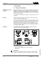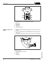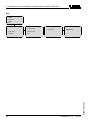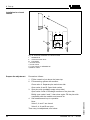
1
Operating Instructions
VEGADIF 65
4 … 20 mA
Document ID:
36236
p
Differential pressure
Contents
Contents
1
About this document
1.1
1.2
1.3
2
.
.
.
.
.
.
.
.
.
.
.
.
.
.
.
.
.
.
.
.
.
.
.
.
.
.
.
.
.
.
.
.
.
.
.
.
.
.
.
.
..
..
..
..
..
..
..
..
..
..
5
5
5
5
6
6
6
6
6
6
.
.
.
.
.
.
.
.
.
.
.
.
.
.
.
.
.
.
.
.
.
.
.
.
.
.
.
.
.
.
.
.
.
.
.
.
.
.
.
.
.
.
.
.
.
.
.
.
..
..
..
..
7
8
12
12
General instructions . . . . . . . . . . . .
Special application conditions . . . . .
Flow measurement . . . . . . . . . . . . .
Level measurement . . . . . . . . . . . .
Density and interface measurement .
Differential pressure measurement. .
Wall or tube mounting. . . . . . . . . . .
External housing. . . . . . . . . . . . . . .
Mounting control. . . . . . . . . . . . . . .
.
.
.
.
.
.
.
.
.
.
.
.
.
.
.
.
.
.
.
.
.
.
.
.
.
.
.
.
.
.
.
.
.
.
.
.
.
.
.
.
.
.
.
.
.
.
.
.
.
.
.
.
.
.
.
.
.
.
.
.
.
.
.
.
.
.
.
.
.
.
.
.
.
.
.
.
.
.
.
.
.
.
.
.
.
.
.
.
.
.
.
.
.
.
.
.
.
.
.
..
..
..
..
..
..
..
..
..
14
15
16
18
23
25
27
27
28
.
.
.
.
.
.
.
.
.
.
.
.
.
.
.
.
.
.
.
.
.
.
.
.
.
.
.
.
.
.
.
.
.
.
.
.
.
.
.
.
.
.
.
.
.
.
.
.
.
.
.
.
.
.
.
.
.
.
.
.
.
.
.
.
.
.
.
.
.
.
.
.
.
.
.
.
.
.
.
.
.
.
.
.
.
.
.
.
..
..
..
..
..
..
..
..
29
30
33
34
35
36
36
37
Configuration . . . . . . . . . . . . . . .
Principle of operation . . . . . . . . .
Operation. . . . . . . . . . . . . . . . . .
Packaging, transport and storage
.
.
.
.
Prepare the connection . . . . . . . . . .
Connection procedure. . . . . . . . . . .
Single chamber housing . . . . . . . . .
Double chamber housing . . . . . . . .
Double chamber housing Ex d . . . .
Version IP 66/IP 68, 1 bar . . . . . . . .
External housing with version IP 68 .
Switch on phase. . . . . . . . . . . . . . .
Short description . . . . . . . . . . . . . . . . . . . . . . . . . . .
Insert indicating and adjustment module. . . . . . . . . . .
Adjustment system . . . . . . . . . . . . . . . . . . . . . . . . . .
39
39
41
VEGADIF 65 • 4 … 20 mA
36236-EN-090604
Adjustment with the indicating and adjustment module
PLICSCOM
6.1
6.2
6.3
2
.
.
.
.
.
.
.
.
.
.
Connect to power supply
5.1
5.2
5.3
5.4
5.5
5.6
5.7
5.8
6
.
.
.
.
.
.
.
.
.
.
Mounting
4.1
4.2
4.3
4.4
4.5
4.6
4.7
4.8
4.9
5
Authorised personnel . . . . . . . . . . . . . . . .
Appropriate use . . . . . . . . . . . . . . . . . . . .
Warning about misuse . . . . . . . . . . . . . . .
General safety instructions . . . . . . . . . . . .
Safety label on the instrument . . . . . . . . . .
CE conformity . . . . . . . . . . . . . . . . . . . . .
Fulfillment of NAMUR recommendations . .
Safety instructions for Ex areas . . . . . . . . .
Safety instructions for oxygen applications .
Environmental instructions. . . . . . . . . . . . .
Product description
3.1
3.2
3.3
3.4
4
4
4
4
For your safety
2.1
2.2
2.3
2.4
2.5
2.6
2.7
2.8
2.9
2.10
3
Function. . . . . . . . . . . . . . . . . . . . . . . . . . . . . . . . . .
Target group . . . . . . . . . . . . . . . . . . . . . . . . . . . . . .
Symbolism used. . . . . . . . . . . . . . . . . . . . . . . . . . . .
Contents
6.4
6.5
6.6
7
Connect the PC via VEGACONNECT . . . . . . . . . . . .
Parameter adjustment with PACTware . . . . . . . . . . . .
Saving the parameter adjustment data . . . . . . . . . . . .
56
56
57
Set up
.
.
.
.
.
.
.
.
.
.
.
.
.
.
.
.
.
.
.
.
.
.
.
.
.
.
.
.
.
.
.
.
.
.
.
.
.
.
.
.
.
.
.
.
.
.
.
.
.
.
.
.
.
.
.
..
..
..
..
..
58
58
60
64
64
.
.
.
.
.
.
.
.
.
.
.
.
.
.
.
.
.
.
.
.
.
.
.
.
.
.
.
.
.
.
.
.
.
.
.
.
.
.
.
.
.
.
.
.
.
.
.
.
.
.
.
.
.
.
.
..
..
..
..
..
67
67
68
68
69
10.1 Dismounting steps . . . . . . . . . . . . . . . . . . . . . . . . . .
10.2 Disposal . . . . . . . . . . . . . . . . . . . . . . . . . . . . . . . . .
70
70
8.1
8.2
8.3
8.4
8.5
9
42
51
55
Operating with PACTware and other adjustment programs
7.1
7.2
7.3
8
Set parameters. . . . . . . . . . . . . . . . . . . . . . . . . . . . .
Menu schematic . . . . . . . . . . . . . . . . . . . . . . . . . . . .
Saving the parameter adjustment data . . . . . . . . . . . .
Select the mode . . . . . . . . . . . . . . .
Flow measurement . . . . . . . . . . . . .
Level measurement . . . . . . . . . . . .
Density and interface measurement .
Differential pressure measurement. .
Maintenance and fault rectification
9.1
9.2
9.3
9.4
9.5
Maintain. . . . . . . . . . . . . .
Remove interferences . . . .
Exchanging the electronics
Software update . . . . . . . .
Instrument repair . . . . . . .
......
......
module
......
......
.
.
.
.
.
10 Dismounting
11 Supplement
11.1 Technical data . . . . . . . . . . . . . . . . . . . . . . . . . . . . .
71
Supplementary documentation
Information:
Supplementary documents appropriate to the ordered version come
with the delivery. You can find them listed in chapter "Product
description".
Instructions manuals for accessories and replacement parts
36236-EN-090604
Tip:
To ensure reliable setup and operation of your instrument, we offer
accessories and replacement parts. The corresponding instructions
manuals are:
l
l
l
VEGADIF 65 • 4 … 20 mA
27720 - External indication VEGADIS 61
34296 - Protective cover
36132 - Electronics module DF60 for VEGADIF 65
3
1 About this document
1 About this document
1.1 Function
This operating instructions manual provides all the information you
need for mounting, connection and setup as well as important
instructions for maintenance and fault rectification. Please read this
information before putting the instrument into operation and keep this
manual accessible in the immediate vicinity of the device.
1.2 Target group
This operating instructions manual is directed to trained qualified
personnel. The contents of this manual should be made available to
these personnel and put into practice by them.
1.3 Symbolism used
Information, tip, note
This symbol indicates helpful additional information.
Caution: If this warning is ignored, faults or malfunctions can
result.
Warning: If this warning is ignored, injury to persons and/or serious
damage to the instrument can result.
Danger: If this warning is ignored, serious injury to persons and/or
destruction of the instrument can result.
Ex applications
This symbol indicates special instructions for Ex applications.
l
à
1
List
The dot set in front indicates a list with no implied sequence.
Action
This arrow indicates a single action.
Sequence
Numbers set in front indicate successive steps in a procedure.
36236-EN-090604
4
VEGADIF 65 • 4 … 20 mA
2 For your safety
2 For your safety
2.1 Authorised personnel
All operations described in this operating instructions manual must be
carried out only by trained specialist personnel authorised by the plant
operator.
During work on and with the device the required personal protective
equipment must always be worn.
2.2 Appropriate use
VEGADIF 65 is a differential pressure transmitter for measurement of
flow, level, differential pressure, density and interface.
You can find detailed information on the application range in chapter
"Product description".
Operational reliability is ensured only if the instrument is properly used
according to the specifications in the operating instructions manual as
well as possible supplementary instructions.
For safety and warranty reasons, any invasive work on the device
beyond that described in the operating instructions manual may be
carried out only by personnel authorised by the manufacturer. Arbitrary
conversions or modifications are explicitly forbidden.
2.3 Warning about misuse
Inappropriate or incorrect use of the instrument can give rise to
application-specific hazards, e.g. vessel overfill or damage to system
components through incorrect mounting or adjustment.
2.4 General safety instructions
This is a high-tech instrument requiring the strict observance of
standard regulations and guidelines. The user must take note of the
safety instructions in this operating instructions manual, the countryspecific installation standards as well as all prevailing safety
regulations and accident prevention rules.
The instrument must only be operated in a technically flawless and
reliable condition. The operator is responsible for trouble-free
operation of the instrument.
36236-EN-090604
During the entire duration of use, the user is obliged to determine the
compliance of the required occupational safety measures with the
current valid rules and regulations and also take note of new
regulations.
VEGADIF 65 • 4 … 20 mA
5
2 For your safety
2.5 Safety label on the instrument
The safety approval markings and safety tips on the device must be
observed.
2.6 CE conformity
This device fulfills the legal requirements of the applicable EC
guidelines. By attaching the CE mark, VEGA provides a confirmation
of successful testing. You can find the CE conformity declaration in the
download area of www.vega.com.
2.7 Fulfillment of NAMUR recommendations
With respect to compatibility, the NAMUR recommendation NE 53 is
fulfilled. This applies also to the corresponding indicating and
adjustment components. VEGA instruments are generally upward and
downward compatible.
l
Indicating and adjustment module for sensor software
The parameter adjustment of the basic sensor functions is independent of the software version. The range of available functions depends
on the respective software version of the individual components.
2.8 Safety instructions for Ex areas
Please note the Ex-specific safety information for installation and
operation in Ex areas. These safety instructions are part of the
operating instructions manual and come with the Ex-approved
instruments.
2.9 Safety instructions for oxygen applications
For instruments in oxygen applications the special instructions in
chapters "Storage and transport", "Mounting" as well as "Technical
data" under "Process conditions"must be noted. Furthermore the valid
national regulations, implementation instructions and memorandums
of the BG (professional assoc.) must be noted.
2.10 Environmental instructions
Protection of the environment is one of our most important duties. That
is why we have introduced an environment management system with
the goal of continuously improving company environmental protection.
The environment management system is certified according to DIN
EN ISO 14001.
l
l
6
Chapter "Packaging, transport and storage"
Chapter "Disposal"
VEGADIF 65 • 4 … 20 mA
36236-EN-090604
Please help us fulfil this obligation by observing the environmental
instructions in this manual:
3 Product description
3 Product description
3.1 Configuration
Scope of delivery
The scope of delivery encompasses:
l
l
l
l
Components
VEGADIF 65 differential pressure transmitter
Depending on the version ventilation valves and/or closing screws
Optional accessory
Documentation
- this operating instructions manual
- Operating instructions manual 27835 "Indicating and adjustment module PLICSCOM" (optional)
- Supplementary instructions manual 31708 "Heating for indicating and adjustment module" (optional)
- Operating instructions 36133 "Isolating diaphragm CSB"
(optional)
- Operating instructions 36134 "Isolating diaphragm CSS"
(optional)
- Supplementary instructions manual "Plug connector for continuously measuring sensors" (optional)
- Ex-specific "Safety instructions" (with Ex-versions)
- Certificate "Oil and grease-free for oxygen applications" (with
respective versions)
- if necessary, further certificates
The following illustration shows the components of VEGADIF 65:
1
2
3
+ –
Fig. 1: VEGADIF 65 in basic version
36236-EN-090604
1
2
3
Housing cover, optionally with integrated indicating and adjustment module
Housing with electronics
Process components with measuring cell
The components are available in different versions.
VEGADIF 65 • 4 … 20 mA
7
3 Product description
Type label
The type label contains the most important data for identification and
use of the instrument:
l
l
l
l
l
l
l
Sensor type
Article number instrument
Ex approval
Technical data: Measuring range, process pressure, process
temperature, signal output, voltage supply, protection, protection
class
Order number, serial number instrument
Hardware and software version
Article numbers, documentation
The serial number allows you to access the delivery data of the
instrument via www.vega.com, "VEGA Tools" and "serial number
search". In addition to the type label outside, you can also find the
serial number on the inside of the instrument.
3.2 Principle of operation
Application area
VEGADIF 65 is a differential pressure transmitter for measurement of
flow, level, differential pressure, density and interface. Measured
products are gases, vapours and liquids.
Flow measurement
+
Q ~ ∆p
p1
+
–
p2
Q
Q ~ ∆p
–
p1
p2
Q
1
2
Fig. 2: Flow measurement with VEGADIF 65 and effective pressure transmitter,
Q = flow, Δp = differential pressure, Δp = p1 - p2
1
2
Orifice
Dynamic pressure probe
36236-EN-090604
8
VEGADIF 65 • 4 … 20 mA
3 Product description
Level measurement
–
∆p
h= ρ g
h
–
+
+ –
+
2
1
3
Fig. 3: Level measurement with VEGADIF 65. Δp = differential pressure, ρ =
density of the medium, g = acceleration of gravity
1
2
3
Basic version with effective pressure lines
Version with flange isolating diaphragm
Version with capillaries and cell isolating diaphragms
Differential pressure measurement
2
+
1
Fig. 4: Differential pressure measurement with VEGADIF 65
Filter
VEGADIF 65
36236-EN-090604
1
2
VEGADIF 65 • 4 … 20 mA
9
3 Product description
Density measurement
–
p=
∆p
Mg
h
+
1
Fig. 5: Density measurement with VEGADIF 65, h = defined mounting distance,
Δp = differential pressure, ρ = density of the medium, g = acceleration of gravity
1
VEGADIF 65
Interface measurement
–
2
+
h
3
1
Fig. 6: Interface measurement with VEGADIF 65
1
2
3
Functional principle
VEGADIF 65
Liquid with highest density
Liquid with lowest density
A metallic measuring cell is used as sensor element. The process
pressures are transmitted via separating diaphragms and filling oils to
the resistance measuring bridge (semi-conductor technology). The
differential-pressure dependent change of the bridge voltage is
measured, further processed and converted into a corresponding
output signal.
36236-EN-090604
10
VEGADIF 65 • 4 … 20 mA
3 Product description
The configuration of the measuring cells differs depending on the
measuring range:
1
2
p1
3
4
p2
5
Fig. 7: Metallic measuring cell 10 mbar and 30 mbar - p1 and p2 process
pressures
1
2
3
4
5
Measuring element
Silicone diaphragm
Separating diaphragm
Filling oil
Integrated overvoltage arrester
1
p1
2
3
4
p2
Fig. 8: Metallic measuring cell from 100 mbar - p1 and p2 process pressures
1
2
3
4
Power supply
Measuring element
Overload diaphragm/Middle diaphragm
Filling oil
Separating diaphragm
Two-wire electronics 4 … 20 mA for power supply and measured
value transmission on the same cable.
The supply voltage range can differ depending on the instrument
version. The exact range is stated in chapter "Technical data".
36236-EN-090604
The background lighting of the indicating and adjustment module is
powered by the sensor. A certain level of operating voltage is required
for this. You can find the exact voltage specifications in chapter
"Technical data".
VEGADIF 65 • 4 … 20 mA
11
3 Product description
The optional heating requires its own operating voltage. You can find
details in the supplementary instructions manual "Heating for indicating and adjustment module".
This function is generally not available for approved instruments.
3.3 Operation
VEGADIF 65 can be adjusted with different adjustment media:
l
l
with indicating and adjustment module
with the suitable VEGA DTM in conjunction with an adjustment
software according to the FDT/DTM standard, e.g. PACTware and
PC
3.4 Packaging, transport and storage
Packaging
Your instrument was protected by packaging during transport. Its
capacity to handle normal loads during transport is assured by a test
according to DIN EN 24180.
The packaging of standard instruments consists of environmentfriendly, recyclable cardboard. For special versions, PE foam or PE foil
is also used. Dispose of the packaging material via specialised
recycling companies.
Caution:
Instruments for oxygen applications are sealed in PE foil and provided
with a label "Oxygen! Use no Oil". Remove this foil just before
mounting the instrument! See instruction under "Mounting".
Transport
Transport must be carried out under consideration of the notes on the
transport packaging. Nonobservance of these instructions can cause
damage to the device.
Transport inspection
The delivery must be checked for completeness and possible transit
damage immediately at receipt. Ascertained transit damage or
concealed defects must be appropriately dealt with.
Storage
Up to the time of installation, the packages must be left closed and
stored according to the orientation and storage markings on the
outside.
Unless otherwise indicated, the packages must be stored only under
the following conditions:
12
Not in the open
Dry and dust free
Not exposed to corrosive media
Protected against solar radiation
Avoiding mechanical shock and vibration
VEGADIF 65 • 4 … 20 mA
36236-EN-090604
l
l
l
l
l
3 Product description
Storage and transport
temperature
l
36236-EN-090604
l
Storage and transport temperature see chapter "Supplement Technical data - Ambient conditions"
Relative humidity 20 … 85 %
VEGADIF 65 • 4 … 20 mA
13
4 Mounting
4 Mounting
4.1 General instructions
Suitability for process
conditions
Make sure that all parts of the instrument exposed to the process, in
particular the sensor element, process seal and process fitting, are
suitable for the existing process conditions. These include above all
the process pressure, process temperature as well as the chemical
properties of the medium.
You can find the specifications in chapter "Technical data" or on the
type label.
Moisture
Use the recommended cables (see chapter "Connecting to power
supply") and tighten the cable gland.
You can give your VEGADIF 65 additional protection against moisture
penetration by leading the connection cable downward in front of the
cable entry. Rain and condensation water can thus drain off. This
applies mainly to outdoor mounting as well as installation in areas
where high humidity is expected (e.g. through cleaning processes) or
on cooled or heated vessels.
Ventilation
The ventilation for the electronics housing is realised via a filter
element in the vicinity of the cable glands.
1
1
1
2
2
2
2
1
Fig. 9: Position of the filter element. Upper row single chamber housing, lower
row double chamber housing
1
2
Filter element for ventilation of the electronics housing
Blind stopper
14
VEGADIF 65 • 4 … 20 mA
36236-EN-090604
Information:
Make sure that the filter element is always free of buildup during
operation. A high-pressure cleaner must not be used for cleaning.
4 Mounting
Effective pressure lines
You find general recommendations for wiring of effective pressure
lines in DIN 19210 "Effective pressure lines for flow systems" or the
corresponding national or international standards. When wiring
effective pressure lines outdoors, keep in mind to use a suitable
antifreeze, e.g. by using tube heat tracing. Wire effective pressure
lines with a monotonic decrease of at least 10 %.
Vibrations
In case of strong vibrations at the application position, the instrument
version with external electronics should be used.
Temperature limits
Higher process temperatures often mean also higher ambient
temperatures for electronics and connection cable. Make sure that the
upper temperature limits stated in chapter "Technical data" for the
environment of the electronics housing and connection cable are not
exceeded.
4.2 Special application conditions
Oxygen applications
Oxygen and other gases can be explosive with oils, grease and
plastics so that the following provisions must also be taken:
l
l
All components of the plant, such as e.g. measuring instruments
must be cleaning according to the requirements of BAM
(DIN 19247)
Depending on the materials used, a certain max. temperature and
pressure must not be exceeded in oxygen applications
Danger:
Instruments for oxygen applications must be unpacked just before
mounting. After removing the protective cover of the process fitting, the
label "O₂" will be visible on the process fitting. Penetration of oil,
grease and dirt should be avoided. Danger of explosion!
In addition, VEGA offers oil and grease-free instruments for special
applications such as e.g. pure gas. There are no special restrictions in
respect to the process conditions.
36236-EN-090604
Pure gas applications
VEGADIF 65 • 4 … 20 mA
15
4 Mounting
4.3 Flow measurement
In gases
à Mount VEGADIF 65 above the measurement loop so that
condensate can drain off in the process cable.
1
2
3
+
–
4
Fig. 10: Measurement setup, flow measurement in gases
1
2
3
4
In vapours
VEGADIF 65
Three-fold valve block
Block valves
Orifice or impact pressure probe
à Mount VEGADIF 65 below the measurement loop
à Mount condensate vessels at the same height with the discharge
socket and at the same distance to VEGADIF 65
à For measurements in products with solid content such as e.g. dirty
liquids, the installation of separators and drain valves is
recommended to enable collection and removal of debris and
sediment.
à Fill the effective pressure lines to the height of the condensate
vessels before setup
36236-EN-090604
16
VEGADIF 65 • 4 … 20 mA
4 Mounting
1
2
3
+
3
4
–
5
5
6
6
7
Fig. 11: Measurement setup, flow measurement in vapours
1
2
3
4
5
6
7
In liquids
Condensate vessels
Orifice or impact pressure probe
Block valves
VEGADIF 65
Precipitator
Drain valves
Three-fold valve block
à Mount VEGADIF 65 below the measurement loop so that the
effective pressure lines are always filled with liquid and gas
bubbles can bubble up to the process line
à For measurements in products with solid content such as e.g. dirty
liquids, the installation of separators and drain valves is
recommended to enable collection and removal of debris and
sediment.
36236-EN-090604
à Fill the effective pressure lines to the height of the condensate
vessels before setup
VEGADIF 65 • 4 … 20 mA
17
4 Mounting
1
2
+
2
3
–
4
4
5
5
6
Fig. 12: Measurement setup, flow measurement in liquids
1
2
3
4
5
6
Orifice or impact pressure probe
Block valves
VEGADIF 65
Precipitator
Drain valves
Three-fold valve block
4.4 Level measurement
In open vessels with
effective pressure line
à Mount VEGADIF 65 below the lower measurement connection so
that the effective pressure lines are always filled with liquid
à Minus side is open to the atmospheric pressure
36236-EN-090604
18
VEGADIF 65 • 4 … 20 mA
4 Mounting
à For measurements in products with solid content such as e.g. dirty
liquids, the installation of separators and drain valves is
recommended to enable collection and removal of debris and
sediment.
patm
+
min.
patm
1
4
5
3
2
Fig. 13: Measurement setup, level measurement in the open vessel
1
2
3
4
5
In open vessels with
unilateral pressure
transmitter
VEGADIF 65
Minus side is open to the atmospheric pressure
Block valve
Precipitator
Drain valve
à Mount VEGADIF 65 directly to the vessel
à Minus side is open to the atmospheric pressure
patm
min.
1
+
+ –
2 patm
Fig. 14: Measurement setup, level measurement in the open vessel
36236-EN-090604
1
2
In closed vessels with
effective pressure lines
VEGADIF 65
Minus side is open to the atmospheric pressure
à Mount VEGADIF 65 below the lower measurement connection so
that the effective pressure lines are always filled with liquid
à Connect minus side always above the max. level
VEGADIF 65 • 4 … 20 mA
19
4 Mounting
à For measurements in products with solid content such as e.g. dirty
liquids, the installation of separators and drain valves is
recommended to enable collection and removal of debris and
sediment.
max.
–
min.
+
1
1
2
3
3
4
4
5
Fig. 15: Measurement setup, level measurement in closed vessel
1
2
3
4
5
In closed vessels with
unilateral pressure
transmitter
Block valves
VEGADIF 65
Precipitator
Drain valves
Three-fold valve block
à Mount VEGADIF 65 directly to the vessel
à Connect minus side always above the max. level
à For measurements in products with solid content such as e.g. dirty
liquids, the installation of separators and drain valves is
recommended to enable collection and removal of debris and
sediment.
36236-EN-090604
20
VEGADIF 65 • 4 … 20 mA
4 Mounting
1
–
max.
min.
2
+ –
+
3
4
Fig. 16: Measurement setup, level measurement in closed vessel
1
2
3
4
In closed vessels with
bilateral pressure transmitter
Block valve
Precipitator
Drain valve
VEGADIF 65
à Mount VEGADIF 65 below the lower isolating diaphragm
à The ambient temperature should be the same for both capillaries
Information:
Level measurement is only ensured between the upper edge of the
lower and the lower edge of the upper pressure transmitter.
–
max.
1
min.
+
Fig. 17: Measurement setup, level measurement in closed vessel
36236-EN-090604
1
In closed vessels with
steam layering with effective pressure line
VEGADIF 65 • 4 … 20 mA
VEGADIF 65
à Mount VEGADIF 65 below the lower measurement connection so
that the effective pressure lines are always filled with liquid
à Connect minus side always above the max. level
21
4 Mounting
à The condensate vessel ensures a constant pressure on the minus
side
à For measurements in products with solid content such as e.g. dirty
liquids, the installation of separators and drain valves is
recommended to enable collection and removal of debris and
sediment.
–
1
max.
2
min.
+
2
3
4
5
5
6
Fig. 18: Measurement setup in closed vessel with superimposed steam
1
2
3
4
5
6
In closed vessels with
steam layering with unilateral pressure transmitter
Condensate vessel
Block valves
VEGADIF 65
Precipitator
Drain valves
Three-fold valve block
à Mount VEGADIF 65 directly to the vessel
à Connect minus side always above the max. level
à The condensate vessel ensures a constant pressure on the minus
side
à For measurements in products with solid content such as e.g. dirty
liquids, the installation of separators and drain valves is
recommended to enable collection and removal of debris and
sediment.
36236-EN-090604
22
VEGADIF 65 • 4 … 20 mA
4 Mounting
max.
–
1
2
min.
3
+ –
+
5
4
Fig. 19: Measurement setup in closed vessel with superimposed steam
1
2
3
4
5
Condensate vessel
Block valve
Precipitator
Drain valve
VEGADIF 65
4.5 Density and interface measurement
Density and interface measurement are carried out in level measurement mode.
Density measurement
à Mount VEGADIF 65 below the lower isolating diaphragm
à The ambient temperature should be the same for both capillaries
36236-EN-090604
Information:
The density measurement is only ensured with constant level.
Homogeneous density distribution is a prerequisite.
VEGADIF 65 • 4 … 20 mA
23
4 Mounting
0,3 m
–
p=
∆p
Mg
+
1
Fig. 20: Measurement setup with density measurement. Density 1 and h = 0.3 m
means Δp = 30.6 mbar. With density change: e.g. measured Δp = 36.7 mbar
corresponds to density 1.2, measured Δp = 24.5 mbar corresponds to density
0.8
1
Interface measurement
VEGADIF 65
à Mount VEGADIF 65 below the lower isolating diaphragm
à The ambient temperature should be the same for both capillaries
Information:
Interface measurement is ensured only when the filling level is
constant.
0,3 m
0,8
1,0
–
+
1
Fig. 21: Measurement setup with interface measurement. Min. adjustment with
filling complete with density 0.8, max. adjustment with filling complete with
density 1.0
1
VEGADIF 65
36236-EN-090604
24
VEGADIF 65 • 4 … 20 mA
4 Mounting
4.6 Differential pressure measurement
In gases and vapours
à Mount VEGADIF 65 above the measurement loop so that
condensate can drain off in the process cable.
1
2
+
3
3
4
Fig. 22: Measurement setup, differential pressure measurement in gases and
vapours
1
2
3
4
In liquids
VEGADIF 65
Three-fold valve block
Block valves
E.g. filter
à Mount VEGADIF 65 below the measurement loop so that the
effective pressure lines are always filled with liquid and gas
bubbles can bubble up to the process line
36236-EN-090604
à For measurements in products with solid content such as e.g. dirty
liquids, the installation of separators and drain valves is
recommended to enable collection and removal of debris and
sediment.
VEGADIF 65 • 4 … 20 mA
25
4 Mounting
1
2
2
–
+
3
4
4
5
5
6
Fig. 23: Measurement setup, flow measurement in liquids
1
2
3
4
5
6
In gases, vapours and
liquids
E.g. filter
Block valves
VEGADIF 65
Precipitator
Drain valves
Three-fold valve block
à Mount isolating diaphragm with capillaries on top or laterally on the
pipeline
à In vacuum applications: Mount VEGADIF 65 below the measurement loop
à The ambient temperature should be the same for both capillaries
2
1
2
–
+
3
4
Fig. 24: Measurement setup, differential pressure measurement in gases,
vapours and liquids
26
Isolating diaphragm with bolting
Capillaries
E.g. filter
VEGADIF 65
36236-EN-090604
1
2
3
4
VEGADIF 65 • 4 … 20 mA
4 Mounting
4.7 Wall or tube mounting
Mounting arrangement
1
2
3
4
5
6
7
8
9
Fig. 25: Mounting arrangement
1
2
3
4
5
6
7
8
9
Strap for tube mounting
Mounting bracket
Ventilation valve
Fixing screws
VEGADIF 65
PTFE seal
3-fold valve block
Oval flange adapter
Screw
4.8 External housing
1
Mark the holes according to the following drilling template
2
Depending on the mounting surface, fasten the wall mounting
plate with 4 screws
36236-EN-090604
Wall mounting
VEGADIF 65 • 4 … 20 mA
27
4 Mounting
90 mm (3.54")
70 mm (2.76")
3 mm
(0.12")
8 mm
(0.32")
93 mm (3.66")
110 mm (4.33")
mm
,5 ")
R3 0.14
(
Fig. 26: Drilling template - wall mounting plate
Mount the wall mounting plate so that the cable entry of the socket
housing points downward. The socket housing can be displaced by
180° to the wall mounting plate.
4.9 Mounting control
Check the following after mounting the instrument:
l
l
Did you tighten all screws?
Closing screws and ventilation valves closed
36236-EN-090604
28
VEGADIF 65 • 4 … 20 mA
5 Connect to power supply
5 Connect to power supply
5.1 Prepare the connection
Note safety instructions
Always keep in mind the following safety instructions:
l
l
Connect only in the complete absence of line voltage
If overvoltage surges are expected, overvoltage arresters should
be installed
Tip:
We recommend using VEGA overvoltage arresters B63-48 and
ÜSB 62-36G.X.
Take note of
safety instructions for Ex applications
In hazardous areas you should take note of the appropriate
regulations, conformity and type approval certificates of the sensors
and power supply units.
Select power supply
Power supply and current signal are carried on the same two-wire
cable. The voltage supply range can differ depending on the
instrument version.
The data for power supply are specified in chapter "Technical data".
Provide a reliable separation between the supply circuit and the mains
circuits according to DIN VDE 0106 part 101. The VEGA power supply
units VEGATRENN 149AEx, VEGASTAB 690, VEGADIS 371 as well
as all VEGAMETs meet this requirement.
Keep in mind the following additional influences on the operating
voltage:
l
l
Selecting connection
cable
Output voltage of the power supply unit can be lower under
nominal load (with a sensor current of 20.5 mA or 22 mA in case of
fault message)
Influence of additional instruments in the circuit (see load values in
chapter "Technical data")
The instrument is connected with standard two-wire cable without
screen. If electromagnetic interference is expected which is above the
test values of EN 61326 for industrial areas, screened cable should be
used.
36236-EN-090604
Use cable with round cross-section. A cable outer diameter of 5 … 9 mm
(0.2 … 0.35 in) ensures the seal effect of the cable gland. If you are
using cable with a different diameter or cross-section, exchange the
seal or use a suitable cable gland.
Cable gland ½ NPT
VEGADIF 65 • 4 … 20 mA
On the instrument with cable entry ½ NPT and plastic housing there is
a metallic ½" threaded insert moulded into the plastic housing.
29
5 Connect to power supply
Caution:
No grease should be used when screwing the NPT cable gland or
steel tube into the threaded insert. Standard grease can contain
additives that corrode the connection between threaded insert and
housing. This would influence the stability of the connection and the
tightness of the housing.
Cable screening and
grounding
If screened cable is necessary, connect the cable screen on both ends
to ground potential. In the sensor, the screen must be connected
directly to the internal ground terminal. The ground terminal on the
outside of the housing must be connected to the potential equalisation
(low impedance).
If potential equalisation currents are expected, the connection on the
processing side must be made via a ceramic capacitor (e. g. 1 nF,
1500 V). The low frequency potential equalisation currents are thus
suppressed, but the protective effect against high frequency interference signals remains.
Select connection cable for Ex
applications
Take note of the corresponding installation regulations for Ex
applications. In particular, make sure that no potential equalisation
currents flow over the cable screen. In case of grounding on both sides
this can be achieved by the use of a capacitor or a separate potential
equalisation.
5.2 Connection procedure
Single/Double chamber
housing
Proceed as follows:
1
Unscrew the housing cover
2
If an indicating and adjustment module is installed, remove it by
turning it slightly to the left.
Loosen compression nut of the cable entry
Remove approx. 10 cm of the cable mantle, strip approx. 1 cm
insulation from the individual wires
5
Insert the cable through the cable gland into the sensor
6
Lift the opening levers of the terminals with a screwdriver (see
following illustration)
7
Insert the wire ends into the open terminals according to the wiring
plan
8
Press down the opening levers of the terminals, you will hear the
terminal spring closing
9
Check the hold of the wires in the terminals by lightly pulling on
them
10 Connect the screen to the internal ground terminal, connect the
outer ground terminal with potential equalisation
30
VEGADIF 65 • 4 … 20 mA
36236-EN-090604
3
4
5 Connect to power supply
11 Tighten the compression nut of the cable entry. The seal ring must
completely encircle the cable
12 Screw the housing cover on
The electrical connection is finished.
Fig. 27: Connection steps 6 and 7
Proceed as follows:
1
Loosen the four screws on the housing socket with an Allen key
size 4
36236-EN-090604
IP 68 version with external housing
VEGADIF 65 • 4 … 20 mA
31
5 Connect to power supply
2
Remove the housing socket from the mounting plate
3
1
2
Fig. 28: Components of the external housing
1
2
3
Screw
Wall mounting plate
Cable gland
3
Loop the connection cable through the cable entry on the housing
base1)
Information:
The cable gland can be mounted in three positions each displaced by
90°. Simply exchange the cable gland against the blind plug in the
suitable thread opening.
4
Connect the wire ends as described under "Single/Double
chamber housing" according to the numbering
5
Connect the screen to the internal ground terminal, connect the
outer ground terminal above on the housing to potential equalisation
6
Tighten the compression nut of the cable entry. The seal ring must
completely encircle the cable
7
Attach the mounting plate again and tighten the screws
The electrical connection of the sensor to the external housing is
hence ready.
32
The connection cable is already preconfectioned. If necessary, shorten it to
the requested length, cut the breather capillaries clean. Remove approx.
5 cm of the cable mantle, strip approx. 1 cm insulation from the ends of the
individual wires. After shortening the cable, fasten the type plate with support back onto the cable.
VEGADIF 65 • 4 … 20 mA
36236-EN-090604
1)
5 Connect to power supply
5.3 Single chamber housing
Electronics and connection compartment
4...20mA
1
1
Display
2
2
Fig. 29: Electronics and connection compartment, single chamber housing
1
2
Spring-loaded terminals for voltage supply
Ground terminal for connection of the cable screen
Wiring plan
4...20mA
1
Display
2
1
Fig. 30: Wiring plan, single chamber housing
Voltage supply/Signal output
36236-EN-090604
1
VEGADIF 65 • 4 … 20 mA
33
5 Connect to power supply
5.4 Double chamber housing
Display
Connection compartment
1
3
1
I²C
2
2
Fig. 31: Connection compartment double chamber housing
1
2
3
Plug connector for VEGACONNECT (I²C interface)
Ground terminal for connection of the cable screen
Spring-loaded terminals for voltage supply
Wiring plan
I2C
1
2
1
Fig. 32: Wiring plan, double chamber housing
1
Voltage supply/Signal output
36236-EN-090604
34
VEGADIF 65 • 4 … 20 mA
5 Connect to power supply
5.5 Double chamber housing Ex d
Connection compartment
1
1 2
2
Fig. 33: Connection compartment double chamber housing Ex d
1
2
Spring-loaded terminals for power supply and cable screen
Ground terminal for connection of the cable screen
Wiring plan
1
2
1
Fig. 34: Wiring plan double chamber housing Ex d
Voltage supply/Signal output
36236-EN-090604
1
VEGADIF 65 • 4 … 20 mA
35
5 Connect to power supply
5.6 Version IP 66/IP 68, 1 bar
Wire assignment, connection cable
+
1
2
Fig. 35: Wire assignment, connection cable
1
2
brown (+) and blue (-) to power supply or to the processing system
Shielding
5.7 External housing with version IP 68
Electronics and connection compartment for
power supply
4...20mA
1
1
Display
2
2
3
Fig. 36: Electronics and connection compartment
1
2
3
Spring-loaded terminals for voltage supply
Ground terminal for connection of the cable screen
Cable gland to VEGABAR
36236-EN-090604
36
VEGADIF 65 • 4 … 20 mA
5 Connect to power supply
Terminal compartment
for sensor connection
1 2 3 4
1
2
3
4
5
Fig. 37: Connection of the sensor in the housing socket
1
2
3
4
5
Brown
Blue
Yellow
White
Shielding
Wiring plan external
electronics
Display
I2C
1
2
5
6
7
8
1
Fig. 38: Wiring plan external electronics
1
Power supply
5.8 Switch on phase
36236-EN-090604
Switch on phase
After connecting VEGADIF 65 to power supply or after a voltage
recurrence, the instrument carries out a self-check for approx. 30
seconds:
l
VEGADIF 65 • 4 … 20 mA
Internal check of the electronics
37
5 Connect to power supply
l
l
Indication of the instrument type, the firmware as well as the
sensor TAGs (sensor designation)
Output signal jumps briefly (approx. 10 seconds) to the set fault
current
Then the corresponding current is outputted to the cable (the value
corresponds to the actual level as well as the settings already carried
out, e.g. factory setting).
36236-EN-090604
38
VEGADIF 65 • 4 … 20 mA
6 Adjustment with the indicating and adjustment module PLICSCOM
6 Adjustment with the indicating and
adjustment module PLICSCOM
6.1 Short description
Function/Configuration
The indicating and adjustment module is used for measured value
display, adjustment and diagnosis. It can be mounted in the following
housing versions and instruments:
l
l
All sensors of the plics® instrument family, in the single as well as
in the double chamber housing (optionally in the electronics or
connection compartment)
External indicating and adjustment unit VEGADIS 61
Note:
You can find detailed information on adjustment in the operating
instructions manual "Indicating and adjustment module".
6.2 Insert indicating and adjustment module
Mount/Dismount indicating and adjustment
module
The indicating and adjustment module can be inserted into the sensor
and removed again at any time. It is not necessary to interrupt the
power supply.
Proceed as follows:
1
Unscrew the housing cover
2
Place the indicating and adjustment module in the desired position
on the electronics (you can choose any one of four different
positions - each displaced by 90°)
3
Press the indicating and adjustment module onto the electronics
and turn it to the right until it snaps in.
4
Screw housing cover with inspection window tightly back on
Removal is carried out in reverse order.
36236-EN-090604
The indicating and adjustment module is powered by the sensor, an
additional connection is not necessary.
VEGADIF 65 • 4 … 20 mA
39
6 Adjustment with the indicating and adjustment module PLICSCOM
Fig. 39: Insert indicating and adjustment module
Note:
If you intend to retrofit the instrument with an indicating and adjustment
module for continuous measured value indication, a higher cover with
an inspection glass is required.
36236-EN-090604
40
VEGADIF 65 • 4 … 20 mA
6 Adjustment with the indicating and adjustment module PLICSCOM
6.3 Adjustment system
2
1
1.1
3
Fig. 40: Indicating and adjustment elements
Key functions
LC display
Indication of the menu item number
Adjustment keys
l
[OK] key:
- Move to the menu overview
- Confirm selected menu
- Edit parameter
- Save value
l
[->] key to select:
- menu change
- list entry
- Select editing position
l
[+] key:
- Change value of the parameter
l
[ESC] key:
- interrupt input
- jump to the next higher menu
The sensor is adjusted via the four keys of the indicating and
adjustment module. The LC display indicates the individual menu
items. The functions of the individual keys are shown in the above
illustration. Approx. 10 minutes after the last pressing of a key, an
automatic reset to measured value indication is triggered. Any values
not confirmed with [OK] will not be saved.
36236-EN-090604
Adjustment system
1
2
3
VEGADIF 65 • 4 … 20 mA
41
6 Adjustment with the indicating and adjustment module PLICSCOM
6.4 Set parameters
Introduction
VEGADIF 65 has general adjustment parameters which are also used
for other measuring principles as well as instrument-specific adjustment parameters. The general adjustment parameters are described
in the operating instructions manual "Indicating and adjustment
module".
The instrument-specific adjustment parameters are described in this
chapter.
Information:
If the adjustment limits of the adjustment parameters are exceeded,
the message "Outside parameter limits" appears. The editing
procedure can be aborted with [ESC] or the displayed limit value can
be accepted with [OK].
Application
VEGADIF 65 can be used for differential pressure, level as well as flow
measurement. The selection is made in the menu item "Application".
Depending on the selected application, the adjustment is carried out
as zero/span or min./max. adjustment.
Proceed as follows to switch over to the application level or flow
measurement:
1
▶
2
Push the [OK] button in the measured value display, the menu
overview is displayed.
Basic adjustment
Display
Diagnostics
Service
Info
Confirm the menu "Basic adjustment" with [OK].
Application
Differential pressure ▼
3
Confirm the menu item "Application" with [OK].
Warning:
Note the warning: "Output can change".
42
Select with [->] "OK" and confirm with [OK].
5
Select the requested application in the selection list, for example
"Flow" and confirm with [OK].
In this menu item you select the adjustment unit as well as the unit for
the temperature indication in the display.
VEGADIF 65 • 4 … 20 mA
36236-EN-090604
Unit of measurement
4
6 Adjustment with the indicating and adjustment module PLICSCOM
To select the adjustment unit (in the example switching over from mbar
to bar), proceed as follows:
1
▶
2
Push the [OK] button in the measured value display, the menu
overview is displayed.
Basic adjustment
Display
Diagnostics
Service
Info
Confirm the menu "Basic adjustment" with [OK], the menu item
"Unit" will be displayed.
Unit
Unit of measurement
mbar ▼
Temperature unit
°C ▼
3
Activate the selection with [OK] and select "Units of measurement with [->].
4
Activate the selection with [OK] and select the requested unit with
[->] (in the example bar).
5
Confirm with [OK] and move to position correction with [->].
The adjustment unit is thus switched over from mbar to bar.
Information:
When switching over to adjustment in a height unit (for example for
level measurement), the density also has to be entered.
Proceed as follows to enter the density:
1
Push the [OK] button in the measured value display, the menu
overview is displayed.
2
Confirm the menu "Basic adjustment" with [OK], the menu item
"Units of measurement" will be displayed.
3
Activate the selection with [OK] and select the requested unit with
[->] (in the example m).
4
Confirm with [OK], the submenu "Density unit" appears.
Unit of measurement
▶
36236-EN-090604
5
VEGADIF 65 • 4 … 20 mA
Density unit
kg/dm³
pcf
Select the requested unit, e.g. kg/dm³ with [->] and confirm with
[OK], the submenu "Density" appears.
43
6 Adjustment with the indicating and adjustment module PLICSCOM
Unit of measurement
Density
0001000
kg/dm³
6
Enter the requested density value with [->] and [+], confirm with
[OK] and move to position correction with [->].
The adjustment unit is thus switched over from bar to m.
Proceed as follows to select the temperature unit:
à Activate the selection with [OK] and select "Temperature unit
with [->].
à Activate the selection with [OK] and select the requested unit with
[->] (e.g. °F).
à Confirm with [OK].
The temperature unit is hence switched over from °C to °F.
Position correction
The position correction compensates the influence of the installation
position of the instrument on the measured value. In this menu item,
the offset value as well as the current measured value are displayed.
Proceed as follows:
1
Activate in the menu item "Position correction" the selection with
[OK].
Position correction
Offset
=
0.0000 bar
0.0035 bar
2
▶
3
Select with [->], e.g. to accept the actual measured value
0.0035 bar.
Position correction
Accept current measured
value?
Accept
Edit
Confirm with [OK].
Position correction
Offset
=
-0.0035 bar
0.0000 bar
DP
Move to min. (zero) adjustment with [->].
The current measured value was corrected to 0, the corrective value is
available in the display as offset value with sign reversal.
44
VEGADIF 65 • 4 … 20 mA
36236-EN-090604
4
DP
6 Adjustment with the indicating and adjustment module PLICSCOM
If a known value should be taken over as position correction which is
not the current value, then you have to select the function "Edit" and
enter the requested value.
Zero adjustment with
differential pressure
Proceed as follows:
1
Edit the bar value in the menu item "zero" with [OK].
Zero adjustment
0.00 %
=
0.0000 bar
0.0000 bar
DP
2
Set the requested value with [+] and [->].
3
Confirm with [+] and move to span adjustment with [->].
For an adjustment with pressure, simply enter the actual measured
value indicated at the bottom of the display.
The zero adjustment is finished.
Information:
The zero adjustment shifts the value of the span adjustment. The span,
i.e. the difference between these values, however, remains unchanged.
Span adjustment with
differential pressure
Proceed as follows:
1
Edit the bar value in the menu item "span" with [OK].
Span adjustment
100.00 %
=
0.5000 bar
0.0000 bar
DP
Information:
When the instrument is not yet adjusted, then the display pressure for
100 % corresponds to the nominal measuring range of the sensor (in
the above example 500 mbar).
2
Set the requested value with [->] and [OK].
3
Confirm with [OK] and move to the menu overview with [ESC].
For an adjustment with pressure, simply enter the actual measured
value indicated at the bottom of the display.
36236-EN-090604
The span adjustment is finished.
Min. adjustment with
level
VEGADIF 65 • 4 … 20 mA
Proceed as follows:
1
Edit the % value in the menu item "Min. adjustment" with [OK].
45
6 Adjustment with the indicating and adjustment module PLICSCOM
0.00 %
=
0.0000 bar
0.0000 bar
2
Set the requested value with [+] and [->].
3
Confirm with [OK] and edit the requested bar value.
4
Set the requested bar value with [+] and [->].
5
Confirm with [+] and move to max. adjustment with [->].
For an adjustment with filling, simply enter the actual measured value
indicated at the bottom of the display.
The min. adjustment is finished.
Max. adjustment with
level
Proceed as follows:
1
Edit the % value in the menu item "Max. adjustment" with [OK].
100.00 %
=
0.5000 bar
0.0000 bar
Information:
When the instrument is not yet adjusted, then the display pressure for
100 % corresponds to the nominal measuring range of the sensor (in
the above example 500 mbar).
2
Set the requested value with [->] and [OK].
3
Edit the requested mbar value with [OK].
4
Set the requested value with [+] and [->].
5
Confirm with [OK] and move to the menu overview with [ESC].
For an adjustment with filling, simply enter the actual measured value
indicated at the bottom of the display.
The max. adjustment is finished.
Min. adjustment with
flow
Proceed as follows:
1
Edit the bar value in the menu item "Min. adjustment" with [OK].
Min. adjustment
0.00 %
=
0.0000 bar
0.0000 bar
-
+
DP
Set the requested bar value with [+] and [->].
3
Confirm with [+] and move to max. adjustment with [->].
For an adjustment with flow, simply enter the actual measured value
indicated at the bottom of the display.
46
VEGADIF 65 • 4 … 20 mA
36236-EN-090604
2
6 Adjustment with the indicating and adjustment module PLICSCOM
The zero adjustment is finished.
Max. adjustment with
flow
Proceed as follows:
1
Edit the bar value in the menu item "Max. adjustment" with [OK].
Max. adjustment
100.00 %
=
0.5000 bar
0.0000 bar
-
+
DP
Information:
When the instrument is not yet adjusted, then the display pressure for
100 % corresponds to the nominal measuring range of the sensor (in
the above example 500 mbar).
2
Set the requested mbar value with [->] and [OK].
3
Confirm with [OK] and move to the menu overview with [ESC].
For an adjustment with flow, simply enter the actual measured value
indicated at the bottom of the display.
The max. adjustment is finished.
Linearisation curve
For level measurement, a linearization is necessary for all vessels in
which the vessel volume does not increase linearly with the level - e.g.
in a cylindrical or spherical tank - and the indication or output of the
volume is requested.
Respective linearisation curves are stored for these vessels. They
indicate the relation between the percentage level and the vessel
volume. By activating the suitable curve, the percentage vessel
volume is displayed correctly.
The flow is proportional to the square of the pressure difference on the
orifice or the back pressure probe. To establish a linear relation, a root
extraction is necessary. VEGADIF 65 has this root extraction function.
It is selected in the menu item "Linearization curve".
Linearisation curve
linear
36236-EN-090604
Enter the requested parameter via the appropriate keys, save your
settings and jump to the next menu item with the [->] key.
Leak flow volume suppression with flow
VEGADIF 65 • 4 … 20 mA
In some applications, small flow volumes should not be detected. With
the leak volume suppression, the flow value can be suppressed up to a
certain % value. The limit value is 50 %. This function is independent of
the selected linearisation function.
47
6 Adjustment with the indicating and adjustment module PLICSCOM
The square root/bidirectional square root characteristics is very steep
at the zero point. This means that small changes in the measured
differential pressure cause big changes in the output signal. The leak
volume suppression stabilises the signal output.
Total amounts counter
and subtotalizer with
flow
The VEGADIF 65 has two internal totalizers. For both you can adjust
volume or mass as count function as well as separately the unit.
Proceed as follows:
1
Select, for example, menu item "Part sum counter".
Part sum counter
0.0000 1000
gal
Modify settings?
2
Activate the function "Modify settings?" with [OK].
Part sum counter
▶
3
Effective pressure transmitter
Unit
Confirm with [OK] "Effective pressure transmitter".
Part sum counter
▶
▶
Mass flow
Volume flow
Without unit
4
Select the requested variable with [->] and confirm with [OK].
5
Select calibration unit of the effective pressure transmitter with [>], for example m3/s and confirm with [OK].
Part sum counter
0 % = +0000
m3/s=
100 % = +0000
m3/s=
6
Edit with [OK] and set the requested values with [+] and [->].
7
Confirm with [OK] and jump back to the indication of the part sum
counter.
The setting of the part sum counter is hence terminated, the counting
function is activated.
The procedure of the total sum counter is the same.
48
This function enables uploading parameter adjustment data into the
Indicating and adjustment module as well as downloading parameter
adjustment data into the sensor. A detailed description of the function
VEGADIF 65 • 4 … 20 mA
36236-EN-090604
Copy sensor data
6 Adjustment with the indicating and adjustment module PLICSCOM
is available in the operating instructions manual "Indicating and
adjustment module".
The following data are loaded or downloaded with this function:
l
l
l
l
l
l
l
l
l
l
l
l
l
Measured value presentation
Application
Adjustment
Damping
Linearisation curve
Leak volume suppression
Sensor-TAG
Displayed value
Display unit
Scaling
Current output
Unit of measurement
Language
The following safety-relevant data are not uploaded or downloaded:
l
l
HART mode
PIN
Copy sensor data
Copy sensor data?
36236-EN-090604
Reset
Basic adjustment
The reset "Basic adjustment" resets the values of the following menu
items to the reset values (see chart):
Menu section
Menu item
Reset value
Basic settings
Unit of measurement
bar
Temperature unit
°C
Zero/Min. adjustment
Measuring range begin
Span/Max. adjustment
Measuring range end
Density
1 kg/l
Density unit
kg/l
Damping
1s
Linearisation
linear
Sensor-TAG
Sensor
Display
VEGADIF 65 • 4 … 20 mA
Displayed value
Differential pressure
Display unit
Mass/kg
Scaling
0.00 to 100.0
49
6 Adjustment with the indicating and adjustment module PLICSCOM
Menu section
Diagnostics
Service
Menu item
Reset value
Decimal point indication
8888.8
Total sum counter
0.0000 1000 gal
Part sum counter
0.0000 1000 gal
Current output - characteristics
4 … 20 mA
Current output - failure mode
< 3.6 mA
Current output - min. current
3.8 mA
Current output - max. current
20.5 mA
The values of the following menu items are not reset with "Reset:
Menu section
Menu item
Reset value
Basic settings
Application
no reset
Position correction
no reset
Display
Lighting
no reset
Service
Language
no reset
Pointer
The min. and max. temperature or pressure values are each reset to
the actual value.
Totalizer
The total and part sum counter are reset to zero.
Optional settings
Additional adjustment and diagnosis options such as e.g. scaling,
simulation or trend curve presentation are shown in the following menu
schematic. You will find a detailed description of these menu items in
the operating instructions manual "Indicating and adjustment module".
36236-EN-090604
50
VEGADIF 65 • 4 … 20 mA
6 Adjustment with the indicating and adjustment module PLICSCOM
6.5 Menu schematic
Information:
Depending on the version and application, the highlighted menu
windows are not always available.
Basic adjustment differential pressure
▶
Basic adjustment
Display
Diagnostics
Service
Info
Application
1
1.1
Differential pressure ▼
Max. adjustment
100.00 %
=
0.5000 bar
0.0000 bar
1.4
Unit
Unit of measurement
bar ▼
Temperature unit
°C ▼
1.1
Damping
1.5
Position correction
Offset
=
-0.0035 bar
0.0000 bar
▶
DP
1s
1.2
Zero
000.0 %
=
0.0000 bar
0.0000 bar
1.3
Linearisation curve
1.6
linear
Horizontal cylindrical tank
Spherical tank
User programmable
Sensor-TAG
1.7
Position correction
Offset
=
-0.0035 bar
0.0000 bar
Min. adjustment
000.0 %
=
0.0000 bar
0.0000 bar
DP
DP
Sensor
Basic adjustment flow
▶
Basic adjustment
Display
Diagnostics
Service
Info
Application
1
1.1
Flow ▼
Max. adjustment
100.00 %
=
0.5000 bar
0.0000 bar
1.4
Sensor-TAG
1.8
-
Unit
Unit of measurement
bar ▼
Temperature unit
°C ▼
1.1
Damping
1.5
▶
+
DP
1s
1.2
DP
Linearisation curve
1.6
linear
Extracted by root
Bidirectionally linear
Bidirectionally extracted by root
User programmable
1.3
-
+
DP
Leak volume suppression 1.7
Activated ▼
36236-EN-090604
Sensor
VEGADIF 65 • 4 … 20 mA
51
6 Adjustment with the indicating and adjustment module PLICSCOM
Basic setting level
▶
Basic adjustment
Display
Diagnostics
Service
Info
Application
1
1.1
Level ▼
Max. adjustment
100.00 %
=
0.5000 bar
0.0000 bar
1.4
Unit
Unit of measurement
bar ▼
Temperature unit
°C ▼
1.1
Damping
1.5
Position correction
Offset
=
-0.0035 bar
0.0000 bar
▶
1s
Min. adjustment
000.0 %
=
0.0000 bar
0.0000 bar
1.3
Linearisation curve
1.6
linear
Horizontal cylindrical tank
Spherical tank
User programmable
Sensor-TAG
1.7
Display unit
Scaling
0 % = 0.0
1.2
DP
Sensor
Display
▶
Basic adjustment
Display
Diagnostics
Service
Info
Displayed value
2
2.1
Differential pressure ▼
Displayed value ▼
Scaled
2.1
Volume ▼
l▼
2.2
2.3
l
100 % = 100.0
l
Lighting
2.4
Switched off ▼
36236-EN-090604
52
VEGADIF 65 • 4 … 20 mA
6 Adjustment with the indicating and adjustment module PLICSCOM
Diagnostics
▶
Basic adjustment
Display
Diagnostics
Service
Info
3
Pointer
p-min.: -5.8 mbar
p-max.: 167.5 mbar
T-min.: -12.5 °C
T-max.: +85.5 °C
3.1
Part sum counter
0.0000 1000
gal
3.5
Sensor status
3.2
OK
Trend curve
3.3
Start trend curve?
Total sum counter
0.0000 1000
gal
3.4
Modify settings?
Modify settings?
Service
▶
Basic adjustment
Display
Diagnostics
Service
Info
Current output
4
4.1
Output mode: 4-20 mA ▼
Fail.mode: < 3.6 mA ▼
Min. current: 3.8 mA ▼
max. current: 20.5 mA ▼
Copy sensor data
Simulation
4.2
Start simulation ▼
4.7
Select reset ▼
4.3
Language
4.4
Deutsch ▼
4.8
PIN
Enable?
36236-EN-090604
Copy sensor data?
Reset
VEGADIF 65 • 4 … 20 mA
53
6 Adjustment with the indicating and adjustment module PLICSCOM
Info
▶
Basic adjustment
Display
Diagnostics
Service
Info
Sensor type
5
5.1
Date of manufacture
21. March 2009
5.2
Last change using PC
21. March 2009
Serial number
12345678
5.3
Sensor characteristics
5.4
Display now?
Software version
1.01
36236-EN-090604
54
VEGADIF 65 • 4 … 20 mA
6 Adjustment with the indicating and adjustment module PLICSCOM
6.6 Saving the parameter adjustment data
It is recommended noting the adjusted data, e.g. in this operating
instructions manual and archive them afterwards. They are hence
available for multiple use or service purposes.
If VEGADIF 65 is equipped with an indicating and adjustment module,
the most important data can be read out of the sensor into indicating
and adjustment module. The procedure is described in the operating
instructions manual "Indicating and adjustment module" in the menu
item "Copy sensor data". The data remain there permanently even if
the sensor power supply fails.
36236-EN-090604
If it is necessary to exchange the sensor, the indicating and adjustment
module is inserted into the replacement instrument and the data are
written into the sensor under the menu item "Copy sensor data".
VEGADIF 65 • 4 … 20 mA
55
7 Operating with PACTware and other adjustment programs
7 Operating with PACTware and other
adjustment programs
7.1 Connect the PC via VEGACONNECT
VEGACONNECT directly
on the sensor
2
1
3
Fig. 41: Connection of the PC via VEGACONNECT directly to the sensor
1
2
3
USB cable to the PC
VEGACONNECT
Sensor
7.2 Parameter adjustment with PACTware
Further setup steps are described in the operating instructions manual
"DTM Collection/PACTware" attached to each CD and which can also
be downloaded from our homepage. A detailed description is available
in the online help of PACTware and the VEGA DTMs.
Note:
Keep in mind that for setup of VEGADIF 65, DTM-Collection in the
actual version must be used.
All currently available VEGA DTMs are included as a DTM Collection
on a CD. They can be purchased for a token fee from the responsible
VEGA agency. In addition, the actual PACTware version is also
available on this CD.
56
VEGADIF 65 • 4 … 20 mA
36236-EN-090604
In addition, this DTM Collection incl. the basic version of PACTware
can be downloaded free of charge from the Internet. Move via www.
vega.com and "Downloads" to "Software".
7 Operating with PACTware and other adjustment programs
7.3 Saving the parameter adjustment data
It is recommended to document or save the parameter adjustment
data. They are hence available for multiple use or service purposes.
36236-EN-090604
The VEGA DTM Collection and PACTware in the licensed, professional version provide suitable tools for systematic project documentation and storage.
VEGADIF 65 • 4 … 20 mA
57
8 Set up
8 Set up
8.1 Select the mode
The following modes can be adjusted on VEGADIF 65:
l
l
l
Flow measurement
Level measurement
Differential pressure measurement
8.2 Flow measurement
Instructions
In flow measurement, normally VEGADIF 65 is used without isolating
diaphragm.
Before adjusting VEGADIF 65, you have to clean the effective
pressure lines and the instrument must be filled with the medium.
Installation for gases
6
7
I
+
–
3
II
2
4
+
A
B
Fig. 42: Preferred installation for gases
I
VEGADIF 65
II
Three-fold valve block
2.4 Inlet valves
3 Breather valve
6.7 Vent valves on VEGADIF 65
A, B Block valves
36236-EN-090604
58
VEGADIF 65 • 4 … 20 mA
8 Set up
Installation for liquids
A
B
7
6
+
I
III
+
II
1
III
–
3
2
4
5
Fig. 43: Preferred installation for liquids
I
VEGADIF 65
II
Three-fold valve block
III Precipitator
1.5 Drain valves
2.4 Inlet valves
3 Breather valve
6.7 Vent valves on VEGADIF 65
A, B Block valves
Prepare the adjustment
Proceed as follows:
1
2
Close valve 3
Fill measuring system with medium.
Open valves A, B, 2, 4: Medium flows in
If necessary, clean the differential pressure lines: - with gases by
blowing out with compressed air - with liquids by rinsing.2)
For this purpose close valve 2 and 4, i.e. block the instrument.
Then open valve 1 and 5 so that the effective pressure lines blow
out/rinse.
After cleaning, close valves 1 and 5
3
Remove air from instrument:
Open valves 2 and 4: Medium flows in
Close valve 4: Minus side will be closed
36236-EN-090604
Open valve 3: Equalisation plus and minus side
Briefly open valve 6 and 7, then close again: Fill the measuring
instrument completely with the medium and remove air
2)
VEGADIF 65 • 4 … 20 mA
Arrangement with 5 valves.
59
8 Set up
4
Carry out a position correction if the following conditions apply. If
the conditions are not fulfilled, then carry out the position
correction after step 6.
Conditions:
The process cannot be blocked.
The pressure extraction positions (A and B) are at the same
geodesic height.
5
Put measurement loop into operation:
Close valve 3: Separate plus and minus side
Open valve 4: Connect minus side
Now:
Valves 1, 3, 5, 6 and 7 are closed3)
Valves 2 and 4 open
Valves A and B open (if available)
6
Carry out position correction, if flow can be blocked. In this case,
step 5 is deleted.
Then carry out adjustment, see chapter "Set parameters".
8.3 Level measurement
Instructions
For level measurements, the VEGADIF 65 in all versions is used.
VEGADIF 65 with bilateral isolating diaphragm CSB is immediately
ready for operation.
The VEGADIF 65 without isolating diaphragm or with unilaterial
isolating diaphragm CSS is ready for operation after opening a
possibly available block valve.
Before you adjust VEGADIF 65 without isolating diaphragm or with
unilateral isolating diaphragm, the effective pressure lines must be
cleaned and the instrument filled with the medium.
60
36236-EN-090604
3)
Valves 1, 3, 5: Configuration with 5 valves.
VEGADIF 65 • 4 … 20 mA
8 Set up
Installation for open
vessels
Fig. 44: Preferred installation for open vessels
I
II
1
6.7
A
Prepare the adjustment
VEGADIF 65
Precipitator
Drain valve
Vent valves on VEGADIF 65
Block valve
Proceed as follows:
1
Fill the vessel to just over the lower tap.
2
Fill measuring system with medium.
3
Vent instrument
Open valve A: Medium flows in.
Briefly open valve 6, then close it: Fill the measuring instrument
completely with the medium and remove air.
4
Set measurement loop to operation
Now:
Valve A open and valve 6 closed
36236-EN-090604
Then carry out adjustment, see below.
VEGADIF 65 • 4 … 20 mA
61
8 Set up
Installation for closed
vessels
B
+
A
6
7
I
+
II
III
–
III
3
2
4
5
1
Fig. 45: Preferred installation for closed vessels
I
VEGADIF 65
II
Three-fold valve block
III Precipitator
1, 5 Drain valves
2, 4 Inlet valves
6, 7 Vent valves on VEGADIF 65
A, B Block valves
Prepare the adjustment
Proceed as follows:
1
Fill the vessel to just above the lower tap
2
Fill measuring system with medium
Close valve 3: Separate plus and minus side
Open valve A and B: Open block valves
3
Vent plus side (probably empty minus side)
Open valve 2 and 4: Discharge medium on the plus side
Briefly open valve 6 and 7, then close again: Fill the plus side
completely with the medium and remove air.
4
Set measurement loop to operation
Now:
36236-EN-090604
Valve 3, 6 and 7 are closed
Valve 2, 4 A and B are open
Then carry out adjustment, see below.
62
VEGADIF 65 • 4 … 20 mA
8 Set up
Installation for closed
vessels with steam layer
IV
B
+
A
6
7
+
–
I
II
III
III
3
2
4
1
5
Fig. 46: Preferred installation for closed vessels with steam overlay
I
VEGADIF 65
II
Three-fold valve block
III Precipitator
IV Condensate vessel
1, 5 Drain valves
2, 4 Inlet valves
3 Breather valve
6, 7 Vent valves on VEGADIF 65
A, B Block valves
Prepare the adjustment
Proceed as follows:
1
Fill the vessel to just above the lower tap
2
Fill measuring system with medium
Open valve A and B: Open block valves
Fill the minus effective pressure line on the height of the
condensation pot
3
For this purpose, vent instrument:
Open valve 2 and 4: Discharge medium
Open valve 3: Equalisation plus and minus side
36236-EN-090604
Briefly open valve 6 and 7, then close again: Fill the measuring
instrument completely with the medium and remove air
4
For this purpose, set measurement loop to operation
Close valve 3: Separate plus and minus side
VEGADIF 65 • 4 … 20 mA
63
8 Set up
Open valve 4: Connect minus side
Now:
Valve 3, 6 and 7 are closed
Valve 2, 4 A and B are open.
Then carry out adjustment, see chapter "Set parameters".
8.4 Density and interface measurement
For density and interface measurements, VEGADIF 65 with bilateral
isolating diaphragm CSB is used.
VEGADIF 65 in this version is immediately ready for operation.
8.5 Differential pressure measurement
Instructions
For differential pressure measurements, VEGADIF 65 without isolating
diaphragm or with bilateral isolating diaphragm CSB is used.
VEGADIF 65 with bilateral isolating diaphragm CSB is immediately
ready for operation.
Before adjusting VEGADIF 65 without isolating diaphragm, the
effective pressure lines must be cleaned and the instrument filled with
medium.
Installation for gases
6
7
I
+
–
3
II
2
4
+
A
B
Fig. 47: Preferred installation for gases
64
36236-EN-090604
I
VEGADIF 65
II
Three-fold valve block
2, 4 Inlet valves
3 Breather valve
6, 7 Vent valves on VEGADIF 65
A, B Block valves
VEGADIF 65 • 4 … 20 mA
8 Set up
Installation for gases
A
B
7
6
+
I
III
+
II
1
III
–
3
2
4
5
Fig. 48: Preferred installation for liquids
I
VEGADIF 65
II
Three-fold valve block
III Precipitator
1.5 Drain valves
2.4 Inlet valves
3 Breather valve
6, 7 Vent valves on VEGADIF 65
A, B Block valves
Prepare the adjustment
Proceed as follows:
1
2
Close valve 3
Fill measuring system with medium.
Open valves A, B, 2, 4: Medium flows in.
If necessary, clean the differential pressure lines: - with gases by
blowing out with compressed air - with liquids by rinsing.4)
Close valve 2 and 4, block the instrument
Open valve 1 and 5
Close valve 1 and 5
3
For this purpose, vent instrument:
Open valves 2 and 4: Medium flows in
Close valve 4: Minus side will be closed
Open valve 3: Equalisation plus and minus side
36236-EN-090604
Briefly open valve 6 and 7, then close again: Fill the measuring
instrument completely with the medium and remove air
VEGADIF 65 • 4 … 20 mA
4
For this purpose, set measurement loop to operation
4)
Arrangement with 5 valves.
65
8 Set up
Close valve 3: Separate plus and minus side
Open valve 4: Connect minus side
Now:
Valves 1, 3, 5, 6 and 7 are closed5)
Valves 2 and 4 open
Valves A and B open (if available)
Then carry out adjustment, see chapter "Set parameters".
66
36236-EN-090604
5)
Valves 1, 3, 5: Configuration with 5 valves.
VEGADIF 65 • 4 … 20 mA
9 Maintenance and fault rectification
9 Maintenance and fault rectification
9.1 Maintain
Maintenance
When used in the correct way, no special maintenance is required in
normal operation.
In some applications, product buildup on the separating diaphragms
can influence the measuring result. Depending on the sensor and
application, take precautions to ensure that heavy buildup, and
especially a hardening thereof, is avoided.
9.2 Remove interferences
Reaction when malfunctions occur
The operator of the system is responsible for taken suitable measures
to remove interferences.
Causes of malfunction
A maximum of reliability is ensured. Nevertheless, faults can occur
during operation. These may be caused by the following, e.g.:
l
l
l
l
Sensor
Process
Power supply
Signal processing
Fault rectification
The first measures to be taken are to check the output signals as well
as to evaluate the error messages via the indicating and adjustment
module. The procedure is described below. Further comprehensive
diagnostics can be carried out on a PC with the software PACTware
and the suitable DTM. In many cases, the causes can be determined
and faults rectified in this way.
24 hour service hotline
However, should these measures not be successful, call the VEGA
service hotline in urgent cases under the phone no. +49 1805 858550.
The hotline is available to you 7 days a week round-the-clock. Since
we offer this service world-wide, the support is only available in the
English language. The service is free of charge, only the standard
telephone costs will be charged.
Checking the 4 … 20 mA
signal
Connect a handheld multimeter in the suitable measuring range
according to the wiring plan.
? 4 … 20 mA signal not stable
l
Level fluctuations
36236-EN-090604
à Set the integration time via the indicating and adjustment
module or PACTware
? 4 … 20 mA signal missing
l
Wrong connection to power supply
à Check connection according to chapter "Connection steps"
and if necessary, correct according to chapter "Wiring plan"
VEGADIF 65 • 4 … 20 mA
67
9 Maintenance and fault rectification
l
No power supply
à Check cables for breaks; repair if necessary
l
Operating voltage too low or load resistance too high
à Check, adapt if necessary
? Current signal greater than 22 mA or less than 3.6 mA
l
electronics module or measuring cell defective
à Exchange instrument or return instrument for repair
In Ex applications, the regulations for the wiring of intrinsically safe
circuits must be observed.
Fault messages via the
indicating/adjustment
module
? E013
l
no measured value available6)
à Exchange instrument or return instrument for repair
? E017
l
Adjustment span too small
à repeat with modified values
? E036
l
no operable sensor software
à Carry out a software update or send the instrument for repair
? E041
l
Hardware error
à Exchange instrument or return instrument for repair
Reaction after fault rectification
Depending on the failure reason and measures taken, the steps
described in chapter "Set up" must be carried out again, if necessary.
9.3 Exchanging the electronics module
In case of a defect, the electronics module can be exchanged by the
user against an identical type. If no electronics module is available on
side, the module can be ordered for the VEGA agency serving you.
The sensor serial number is required to order an exchange electronics.
You will find this number on the type label of VEGADIF 65 or on the
delivery note.
9.4 Software update
6)
68
Fault message can also appear if the pressure is higher than the nominal
range.
VEGADIF 65 • 4 … 20 mA
36236-EN-090604
The software version of VEGADIF 65 can be determined as follows:
9 Maintenance and fault rectification
l
l
l
via the type label of the electronics
via the indicating and adjustment module
via PACTware
You can view all software histories on our website www.vega.com.
Make use of this advantage and get registered for update information
via e-mail.
The following components are required to update the sensor software:
l
l
l
l
l
Sensor
Power supply
VEGACONNECT
PC with PACTware
Current sensor software as file
Load sensor software to
PC
At "www.vega.com/downloads" go to "Software". Select under "plics
instruments and sensors" the suitable instrument series. Load the zip
file via the right mouse key with "Save target as" e.g. on the desktop of
your PC. Extract all files available in the zip file, e.g. to the desktop.
Prepare update
Connect the sensor to power supply and provide connection from PC
to the instrument via VEGACONNECT. Start PACTware and provide
connection to the sensor, e.g. via the VEGA project assistant. Close
the parameter window of the sensor, as far as open.
Load software into sensor
Go in the PACTware menu bar to "Instrument data", "Additional
functions" and "Update instrument software".
PACTware checks now the actual hardware and software version of
the sensor and displays the data. This procedure lasts approx. 60 s.
Push the button " Update software" and select the previously
extracted hex file. Then the software update can be started. Further
files are installed automatically. Depending on the sensor, this
procedure lasts approximately 1 h.
9.5 Instrument repair
If a repair is necessary, please proceed as follows:
You can download a return form (23 KB) from our Internet homepage
www.vega.com under: "Downloads - Forms and certificates - Repair
form".
By doing this you help us carry out the repair quickly and without
having to call back for needed information.
36236-EN-090604
l
l
l
l
VEGADIF 65 • 4 … 20 mA
Print and fill out one form per instrument
Clean the instrument and pack it damage-proof
Attach the completed form and, if need be, also a safety data
sheet outside on the packaging
Please ask the agency serving you for the address of your return
shipment. You can find the respective agency on our website
www.vega.com under: "Company - VEGA worldwide"
69
10 Dismounting
10 Dismounting
10.1 Dismounting steps
Warning:
Before dismounting, be aware of dangerous process conditions such
as e.g. pressure in the vessel, high temperatures, corrosive or toxic
products etc.
Take note of chapters "Mounting" and "Connecting to power supply"
and carry out the listed steps in reverse order.
10.2 Disposal
The instrument consists of materials which can be recycled by
specialised recycling companies. We use recyclable materials and
have designed the electronics to be easily separable.
WEEE directive 2002/96/EG
This instrument is not subject to the WEEE directive 2002/96/EG and
the respective national laws. Pass the instrument directly on to a
specialised recycling company and do not use the municipal collecting
points. These may be used only for privately used products according
to the WEEE directive.
Correct disposal avoids negative effects to persons and environment
and ensures recycling of useful raw materials.
Materials: see chapter "Technical data"
If you have no possibility to dispose of the old instrument
professionally, please contact us concerning return and disposal.
36236-EN-090604
70
VEGADIF 65 • 4 … 20 mA
11 Supplement
11 Supplement
11.1 Technical data
General data
Pressure type
Differential pressure
Measuring principle
Piezoresistive
Communication interface
I²C bus
Materials and weights
Material 316L corresponds to stainless steel 1.4404 or 1.4435
Materials, wetted parts
- Process fitting with lateral flanges
Separating diaphragm
316L, Alloy C-276, Tantalum, Alloy C-276 goldrhodium coated
-
Seal
FKM (Viton), FKM cleaned from oil and grease,
FKM for oxygen application, PTFE, PTFE for
oxygen application, NBR, copper, copper for oxygen application
-
Closing screws
316L
Internal transmission liquid
Synthetic oil, Halocarbon oil7)
Materials, non-wetted parts
- Electronics housing
36236-EN-090604
C22.8, 316L, Alloy C276
-
Plastic PBT (polyester), Alu die-casting powdercoated, 316L
-
External electronics housing
plastic PBT (Polyester)
-
Socket, wall mounting plate external
electronics housing
plastic PBT (Polyester)
-
Seal between housing socket and wall
mounting plate
TPE (fixed connected)
-
Seal ring, housing cover
Silicone (Aluminium/plastic housing), NBR (stainless steel housing)
-
Inspection window in housing cover for
indicating and adjustment module
Polycarbonate (UL-746-C listed)
-
Screws and nuts for lateral flange
PN 160: hexagon screw ISO 4014-M12 x 90-A4,
PN 420: hexagon nut ISO 4032-M12-A4-bs
-
Ground terminal
316Ti/316L
-
Connection cable with version IP 68
(1 bar)
PE, PUR, FEP
-
Connection between IP 68 transmitter
and external electronics housing
PUR
-
Type plate support with IP 68 version on
cable
PE hard
7)
VEGADIF 65 • 4 … 20 mA
Halocarbon oil generally with oxygen applications, not with vacuum and
absolute pressure measuring range < 1 barabs.
71
11 Supplement
Max. torque screws mounting strap
30 Nm
Max. torque screws socket external housing
5 Nm (3.688 lbf ft)
Weight approx.
4.2 … 4.5 kg (9.26 … 9.92 lbs), depending on
process fitting
Output variable
Output signal
4 … 20 mA
Signal resolution
1.6 µA
Failure signal output current
mA-value unchanged 20.5 mA, 22 mA, < 3.6 mA
(adjustable)
Max. output current
22 mA
Load
see load diagram under Power supply
Fulfilled NAMUR recommendations
NE 43
Dynamic behaviour output
Run-up time
≤ 20 s
I
100 %
63 %
t1
t2
t
Fig. 49: Presentation of the dead time t1 and the time constant t2
The following specified total dead time applies to the 4 … 20 mA current output:
Dead time
≤ 150 ms
Rise time
≤ 100 ms (10 … 90 %)
Step response time
≤ 250 ms (ti: 0 s, 10 … 90 %)
Dead time t1
Time constant t2
Basic version 10 mbar and 30 mbar measuring cell
100 ms
250 ms
Basic version 100 mbar
100 ms
180 ms
Basic version 500 mbar
100 ms
180 ms
72
VEGADIF 65 • 4 … 20 mA
36236-EN-090604
Version, nominal measuring range
11 Supplement
Version, nominal measuring range
Dead time t1
Time constant t2
Basic version, 3 bar
100 ms
180 ms
Basic version 16 bar and 40 bar
100 ms
180 ms
Isolating diaphragm version, all nominal measuring
ranges
Depending on the isolating diaphragm
Depending on the isolating
diaphragm
Damping (63 % of the input variable)
0 … 999 s, adjustable
Input variable
Measured value
Differential pressure, flow and level derived from it
Nominal range
Lower measurement
limit
Upper measuring limit
Smallest adjustable
span
10 mbar (1 kPa)
-10 mbar (-1 kPa)
+10 mbar (+1 kPa)
0.25 mbar (25 Pa)
30 mbar (3 kPa)
-30 mbar (-3 kPa)
+30 mbar (+3 kPa)
0.3 mbar (30 Pa)
100 mbar (10 kPa)
-100 mbar (-10 kPa)
+100 mbar (+10 kPa)
1 mbar (100 Pa)
500 mbar (50 kPa)
-500 mbar (-50 kPa)
+500 mbar (+50 kPa)
5 mbar (500 Pa)
3 bar (300 kPa)
-3 bar (-300 kPa)
+3 bar (+300 kPa)
30 mbar (3 kPa)
16 bar (1600 kPa)
-16 bar (-1600 kPa)
+16 bar (+1600 kPa)
160 mbar (16 kPa)
40 bar (4000 kPa)
-40 bar (-4000 kPa)
+40 bar (+4000 kPa)
400 mbar (40 kPa)
Reference conditions and actuating variables (similar to DIN EN 60770-1)
36236-EN-090604
Reference conditions according to DIN EN 61298-1
- Temperature
+18 … +30 °C (+64 … +86 °F)
-
Relative humidity
45 … 75 %
-
Air pressure
860 … 1060 mbar/86 … 106 kPa (12.5 … 15.4 psig)
Determination of characteristics
Limit point adjustment according to IEC 61298-2
Characteristics
linear
Position of the measuring cell
constant, in the range: horizontal ±1°
Span
based on the zero point
Diaphragm material
316L, Alloy C276, gold rhodium plated, Monel
Filling oil
Silicone oil
Material, lateral flanges
316L
Influence of the installation position basic
version
≤ 4 mbar8)9)
8)
9)
VEGADIF 65 • 4 … 20 mA
Instrument is rotated vertically to the diaphragm axis.
For instruments with inert oil, the value doubles.
73
11 Supplement
A position-dependent zero-point shift can be corrected (see also chapter "General installation
instructions" and "Installation instructions, isolating diaphragm systems").
Deviation determined according to the limit point method according to IEC 6077010)
Applies to digital interfaces (HART, Profibus PA, Foundation Fieldbus) as well as to analogue
current output 4 … 20 mA. Specifications refer to the set span. Turn down (TD) is the ratio nominal
measuring range/set span.
Reference accuracy - all versions
This applies to the characteristics extracted by root: The accuracy data of VEGADIF 65 are
entered with factor 0.5 in the accuracy calculation of the flow
Reference accuracy - Basic version
10 mbar, 30 mbar measuring cell
- Turn down 1 : 1
-
Turn down > 1 : 1
±0.15 % of the set span x TD
100 mbar measuring cell
- Turn down 1 : 1 up to 4 : 1
-
Turn down > 4 : 1
±0.075 % (±0.05 %) of the set span
±(0,012 % x TD + 0.027) of the set span
Measuring cells ≥ 500 mbar
- Turn down 1 : 1 up to 15 : 1
-
±0.15 % of the set span
Turn down > 15 : 1
±0.075 % (±0.05 %) of the set span
±(0.0015 % x TD + 0.053) of the set span
Reference accuracy - Isolating diaphragm versions
100 mbar measuring cell
- Turn down 1 : 1 up to 4 : 1
-
Turn down > 4 : 1
±(0,012 % x TD + 0.027) of the set span + influence
of the isolating diaphragm
Measuring cells ≥ 500 mbar
- Turn down 1 : 1 up to 15 : 1
-
±0.075 % (±0.05 %) of the set span + influence of
the isolating diaphragm
Turn down > 15 : 1
±0.075 % (±0.05 %) of the set span + influence of
the isolating diaphragm
±(0.0015 % x TD + 0.053) of the set span +
influence of the isolating diaphragm
Influence of the product or ambient temperature
Applies to instruments in basic version with digital signal output (HART, Profibus PA, Foundation
Fieldbus) as well as to instruments with analogue current output 4 … 20 mA. Specifications refer
to the set span. Turn down (TD) = nominal measuring range/set span.
Measuring range
10)
74
Thermal changes of the zero
signal and the output span relating to the adjusted span
Incl. non-linearity, hysteresis and non-repeatability.
VEGADIF 65 • 4 … 20 mA
36236-EN-090604
Temperature range
11 Supplement
Measuring range
Thermal changes of the zero
signal and the output span relating to the adjusted span
36236-EN-090604
Temperature range
VEGADIF 65 • 4 … 20 mA
75
Printing date:
VEGA Grieshaber KG
Am Hohenstein 113
77761 Schiltach
Germany
Phone +49 7836 50-0
Fax +49 7836 50-201
E-mail: [email protected]
www.vega.com
ISO 9001
All statements concerning scope of delivery, application,
practical use and operating conditions of the sensors and
processing systems correspond to the information available at the time of printing.
© VEGA Grieshaber KG, Schiltach/Germany 2009
Subject to change without prior notice
36236-EN-090604