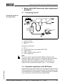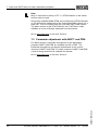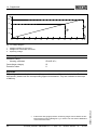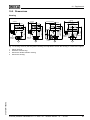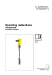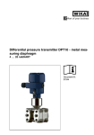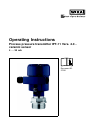
1
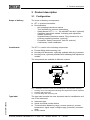
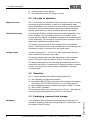
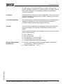
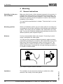
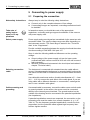
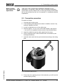
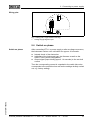
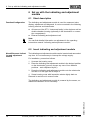
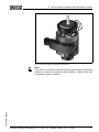
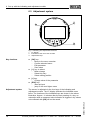
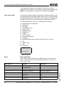
Operating Instructions
Process pressure transmitter IPT-11 Vers. 4.0 ceramic sensor
4 … 20 mA
Document ID:
37301
Contents
Contents
1
About this document
1.1
1.2
1.3
2
.
.
.
.
.
.
.
.
.
.
.
.
.
.
.
.
.
.
.
.
.
.
.
.
..
..
..
..
..
..
..
..
5
5
5
5
6
6
6
6
.
.
.
.
.
.
.
.
.
.
.
.
.
.
.
.
.
.
.
.
.
.
.
.
.
.
.
.
.
.
.
.
..
..
..
..
7
8
8
8
General instructions . . . . . . . . . . . . . . . . . . . . . . . . .
Mounting steps. . . . . . . . . . . . . . . . . . . . . . . . . . . . .
10
11
Configuration . . . . . . . . . . . . . . .
Principle of operation . . . . . . . . .
Operation. . . . . . . . . . . . . . . . . .
Packaging, transport and storage
.
.
.
.
.
.
.
.
.
.
.
.
.
.
.
.
.
.
.
.
Preparing the connection
Connection procedure. . .
Single chamber housing .
Switch on phase. . . . . . .
.
.
.
.
.
.
.
.
.
.
.
.
.
.
.
.
.
.
.
.
.
.
.
.
.
.
.
.
.
.
.
.
.
.
.
.
.
.
.
.
.
.
.
.
.
.
.
.
.
.
.
.
.
.
.
.
.
.
.
.
.
.
.
.
.
.
.
.
.
.
.
.
.
.
.
.
..
..
..
..
12
13
14
15
Short description . . . . . . . . . . . . . . . . .
Insert indicating and adjustment module.
Adjustment system . . . . . . . . . . . . . . . .
Setup procedure. . . . . . . . . . . . . . . . . .
Menu schematic . . . . . . . . . . . . . . . . . .
Saving the parameter adjustment data . .
.
.
.
.
.
.
.
.
.
.
.
.
.
.
.
.
.
.
.
.
.
.
.
.
.
.
.
.
.
.
.
.
.
.
.
.
.
.
.
.
.
.
.
.
.
.
.
.
..
..
..
..
..
..
16
16
18
19
28
30
Connecting the PC . . . . . . . . . . . . . . . . . . . . . . . . . .
Parameter adjustment with PACTware . . . . . . . . . . . .
Parameter adjustment with AMS™ and PDM . . . . . . .
31
31
32
Maintenance, cleaning . . . . . . . . . . . . . . . . . . . . . . .
Rectify malfunctions . . . . . . . . . . . . . . . . . . . . . . . . .
Instrument repair . . . . . . . . . . . . . . . . . . . . . . . . . . .
33
33
34
Process pressure transmitter IPT-11 Vers. 4.0 - ceramic sensor • 4 … 20 mA
37301-EN-100302
Maintenance and fault rectification
8.1
8.2
8.3
2
.
.
.
.
.
.
.
.
Setup with PACTware and other adjustment programs
7.1
7.2
7.3
8
.
.
.
.
.
.
.
.
Set up with the indicating and adjustment module
6.1
6.2
6.3
6.4
6.5
6.6
7
.
.
.
.
.
.
.
.
Connecting to power supply
5.1
5.2
5.3
5.4
6
.
.
.
.
.
.
.
.
Mounting
4.1
4.2
5
.
.
.
.
.
.
.
.
Authorised personnel . . . . . . . . . . . . . .
Appropriate use . . . . . . . . . . . . . . . . . .
Warning about misuse . . . . . . . . . . . . .
General safety instructions . . . . . . . . . .
Safety label on the instrument . . . . . . . .
CE conformity . . . . . . . . . . . . . . . . . . .
Fulfillment of NAMUR recommendations
Safety instructions for Ex areas . . . . . . .
Product description
3.1
3.2
3.3
3.4
4
4
4
4
For your safety
2.1
2.2
2.3
2.4
2.5
2.6
2.7
2.8
3
Function. . . . . . . . . . . . . . . . . . . . . . . . . . . . . . . . . .
Target group . . . . . . . . . . . . . . . . . . . . . . . . . . . . . .
Symbolism used. . . . . . . . . . . . . . . . . . . . . . . . . . . .
Contents
9
Dismounting
9.1
9.2
Dismounting steps . . . . . . . . . . . . . . . . . . . . . . . . . .
Removal . . . . . . . . . . . . . . . . . . . . . . . . . . . . . . . . .
36
36
10 Supplement
10.1 Technical data . . . . . . . . . . . . . . . . . . . . . . . . . . . . .
10.2 Dimensions . . . . . . . . . . . . . . . . . . . . . . . . . . . . . . .
37
45
Supplementary documentation
Information:
Supplementary documents appropriate to the ordered version come
with the delivery. You can find them listed in chapter "Product
description".
37301-EN-100302
Instructions manuals for accessories and replacement parts
Tip:
To ensure reliable setup and operation of your IPT-11, we offer
accessories and replacement parts. The corresponding documentations are:
l
Operating instructions manual "External indicating and adjustment
unit"
Process pressure transmitter IPT-11 Vers. 4.0 - ceramic sensor • 4 … 20 mA
3
1 About this document
1 About this document
1.1 Function
This operating instructions manual provides all the information you
need for mounting, connection and setup as well as important
instructions for maintenance and fault rectification. Please read this
information before putting the instrument into operation and keep this
manual accessible in the immediate vicinity of the device.
1.2 Target group
This operating instructions manual is directed to trained qualified
personnel. The contents of this manual should be made available to
these personnel and put into practice by them.
1.3 Symbolism used
Information, tip, note
This symbol indicates helpful additional information.
Caution: If this warning is ignored, faults or malfunctions can
result.
Warning: If this warning is ignored, injury to persons and/or serious
damage to the instrument can result.
Danger: If this warning is ignored, serious injury to persons and/or
destruction of the instrument can result.
Ex applications
This symbol indicates special instructions for Ex applications.
l
à
1
List
The dot set in front indicates a list with no implied sequence.
Action
This arrow indicates a single action.
Sequence
Numbers set in front indicate successive steps in a procedure.
37301-EN-100302
4
Process pressure transmitter IPT-11 Vers. 4.0 - ceramic sensor • 4 … 20 mA
2 For your safety
2 For your safety
2.1 Authorised personnel
Mount and set up the pressure transmitter only if you know the
applicable national regulations and have the appropriate qualification.
You must be aquainted with the regulations and instructions for
hazardous areas, measurement and control technology as well as
electrical circuits because the pressure transmitter is "electrical
equipment" according to EN 50178. Depending on the application
conditions, it is necessary that you have appropriate knowledge, e.g.
concerning corrosive products or high pressure.
2.2 Appropriate use
IPT-11 is a pressure transmitter for measurement of gauge pressure,
absolute pressure and vacuum.
You can find detailed information on the application range in chapter
"Product description".
Operational reliability is ensured only if the instrument is properly used
according to the specifications in the operating instructions manual as
well as possible supplementary instructions.
For safety and warranty reasons, any invasive work on the device
beyond that described in the operating instructions manual may be
carried out only by personnel authorised by the manufacturer. Arbitrary
conversions or modifications are explicitly forbidden.
2.3 Warning about misuse
Inappropriate or incorrect use of the instrument can give rise to
application-specific hazards, e.g. vessel overfill or damage to system
components through incorrect mounting or adjustment.
2.4 General safety instructions
This is a high-tech instrument requiring the strict observance of
standard regulations and guidelines. The user must take note of the
safety instructions in this operating instructions manual, the countryspecific installation standards as well as all prevailing safety
regulations and accident prevention rules.
37301-EN-100302
The instrument must only be operated in a technically flawless and
reliable condition. The operator is responsible for trouble-free
operation of the instrument.
During the entire duration of use, the user is obliged to determine the
compliance of the required occupational safety measures with the
current valid rules and regulations and also take note of new
regulations.
Process pressure transmitter IPT-11 Vers. 4.0 - ceramic sensor • 4 … 20 mA
5
2 For your safety
2.5 Safety label on the instrument
The safety approval markings and safety tips on the device must be
observed.
2.6 CE conformity
This device fulfills the legal requirements of the applicable EC
guidelines. By attaching the CE mark, we provide confirmation of
successful testing.
2.7 Fulfillment of NAMUR recommendations
The device fulfills the requirements of the applicable NAMUR
recommendations.
2.8 Safety instructions for Ex areas
Please note the Ex-specific safety information for installation and
operation in Ex areas. These safety instructions are part of the
operating instructions manual and come with the Ex-approved
instruments.
37301-EN-100302
6
Process pressure transmitter IPT-11 Vers. 4.0 - ceramic sensor • 4 … 20 mA
3 Product description
3 Product description
3.1 Configuration
Scope of delivery
The scope of delivery encompasses:
l
l
Constituents
IPT-11 pressure transmitter
Documentation
- this operating instructions manual
- Test certificate for pressure transmitters
- Safety Manual "IPT-1* - 4 … 20 mA/HART two-wire" (optional)
- Operating instructions manual "Indicating and adjustment
module" (optional)
- Supplementary instructions manual "Plug connector for continuously measuring sensors" (optional)
- Ex-specific "Safety instructions" (with Ex versions)
- if necessary, further certificates
The IPT-11 consist of the following components:
l
l
l
Process fitting with measuring cell
Housing with electronics, optionally available with plug connector
Housing cover, optionally available with indicating and adjustment
module
The components are available in different versions.
1
2
3
Fig. 1: Example of a IPT-11 with process fitting G1½ A and plastic housing
1
2
3
37301-EN-100302
Type label
Housing cover with integrated indicating and adjustment module (optional)
Housing with electronics
Process fitting with measuring cell
The type label contains the most important data for identification and
use of the instrument:
l
l
l
l
Instrument type
Article and serial number device
Technical data: Measuring range, process pressure, process
temperature, signal output, voltage supply, protection, protection
class
Order number
Process pressure transmitter IPT-11 Vers. 4.0 - ceramic sensor • 4 … 20 mA
7
3 Product description
l
l
Article number, documentation
SIL identification (with SIL rating ex works)
3.2 Principle of operation
Application area
IPT-11 is a pressure transmitter for use in the paper, food processing
and pharmaceutical industries as well as in water/sewage water
plants. Depending on the version, it is used for level, gauge, absolute
pressure or vacuum measurement. Measured products are gases,
vapours and liquids, also those containing abrasive substances.
Functional principle
A measuring cell with front-flush, abrasion-resistant diaphragm is the
sensor element. The hydrostatic pressure of the product or the
process pressure effects a capacitance change in the measuring cell
via the diaphragm. This change is converted into a respective output
signal and outputted as measured value.
The ceramic measuring cell is also equipped with a temperature
sensor. The temperature value can be displayed via the indicating and
adjustment module or processed via the signal output.
Voltage supply
Two-wire electronics 4 … 20 mA for power supply and measured
value transmission over the same cable.
The supply voltage range can differ depending on the instrument
version. The exact range is stated in chapter "Technical data".
The background lighting of the indicating and adjustment module is
powered by the sensor. A certain level of operating voltage is required
for this. You can find the exact voltage specifications in chapter
"Technical data".
3.3 Operation
IPT-11 can be adjusted with different adjustment media:
l
l
l
l
with indicating and adjustment module
the suitable WIKA DTM in conjunction with an adjustment software
according to the FDT/DTM standard, e.g. PACTware and PC
with manufacturer-specific adjustment programs AMS™ or PDM
With a HART handheld
The entered parameters are generally saved in IPT-11, optionally also
in the indicating and adjustment module or in PACTware.
3.4 Packaging, transport and storage
Packaging
Process pressure transmitter IPT-11 Vers. 4.0 - ceramic sensor • 4 … 20 mA
37301-EN-100302
8
Your instrument was protected by packaging during transport. Its
capacity to handle normal loads during transport is assured by a test
according to DIN EN 24180.
3 Product description
The packaging of standard instruments consists of environmentfriendly, recyclable cardboard. For special versions, PE foam or PE foil
is also used. Dispose of the packaging material via specialised
recycling companies.
Transport
Transport must be carried out under consideration of the notes on the
transport packaging. Nonobservance of these instructions can cause
damage to the device.
Transport inspection
The delivery must be checked for completeness and possible transit
damage immediately at receipt. Ascertained transit damage or
concealed defects must be appropriately dealt with.
Storage
Up to the time of installation, the packages must be left closed and
stored according to the orientation and storage markings on the
outside.
Unless otherwise indicated, the packages must be stored only under
the following conditions:
Storage and transport
temperature
l
l
l
l
l
Not in the open
Dry and dust free
Not exposed to corrosive media
Protected against solar radiation
Avoiding mechanical shock and vibration
l
Storage and transport temperature see chapter "Supplement Technical data - Ambient conditions"
Relative humidity 20 … 85 %
37301-EN-100302
l
Process pressure transmitter IPT-11 Vers. 4.0 - ceramic sensor • 4 … 20 mA
9
4 Mounting
4 Mounting
4.1 General instructions
Suitability for the process conditions
Make sure that all parts of the instrument exposed to the process, in
particular the sensor element, process seal and process fitting, are
suitable for the existing process conditions. These include above all
the process pressure, process temperature as well as the chemical
properties of the medium.
You can find the specifications in chapter "Technical data" or on the
type label.
Mounting position
Select an installation position you can easily reach for mounting and
connecting as well as later retrofitting of an indicating and adjustment
module. The housing can be rotated by 330° without the use of any
tools. You can also install the indicating and adjustment module in four
different positions (each displaced by 90°).
Moisture
Use the recommended cables (see chapter "Connecting to power
supply") and tighten the cable gland.
You can give your instrument additional protection against moisture
penetration by leading the connection cable downward in front of the
cable entry. Rain and condensation water can thus drain off. This
applies mainly to outdoor mounting as well as installation in areas
where high humidity is expected (e.g. through cleaning processes) or
on cooled or heated vessels.
Fig. 2: Measures against moisture penetration
10
The ventilation for the electronics housing is realised via a filter
element in the vicinity of the cable glands.
Process pressure transmitter IPT-11 Vers. 4.0 - ceramic sensor • 4 … 20 mA
37301-EN-100302
Ventilation
4 Mounting
Fig. 3: Position of the filter element with single and double chamber housing
1
2
Filter element for ventilation of the electronics housing
Blind stopper
Information:
Make sure that the filter element is always free of buildup during
operation. A high-pressure cleaner must not be used for cleaning.
Temperature limits
Higher process temperatures mean often also higher ambient
temperatures.
2
1
Fig. 4: Temperature ranges
1
2
Process temperature
Ambient temperature
Make sure that the upper temperature limits for the environment of
electronics housing and connection cable specified in chapter
"Technical data" are not exceeded.
4.2 Mounting steps
Welding the socket
To mount IPT-11, a welded socket is necessary. Use components
from the line of WIKA mounting accessories:
37301-EN-100302
à Note the applicable welding standards (segment welding procedure) when welding the socket.
Sealing/Screwing in hygienic fittings
Use the seal corresponding to the process fitting.
Process pressure transmitter IPT-11 Vers. 4.0 - ceramic sensor • 4 … 20 mA
11
5 Connecting to power supply
5 Connecting to power supply
5.1 Preparing the connection
Note safety instructions
Always keep in mind the following safety instructions:
l
l
Connect only in the complete absence of line voltage
If overvoltage surges are expected, overvoltage arresters should
be installed
Take note of
safety instructions for Ex applications
In hazardous areas you should take note of the appropriate
regulations, conformity and type approval certificates of the sensors
and power supply units.
Select power supply
Power supply and current signal are transmitted via the same two-wire
connection cable. The supply voltage range can differ depending on
the instrument version. The exact range is stated in the "Technical
data" in the "Supplement".
Provide a reliable separation between the supply circuit and the mains
circuits according to DIN VDE 0106 part 101.
Keep in mind the following additional influences on the operating
voltage:
l
l
Selecting connection
cable
Output voltage of the power supply unit can be lower under
nominal load (with a sensor current of 20.5 mA or 22 mA in case of
fault message)
Influence of additional instruments in the circuit (see load values in
chapter "Technical data")
The instrument is connected with standard two-wire cable without
screen. If electromagnetic interference is expected which is above the
test values of EN 61326 for industrial areas, screened cable should be
used.
Use cable with round cross-section. A cable outer diameter of 5 … 9 mm
(0.2 … 0.35 in) ensures the seal effect of the cable gland. If you are
using cable with a different diameter or cross-section, exchange the
seal or use a suitable cable gland.
Cable screening and
grounding
If screened cable is necessary, connect the cable screen on both ends
to ground potential. In the sensor, the screen must be connected
directly to the internal ground terminal. The ground terminal on the
outside of the housing must be connected to the potential equalisation
(low impedance).
12
Process pressure transmitter IPT-11 Vers. 4.0 - ceramic sensor • 4 … 20 mA
37301-EN-100302
If potential equalisation currents are expected, the connection on the
processing side must be made via a ceramic capacitor (e. g. 1 nF,
1500 V). The low frequency potential equalisation currents are thus
suppressed, but the protective effect against high frequency interference signals remains.
5 Connecting to power supply
Select connection cable for Ex
applications
Take note of the corresponding installation regulations for Ex
applications. In particular, make sure that no potential equalisation
currents flow over the cable screen. In case of grounding on both sides
this can be achieved by the use of a capacitor or a separate potential
equalisation.
5.2 Connection procedure
37301-EN-100302
Proceed as follows:
1
Unscrew the housing cover
2
If an indicating and adjustment module is installed, remove it by
turning it slightly to the left.
3
Loosen compression nut of the cable entry
4
Remove approx. 10 cm (4 in) of the cable mantle, strip approx.
1 cm (0.4 in) of insulation from the ends of the individual wires
5
Insert the cable through the cable gland into the sensor
6
Lift the opening levers of the terminals with a screwdriver (see
following illustration)
7
Insert the wire ends into the open terminals according to the wiring
plan
Fig. 5: Connection steps 6 and 7
8
Press down the opening levers of the terminals, you will hear the
terminal spring closing
Process pressure transmitter IPT-11 Vers. 4.0 - ceramic sensor • 4 … 20 mA
13
5 Connecting to power supply
9
Check the hold of the wires in the terminals by lightly pulling on
them
10 Connect the screen to the internal ground terminal, connect the
outer ground terminal with potential equalisation
11 Tighten the compression nut of the cable entry. The seal ring must
completely encircle the cable
12 Screw the housing cover on
The electrical connection is finished.
5.3 Single chamber housing
Electronics and connection compartment
4...20mA
1
1
Display
2
2
Fig. 6: Electronics and connection compartment with single chamber housing
1
2
Spring-loaded terminals for voltage supply
Ground terminal for connection of the cable screen
37301-EN-100302
14
Process pressure transmitter IPT-11 Vers. 4.0 - ceramic sensor • 4 … 20 mA
5 Connecting to power supply
Wiring plan
4...20mA
1
Display
2
1
Fig. 7: Wiring plan, single chamber housing
1
Voltage supply/Signal output
5.4 Switch on phase
Switch on phase
After connecting IPT-11 to power supply or after a voltage recurrence,
the instrument carries out a self-check for approx. 30 seconds:
l
l
l
Internal check of the electronics
Indication of the instrument type, the firmware as well as the
sensor TAGs (sensor designation)
Output signal jumps briefly (approx. 10 seconds) to the set fault
current
37301-EN-100302
Then the corresponding current is outputted to the cable (the value
corresponds to the actual level as well as the settings already carried
out, e.g. factory setting).
Process pressure transmitter IPT-11 Vers. 4.0 - ceramic sensor • 4 … 20 mA
15
6 Set up with the indicating and adjustment module
6 Set up with the indicating and adjustment
module
6.1 Short description
Function/Configuration
The indicating and adjustment module is used for measured value
display, adjustment and diagnosis. It can be mounted in the following
housing versions and instruments:
l
l
All sensors of the IPT-1* instrument family, in the single as well as
double chamber housing (optionally in the electronics or connection compartment)
External indicating and adjustment unit
Note:
You can find detailed information on adjustment in the operating
instructions manual "Indicating and adjustment module".
6.2 Insert indicating and adjustment module
Mount/Dismount indicating and adjustment
module
The indicating and adjustment module can be inserted and removed at
any time. It is not necessary to interrupt the voltage supply.
For installation, proceed as follows:
1
Unscrew the housing cover
2
Place the indicating and adjustment module in the desired position
on the electronics (you can choose any one of four different
positions - each displaced by 90°)
3
Press the indicating and adjustment module onto the electronics
and turn it to the right until it snaps in.
4
Screw housing cover with inspection window tightly back on
Removal is carried out in reverse order.
The indicating and adjustment module is powered by the sensor, an
additional connection is not necessary.
37301-EN-100302
16
Process pressure transmitter IPT-11 Vers. 4.0 - ceramic sensor • 4 … 20 mA
6 Set up with the indicating and adjustment module
Fig. 8: Insert indicating and adjustment module
37301-EN-100302
Note:
If you intend to retrofit the instrument with an indicating and adjustment
module for continuous measured value indication, a higher cover with
an inspection glass is required.
Process pressure transmitter IPT-11 Vers. 4.0 - ceramic sensor • 4 … 20 mA
17
6 Set up with the indicating and adjustment module
6.3 Adjustment system
2
1
1.1
3
Fig. 9: Indicating and adjustment elements
Key functions
Adjustment system
1
2
3
LC display
Indication of the menu item number
Adjustment keys
l
[OK] key:
- Move to the menu overview
- Confirm selected menu
- Edit parameter
- Save value
l
[->] key to select:
- Menu change
- Select list entry
- Select editing position
l
[+] key:
- Change value of the parameter
l
[ESC] key:
- interrupt input
- jump to the next higher menu
The sensor is adjusted via the four keys of the indicating and
adjustment module. The LC display indicates the individual menu
items. The functions of the individual keys are shown in the above
illustration. Approx. 10 minutes after the last pressing of a key, an
automatic reset to measured value indication is triggered. Any values
not confirmed with [OK] will not be saved.
37301-EN-100302
18
Process pressure transmitter IPT-11 Vers. 4.0 - ceramic sensor • 4 … 20 mA
6 Set up with the indicating and adjustment module
6.4 Setup procedure
Level or process pressure measurement
IPT-11 can be used for level as well as for process pressure
measurement. Default setting is level measurement. The mode can be
changed in the adjustment menu.
Depending on the application only the respective subchapter "Level or
process pressure measurement" is of importance. There, you find the
individual adjustment steps.
Level measurement
Parameter adjustment "Level
measurement"
Set up IPT-11 in the following sequence:
1
Selecting adjustment unit/density unit
2
Carry out position correction
3
Carrying out min. adjustment
4
Carrying out max. adjustment
In the menu item "Adjustment unit" you select the physical unit in which
the adjustment should be carried out, e.g. mbar, bar, psi…
The position correction compensates the influence of the mounting
position or static pressure on the measurement. It does not influence
the adjustment values.
Information:
The steps 1, 3 and 4 are not necessary for instruments which are
already preset according to customer specifications!
You can find the data on the type label on the instrument or in the
menu items of the min./max. adjustment.
The indicating and adjustment module enables the adjustmetn without
filling or pressure. Thanks to this, you can carry out your settings
already in the factory without the instrument having to be installed.
The actual measured value is also displayed in the menu items for
min./max. adjustment.
Select unit
In this menu item you select the adjustment unit as well as the unit for
the temperature indication in the display.
37301-EN-100302
To select the adjustment unit (in the example switching over from bar
to mbar), proceed as follows:1)
1
Push the [OK] button in the measured value display, the menu
overview is displayed.
1)
Selection options: mbar, bar, psi, Pa, kPa, MPa, inHg, mmHg, inH2O,
mmH2O.
Process pressure transmitter IPT-11 Vers. 4.0 - ceramic sensor • 4 … 20 mA
19
6 Set up with the indicating and adjustment module
▶
2
Basic adjustment
Display
Diagnostics
Service
Info
Confirm the menu "Basic adjustment" with [OK], the menu item
"Unit" will be displayed.
Unit
Unit of measurement
bar▼
Temperature unit
°C▼
3
Activate the selection with [OK] and select "Units of measurement with [->].
4
Activate the selection with [OK] and select the requested unit with
[->] (in the example mbar).
5
Confirm with [OK] and move to position correction with [->].
The adjustment unit is thus switched over from bar to mbar.
Information:
When switching over to adjustment in a height unit (in the example
from bar to m), the density also has to be entered.
Proceed as follows:
1
Push the [OK] button in the measured value display, the menu
overview is displayed.
2
Confirm the menu "Basic adjustment" with [OK], the menu item
"Units of measurement" will be displayed.
3
Activate the selection with [OK] and select the requested unit with
[->] (in the example m).
4
Confirm with [OK], the submenu "Density unit" appears.
Unit of measurement
▶
5
Density unit
kg/dm³
pcf
Select the requested unit, e.g. kg/dm³ with [->] and confirm with
[OK], the submenu "Density" appears.
Unit of measurement
6
20
Enter the requested density value with [->] and [+], confirm with
[OK] and move to position correction with [->].
Process pressure transmitter IPT-11 Vers. 4.0 - ceramic sensor • 4 … 20 mA
37301-EN-100302
Density
0001000
kg/dm³
6 Set up with the indicating and adjustment module
The adjustment unit is thus switched over from bar to m.
Proceed as follows to select the temperature unit:2)
à Activate the selection with [OK] and select "Temperature unit
with [->].
à Activate the selection with [OK] and select the requested unit with
[->] (e.g. °F).
à Confirm with [OK].
The temperature unit is hence switched over from °C to °F.
Carry out position correction
Proceed as follows:
1
Activate in the menu item "Position correction" the selection with
[OK].
Position correction
Offset
=
+0000 mbar
53 mbar
2
▶
3
Carrying out min. adjustment
P
Select with [->], e.g. to accept actual measured value.
Position correction
Accept current measured
value?
Accept
Edit
Confirm with [OK] and move to min.(zero) adjustment with [->].
Proceed as follows:
1
Edit the % value in the menu item "Min. adjustment" with [OK].
Min. adjustment
+000.0 %
=
+0000.0 mbar
0000.0 mbar
2
Set the requested percentage value with [+] and [->].
3
Edit the requested mbar value with [OK].
4
Set the requested mbar value with [+] and [->].
5
Confirm with [+] and move to max. adjustment with [->].
37301-EN-100302
The min. adjustment is finished.
Information:
For an adjustment with filling, simply enter the actual measured value
indicated at the bottom of the display.
2)
Selection options: °C, °F.
Process pressure transmitter IPT-11 Vers. 4.0 - ceramic sensor • 4 … 20 mA
21
6 Set up with the indicating and adjustment module
If the adjustment ranges are exceeded, the message "Outside
parameter limits" appears. The editing procedure can be aborted with
[ESC] or the displayed limit value can be accepted with [OK].
Carrying out max. adjustment
Proceed as follows:
1
Edit the % value in the menu item "Max. adjustment" with [OK].
Max. adjustment
+100.0 %
=
+1000.0 mbar
0000.0 mbar
Information:
The displayed pressure for 100 % corresponds to the nominal
measuring range of the sensor (in the above example 1 bar =
1000 mbar).
2
Set the requested percentage value with [->] and [OK].
3
Edit the requested mbar value with [OK].
4
Set the requested mbar value with [+] and [->].
5
Confirm with [OK] and move to the menu overview with [ESC].
The max. adjustment is finished.
Information:
For an adjustment with filling, simply enter the actual measured value
indicated at the bottom of the display.
If the adjustment ranges are exceeded, the message "Outside
parameter limits" appears. The editing procedure can be aborted with
[ESC] or the displayed limit value can be accepted with [OK].
Process pressure measurement
Parameter adjustment "Process pressure
measurement"
Set up IPT-11 in the following sequence:
1
Select application "Process pressure measurement"
2
Select the unit of measurement
3
Carry out position correction
4
Carrying out zero adjustment
5
Carrying out span adjustment
In the menu item "Adjustment unit" you select the physical unit in which
the adjustment should be carried out, e.g. mbar, bar, psi…
22
Process pressure transmitter IPT-11 Vers. 4.0 - ceramic sensor • 4 … 20 mA
37301-EN-100302
The position correction compensates the influence of the mounting
position or static pressure on the measurement. It does not influence
the adjustment values.
6 Set up with the indicating and adjustment module
In the menu items "zero" and "span" you determine the span of the
sensor, the span corresponds to the end value.
Information:
The steps 1, 3 and 4 are not necessary for instruments which are
already preset according to customer specifications!
You can find the data on the type label on the instrument or in the
menu items of the zero/span adjustment.
The indicating and adjustment module enables the adjustmetn without
filling or pressure. Thanks to this, you can carry out your settings
already in the factory without the instrument having to be installed.
The actual measured value is displayed in addition to the menu items
for zero/span adjustment.
Select application
"Process pressure
measurement"
IPT-11 is preset to application "Level measurement". Proceed as
follows when switching over to application "Process pressure
measurement":
1
2
▶
3
Push the [OK] button in the measured value display, the menu
overview is displayed.
Select the menu "Service" with [->] and confirm with [OK].
Basic adjustment
Display
Diagnostics
Service
Info
Select the menu item "Application" with [->] and edit with [OK].
Warning:
Note the warning: "Output can change".
Select unit
4
Select with [->] "OK" and confirm with [OK].
5
Select "Process pressure" from the list and confirm with [OK].
In this menu item you select the adjustment unit as well as the unit for
the temperature indication in the display.
37301-EN-100302
To select the adjustment unit (in the example switching over from bar
to mbar), proceed as follows:3)
1
Push the [OK] button in the measured value display, the menu
overview is displayed.
3)
Selection options: mbar, bar, psi, Pa, kPa, MPa, inHg, mmHg, inH2O,
mmH2O.
Process pressure transmitter IPT-11 Vers. 4.0 - ceramic sensor • 4 … 20 mA
23
6 Set up with the indicating and adjustment module
▶
2
Basic adjustment
Display
Diagnostics
Service
Info
Confirm the menu "Basic adjustment" with [OK], the menu item
"Unit" will be displayed.
Unit
Unit of measurement
bar▼
Temperature unit
°C▼
3
Activate the selection with [OK] and select "Units of measurement with [->].
4
Activate the selection with [OK] and select the requested unit with
[->] (in the example mbar).
5
Confirm with [OK] and move to position correction with [->].
The adjustment unit is thus switched over from bar to mbar.
Proceed as follows to select the temperature unit:4)
à Activate the selection with [OK] and select "Temperature unit
with [->].
à Activate the selection with [OK] and select the requested unit with
[->] (e.g. °F).
à Confirm with [OK].
The temperature unit is hence switched over from °C to °F.
Carry out position correction
Proceed as follows:
1
Activate in the menu item "Position correction" the selection with
[OK].
Position correction
Offset
=
+0000 mbar
53 mbar
2
▶
Select with [->], e.g. to accept actual measured value.
Position correction
Accept current measured
value?
Accept
Edit
3
Confirm with [OK] and move to min.(zero) adjustment with [->].
4)
Selection options: °C, °F.
Process pressure transmitter IPT-11 Vers. 4.0 - ceramic sensor • 4 … 20 mA
37301-EN-100302
24
P
6 Set up with the indicating and adjustment module
Carrying out zero adjustment
Proceed as follows:
1
Edit the mbar value in the menu item "zero" with [OK].
Zero
000.0 %
=
+0000.0 mbar
0000.0 mbar
P
2
Set the requested mbar value with [+] and [->].
3
Confirm with [+] and move to span adjustment with [->].
The zero adjustment is finished.
Information:
The zero adjustment shifts the value of the span adjustment. The span,
i.e. the difference between these values, however, remains unchanged.
Information:
For an adjustment with pressure, simply enter the actual measured
value indicated at the bottom of the display.
If the adjustment ranges are exceeded, the message "Outside
parameter limits" appears. The editing procedure can be aborted with
[ESC] or the displayed limit value can be accepted with [OK].
Carrying out span adjustment
Proceed as follows:
1
Edit the mbar value in the menu item "span" with [OK].
Span
100.0 %
=
+1000.0 mbar
0000.0 mbar
P
Information:
The displayed pressure for 100 % corresponds to the nominal
measuring range of the sensor (in the above example 1 bar =
1000 mbar).
2
Set the requested mbar value with [->] and [OK].
3
Confirm with [OK] and move to the menu overview with [ESC].
37301-EN-100302
The span adjustment is finished.
Information:
For an adjustment with pressure, simply enter the actual measured
value indicated at the bottom of the display.
Process pressure transmitter IPT-11 Vers. 4.0 - ceramic sensor • 4 … 20 mA
25
6 Set up with the indicating and adjustment module
If the adjustment ranges are exceeded, the message "Outside
parameter limits" appears. The editing procedure can be aborted with
[ESC] or the displayed limit value can be accepted with [OK].
Copy sensor data
This function enables reading out parameter adjustment data as well
as writing parameter adjustment data into the sensor via the indicating
and adjustment module. A description of the function is available in the
operating instructions manual "Indicating and adjustment module".
The following data are read out or written with this function:
l
l
l
l
l
l
l
l
l
l
l
Measured value presentation
Adjustment
Damping
Linearisation curve
Sensor-TAG
Displayed value
Display unit
Scaling
Current output
Unit of measurement
Language
The following safety-relevant data are not read out or written:
l
l
l
l
SIL
HART mode
PIN
Application
Copy sensor data
Copy sensor data?
Reset
Menu section
Basic settings
Function
Reset value
Unit of measurement
bar
Temperature unit
°C
Zero/Min. adjustment
Measuring range begin
Span/Max. adjustment
Measuring range end
Density
1 kg/l
Density unit
kg/l
Damping
1s
Linearisation
linear
Process pressure transmitter IPT-11 Vers. 4.0 - ceramic sensor • 4 … 20 mA
37301-EN-100302
26
Basic adjustment
If the "Reset" (sensor-specific basic adjustment) is carried out, the
sensor resets the values of the following menu items to the reset
values (see chart):
6 Set up with the indicating and adjustment module
Menu section
Display
Service
Function
Reset value
Sensor-TAG
Sensor
Displayed value 1
bar
Displayed value 2
%
Display unit
Volume/l
Scaling
0.00 to 100.0
Decimal point indication
8888.8
Current output - characteristics
4 … 20 mA
Current output - failure
< 3.6 mA
Current output - min. current
3.8 mA
Current output - max. current
20.5 mA
The values of the following menu items are not reset with "Reset:
Menu section
Function
Reset value
Basic settings
Position correction
no reset
Display
Lighting
no reset
Service
SIL
no reset
Language
no reset
HART mode
no reset
Application
no reset
Factory setting
Like basic adjustment, in addition, special parameters are reset to
default values.5)
Pointer
The min. and max. temperature or pressure values are each reset to
the actual value.
37301-EN-100302
Optional settings
Additional adjustment and diagnosis options such as e.g. scaling,
simulation or trend curve presentation are shown in the following menu
schematic. You will find a detailed description of these menu items in
the operating instructions manual "Indicating and adjustment module".
5)
Special parameters are parameters which are set customer-specifically on
the service level with the adjustment software PACTware.
Process pressure transmitter IPT-11 Vers. 4.0 - ceramic sensor • 4 … 20 mA
27
6 Set up with the indicating and adjustment module
6.5 Menu schematic
Information:
Depending on the version and application, the highlighted menu
windows may not always be available.
Basic adjustment
▶
Basic adjustment
Display
Diagnostics
Service
Info
1
Unit
Unit of measurement
bar▼
Temperature unit
°C▼
1.1
Damping
1.5
Position correction
Offset
=
0.2 mbar
0000 mbar
1.2
Linearisation curve
1.6
P
linear ▼
1s
Min. adjustment
000.0 %
=
0.0 mbar
0.0 mbar
1.3
Sensor-TAG
1.7
Max. adjustment
100.00 %
=
100.00 mbar
0.0 mbar
1.4
Scaling
0 % = 0.0
l
100 % = 100.0
l
2.3
Sensor
Display
▶
Basic adjustment
Display
Diagnostics
Service
Info
Displayed value
2
2.1
Pressure ▼
Lighting
Displayed value ▼
Scaled
2.1
Display unit
Volume ▼
l▼
2.2
2.4
Switched off ▼
37301-EN-100302
28
Process pressure transmitter IPT-11 Vers. 4.0 - ceramic sensor • 4 … 20 mA
6 Set up with the indicating and adjustment module
Diagnostics
▶
Basic adjustment
Display
Diagnostics
Service
Info
Pointer
p-min.: -5.8 mbar
p-max.: 167.5 mbar
T-min.: -12.5 °C
T-max.: +85.5 °C
3
3.1
Sensor status
3.2
OK
Trend curve
3.3.1
Start trend curve?
Service
▶
Basic adjustment
Display
Diagnostics
Service
Info
Current output
4
4.1
Output mode: 4-20 mA ▼
Fail.mode: < 3.6 mA ▼
Min. current: 3.8 mA ▼
max. current: 20.5 mA ▼
Copy sensor data
Simulation
4.2
Start simulation ▼
4.7
Copy sensor data?
4.3
Select reset ▼
4.8
PIN
Reset
Application
Language
4.4
Deutsch ▼
4.9
Level ▼
Enable?
Info
▶
Basic adjustment
Display
Diagnostics
Service
Info
Instrument type
5.1
Date of manufacture
1st October 2009
Software version
3.80
5.2
Last change using PC
5.3
Sensor characteristics
5.4
Display now?
1st October 2009
37301-EN-100302
Serial number
12345678
5
Process pressure transmitter IPT-11 Vers. 4.0 - ceramic sensor • 4 … 20 mA
29
6 Set up with the indicating and adjustment module
6.6 Saving the parameter adjustment data
It is recommended noting the adjusted data, e.g. in this operating
instructions manual and archive them afterwards. They are hence
available for multiple use or service purposes.
If IPT-11 is equipped with an indicating and adjustment module, the
most important data can be read out of the sensor into indicating and
adjustment module. The procedure is described in the operating
instructions manual "Indicating and adjustment module" in the menu
item "Copy sensor data". The data remain there permanently even if
the sensor power supply fails.
If it is necessary to exchange the sensor, the indicating and adjustment
module is inserted into the replacement instrument and the data are
written into the sensor under the menu item "Copy sensor data".
37301-EN-100302
30
Process pressure transmitter IPT-11 Vers. 4.0 - ceramic sensor • 4 … 20 mA
7 Setup with PACTware and other adjustment programs
7 Setup with PACTware and other adjustment
programs
7.1 Connecting the PC
Connecting the PC to
the signal cable
=
2
~
3
Power supply
HARTModem
PACTwareTM /
DTM
1
Fig. 10: Connecting the PC to the signal cable
1
2
3
RS232 connection
HART resistor 250 Ω
IPT-11 3
Necessary components:
l
l
l
l
l
IPT-11
PC with PACTware and suitable WIKA DTM
HART modem
HART resistance approx. 250 Ω
Power supply unit
Note:
For power supply units with integrated HART resistance (inner
resistance approx. 250 Ω), there is no additional external resistance
necessary. Standard Ex separators are often provided with a
sufficiently high current limitation resistance. In such cases, the
modem can be connected in parallel to the 4 … 20 mA cable.
37301-EN-100302
7.2 Parameter adjustment with PACTware
Further setup steps are described in the operating instructions manual
"DTM Collection/PACTware" attached to each CD and which can also
be downloaded from our homepage. A detailed description is available
in the online help of PACTware and the WIKA DTMs.
Process pressure transmitter IPT-11 Vers. 4.0 - ceramic sensor • 4 … 20 mA
31
7 Setup with PACTware and other adjustment programs
Note:
Keep in mind that for setup of IPT-11, DTM-Collection in the actual
version must be used.
All currently available WIKA DTMs are provided in the DTM Collection
on CD and can be obtained from the responsible WIKA agency for a
token fee. This CD includes also the up-to-date PACTware version.
The basic version of this DTM Collection incl. PACTware is also
available as a free-of-charge download from the Internet.
Go via www.wika.com to the item "Service".
7.3 Parameter adjustment with AMS™ and PDM
For WIKA sensors, instrument descriptions for the adjustment
programs AMS™ and PDM are available as DD or EDD. The
instrument descriptions are already implemented in the current
versions of AMS™ and PDM. For older versions of AMS™ and PDM,
a free-of-charge download is available via Internet.
Go via www.wika.com to the item "Service".
37301-EN-100302
32
Process pressure transmitter IPT-11 Vers. 4.0 - ceramic sensor • 4 … 20 mA
8 Maintenance and fault rectification
8 Maintenance and fault rectification
8.1 Maintenance, cleaning
When the instrument is used properly, no special maintenance is
required in normal operation.
In some applications, product buildup on the sensor diaphragm can
influence the measuring result. Depending on the sensor and
application, take precautions to ensure that heavy buildup, and
especially a hardening thereof, is avoided.
If necessary, the transmitter has to be cleaned. In this case, make sure
that the materials are resistant against the cleaning detergents.
8.2 Rectify malfunctions
Reaction when malfunctions occur
The operator of the system is responsible for taking suitable measures
to remove interferences.
Causes of malfunction
IPT-11 offers maximum reliability. Nevertheless, faults can occur
during operation. These may be caused by the following, e.g.:
l
l
l
l
Sensor
Process
Voltage supply
Signal processing
Fault rectification
The first measures to be taken are to check the output signals as well
as to evaluate the error messages via the indicating and adjustment
module. The procedure is described below. Further comprehensive
diagnostics can be carried out on a PC with the software PACTware
and the suitable DTM. In many cases, the causes can be determined
this way and faults rectified.
Checking the 4 … 20 mA
signal
Connect a handheld multimeter in the suitable measuring range
according to the wiring plan.
? 4 … 20 mA signal not stable
l
Level fluctuations
à Set the integration time via the indicating and adjustment
module or PACTware
37301-EN-100302
l
no atmospheric pressure compensation
à Check the pressure compensation in the housing and clean
the filter element, if necessary
Process pressure transmitter IPT-11 Vers. 4.0 - ceramic sensor • 4 … 20 mA
33
8 Maintenance and fault rectification
? 4 … 20 mA signal missing
l
Connection to voltage supply wrong
à Check connection according to chapter "Connection steps"
and if necessary, correct according to chapter "Wiring plan"
l
No power supply
à Check cables for breaks; repair if necessary
l
Operating voltage too low or load resistance too high
à Check, adapt if necessary
? Current signal greater than 22 mA or less than 3.6 mA
l
electronics module or measuring cell defective
à Exchange the instrument or send it for repair
In Ex applications, the regulations for the wiring of intrinsically safe
circuits must be observed.
Fault messages via the
indicating/adjustment
module
? E013
l
no measured value available6)
à Exchange the instrument or send it for repair
? E017
l
Adjustment span too small
à repeat with modified values
? E036
l
no operable sensor software
à Carry out a software update or send instrument for repair
? E041
l
Hardware error
à Exchange the instrument or send it for repair
Reaction after fault rectification
Depending on the failure reason and measures taken, the steps
described in chapter "Set up" must be carried out again, if necessary.
8.3 Instrument repair
You can download a return form (24 KB) in the Internet from our
homepage www.wika.com under the item "Service".
34
l
Print and fill out one form per instrument
6)
Fault message can also appear if the pressure is higher than the nominal
range.
Process pressure transmitter IPT-11 Vers. 4.0 - ceramic sensor • 4 … 20 mA
37301-EN-100302
If a repair is necessary, please proceed as follows:
8 Maintenance and fault rectification
l
l
l
l
If necessary, state a contamination
Clean the instrument and pack it damage-proof
Attach the completed form and probably a safety data sheet to the
instrument
Please contact the agency serving you for the address of the
return shipment
37301-EN-100302
By doing this you help us carry out the repair quickly and without
having to call back for needed information.
Process pressure transmitter IPT-11 Vers. 4.0 - ceramic sensor • 4 … 20 mA
35
9 Dismounting
9 Dismounting
9.1 Dismounting steps
Warning:
Before dismounting, be aware of dangerous process conditions such
as e.g. pressure in the vessel, high temperatures, corrosive or toxic
products etc.
Take note of chapters "Mounting" and "Connecting to power supply"
and carry out the listed steps in reverse order.
9.2 Removal
Note:
When disposing of old instruments, take note of the valid legal and
municipal regulations. The appropriate parts must be recycled.
37301-EN-100302
36
Process pressure transmitter IPT-11 Vers. 4.0 - ceramic sensor • 4 … 20 mA
10 Supplement
10 Supplement
10.1 Technical data
General data
Parameter, pressure
Gauge pressure, absolute pressure, vacuum
Measuring principle
Ceramic-capacitive, dry measuring cell
Service interface
I²C bus
Materials and weights
Material 316L corresponds to 1.4404 or 1.4435
Materials, wetted parts
- Process fitting
316L
-
Diaphragm
Ceramic® (99.9 % oxide ceramic)
-
Joining material diaphragm/Basic element measuring cell
Glass solder
-
Measuring cell seal
FKM (VP2/A), FFKM (Kalrez 6375), EPDM (A+P
75.5/KW75F), FFKM (Chemraz 535), FFKM (FDA/
3A)
Materials, non-wetted parts
- Housing
Plastic PBT, Alu die-casting powder-coated, 316L
-
Seal between housing and housing
cover
NBR (stainless steel housing), silicone (Aluminium
housing)
-
Inspection window in housing cover for
indicating and adjustment module
Polycarbonate (UL-746-C listed)
-
Ground terminal
316Ti/316L
Weight
0.8 … 8 kg (1.764 … 17.64 lbs), depending on
process fitting
Output variable
Output signal
4 … 20 mA
Signal resolution
1.6 µA
Failure signal output current
mA-value unchanged 20.5 mA, 22 mA, < 3.6 mA
(adjustable)
Max. output current
22 mA
Load
see load diagram under Power supply
Fulfilled NAMUR recommendations
NE 43
37301-EN-100302
Dynamic behaviour output
Run-up time approx.
10 s
Process pressure transmitter IPT-11 Vers. 4.0 - ceramic sensor • 4 … 20 mA
37
10 Supplement
100 %
90 %
2
1
10 %
tT
t
tA
tS
Fig. 11: Sudden change of the process variable. tT: dead time; tA: rise time; tS: jump response time
1
2
Process variable
Output signal
Dead time
≤ 150 ms
Rise time
≤ 100 ms (10 … 90 %)
Step response time
≤ 250 ms (ti: 0 s, 10 … 90 %)
Damping (63 % of the input variable)
0 … 999 s, adjustable
Input variable
Adjustment
Adjustment range of the min./max. adjustment relating to the nominal measuring range:
- Percentage value
-10 … 110 %
-
-20 … 120 %
Pressure value
Adjustment range of the zero/span adjustment relating to the nominal measuring range:
- zero
-20 … +95 %
-
span
-120 … +120 %7)
-
Difference between zero and span
max. 120 % of the nominal range
Recommended max. turn down
10 : 1 (no limitation)
Nominal measuring ranges and overload capability in bar/kPa
Nominal range
Overload capacity, max. Overload capacity, min.
pressure
pressure
Gauge pressure
15 bar/1500 kPa
-0.2 bar/-20 kPa
0 … 0.2 bar/0 … 20 kPa
20 bar/2000 kPa
-0.4 bar/-40 kPa
0 … 0.4 bar/0 … 40 kPa
30 bar/3000 kPa
-0.8 bar/-80 kPa
0 … 1 bar/0 … 100 kPa
35 bar/3500 kPa
-1 bar/-100 kPa
7)
38
Values less than -1 bar cannot be set.
Process pressure transmitter IPT-11 Vers. 4.0 - ceramic sensor • 4 … 20 mA
37301-EN-100302
0 … 0.1 bar/0 … 10 kPa
10 Supplement
Nominal range
Overload capacity, max. Overload capacity, min.
pressure
pressure
0 … 2.5 bar/0 … 250 kPa
50 bar/5000 kPa
-1 bar/-100 kPa
0 … 5 bar/0 … 500 kPa
65 bar/6500 kPa
-1 bar/-100 kPa
0 … 10 bar/0 … 1000 kPa
90 bar/9000 kPa
-1 bar/-100 kPa
0 … 25 bar/0 … 2500 kPa
130 bar/13000 kPa
-1 bar/-100 kPa
0 … 60 bar/0 … 6000 kPa
200 bar/20000 kPa
-1 bar/-100 kPa
-1 … 0 bar/-100 … 0 kPa
35 bar/3500 kPa
-1 bar/-100 kPa
-1 … 1.5 bar/-100 … 150 kPa
50 bar/5000 kPa
-1 bar/-100 kPa
-1 … 5 bar/-100 … 500 kPa
65 bar/6500 kPa
-1 bar/-100 kPa
-1 … 10 bar/-100 … 1000 kPa
90 bar/9000 kPa
-1 bar/-100 kPa
-1 … 25 bar/-100 … 2500 kPa
130 bar/13000 kPa
-1 bar/-100 kPa
-1 … 60 bar/-100 … 6000 kPa
200 bar/20000 kPa
-1 bar/-100 kPa
-0.05 … 0.05 bar/-5 … 5 kPa
15 bar/1500 kPa
-0.2 bar/-20 kPa
-0.1 … 0.1 bar/-10 … 10 kPa
20 bar/2000 kPa
-0.4 bar/-40 kPa
-0.2 … 0.2 bar/-20 … 20 kPa
30 bar/3000 kPa
-0.8 bar/-80 kPa
-0.5 … 0.5 bar/-50 … 50 kPa
35 bar/3500 kPa
-1 bar/-100 kPa
Absolute pressure
0 … 0.1 bar/0 … 10 kPa
15 bar/1500 kPa
0 bar abs.
0 … 1 bar/0 … 100 kPa
35 bar/3500 kPa
0 bar abs.
0 … 2.5 bar/0 … 250 kPa
50 bar/5000 kPa
0 bar abs.
0 … 5 bar/0 … 500 kPa
65 bar/6500 kPa
0 bar abs.
0 … 10 bar/0 … 1000 kPa
90 bar/9000 kPa
0 bar abs.
0 … 25 bar/0 … 2500 kPa
130 bar/13000 kPa
0 bar abs.
0 … 60 bar/0 … 6000 kPa
200 bar/20000 kPa
0 bar abs.
Nominal measuring ranges and overload capability in psig
Nominal range
Overload capacity, max. Overload capacity, min.
pressure
pressure
37301-EN-100302
Gauge pressure
0 … 1.5 psig
200 psig
-3 psig
0 … 3 psig
290 psig
-6 psig
0 … 6 psig
430 psig
-12 psig
0 … 15 psig
500 psig
-15 psig
0 … 35 psig
700 psig
-15 psig
0 … 70 psig
950 psig
-15 psig
0 … 150 psig
1300 psig
-15 psig
0 … 350 psig
1900 psig
-15 psig
0 … 900 psig
2900 psig
-15 psig
-15 … 0 psig
500 psig
-15 psig
Process pressure transmitter IPT-11 Vers. 4.0 - ceramic sensor • 4 … 20 mA
39
10 Supplement
Nominal range
Overload capacity, max. Overload capacity, min.
pressure
pressure
-15 … 25 psig
700 psig
-15 psig
-15 … 70 psig
950 psig
-15 psig
-15 … 150 psig
1300 psig
-15 psig
-15 … 350 psig
1900 psig
-15 psig
-15 … 900 psig
2900 psig
-15 psig
-0.7 … 0.7 psig
200 psig
-3 psig
-1.5 … 1.5 psig
290 psig
-6 psig
-3 … 3 psig
430 psig
-12 psig
-7 … 7 psig
500 psig
-15 psig
0 … 1.5 psi
200 psi
0 psi
0 … 15 psi
500 psi
0 psi
0 … 35 psi
700 psi
0 psi
0 … 70 psi
900 psi
0 psi
0 … 150 psi
1300 psi
0 psi
0 … 350 psi
1900 psi
0 psi
0 … 900 psi
2900 psi
0 psi
Absolute pressure
Reference conditions and actuating variables (similar to DIN EN 60770-1)
Reference conditions according to DIN EN 61298-1
- Temperature
+15 … +25 °C (+59 … +77 °F)
-
Relative humidity
45 … 75 %
-
Air pressure
860 … 1060 mbar/86 … 106 kPa (12.5 … 15.4 psig)
Limit point adjustment according to IEC 61298-2
Determination of characteristics
Characteristics
linear
Reference installation position
upright, diaphragm points downward
Influence of the installation position
< 0.2 mbar/20 Pa (0.003 psig)
Deviation determined according to the limit point method according to IEC 607708)
Applies to digital interfaces (HART, Profibus PA, Foundation Fieldbus) as well as to analogue
current output 4 … 20 mA. Specifications refer to the set span. Turn down (TD) is the ratio nominal
measuring range/set span.
-
Turn down > 5 : 1
< 0.075 %
< 0.015 % x TD
Deviation with absolute pressure measuring range 0.1 bar
8)
40
Incl. non-linearity, hysteresis and non-repeatability.
Process pressure transmitter IPT-11 Vers. 4.0 - ceramic sensor • 4 … 20 mA
37301-EN-100302
Deviation
- Turn down 1 : 1 up to 5 : 1
10 Supplement
-
Turn down 1 : 1 up to 5 : 1
< 0.25 % x TD
-
Turn down > 5 : 1
< 0.05 % x TD
Influence of the product or ambient temperature
Thermal change zero signal and output span
Applies to the digital signal output (HART, Profibus PA, Foundation Fieldbus) as well as to the
analogue current output 4 … 20 mA and refers to the set span. Turn down (TD) is the ratio nominal
measuring range/set span.
Thermal change zero signal and output span, reference temperature 20 °C (68 °F):
- In the compensated temperature range
< (0.05 % + 0.1 % x TD)
0 … +100 °C (+32 … +212 °F)
-
Outside the compensated temperature
range
< (0.05 % + 0.15 % x TD)
Thermal change zero signal and output span with absolute pressure measuring range 0.1 bar,
reference temperature 20 °C (68 °F):
- In the compensated temperature range
< (0.1 % + 0.1 % x TD)
0 … +100 °C (+32 … +212 °F)
-
Outside the compensated temperature
range
< (0.15 % + 0.15 % x TD)
Thermal change, current output
Applies also to the analogue 4 … 20 mA current output and refers to the set span.
Thermal change, current output
< 0.15 % at -40 … +80 °C (-40 … +176 °F)
Long-term stability (similar to DIN 16086, DINV 19259-1 and IEC 60770-1)
Applies to digital interfaces (HART, Profibus PA, Foundation Fieldbus) as well as to analogue
current output 4 … 20 mA. Specifications refer to the set span. Turn down (TD) = nominal
measuring range/set span.
Long-term drift of the zero signal
< (0.1 % x TD)/year
Ambient conditions
Ambient, storage and transport temperature
-40 … +80 °C (-40 … +176 °F)
Process conditions
The specifications to the pressure stage and the product temperature are used as an overview.
The specifications of the type label are applicable.
37301-EN-100302
Pressure stage, process fitting
- Thread 316L
PN 60
-
Thread Aluminium
PN 25
-
Thread PVDF
PN 10
-
Hygienic fittings 316L
PN 6, PN 10, PN 25, PN 40
-
Flange 316L
PN 16, PN 40 or 150 lbs, 300 lbs, 600 lbs
-
Flange with extension 316L
Process pressure transmitter IPT-11 Vers. 4.0 - ceramic sensor • 4 … 20 mA
41
10 Supplement
without PN specification, PN 16, PN 40 or 150 lbs,
300 lbs, 600 lbs
PN 16
Flange PVDF
Product temperature standard version, depending on the meas. cell seal9)
- FKM (VP2/A)
-20 … +120 °C (-4 … +248 °F)
EPDM (A+P 75.5/KW75F)
-40 … +120 °C (-40 … +248 °F), 1 h: 140 °C/284 °F
cleaning temperature
-
FFKM (Kalrez 6375)
-10 … +120 °C (+14 … +248 °F)
-
FFKM (Chemraz 535)
-30 … +120 °C (-22 … +248 °F)
-
Product temperature version with extended temperature range, depending on the meas. cell seal
as well as order specification
- FKM (VP2/A)
-20 … +150 °C (-4 … +302 °F)
-
EPDM (A+P 75.5/KW75F)
-40 … +150 °C (-40 … +302 °F)
-
FFKM (Kalrez 6375)
-10 … +150 °C (+14 … +302 °F)
-
FFKM (Chemraz 535)
-30 … +150 °C (-22 … +302 °F)
Vibration resistance
mechanical vibrations with 4 g and 5 … 100 Hz10)
Shock resistance
Acceleration 100 g11)
Electromechanical data - version IP 66/IP 67
Cable entry/plug12)
- Single chamber housing
l
1 x cable gland M20 x 1.5 (cable: ø 5 … 9 mm),
1 x blind stopper M20 x 1.5
or:
l
1 x closing cap ½ NPT, 1 x blind plug ½ NPT
or:
-
Double chamber housing
l
1 x plug (depending on the version), 1 x blind
stopper M20 x 1.5
l
1 x cable entry M20 x 1.5 (cable: ø 5 … 9 mm),
1 x blind stopper M20 x 1.5; plug M12 x 1 for
the external indicating and adjustment unit
(optional)
or:
10)
11)
12)
42
With process fitting PVDF, max. 100 °C (212 °F).
Tested according to the regulations of German Lloyd, GL directive 2.
Tested according to EN 60068-2-27.
Depending on the version M12 x 1, according to DIN 43650, Harting, 7/
8" FF.
Process pressure transmitter IPT-11 Vers. 4.0 - ceramic sensor • 4 … 20 mA
37301-EN-100302
9)
10 Supplement
l
1 x closing cap ½ NPT, 1 x blind stopper
½ NPT, plug M12 x 1 for the external indicating
and adjustment unit (optional)
or:
l
Spring-loaded terminals for wire cross-section up to
1 x plug (depending on the version), 1 x blind
stopper M20 x 1.5; plug M12 x 1 for the
external indicating and adjustment unit (optional)
2.5 mm² (AWG 14)
Indicating and adjustment module
Voltage supply and data transmission
through the sensor
Indication
LC display in dot matrix
Adjustment elements
4 keys
Protection rating
- unassembled
IP 20
-
mounted into the sensor without cover
Materials
- Housing
-
Inspection window
IP 40
ABS
Polyester foil
Voltage supply
Operating voltage
- Non-Ex instrument
12 … 36 V DC
-
EEx-ia instrument
12 … 30 V DC
-
Exd instrument
18 … 36 V DC
Operating voltage with lighted indicating and adjustment module
- Non-Ex instrument
20 … 36 V DC
-
EEx-ia instrument
20 … 30 V DC
-
EEx-d-ia instrument
20 … 36 V DC
Permissible residual ripple
- < 100 Hz
-
100 Hz … 10 kHz
see diagram
37301-EN-100302
Load
Uss < 1 V
Uss < 10 mV
Process pressure transmitter IPT-11 Vers. 4.0 - ceramic sensor • 4 … 20 mA
43
10 Supplement
W
1000
750
2
500
1
250
3
12
14
16
18
20
22
24
26
28
30
32
34
36
V
Fig. 12: Voltage diagram
1
2
3
Voltage limit EEx-ia instrument
Voltage limit non-Ex/Exd instrument
Operating voltage
Electrical protective measures
Protection rating
- Housing, standard
IP 66/IP 6713)
Overvoltage category
III
Protection class
II
Approvals
Depending on the version, instruments with approvals can have different technical data. For these
instruments, please note the corresponding approval documents. They are included in the scope
of delivery.
44
Instruments with gauge pressure measuring ranges cannot detect the ambient pressure when submerged, e.g. in water. This can lead to falsification
of the measured value.
Process pressure transmitter IPT-11 Vers. 4.0 - ceramic sensor • 4 … 20 mA
37301-EN-100302
13)
10 Supplement
10.2 Dimensions
Housing
M20x1,5/
½ NPT
ø 77 mm
(3 1/32")
M20x1,5/
½ NPT
1
2
M20x1,5/
½ NPT
116mm
(4 9/16")
ø 84mm
(3 5/16")
120mm (4 23/32")
ø 77 mm
(3 1/32")
~ 116mm
(4 9/16")
ø 84mm
(3 5/16")
~ 87mm (3 27/64")
117 mm (4 39/64")
~ 69 mm
(2 23/32")
112 mm (4 13/32")
~ 69 mm
(2 23/32")
M20x1,5
M20x1,5/
½ NPT
3
4
Fig. 13: Housing versions (with integrated indicating and adjustment module the housing is 9 mm/0.35 in higher)
Plastic housing
Stainless steel housing
Aluminium double chamber housing
Aluminium housing
37301-EN-100302
1
2
3
4
Process pressure transmitter IPT-11 Vers. 4.0 - ceramic sensor • 4 … 20 mA
45
10 Supplement
51mm
(2 1/64")
50mm
(1 31/32")
IPT-11, front-flush connection
ø 51mm
(2 1/64")
SA
RT
51mm
(2 1/64")
55mm
(2 11/64")
ø 64mm (2 33/64")
ø 66mm
(2 19/32")
ø 105mm
(4 9/64")
3T
ø 84mm (3 5/16")
3R
Fig. 14: IPT-11 SA = Tri-Clamp 2", RT = Tri-Clamp 1½", 3T = DRD, 3R = Varivent Form F
37301-EN-100302
46
Process pressure transmitter IPT-11 Vers. 4.0 - ceramic sensor • 4 … 20 mA
37301-EN-100302
10 Supplement
Process pressure transmitter IPT-11 Vers. 4.0 - ceramic sensor • 4 … 20 mA
47
Printing date::
WIKA Alexander Wiegand SE & Co. KG
Alexander-Wiegand-Straße 30
63911 Klingenberg/Germany
Phone +49 9372 132295
Fax +49 9372 132706
e-mail: [email protected]
www.wika.de
All statements concerning scope of delivery, application,
practical use and operating conditions of the sensors and
processing systems correspond to the information available at the time of printing.
Subject to change without prior notice
37301-EN-100302