1
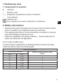
Operating instructions
Programming and display unit
UK
704795 / 00 05 / 2010
PP2001
Contents
1 Preliminary note���������������������������������������������������������������������������������������������������3
1.1 Explanation of symbols����������������������������������������������������������������������������������3
2 Safety instructions������������������������������������������������������������������������������������������������3
3 Items supplied������������������������������������������������������������������������������������������������������4
4 Functions and features�����������������������������������������������������������������������������������������4
5 Function����������������������������������������������������������������������������������������������������������������4
6 Installation������������������������������������������������������������������������������������������������������������5
7 Electrical connection��������������������������������������������������������������������������������������������5
7.1 Offline operation���������������������������������������������������������������������������������������������5
7.1 Online operation���������������������������������������������������������������������������������������������6
8 Operating and display elements���������������������������������������������������������������������������7
9 Menu��������������������������������������������������������������������������������������������������������������������8
9.1 Menu structure�����������������������������������������������������������������������������������������������8
10 Operation������������������������������������������������������������������������������������������������������������9
10.1 Connection of a sensor / initialisation�����������������������������������������������������������9
10.2 Setting the sensor parameters�������������������������������������������������������������������10
10.3 Copying the parameter set of a sensor������������������������������������������������������12
10.4 Changing a stored parameter set���������������������������������������������������������������13
10.5 Transferring a parameter set to other sensors�������������������������������������������14
10.6 Remote display / remote evaluation�����������������������������������������������������������15
11 Scale drawing���������������������������������������������������������������������������������������������������16
12 Technical data���������������������������������������������������������������������������������������������������17
2
1 Preliminary note
1.1 Explanation of symbols
►
>
[…]
→
Instruction
Reaction, result
Designation of pushbuttons, buttons or indications
Cross-reference
Important note:
Non-compliance can result in malfunctions or interference.
UK
2 Safety instructions
• Please read the product description prior to set-up of the unit. Ensure that the
product is suitable for your application without any restrictions.
• If the operating instructions or the technical data are not adhered to, personal
injury and/or damage to property can occur.
• Check the compatibility of the product materials (→ Technical data) with the
media to be measured in all applications.
For the scope of validity cULus:
The device shall be supplied from an isolating transformer having a secondary
Listed fuse rated as noted in the following table.
Overcurrent protection
Control-circuit wire size
AWG
(mm2)
26
(0.13)
24
(0.20)
22
(0.32)
20
(0.52)
18
(0.82)
16
(1.3)
Maximum protective device rating
Ampere
1
2
3
5
7
10
3
3 Items supplied
�
�
1: PP2001
2: cable for connection of a sensor to PP2001
The following components are available as accessories (to be ordered separately):
• Connection cable with M12 connector for voltage supply and output signals of
the sensor (→ catalogue or www.ifm.com).
• 24 V power supply (order no. E30080).
4 Functions and features
The unit can be used for diagnosis and parameter setting of pressure sensors.
The sensor must be suitable for communication with PP2001 or PP2000. Check
the indications in the operation instructions of the sensor.
• PP2001 is suitable for mobile use as well as for permanent installation (→ 6
Installation).
• Sensors can be read and parameterised before installation and set-up or during operation.
If you change parameters during operation, the operating principle of the
production plant will be influenced.
►► Ensure that there will be no malfunctions in your plant.
5 Function
The unit fulfils the following functions:
• It supplies the sensor with operating voltage.
• It detects type, measuring range and the current parameter set of the sensor.
• It reads and displays the current measured value of the sensor.
• It transmits the evaluation signals of the sensor.
4
• It permits modification of the current parameters of the sensor.
• The unit has a rewriteable read-only memory. It can store the parameter set of
a sensor and transmit it to other sensors of the same type by means of simple
actions (COPY and SEND).
• A stored parameter set can be changed and stored again as desired.
They provide the unit with the following operating options :
• Remote parameter setting of sensors (→ 10.2).
• Fast programming / series programming (→ 10.3 / 10.5).
• Changing a stored parameter set (→ 10.4).
UK
• Remote display / remote evaluation (→ 10.6).
6 Installation
For stationary operation two types of installation are possible:
Fixing with mounting clamp
�
A: mounting clamp (to be ordered separately as accessories; order no. E10077).
Fixing with mounting bracket
�
�
A: mounting bracket
Diameter of the bore hole: 18.5...20 mm.
►► Loosen the threaded sleeve (B).
►► Insert the unit in the bore hole.
►► Screw the sleeve and tighten firmly.
7 Electrical connection
7.1 Offline operation
Operation outside the production plant
►► Connect 24 V power supply to PP2001 (plug A).
►► Connect the sensor to PP2001 (socket B) via the supplied connection cable.
5
�
�
�
�
������
�
�
�
�
�
�
7.1 Online operation
Operation with installed sensor during operation of the production plant
�
�
�
�
�
���������� ��
���������� ���
���������� ���
����������
��
�
�
�
�
�
►► Disconnect power.
►► Disconnect the connector from the sensor and screw it to PP2001 (plug A).
►► Connect the sensor to PP2001 (socket B) via the supplied connection cable.
►► Switch on the supply voltage.
6
If you change parameters during operation, the operating principle of the
production plant will be influenced.
►► Ensure that there will be no malfunctions in your plant.
8 Operating and display elements
� � � � � � � �
�
����������
���
��
��
UK
1 to 8: indicator LEDs
- LED 2: green = indication of the system pressure in mbar.
- LED 2 + LED 1: green = indication of the system pressure in mWS.
- LED 3: green = indication of the system pressure in bar.
- LED 3 + LED 1: green = indication of the system pressure in mmWS.
- LED 4: green = indication of the system pressure in kPa.
- LED 4 + LED 1: green = indication of the system pressure in inH2O.
- LED 5: green = indication of the system pressure in MPa.
- LED 5 + LED 1: green = indication of the system pressure in mmHg.
- LED 6: green = indication of the pressure system in PSI.
- LED 6 + LED 1: green = indication of the pressure system in inHg.
- LED 7: yellow = output 2 is switched.
- LED 8: yellow = output 1 is switched.
9: Alphanumeric display, 4 digits
- System pressure is displayed.
- Parameters, parameter values and action points are displayed.
10: Set button
- Setting of the parameter values (continuously by keeping the button pressed; incrementally by pressing once).
- Triggering a COPY or SEND action.
11: Mode/Enter button
- Selection of the parameters and acknowledgement of the parameter values.
7
9 Menu
9.1 Menu structure
���
�
�
�
�
�
�
�
�
�
�
�
�
�
�
�
�
�
�
�
�
�
�
�
�
�
�
�
1: sensor-specific parameters (depending on the connected sensor)
2: action points of the PP2001
8
10 Operation
10.1 Connection of a sensor / initialisation
1
►► Connect the sensor to PP2001.
►► Apply operating voltage.
>> Initial display is shown.
UK
Sensor type (running display)
2
>> The current measured value is
displayed.
PP2001 and sensor are operational.
Notes:
• If only [COPY] and [SEND] are active in the operating mode, the connected
sensor does not support the parameter setting and editing functions.
Only the evaluating function (Transmission of the output signals, → 10.6) and
the copy functions (→ 10.3 and 10.5) are supported.
• If the sensor is disconnected, a running display indicates the type of the stored
data set. Then [EDIT] is displayed.
• If another sensor is connected, the initialisation (step 1) starts again.
Error messages
[E.COM]
[E.INI]
Input output error: communication error / data transfer disturbed.
Communication error or data error; initialisation / support of the sensor not
possible.
9
10.2 Setting the sensor parameters
During parameter setting the unit remains in the operating mode. It continues its
monitoring function with the existing parameters until the parameter setting has
been completed.
The following steps must be taken for each parameter setting:
1
2
3
►► Connect the sensor to PP2001.
>> The unit passes the initialisation
phase and then displays the current
measured value.
Selection of the parameter
►► Press [Mode/Enter] until the requested parameter is displayed.
���������� ���
Setting of the parameter value
►► Press [Set] and keep it pressed.
>> Current setting value of the param���������� ���
eter flashes for 5 s.
>> After 5 s: setting value is changed:
incrementally by pressing the button
once or continuously by keeping the
button pressed.
Numerical values are incremented continuously. For reducing the value: let the display move to the maximum setting value. Then the cycle starts again at the minimum
setting value.
4 Acknowledgement of the parameter
value
���������� ���
►► Press [Mode/Enter] briefly.
>> [SEND] is briefly displayed, then the
parameter designation.
>> The new setting value is stored in the
sensor and now effective.
Setting of other parameters:
►► Start again with step 1.
Finishing the parameter setting:
►► Press [Mode/Enter] several times until the current measured value is displayed or wait
for 15 s. The unit returns to the operating mode if no button is pressed for 15 s after
acknowledgement of the new parameter value.
Finishing the parameter setting and storing the changed parameter set in PP2001:
►► Carry out the [COPY] action (→ 10.3)
10
• With this parameter setting only the parameter set of the sensor is
changed. The parameter set stored in PP2001 remains unchanged.
• Do not activate the action point [SEND]. This would cause the parameter set stored in PP2001 to be transferred to the sensor.
• If [SLoc] is displayed when attempting a modification of a parameter
value, the sensor is locked via FDT software. This locking can only be
removed via FDT software.
• Change from menu level 1 to menu level 2:
►► Press [Mode/Enter] until [EF] is
displayed.
►► Press [Set] briefly.
>> The first parameter of the sub-menu
is displayed (here: [HI]).
UK
���������� ���
���������� ���
• Locking / unlocking
The sensor can be locked electronically to prevent unintentional settings.
►► Make sure that the unit is in the
normal operating mode.
►► Press [Mode/Enter] + [Set] for 10 s.
>> [Loc] is displayed.
���������� ���
����
During operation: > [Loc] is briefly displayed if you try to change parameter values.
For unlocking:
►► Press [Mode/Enter] + [Set] for 10 s.
���������� ���
>> [uLoc] is displayed.
����
On delivery: unlocked.
• Timeout:
If no button is pressed for 15 s during parameter setting, the unit returns to the operating mode with unchanged values.
11
10.3 Copying the parameter set of a sensor
1
2
3
4
►► Connect the sensor to PP2001.
>> The unit passes the initialisation
phase (→ 10.1) and then displays the
current measured value.
►► Press [Mode/Enter] until [COPY] is
displayed.
���������� ���
►► Press [Set] and keep it pressed.
>> [WAIT] flashes.
���������� ���
►► Release [SET].
>> [DONE] is briefly displayed. The
copying process is finished and the
parameter set of the sensor is stored
in PP2001.
►► Press [Mode/Enter] briefly.
>> The unit goes into the operation mode (the sensor type and then the current
measured value are displayed).
Error messages when carrying out the COPY action:
[E.COM]
[E.INI]
Input output error: communication error / data transfer disturbed.
Communication error or data error; initialisation / support of the sensor not
possible.
[E.SEN] Sensor type error: the sensor type is not supported.
[E.STO] Error when storing the data set (e.g. B: data set too large).
The error message is displayed for 5 s. Then the menu [COPY] is again active.
In case of communication via IO-Link with a low baud rate the operation can take one minute
or more.
12
10.4 Changing a stored parameter set
1
►► Apply operating voltage.
>> Initial display is shown.
Sensor type (running display)
2
3
4
►► As soon as the running display appears: press [Mode/Enter] briefly.
>> [EDIT] is displayed.
►► Press [Set] for 5 s.
>> The first menu item is displayed
(here [SP1]).
UK
���������� ���
���������� ���
>> Carry out the parameter setting (→ 10.2).
This operation can only be carried out if no sensor is connected.
If for the data set stored in PP2001 only the copy functions are supported,
the editing function is not active. After step 2 ([Mode/Enter] pressed
briefly), [TYPE] and the sensor type are displayed (running display).
Timeout:
If no button is pressed for 15 s, the unit returns to step 2. A parameter change
which has not been acknowledged is not adopted.
13
10.5 Transferring a parameter set to other sensors
1
2
►► Press [Mode/Enter] until [SEND] is
displayed.
►► Press [Set] and keep it pressed.
>> [WAIT] flashes.
►► Release [SET].
>> [DONE] is briefly displayed, then
again [SEND].
The copying process is finished and the
parameter set of PP2001 is stored in
the sensor.
���������� ���
���������� ���
Transferring a parameter set to other sensors
►► Remove the sensor from the connection cable.
>> [- - - -] is displayed until a new sensor is connected.
►► Connect the new sensor.
>> [READ] is briefly displayed, then [SEND].
►► Carry out step 2.
The processes can be carried out as often as desired.
Finishing the copying process:
►► Press [Mode/Enter] when [SEND] is displayed.
>> The unit goes into the operation mode (the sensor type and then the current measured
value are displayed).
In case of communication via IO-Link with a low baud rate the operation can take one minute
or more.
Error messages when carrying out the SEND action:
[E.COM]
[E.INI]
Input output error: communication error / data transfer disturbed.
Communication error or data error; initialisation / support of the sensor not
possible.
[E.SEN] Sensor type error: the parameter set does not correspond to the type / measuring range of the sensor.
[E.DAT] Data error: at least one parameter of the internal data set is not within the valid
range of the connected sensor.
The error message is displayed for 5 s. Then the menu [COPY] is again active.
14
10.6 Remote display / remote evaluation
After connection of a sensor and initialisation (→ 10.1) the current measured value
is diplayed. The output signals of the sensor are transmitted and provided at the
output of the PP2001.
Reading of the set parameters
►► Press [Mode/Enter] briefly: the parameters are displayed one after the other.
►► Press [Set] briefly: the corresponding parameter value is displayed for about 15
s. After another 15 s the unit returns to the Run mode.
Error messages
UK
[SC1]
Short circuit in OUT1 of PP2001.*
[SC2]
Short circuit in OUT2 of the connected sensor (signalled via the communication
interface to PP2001).*
[SC]
Short circuit in both outputs.*
*The output concerned is switched off as long as the short circuit exists.
These messages are displayed even if the display is switched off.
15
11 Scale drawing
�
�
��
��
��� ��
�
��
��
���
�
��
Dimensions in mm
1: 4-digit alphanumeric display
2: LEDs (display unit / switching status)
3: programming button
4: connection for voltage supply and output signals
5: connection for sensor
6: nut
16
��
�
�� �
12 Technical data
Operating voltage [V].......................................................................................... 18 ... 32 DC
Current rating [mA]...........................................................................................................250
Short-circuit protection (pulsed); protected against reverse polarity and overload
Voltage drop [V].................................................................................................................< 2
Current consumption [mA]...............................................................................................< 40
Power-on delay time [s]..........................................................................................1.5...10 *)
Response time for transferring
the sensor output signal [ms].................................................................OU1 < 50 / OU2 = 0
Measurement / display cycle time [ms]............................................................................200
Housing materials...........................................stainless steel 316L / 1.4404; PC Copolymer;
PBT (Pocan); FPM (Viton)
Protection...................................................................................................................... IP 67
Protection class...................................................................................................................III
Insulation resistance [MΩ]]........................................................................> 100 (500 V DC)
Shock resistance [g].............................................................. DIN IEC 68-2-27: 50 g (11 ms)
Vibration resistance [g]................................................. DIN IEC 68-2-6: 20 g (10...2000 Hz)
Operating temperature [°C]..................................................................................... -25 ... 80
Storage temperature [°C]...................................................................................... -40 ... 100
EMC
EN 61000-4-2 ESD: .......................................... 4 kV contact discharge / 8 kV air discharge
EN 61000-4-3 HF radiated: ....................................................................................... 10 V/m
EN 61000-4-4 Burst: ...................................................................................................... 2 kV
EN 61000-4-6 HF conducted: ........................................................................................ 10 V
*) depending on the connected sensor
More information at www.ifm.com
17
UK