1
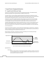
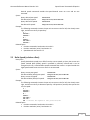
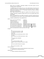
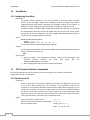
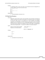
COMPUTER CONTROLLED PAN‐TILT UNIT VERSION: 3.02 REVISION DATE: SEPTEMBER 6, 2011 COMMAND REFERENCE MANUAL 890C Cowan Road, Burlingame, CA 94010 • (650) 692‐3900 • FAX: (650) 692‐3930 [email protected] • www.FLIR.com/mcs Pan‐Tilt Unit Command Reference Manual, August 3, 2011 ©1991, 2011 by FLIR Motion Control Systems, Inc., 890C Cowan Road, Burlingame, California 94010, (650)692‐3900, FAX: (650)692‐3930, www.FLIR.com/mcs. All rights reserved. Protected under numerous U.S. Patents including 5463432 and 5802412, and patents pending. No part of this book may be reproduced, stored in a retrieval system, or transcribed, in any form or by any means, electronic, mechanical, photocopying, recording, or otherwise, without the prior written permission of FLIR Motion Control Systems, Inc. The information in this manual is subject to change without notice and, except for the warranty, does not represent a commitment on the part of FLIR Motion Control Systems. FLIR Motion Control Systems cannot be held liable for any mistakes in this manual and reserves the right to make changes. Table of Contents 1. Overview ............................................................................................................................................... 6 2. Binary Command Format ...................................................................................................................... 6 3. General ASCII Command Format .......................................................................................................... 6 4. Positional Control Commands & Queries ............................................................................................. 6 5. 6. 4.1 Position (absolute) ........................................................................................................................ 6 4.2 Offset Position (relative offset) ..................................................................................................... 7 4.3 Resolution per Position ................................................................................................................. 7 4.4 Limit Position Queries ................................................................................................................... 8 4.5 Position Limit Enforcement ........................................................................................................... 8 4.6 Immediate Position Execution Mode ............................................................................................ 9 4.7 Slaved Position Execution Mode ................................................................................................... 9 4.8 Await Position Command Completion .......................................................................................... 9 4.9 Halt Command ............................................................................................................................ 10 4.10 Monitor (Autoscan) Command ................................................................................................... 10 4.11 Position Presets ........................................................................................................................... 11 Speed Control Commands & Queries ................................................................................................. 12 5.1 Speed Control & Relevant Terms ................................................................................................ 12 5.2 Delta Speed (relative offset) ....................................................................................................... 13 5.3 Acceleration ................................................................................................................................ 14 5.4 Base (Start‐Up) Speed ................................................................................................................. 14 5.5 Speed Bounds ............................................................................................................................. 15 5.6 Speed Control Modes.................................................................................................................. 15 Continuous Axis Rotation .................................................................................................................... 16 6.1 7. 8. Enabling/Disabling Continuous Rotation .................................................................................... 16 User Defined Pan‐Tilt Limits ................................................................................................................ 17 7.1 Limit Position Queries ................................................................................................................. 18 7.2 Position Limit Enforcement ......................................................................................................... 18 Unit Commands .................................................................................................................................. 20 8.1 Reset Pan‐Tilt Unit ...................................................................................................................... 20 8.2 Default Save/Restore .................................................................................................................. 20 8.3 Echo Query/Enable/Disable ........................................................................................................ 21 8.4 Feedback Verbose/Terse/Off ...................................................................................................... 21 8.5 Controller Firmware Version Query ............................................................................................ 21 8.6 Outside Supply Voltage and Controller Temperature Query ...................................................... 22 9. Power Control Commands & Queries ................................................................................................. 22 9.1 Stationary Power Mode .............................................................................................................. 22 9.2 In‐Motion Power Mode .............................................................................................................. 23 10. 10.1 11. 11.2 Configuring Expanded Serial Port Communications ................................................................... 26 11.3 Attaching a Mouse/Trackball to an Expanded Serial Port .......................................................... 26 11.4 Expansion Analog Joystick Commands ....................................................................................... 27 13. EIO Option: Expansion Serial Ports and Control ............................................................................. 24 Select Serial Communications Target ......................................................................................... 25 12.1 Configuring Host Serial Port Baud and Communications ........................................................... 23 11.1 12. Host Serial Port and Control ........................................................................................................... 23 Step Modes ..................................................................................................................................... 28 Configuring Step Mode ............................................................................................................... 28 PTU Network Software Commands ................................................................................................ 28 13.1 Unit Network ID .......................................................................................................................... 28 13.2 Unit Select/Deselect .................................................................................................................... 29 Table of Figures Figure 1 Axis Speed during On‐The‐Fly Desired Speed and Position Changes ........................................... 12 Figure 2 User Limit Ranges .......................................................................................................................... 18 Overview Command Reference Manual Version 3.02 1. Overview This document describes the pan‐tilt unit command set. Each command has a section that provides a brief functional description, a format (syntax) description, examples, and related topics. When controlling the pan‐tilt unit from a terminal, a complete menu of pan‐tilt commands can be obtained by entering the character “?”. All FLIR Motion Control Systems Products support this command set, and where commands vary between products, look at the description for the command to determine if it is supported. 2. Binary Command Format A C Programmer’s Interface (model PTU‐CPI) is available for higher bandwidth binary communications between a host computer and the PTU controller. 3. General ASCII Command Format When describing the format (syntax) of pan‐tilt commands, the following conventions are adopted: • • • • Commands issued to the pan‐tilt unit (e.g., typed in by you) are shown in bold. Input characters may be in upper or lower case (we show them in upper case for presentational consistency) A delimiter (<delim>) can be either a space (“ ”) or a carriage return (<CR>). A successfully executed command returns “*<CR>”. Successful query execution returns “* <QueryResult><CR>”. Command execution failure returns “! <ErrorMessage><CR>”. A pan axis limit hit asynchronously returns “!P” and a tilt axis limit hit asynchronously returns “!T”. 4. Positional Control Commands & Queries 4.1 Position (absolute) Description Specify or query the absolute pan or tilt axis position. Desired positions can be changed on‐the‐fly without waiting for previous position commands to complete. Syntax Query current absolute pan position: PP<delim> Set desired absolute pan position: PP<position><delim> Query current absolute tilt position: TP<delim> Set desired absolute tilt position: TP<position><delim> Example The following sends the pan axis to the left, waits, then sends it to the right: PP-2500 * A * PP * Current Pan position is -2500 6 Command Reference Manual Version 3.02 Positional Control Commands & Queries PP2500 * A * PP * Current Pan position is 2500 Related Topics Position (relative offset and desired position queries): See Section 4.2 Position resolution (units): See Section 4.3 Position limits: See Section 4.4 Position execution modes: See Sections 4.6, 4.7 and 4.8 Position limit enforcement modes: See Section 4.5 4.2 Offset Position (relative offset) Description Specify desired axis position as an offset from the current position, or Query the current axis position. Desired offset positions can be changed on‐the‐fly without waiting for previous position commands to complete. Syntax Query desired pan position: PO<delim> Set desired offset pan position: PO<position><delim> Query desired tilt position: TO<delim> Set desired offset tilt position: TO<position><delim> Example The following sends the pan axis to position ‐500, then sends it 1500 positions to the left: PP-500 * A * PO * Current Pan position is -500 PO1500 * A * PP * Current Pan position is 1000 Related Topics Position resolution (units): See Section 4.3 Position limits: See Section 4.4 Position execution modes: See Sections 4.6, 4.7 and 4.8 Position limit enforcement modes: See Section 4.5 4.3 Resolution per Position Description Query returns the axis resolution per position moved (in seconds/arc). Syntax Query pan resolution: PR<delim> Query tilt resolution: TR<delim> Example Resolution can be determined by: PR * 92.5714 seconds arc per position 1 sec arc = 1°/3600 = 0.0002778° 7 Positional Control Commands & Queries Command Reference Manual Version 3.02 So one position (92.5714 seconds arc) is 92.5714 sec arc * 0.0002778° = 0.02572°. Thus, to pan 21.3° left requires a relative move of 21.3°/0.02572 ≈ 828 positions, yielding the following command: PO828 * Related Topics Step Modes: See Section 12 4.4 Limit Position Queries Description Queries return the axis position bounds determined upon unit reset. Syntax Query minimum pan position: PN<delim> Query maximum pan position: PX<delim> Query minimum tilt position: TN<delim> Query maximum tilt position: TX<delim> Example R * PN * Minimum Pan position is -3090 PX * Maximum Pan position is 3090 TN * Minimum Tilt position is -907 TX * Maximum Tilt position is 604 LE * PP3200 ! Maximum allowable Pan position is 3090 Related Topics Position resolution (units): See Section 4.3 Achieving larger axis bounds: See Section 7.2 4.5 Position Limit Enforcement Description Determines whether position commands beyond the detected pan axis limits are allowable. The default is pan position limits are enabled (i.e., enforced). When limits are enabled, commands outside of the limits return an error message and are not executed. In enabled limit mode, limits are only reached when the unit has lost synchrony and this error condition requires a unit reset (see Section 4.5.1). When a limit is reached, a “!P” is printed to the host serial port to indicate that the pan axis limit was hit. When larger operational pan ranges are required, the limits may be disabled. Positional pan commands outside the limits are not rejected when limits are disabled. Syntax Query current pan position limit mode: L<delim> Enable pan position limits: LE<delim> Disable pan position limits: LD<delim> Example L * Limit bounds are ENABLED (soft limits enabled) PX * Maximum Pan position is 3090 PP3200 ! Maximum allowable Pan position is 3090 LD * 8 Command Reference Manual Version 3.02 Positional Control Commands & Queries PP3200 * A * PP * Current Pan position is 3200 Related Topics Position commands: See Sections 4.1 and 4.2 4.6 Immediate Position Execution Mode Description Instructs pan‐tilt unit to immediately execute positional commands. This is the default mode. Syntax I<delim> Example For the below commands, the pan axis will immediately execute the pan position command: I * PP1000 * Related Topics Alternative slaved position execution mode: See Section 4.7 4.7 Slaved Position Execution Mode Description Instructs pan‐tilt unit to execute positional commands only when an Await Position Command Completion command is executed (see Section 4.8) or when put into Immediate Execution Mode (see Section 4.6). This mode is useful when coordinated pan and tilt axis movements are desired. Syntax S<delim> Example The following commands change the position execution mode, instruct the axes which position to achieve, and an await command causes the position commands to be executed simultaneously: DR * S * PP1500 * TP-900 * PP * Current TP * Current A * PP * Current TP * Current Pan position is 0 Tilt position is 0 Pan position is 1500 Tilt position is -900 Related Topics Alternative immediate position execution mode: See Section 4.6 4.8 Await Position Command Completion Description Awaits the completion of the last issued pan and tilt axis position commands. Used to coordinate axis motions. Syntax 9 Positional Control Commands & Queries Command Reference Manual Version 3.02 A<delim> Example The following commands instruct the pan axis to move to a position, then move to another position: I * PP * Current Pan position is 0 PP2000 * A * PP * Current Pan position is 2000 PP0 * A * PP * Current Pan position is 0 In contrast, the following commands would begin to move to the first position, and before that position is reached, the next position would be moved towards (this is often called an on‐the‐fly position change): I * PP * Current Pan position is 0 PP2000 * PP0 * Related Topics This command can be used for both the Immediate Position Execution Mode (see Section 4.6) and Slaved Position Execution Mode (see Section 4.7) 4.9 Halt Command Description Immediately decelerates and halts pan‐tilt movement. Syntax H<delim> Halt all pan‐tilt movement: Halt pan axis movement: HP<delim> Halt tilt axis movement: HT<delim> Example PP2500 * A * PP-2500 Then while the pan‐tilt is moving, the host decides to stop immediately: H * Related Topics This command can be used for both the Immediate Position Execution Mode (see Section 4.6) and Slaved Position Execution Mode (see Section 4.7) 4.10 Monitor (Autoscan) Command Description Command defines and initiates repetitive monitoring (scanning) of the pan‐tilt. Autoscanning is immediately terminated upon receipt of a character from the host computer, and the pan‐tilt is sent to its home position. Syntax Initiate monitor (autoscan) in pan axis only: M<pan pos 1>,<pan pos 2><delim> Initiate monitor (autoscan) in both pan and tilt axes: 10 Command Reference Manual Version 3.02 Positional Control Commands & Queries M<pan pos 1>,<pan pos 2>,<tilt pos 1>,<tilt pos 2><delim> Initiate last defined monitor (autoscan) command (the default at power up is pan axis only autoscan between the pan limit positions): M<delim> Enable monitor (autoscan) at power up: ME<delim> Disable monitor (autoscan) at power up: MD<delim> MQ<delim> Query monitor status at power up: Example When executed at power up, M * the pan‐tilt begins scanning between the minimum and maximum pan limit positions. <delim> terminates the scanning and homes the pan‐tilt. Other monitoring command forms: M-2500,100 * M-2500,100,-800,600 * M0,0,-300,300 * Related Topics Limit Position Queries (see Section 4.4) 4.11 Position Presets Description Position preset functionality is provided for backward compatibility with legacy CCTV applications. D300 pan‐tilt controller firmware version v2‐12‐11r2 and higher support position presets. The pan‐tilt can be commanded to a position using any of the standard motion control commands of the D300 PTU. The current pan and tilt position can be stored as a numbered “preset”. The PTU can then be commanded to a previously stored preset using a new “go to preset” command. Currently set motion parameters (acceleration, base rate, etc.) apply during “go to preset” commands. Preset positions are remembered when the controller is repowered. Syntax XS<index><delim> where <index> ? [0..32] “Set Preset” XG<index><delim> where <index> ? [0..32] “Goto Preset” XC<index><delim> where <index> ? [0..32] “Clear Preset” Example The following commands set the Pan/Tilt to position 500/400, store as preset 0, move the unit to position 600/800, and then goes back to previously stored preset 0 position. PP500 TP400 XS0 * PP600 TP800 XG0 * * * * 11 Speed Control Commands & Queries Command Reference Manual Version 3.02 5. Speed Control Commands & Queries 5.1 Speed Control & Relevant Terms The Pan‐Tilt Unit provides for precise control of axis speed and acceleration. This subsection briefly describes how speed control is performed and it introduces relevant terms. As shown in Figure 1, upper and lower speed limits determine the bounds on nonstationary pan‐tilt velocities. The base (start‐up) speed specifies the velocity at which the pan‐tilt axis can be started from a full stop without losing synchrony and it is more a function of the motors rather than load characteristics. Due to base speed requirements and the property that motors lose torque as speed increases, acceleration is required to achieve axis speeds above the base rate. The pan‐tilt controller uses trapezoidal acceleration and deceleration for speeds above the base rate and less than the maximum allowed speed. Figure 5 shows two acceleration cases. In the first, an axis accelerates up to a desired constant speed (slew rate), then decelerates. The second case shows the case when the unit does not have sufficient time to accelerate up to the desired slew speed before the need to decelerate to the desired position. The pan‐tilt controller provides for on‐the‐fly position and speed changes. If the direction is changed on‐ the‐fly, the controller manages all deceleration, direction reversal, and acceleration to achieve the most recently specified target pan‐tilt speed and acceleration rates. Because speed, acceleration, and position are precisely controlled, you can accurately and simply predict the position attained by the pan‐tilt unit in time. Upper Speed Limit Speeds Requiring Acceleration Base Speed Instantaneous Speed Changes Lower Speed Limit Time Figure 1 Axis Speed during On‐The‐Fly Desired Speed and Position Changes Speed (absolute) Description Specify or query desired axis speed. Desired speed is specified in positions/ second and it can be changed on‐the‐fly. The speed specifies the rate at which the pan‐tilt moves to achieve position movement commands. 12 Command Reference Manual Version 3.02 Speed Control Commands & Queries Desired speed commands outside the speed bounds return an error and are not executed. Syntax Query desired pan speed: PS<delim> Set desired pan speed: PS<positions/sec><delim> Query desired tilt speed: TS<delim> Set desired tilt speed: TS<positions/sec><delim> Example The following commands instruct the pan axis to move to the far left, then slowly move right, and then on‐the‐fly it speeds up: I * PS1900 * PP2600 * A * PS600 * PP-2600 * PS1900 * Related Topics Position commands: See Sections 4.1 and 4.2 Position resolution (units): See Section 4.3 Speed bounds: See Section 5.5 5.2 Delta Speed (relative offset) Description Specify desired axis speed as an offset from the current speed, or Query the current axis speed. Desired delta (offset) speed is specified in positions/ second and it can be changed on‐the‐fly. A desired delta speed command that results in a speed outside the legal speed bounds returns an error and it is not executed. Syntax Query current pan speed: PD<delim> Set desired delta (offset) pan speed: PD<positions/sec><delim> Query current tilt speed: TD<delim> Set desired delta (offset) tilt speed: TD<positions/sec><delim> Example The following commands instruct the pan axis to move to the far left, then slowly move right, and then on‐the‐fly it decreases speed by ‐150 positions/ second, then queries the current speed: I * PS1900 * PP2600 * A * PS600 * PP-2600 * PD-150 * PD * Current Pan speed is 450 positions/sec Related Topics Position commands: See Sections 4.1 and 4.2 Position resolution (units): See Section 4.3 13 Speed Control Commands & Queries Command Reference Manual Version 3.02 Speed bounds: See Section 5.5 5.3 Acceleration Description Specify or query axis acceleration and deceleration for speeds above the base speed. Acceleration is specified in positions/second2. Syntax Query desired pan acceleration: PA<delim> Set desired pan acceleration: PA<positions/sec2><delim> Query desired tilt acceleration: TA<delim> Set desired tilt acceleration: TA<positions/sec2><delim> Example The following illustrate different rates of acceleration: PA * Pan acceleration is 2000 positions/sec^2 PB * Current Pan base speed is 1000 positions/sec PU * Maximum Pan speed is 2902 positions/sec PP0 * PS1900 * PP2600 * PA1500 * PP0 * Related Topics Position resolution (units): See Section 4.3 Symmetric trapezoidal acceleration is used, so the rate of deceleration is equivalent to the rate of acceleration Acceleration cannot be changed on‐the‐fly since it takes several seconds to re‐ compute the internal tables used to rapidly execute speed ramping. 5.4 Base (Start‐Up) Speed Description Specify or query axis base (start‐up) speed. Base speed is specified in positions/second. Defaults to 57 positions/sec. Syntax Query desired pan base speed: PB<delim> Set desired pan base speed: PB<positions/sec><delim> Query desired tilt base speed: TB<delim> Set desired tilt base speed: TB<positions/sec><delim> Example The following commands home the pan axis, moves it far left, changes the base rate, then moves back to home: I * PP0 * A * PP2600 * PB * Current Pan base speed is 1000 positions/sec PB1000 * PP0 * Related Topics Position resolution (units): See Section 4.3 14 Command Reference Manual Version 3.02 Speed Control Commands & Queries Acceleration: See Sections 5.1 and 5.3 Speed bounds: See Section 5.5 Changes in the base rate cannot be made on‐the‐fly since it takes several seconds to re‐compute the internal tables used to rapidly execute speed ramping. 5.5 Speed Bounds Description Set and query the upper and lower speed bounds for desired speed commands. Syntax Query upper pan speed limit: PU<delim> Set upper pan speed limit: PU<positions/sec><delim> Query lower pan speed limit: PL<delim> Set lower pan speed limit: PL<positions/sec><delim> Query upper tilt speed limit: TU<delim> Set upper tilt speed limit: TU<positions/sec><delim> Query lower tilt speed limit: TL<delim> Set lower tilt speed limit: TL<positions/sec><delim> Example PU * Maximum PS3300 ! Pan PS1985 * PL * Minimum PL20 ! Motor PL40 * Pan speed is 1985 positions/sec speed cannot exceed 1985 positions/sec Pan speed is 31 positions/sec speed cannot be less than 31 pos/sec Related Topics Position resolution (units): See Section 4.3 Changes in the upper speed limit cannot be made on‐the‐fly since it takes several seconds to re‐compute the internal tables used to rapidly execute speed ramping. 5.6 Speed Control Modes Description By default, position control commands are independent from the speed control commands. In this independent control mode, the commanded speed is an unsigned magnitude that determines the speed at which independently commanded positions are effected, and the execution of these speed commands do not affect the commanded desired positions themselves. This mode is appropriate for pure position control methods (when pan‐tilt control is affected solely by commanding pan‐tilt position) and hybrid position‐velocity control methods (when pan‐tilt positions and the rate at which they are achieved are both controlled). An alternative pan‐tilt control method uses a pure velocity control mode in which all pan‐tilt control is affected by signed changes in command axis speed. In this mode, the speed command specifies a signed velocity in which the sign determines the direction of axis movement, and the ordinal value specifies the speed of movement in this direction. In this mode, if the commanded speed is negative, the axis is automatically commanded to the minimum axis position. Conversely, if the speed command is positive, the axis is automatically commanded to the maximum axis position. A speed of zero is applied by halting the axis motion. It is important to note that in pure velocity control mode, a speed command for a given axis effectively 15 Continuous Axis Rotation Command Reference Manual Version 3.02 overrides currently executing position commands. As a result, the speed control mode at power up is always set to independent control mode; the speed control mode is not saved as defaults that are preserved when the unit is powered back up. These commands are available in PTU firmware versions 1.09.7 and higher. Syntax Query the current speed control mode: C<delim> Set to independent control mode (default): CI<delim> Set to pure velocity control mode: CV<delim> Example Put into the default independent control mode, the pan‐tilt will finish at position ‐3000. Put in the pure velocity control mode, the pan‐tilt will finish on the opposite pan side. Note that the default restore (also executed upon unit power up) restores the unit to independent control mode: CI * PP-3000 * PS1000 * A * CV * PP-3000 * PS1000 * DR * PP-3000 * PS1000 * Related Topics Position commands: See Sections 4.1 and 4.2 Speed commands: See Section 0 and 5.2 6. Continuous Axis Rotation D300 and D100 pan‐tilt controller firmware versions v2.12.12r7 and higher provide for continuous rotation in position and pure velocity modes. This section describes the command syntax and semantics that support continuous axis rotation. 6.1 Enabling/Disabling Continuous Rotation Description: To allow the unit to perform continuous pan axis rotation using the integral slip ring, you must issue the command “%%1CPT LD “. To make this the default at power up, you must then issue the command “DS “. An axis Reset is required before the minimum (N) and maximum (X) allowed positions are set (e.g., viewed via the “PN PX “ pan‐tilt commands). Standard DP pan‐tilt axis coordinates designate home as position 0 with movement in either direction determined by the sign bit of the position. (The User’s Manual details the coordinate system and controls.) All position commands should be in the range [N..X] inclusive. For a given current position, the axis will be moved in the direction closest to the desired position. Syntax: %%1C<axis><enable continuous axis><delim> where <axis> :== T | P 16 Command Reference Manual Version 3.02 User Defined Pan‐Tilt Limits <enable continuous axis> :== T | F for True or False After the above is selected, an axis reset is required for the proper minimum and maximum position boundaries to be set. Example: For a PTU‐D46‐17 with a pan axis whose hardware provides for continuous rotation, using a quarter microstep, and saving this as the power up default: %%1CPT * LD * DS * RP * PN * Minimum Pan position is –6999 PX * Maximum Pan position is 7000 PP7000 * A * PP‐6900 * A * CV * PS1000 * Known Limitations: The following issues are known and will be addressed in future firmware: PO/TO fail across the N/X discontinuity. Slow accelerations may overshoot for moves close to the N/X boundary. Final position will be accurate. 7. User Defined Pan‐Tilt Limits FLIR Motion Control Systems pan‐tilt controllers (firmware versions v2.13.1r0 and higher) allow user defined limits on commanded positions. The pan‐tilt must perform a power up calibration to its factory limits to establish its axis coordinates, and then the user defined limits ensure that all subsequent movement commands for that axis will be kept in the allowed range of motion. Movements commanded outside the user defined limits (when activated) will return a status indicating the error. FLIR Motion Control Systems pan‐tilt units employ an internal factory‐installed vane to precisely calibrate each axis. As depicted in the figure below, the factory‐installed limits define the possible range of motion allowed for that axis when limits are enabled, and movement of an axis outside its factory limits is prevented with an electronic lockout feature. (Pan‐tilts which include an internal slip ring allow continuous pan rotations with limit enforcement disabled.) User defined limits are a subset of the factory limits. They are defined by commands issued to the pan‐tilt, and the user defined limits can be stored and restored automatically at power up. 17 User Defined Pan‐Tilt Limits Command Reference Manual Version 3.02 Factory Limits: User Defined Limits: HOME Figure 2 User Limit Ranges 7.1 Limit Position Queries Description: Queries return the axis position bounds determined upon unit reset (factory limits) and user defined limits (within the factory limits). Syntax: Query minimum pan factory limit position: PN<delim> Query maximum pan factory limit position: PX<delim> Query minimum tilt factory limit position: TN<delim> Query maximum tilt factory limit position: TX<delim> Query minimum pan user defined limit position: PNU<delim> Query maximum pan user defined limit position: PXU<delim> Query minimum tilt user defined limit position: TNU<delim> Query maximum tilt user defined limit position: TXU<delim> Example: R * PN * Minimum Pan position is ‐3090 PX * Maximum Pan position is 3090 TN * Minimum Tilt position is ‐907 TX * Maximum Tilt position is 604 LE * PP3200 ! Maximum allowable Pan position is 3090 PNS * Minimum Pan user defined position is ‐1000 Known Limitations: The following issues are known and will be addressed in future firmware: PO/TO fail across the N/X discontinuity. Related Topics Position resolution (units): See Section 4.3 Achieving larger axis bounds: See Section 7.2 7.2 Position Limit Enforcement Description: Determines whether position commands beyond the factory limits or user defined limits are allowable. Factory limits are enabled by default (i.e., enforced). 18 Command Reference Manual Version 3.02 User Defined Pan‐Tilt Limits When limits are enabled, commands outside of the limits return an error message and are not executed. In enabled factory limit mode, limits are only reached when the unit has lost synchrony and this error condition requires a unit reset (see Section 4.5). When a factory limit is reached, a “!P” or “!T” is printed to the host serial port to indicate that an pan axis limit was hit. When larger operational pan ranges are required, limit enforcement may be disabled. Positional commands outside the limits are not rejected when limits are disabled. When user defined limits are enabled, commands to positions outside the limits are rejected with an error status. In pure velocity mode, the maximum positions attained are defined by the user defined limits. Syntax: L<delim> Query current limit enforcement: Enable factory limits: LE<delim> Enable user defined limits: LU<delim> Disable limit enforcement: LD<delim> Set minimum pan user defined limit: PN<panpos><delim> Î <status> Set maximum pan user defined limit: PX<panpos><delim> Î <status> Set minimum tilt user defined limit: TN<tiltpos><delim> Î <status> Set maximum tilt user defined limit: TX<tiltpos><delim> Î <status> where user defined limits are within the factory limit range. Example: R * PN * Minimum Pan position is ‐3090 PX * Maximum Pan position is 3090 PNU‐1000 * PNU * Minimum user defined Pan Position is ‐1000 PXU1500 * PXU * Maximum user defined Pan Position is 1500 LE * L * Limit bounds are ENABLED PP‐3000 * A * PP * Current Pan position is ‐3000 PP3200 ! Maximum allowable Pan position is 3090 LU * L * Limit user defined bounds are enabled A * PP * Current Pan position is ‐1000 Known Limitations: The following issues are known and will be addressed in future firmware: PO/TO fail across the N/X discontinuity. Related Topics: Position commands: See Sections 4.4 and 4.5. 19 Unit Commands Command Reference Manual Version 3.02 8. Unit Commands 8.1 Reset Pan‐Tilt Unit Description This command controls how, and when, the pan‐tilt unit is calibrated. By default, the pan‐tilt unit is configured to reset both the pan and tilt axes automatically upon power up and by issuing the reset command. The reset mode commands are used to control the reset performed at pan‐tilt power up, and to allow reset of an individual pan‐tilt axis. The reset calibration allows the pan‐tilt unit to determine axis coordinates, hence a pan‐tilt axis should be reset prior to issuing any axis position commands. A pan‐tilt axis that has not been calibrated has a minimum and maximum axis position of 0 (see Section 4.4), hence position commands in limit enabled mode (see Section 4.5) will return an illegal position command feedback. Syntax Performs Reset calibration: R<delim> Reset modes (saved in internal EEPROM for power up reset control): RD<delim> Disable reset upon power up: Reset tilt axis only: RT<delim> Reset pan axis only: RP<delim> Reset both pan and tilt axes upon power up: RE<delim> Example RT * R * RP * R * RD * R * RE * R * Related Topics A load beyond the handling capacity of the pan‐tilt unit may cause the reset to fail, so load handling capability should be tested as described in the pan‐tilt user manual. 8.2 Default Save/Restore Description Allows current axis settings to be saved as defaults that are preserved when the unit is powered back up. Also allows the factory defaults to be restored. The following changeable settings are saved/restored: • Serial port settings (host, CHA/B) • Maximum speed • Desired speed • Base speed • Acceleration • Hold and move power • Monitor positions • Continuous rotation mode 20 Command Reference Manual Version 3.02 • • • Unit Commands Step mode User limits Echo mode Syntax Save current settings as defaults: DS<delim> Restore stored defaults: DR<delim> Restore factory defaults: DF<delim> Related Topics Defaults are saved in EEPROM which have a lifetime limit on the number of writes before memory failure. Though it is unlikely that these failure limits will be reached, excessive saving of current defaults should be avoided when possible. 8.3 Echo Query/Enable/Disable Description Sets of queries whether the pan‐tilt controller echoes incoming commands from the host. Syntax Query current echo mode: E<delim> Enable host command echoing: EE<delim> Disable host command echoing: ED<delim> Example PP * 22 ED * <pp entered again, but not echoed>* 22 8.4 Feedback Verbose/Terse/Off Description Command and query the ASCII feedback returned by PTU commands. Syntax Enable verbose ASCII feedback: FV<delim> Enable terse ASCII feedback: FT<delim> Query ASCII feedback mode: F<delim> Example FV * PP * Current pan position is 0 FT * PP * 0 F * ASCII terse mode 8.5 Controller Firmware Version Query Description Query specifies the version and copyrights for the pan‐tilt controller firmware. Syntax V<delim> Example V * Pan-Tilt Controller v2.12.1d1(C14/E), (C)2003 FLIR Motion Control Systems, Inc., All Rights Reserved 21 Power Control Commands & Queries Command Reference Manual Version 3.02 8.6 Outside Supply Voltage and Controller Temperature Query Description The pan‐tilt controller includes sensors for the internal temperature and the input voltage supplied to the pan‐tilt. This query measures and prints the controller temperature and input supply voltage. Syntax O<delim> Example O * Input 30 VDC @ 86 degF 9. Power Control Commands & Queries A key advantage of the constant current motor control drivers used in the Pan‐Tilt Controller is that it allows the current consumed by the pan‐tilt unit to be controlled via simple unit commands. These capabilities are useful for battery powered operation (see Section 7), reducing unit heat generation, and extending the rated life of the motor driver circuitry. 9.1 Stationary Power Mode Description Set and query the current level applied to axis motors when not in‐transit. Syntax Query pan hold power mode: PH<delim> Regular pan hold power mode: PHR<delim> Low pan hold power mode: PHL<delim> Off pan hold power mode: PHO<delim> Query tilt hold power mode: TH<delim> Regular tilt hold power mode: THR<delim> Low tilt hold power mode: THL<delim> Off tilt hold power mode: THO<delim> Example PH * Pan in REGULAR hold power mode PHL * PH * Pan in LOW hold power mode Related Topics Because holding torque for steppers is significantly greater than generated dynamic torque, it is highly recommended that Low Hold Power Mode be used when appropriate for your load. Regular hold power is intended to be used for brief periods when very high holding torque may be required; this requirement is rare. Regular hold power mode should be avoided or used sparingly, as its use for long periods of time can lead to significant motor and controller heating (depending on ambient temperature). When using Off Hold Power Mode, fully test that your load does not back drive the unit when stationary. Back driving will cause the controller to lose track of pan‐tilt position, and this requires that the unit be reset (see Section 8.1). Back driving is more likely on the tilt axis which has higher torque applied to it by the load. 22 Command Reference Manual Version 3.02 Host Serial Port and Control 9.2 In‐Motion Power Mode Description Set and query the current level applied to axis motors when in‐motion (in‐transit). Syntax Query pan move power mode: PM<delim> High pan move power mode: PMH<delim> Regular move power mode: PMR<delim> Low pan move power mode: PML<delim> Query tilt move power mode: TM<delim> High tilt move power mode: TMH<delim> Regular tilt move power mode: TMR<delim> Low tilt move power mode: TML<delim> Example PM * Pan in REGULAR move power mode PML * PM * Pan in LOW move power mode Related Topics It is not recommended that an axis be in transit more than 20% of the time when in High Move Power Mode (i.e., a 20% duty cycle). 10. Host Serial Port and Control As was described in Section 3, default host computer communications with the pan‐tilt controller is 9600 baud. Host computer communications can be via RS‐232, or as described in the pan‐tilt user manual, it can be via the built‐in RS‐485. Host serial port baud rates can be modified from the default. Also, a character delay may be specified for applications that cannot consume pan‐tilt output rapidly enough. 10.1 Configuring Host Serial Port Baud and Communications Description Command specifies the baud rate for the host serial port RS232/RS485 communications with the pan‐tilt controller. Only baud rate can be modified. The pan‐tilt controller RS232/485 communications always use 1 start and stop bit, 8 data bits and no handshaking. The command also allows a transmission delay to be placed between bytes output by the pan‐tilt controller. The host serial port command in this Section 10.1 is only available when the controller is not networked (i.e., the unit ID is the default of 0). When the controller is networked (i.e., unit ID is greater than 0), the host serial port communications rate is automatically set to the default and it cannot be modified by this command: the default is 9600 baud, 8 data bits, 1 start and stop bit, no parity, no handshaking, and no byte transmission delay. This ensures that networked controllers will always communicate at the same baud rate, and that higher data rates will not unduly burden pan‐tilt controller processors. Syntax @(<baud>,<byte delay in msec>,<startup default>)<delim> 23 EIO Option: Expansion Serial Ports and Control Command Reference Manual Version 3.02 where: <baud> may be 600, 1200, 2400, 4800, 9600, 19200 bits/ sec <byte delay in msec> is the time in milliseconds the pan‐tilt controller waits between transmitting output data. If no delay is desired, use a parameter of 0, otherwise, the delay may vary from 10 ms to 1000 ms. <startup default> If T, <baud> and <byte delay in msec> are applied at power up; otherwise, the power up default is 9600 baud with no byte transmission delay. Example The following command sets the host serial port RS232/RS485 to a baud rate of 19,200 bits/second (8 data bits per byte, no parity, no handshaking), no delay in controller outbound byte transmission, and the power up baud rate is the system default of 9600 baud. @(19200,0,F) * The following command sets the host serial port RS232/RS485 to a baud rate of 19,200 bits/second (8 data bits per byte, no parity, no handshaking), a 30ms delay between bytes output from the pan‐tilt controller, and the power up baud rate overrides the default and is set at 19,200 baud. @(19200,30,T) * Related Topics To set the pan‐tilt controller unit ID: See Section 13.1 11. EIO Option: Expansion Serial Ports and Control The EIO option is available on D46 controllers, providing additional I/O lines directly on the controller. In the D48, D100 and D300 product lines, the controller is built into the pan‐tilt, and a subset of these lines are exposed through the payload interface (CHAA/CHAB/TTLs). In many cases, other serial devices are attached or proximal to the pan‐tilt. In these cases, you can directly connect these other devices to your host computer serial ports. Doing this requires more serial ports on your host computer, and additional serial cabling is required. To reduce the host computer port and cabling requirements, an option for the PTU Controller is provided which adds two additional serial ports to the PTU controller. A mouse or trackball can be connected to one of the expanded serial ports to allow direct user control of pan‐tilt position without requiring an external host computer. A PTU controller with additional serial ports may be identified by the two DB9 male connectors on the controller housing, and the firmware version number will include a “/D” (see Section 4.5.5 for querying PTU firmware). These additional RS232C DTE ports are designated Channel A (CHA) and Channel B (CHB). The serial port expansion channels are controlled from the main PTU controller serial port. CHA/CHB RS232C ports may be configured from the PTU controller serial port to set expanded port baud rate, data bits, parity, and handshaking. Each channel operates independently, and the PTU controller fully buffers bi‐directional data flow to allow for communications rate mismatch. Point‐to‐point 24 Command Reference Manual Version 3.02 EIO Option: Expansion Serial Ports and Control communications between the PTU controller serial port and an expansion channel (e.g., CHB) is initiated by the host computer. Point‐to‐point communications is broken upon command from the host computer. Communications from a serial device attached to an expansion serial channel is buffered (at least 200 characters). When hardware handshaking is not used, this buffer can overflow, so care should be taken to ensure that attached devices do not exceed the buffer size before its data on the serial channel is read by the host computer. 11.1 Select Serial Communications Target Description Command establishes point‐to‐point communications between the host computer connected to the PTU controller serial port and the expanded serial port (CHA/ CHB) or pan‐tilt controller. When an expansion port channel is selected, the host computer is no longer communicating with the PTU controller, but instead with the external device connected to the expanded serial port. To resume communicating with the PTU controller, the host computer need only issue a command selecting the PTU controller as its desired communications target. The baud rate of an expansion port does not affect the communications with the serial port connecting the host computer to the pan‐tilt controller (which defaults to 9600 baud). Syntax Establish communications with CHA: @A<delim> Establish communications with CHB: @B<delim> Resume communications with the PTU controller: @<delim> The modified commands below ensure that <# raw bytes> bytes will be passed directly from the host computer to the expanded serial port without any attempt to change the communications target. This allows strings like @B to be embedded in communications between the host computer and the expanded serial port device, without causing communications between the two to be inadvertently interrupted. Establish communications with CHA: @A<# raw bytes><delim> Establish communications with CHB: @B<# raw bytes><delim> where <# raw bytes> is the number of bytes to follow that will be received from the host computer which will not be scanned for changes in the serial communications target. Example @ * PP * @A * This @B * This @A20 This @ * PP * Current pan position is 0 text is sent directly to the serial device on CHA text is sent directly to the serial device on CHB * @B text is sent to CHA without choosing CHB Current pan position is 0 25 EIO Option: Expansion Serial Ports and Control Command Reference Manual Version 3.02 Related Topics To set expanded serial port communications parameters: See Section 6.1.1 11.2 Configuring Expanded Serial Port Communications Description Command specifies the communications parameters for an expanded serial port RS232C communications. These commands only affect the serial data rates for the expansion port connected to the external serial device; the PTU controller serial port default communicates at 9600 baud, 8 databits, no parity, and no handshaking. See section 4.7 for modifying host port communications speed. Syntax @A(<baud>,<databits>,<parity>,<handshaking>)<delim> @B(<baud>,<databits>,<parity>,<handshaking>)<delim> where A and B indicate RS232C expansion port CHA and CHB, and: <baud> may be 300, 1200, 2400, 4800, 9600 or 19200 bits per second <databits> may be 7 or 8 databits per byte <parity> is case insensitive and may be N (none), E (even), or O (odd) <handshaking> is case insensitive and may be N (none), H (hardware handshaking), X (XON/XOFF software handshaking), or F (both hardware/software handshaking) Example The following command sets the expansion serial port channel CHA to a baud rate of 9,600 bits/second, 8 data bits per byte, no parity, and no handshaking: @A(9600,8,N,n) * The following command sets the expansion serial port channel CHB to a baud rate of 19,200 bits/second, 8 data bits per byte, no parity, and hardware handshaking: @B(19200,8,n,H) * Related Topics To communicate with an expansion serial port channel : See Section 6.1.1 11.3 Attaching a Mouse/Trackball to an Expanded Serial Port Description A mouse or trackball can be connected to one of the expanded serial ports to allow direct user control of pan‐tilt position without requiring an external host computer. When a host computer and mouse/trackball are both attached and enabled, the most recent pan‐tilt movement command is processed. The host computer can control when the mouse/trackball is enabled, and the host can query the pan‐tilt position while the pan‐tilt is actively being controlled by the mouse/trackball. Any Microsoft format compatible mouse or trackball can be used. These devices default the communications to be 1200 baud, 7 bits per character, no parity and hardware handshaking (which powers the device). The default is for mouse/trackball control is enabled for CHA. If the mouse/trackball is enabled for both CHA/CHB expansion ports, only the CHA port will be used to effect pan‐tilt control. A Default Save (see Section 4.5.2) will restore this state at power‐up. Whenever expansion port communications are modified using the 26 Command Reference Manual Version 3.02 EIO Option: Expansion Serial Ports and Control commands in Section 6.1.2, mouse/trackball control is disabled; the command in this section must be used to reenable mouse/trackball control. Syntax @A(M)<delim> @B(M)<delim> where A and B indicate RS232C expansion port CHA and CHB. @A(M) is the system default. Example PH * Pan in LOW hold power mode @A(M) * DS * Configures the pan‐tilt controller to look for a mouse/trackball on the CHA expansion port. After power up, V * Pan-Tilt Controller v2.12.1d1(C14/EM), (C)2003 FLIR Motion Control Systems, Inc., All Rights Reserved where “/EM” indicates the presence of the EIO option and the detection of a Mouse/trackball. Related Topics To change expansion serial port communications : See Section 11.2 11.4 Expansion Analog Joystick Commands Description The following section is only for D46 users with the expanded I/O option. Two PTU controller commands were added to support the EIO joystick port to activate and deactivate it. When the joystick is centered in its X‐Y range, no commands are sent to move the pan‐tilt. Host computer serial PTU commands may be executed when the joystick is centered. When the joystick is moving, they override the most recent serial PTU commands. The joystick center range allows some position slop, called a dead band, to ensure that the joystick is centered even when joystick values vary over time or movement. This dead band is about 20% of each joystick axis range. Outside the dead band, the joystick position is linearly related to speed of the pan and tilt axes. The fastest joystick speed is set by the lowest Upper Speed Limit for the pan and tilt axes. For example, for the command “PU6000 TU4000 “, the fastest joystick movement will be 4000 pos/sec. Note that if you change the Upper Speed Limit, you must issue a “JE “ command for the new limit to affect joystick control speeds. In this way, you can control the joystick commanded speeds by setting desired Upper Speed Limits. Syntax JE<delim> Enable EIO analog port joystick control JD<delim> Disable EIO analog port joystick control Example JE * DS * Activates EIO analog port joystick control, and Default Saves so that joystick control is activated upon power up of the pan‐tilt. Related Topics To change pan‐tilt axis upper speed bounds: See Section 5.5 27 Step Modes 12. Command Reference Manual Version 3.02 Step Modes 12.1 Configuring Step Mode Description The default motion resolution of the PTU controller is half step mode. Firmware versions 2.12.8 and higher added micro stepping in quarter and eighth steps. Micro stepping provides much quieter operation and smoother motion at slow speeds. In addition, the micro stepping increases the effective resolution of the pan‐tilt unit. Firmware versions 2.13.0 and higher added auto step electronic gearing. The controller will automatically select the correct step mode based on the pan‐tilt’s current speed, and process all units as though the unit were in eighth step mode while allowing the unit to move at the higher speeds of half step. Syntax W<axis><resolution> where <axis> :== T | P <resolution> :== F | H | Q | E | A for Full, Half, Quarter, Eighth and Auto step resolution. Example The following command puts the tilt axis into eighth step resolution and recalibrates the tilt axis, which returns success (*). WTE * Known Issues Auto step mode is only supported in firmware versions v2.13.0 and higher. This firmware supports querying the micro step mode with the “W<axis><delimiter>” command. Micro stepping decreases the pull‐out torque of the motor. 13. PTU Network Software Commands This section describes the pan‐tilt command set used to configure, set and query the network configuration of your PTU controllers. 13.1 Unit Network ID Description Specify or query the PTU controller network unit ID number. By default, the PTU unit ID is set to zero which indicates the PTU controller is not networked, and the PTU controller is in the default interactive communications mode. When assigning a unit ID number to a controller, the unit ID number should be unique, the controller should be the only PTU controller attached to the host computer or terminal (otherwise other controllers may be set to the same unit ID number). A unit ID of zero may be used to put a PTU controller back in interactive (non‐ networked) mode. Syntax Query current PTU network unit ID: U<delim> Set PTU to interactive mode (non‐networked): U0<delim> U<unit_ID><delim> Set PTU network unit ID: where 1 ≤ unit_ID ≤ 127 28 Command Reference Manual Version 3.02 PTU Network Software Commands Example The following queries a PTU unit ID, then sets and stores the unit ID configuration so that upon power‐up the new unit ID will be used. U * Unit ID is 0 U1 * U * Unit ID is 1 U1 * DS * Related Topics Unit Select/Deselect: See Section 13.2. 13.2 Unit Select/Deselect Description Command is used to select the PTU to be controlled. A PTU will execute incoming host computer commands only when the preceding unit_ID selected by the host is (a) equal to the PTU’s assign unit ID, or, (b) equal to 0. A host computer can broadcast instructions to be executed by all PTUs using unit_ID=0. Only one PTU can provide feedback to the host computer at a time. A PTU provides feedback to the host computer only when the host computer has selected its unit ID. A PTU buffers its outgoing data until the host computer polls it ‐‐ the current PTU buffer size is about 100 bytes. Syntax Select a PTU for bi‐directional data: _<unit_ID><delim> Broadcast to all networked PTUs: _0<delim> where 0 ≤ <unit_ID> ≤ 127 Example _1 pp300 * _0 pp300 _1 * Related Topics Unit Network ID: See Section 13.1. 29


![PNQ200 Manual [02].indd](http://vs1.manualzilla.com/store/data/006077386_1-b6806c546712e4d2461330831d5b6ff4-150x150.png)