1
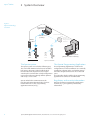
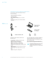
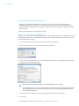
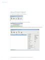
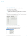
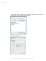
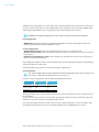
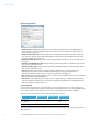
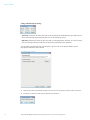
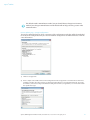
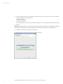
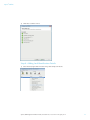
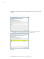
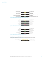
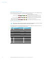
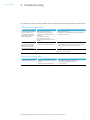
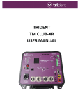
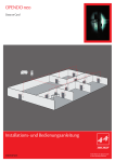
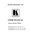
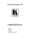
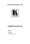
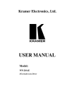
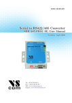
Aperio Offline Quick Installation Guide ® Document No: ST-001802-G, Issue date: 4 July 2014 The global leader in door opening solutions Aperio ® Offline Table of Contents 1Introduction.............................................................................................................................................. 3 Purpose..................................................................................................................................................................................3 Scope......................................................................................................................................................................................3 Applicable Products..........................................................................................................................................................3 Product availability............................................................................................................................................................3 Aperio support in the EAC system...............................................................................................................................3 Abbreviations and Definitions.......................................................................................................................................3 References............................................................................................................................................................................3 2 System Overview .................................................................................................................................... 4 The Aperio system.............................................................................................................................................................4 The Aperio Programming Application.......................................................................................................................4 Regulatory and security information..........................................................................................................................4 3 Quick Installation of Aperio offline locks........................................................................................ 5 Information of encryption key......................................................................................................................................5 Checklist for quick installation of offline locks........................................................................................................6 Preparation before quick installation.........................................................................................................................7 Step 1 - Creating a new installation............................................................................................................................7 Step 2 - Connecting to an offline lock........................................................................................................................8 Step 3 - Configuring locks Wizard................................................................................................................................9 RFID configuration...................................................................................................................................................................... 10 General settings.......................................................................................................................................................................... 13 Scheduled Open & Schedule Data............................................................................................................................................ 13 Security Mode Settings.............................................................................................................................................................. 14 Device update page – Saving Configuration.......................................................................................................................... 15 Step 4 - Adding Lock Identification Details........................................................................................................... 17 Step 5 - Applying a stored configuration to a lock.............................................................................................. 19 Step 6 - Testing after configuration.......................................................................................................................... 21 4 LED Indications.......................................................................................................................................22 Offline Lock LED Indication.......................................................................................................................................... 22 Lock Maintenance LED Indication............................................................................................................................. 23 Lock self test LED indication........................................................................................................................................ 24 5Troubleshooting ....................................................................................................................................25 When connecting to a lock......................................................................................................................................... 25 During normal operation............................................................................................................................................. 25 2 Aperio® Offline Quick Installation Guide, Document No: ST-001322-G Date: 4 July 2014 Aperio® Offline 1 Introduction Purpose The main purpose of this manual is to provide necessary information for a quick installation of Aperio Offline based products using the Aperio Programming Application. The manual is intended for installation personnel, project managers and people with similar responsibilities. Scope This quick installation guide covers a standard installation of a complete Aperio offline system. For a complete description of all functionality and possible settings in an Aperio Offline installation, refer to the Aperio Programming Application Manual, ref [1]. This manual is applicable to version 2.6.6 of the Aperio Programming Application. Applicable Products This manual can be used for all Aperio Offline locks. Product availability The products included in this manual may not be available on all markets. Please check your local ASSA ABLOY company for details. Aperio support in the EAC system Note that the Aperio support may vary depending on the Aperio hardware used and the level of integration. Please contact your OEM for details. Abbreviations and Definitions Abbreviation EAC RFID Definition Electronic Access Control. The system controlling the access rules which is then conveyed to user cards through the Offline Updater. Radio Frequency Identification. The credential technology used. References [1] [2] ST-001321-Aperio Programming Application Manual Aperio Offline System Description Aperio® Offline Quick Installation Guide, Document No: ST-001322-G Date: 4 July 2014 3 Aperio ® Offline 2 System Overview Figure 1. Aperio technology overview Programming application IEEE802.15.4 (2.4GHz) Communication Hub Offline updater RFID card Aperio® OFFLINE RFID card EAC system (Electronic Access Control) Aperio® ONLINE The Aperio system The Aperio Programming Application Aperio online locks communicate to the EAC through communication hubs, for more information refer to the Programming Application manual, ref [1]. Regulatory and security information The Aperio system is used in the following way: The user holds an RFID card in front of an offline lock. Access decision is taken locally by lock. Result of decision depends on access rights stored on the card and also on lock configuration received from the EAC through offline updaters with setup- or user cards. 4 RS-485, Wiegand or Ethernet The Programming Application is used for the configuration of a door installation. It is normally installed on a laptop and is used with an Aperio USB radio dongle connected to one of the USB ports. The USB radio dongle enables the programming application to connect to an offline lock. Refer to the Aperio Programming Application manual, ref [1], for regulatory and security information. Aperio® Offline Quick Installation Guide, Document No: ST-001322-G Date: 4 July 2014 Aperio® Offline 3 Quick Installation of Aperio offline locks After the hardware installation of the locks, the Aperio Programming application is used to configure the locks for use in an access control system. Optionally a lock setup card might be used as a first step to make a fast but limited configuration before the configuration with the Aperio Programming application is done. This chapter will guide installation personnel to configure Aperio Offline locks using the Programming Application, with default settings for an offline access control system: RFID user card (setting of RFID Key and configuration), scheduled open and secure communication. Perform all instruction steps in this chapter to complete an installation. All advanced settings are described in the Aperio Programming Application manual, ref [1]. Information of encryption key To obtain secure communication between the Programming Application and locks an Encryption key is used. This Encryption Key should be handled with the same care as the Master Key in a traditional Master Key System. A person with access to the Encryption key can gain unauthorized access to any Aperio door in the system. Once loaded into the Programming Application, it will be stored encrypted in a local database and any copy should be erased from the hard drive or e-mail. It is however recommended that a copy of the encryption key is stored in safe. The encryption key file is delivered from your local ASSA ABLOY company and should be requested on a customer/site basis. Proper handling of encryption keys is essential to lock/sensor security! It is absolutely necessary to use the customer encryption key by setting all locks in Customer mode to ensure a secure and encrypted communication with the lock. Aperio® Offline Quick Installation Guide, Document No: ST-001322-G Date: 4 July 2014 5 Aperio ® Offline Checklist for quick installation of offline locks To communicate with, and configure locks you need the following: ∙∙ Aperio Programming application ∙∙ USB Radio dongle ∙∙ Radio activation card ∙∙ RFID (MIFARE Classic/DESFire) user card for testing ∙∙ Encryption key (from your local ASSA ABLOY company) Figure 2. Equipment needed Programming application Lock Tritech TriBee USB dongle R A complete quick installation includes the following steps: ∙∙ Preparation: Installation of software and powering the Aperio hardware. ∙∙ Step 1: creating a new installation ∙∙ Step 2: connecting to an offline lock ∙∙ Step 3: configuring locks Wizard: RFID configuration, scheduled open, setting security mode ∙∙ Step 4: adding lock identification data: lock id and lock group ∙∙ Step 5: apply saved configuration to several locks ∙∙ Step 6: testing after configuration 6 RFID card Radio activation card For some configurations a number of additional advanced settings can be necessary, such as advanced lock settings and configuration of the radio communication. These and other settings are described in the Aperio Programming Application manual, ref [1]. The quick installation process does NOT require that the Aperio hardware is configured in the EAC, nor mechanically installed. Aperio® Offline Quick Installation Guide, Document No: ST-001322-G Date: 4 July 2014 Aperio® Offline Preparation before quick installation ∙∙ Install the Programming Application on your laptop. Refer to ref [1], Aperio Programming Application manual for instructions. The software and encryption key file is delivered from your local ASSA ABLOY company. (The encryption key file is provided via encrypted e-mail or on a USB memory stick.) ∙∙ Make sure that batteries are installed in the lock. Step 1 - Creating a new installation The first step is to create a new installation, which is a password protected set of settings you need to communicate with a lock. The installation is linked to the encryption file that is needed in order for the communication to work. 1) Insert the USB Radio dongle and start the Aperio Programming Application. 2) Select File–New Installation... in the Aperio Programming Application. 3) Enter a name for the installation, a password matching the requirements and finally click the button in the Key file field to add the Encryption key. Proper handling of encryption keys is essential to lock/sensor security! It is absolutely necessary to use the customer encryption key by setting all communication hubs and locks/sensors in Customer mode to ensure a secure and encrypted communication with the lock/sensor. 4) Select the key file and click Select. (The xml-file (key file) containing the encryption keys.) 5) Click Create. Aperio® Offline Quick Installation Guide, Document No: ST-001322-G Date: 4 July 2014 7 Aperio ® Offline Step 2 - Connecting to an offline lock Follow these steps to connect to an offline lock: 1) Click Connect in the Offline section of the menu bar. 2) Hold the radio card at the lock (or remove and reinsert battery). Result: Detailed information is downloaded and the Programming application connects to the lock. 8 Aperio® Offline Quick Installation Guide, Document No: ST-001322-G Date: 4 July 2014 Aperio® Offline Step 3 - Configuring locks Wizard This instruction describes a default configuration of a lock and includes the following settings: ∙∙ RFID user card (setting of RFID Key and configuration) - RFID configuration dialog. ∙∙ Site code and time zone - General settings dialog. ∙∙ Scheduled open - Configure Schedule open settings & schedules dialog ∙∙ Secure communication - Security Mode Settings dialog. Everything is skipped (without changes) in this workflow by clicking Next except Time zoneDaylight saving time data and Time and date (UTC) For other settings other than mentioned here, refer to the Aperio Programming Application manual, ref [1]. ∙∙ Before configuration, check that default radio channels are used (11, 16 and 26). On the menu bar, click Settings-Offline Installation settings to enter this dialog. Follow the steps below to perform a default configuration of locks: The changes you make during the update of the door configuration are not carried out until you perform the device update on the last page in the wizard. 1) Select the lock in the scan result table, right-click and select Configure... Aperio® Offline Quick Installation Guide, Document No: ST-001322-G Date: 4 July 2014 9 Aperio ® Offline 2) Click Next after completion of each dialog in the Configuration Wizard. RFID configuration Select the tab depending upon the lock type. Only one type of configuration can be sent to the Lock. Click Add/Change... to enter the settings for each card format. MIFARE Classic configuration 10 Aperio® Offline Quick Installation Guide, Document No: ST-001322-G Date: 4 July 2014 Aperio® Offline MIFARE Classic configurations is a part of the lock setup information that describes the sector layout of access cards used on the site. This configuration screen allows the user to specify a MIFARE 'B' key and configure the MIFARE-sector usage (alarm sectors and schedule open sectors). If MIFARE Classic RFID configuration is done wrong, the lock may become inoperable. Key configuration: ∙∙ MIFARE Key B: Enter the 6 byte long hexadecimal MIFARE Classic Key B that applies for the user cards in your installation. Example: AABBCC112233. Sector configuration: ∙∙ Total number of sectors: Enter the total number of sectors to be used on the card. ∙∙ Number of alarm sectors: Enter the number of alarm sectors reserved on access cards used on the particular site. ∙∙ Number of scheduled open sectors: Enter number of scheduled open sectors reserved on access cards used on the particular site. After adding the number of sector used, click the Physical number drop down menu to select/change a physical number for each sector. Physical numbers not used are free to be used by other applications. System limitation The sector configuration settings affect the number of lock groups that can be used (see section "Step 4 - Adding Lock Identification Details" on page 17). Plan your sector configuration with the following limitations in mind: MIFARE Classic 1K MIFARE Classic 4K Max lock units 65536 65536 Max lock groups 1344 5088 Max alarms 84 420 Having max lock groups means no alarms and vice versa since they share the same storage space on the credential. It is up to the system owner to ensure that the appropriate number of sectors needed to represent all doors are reserved on all user credentials in the system. It is recommended to add extra sectors not reserved for alarms/schedules, in order to obtain space for lock group addressing. Each free sector allows 96 lock groups (MIFARE Classic 1K card). Aperio® Offline Quick Installation Guide, Document No: ST-001322-G Date: 4 July 2014 11 Aperio ® Offline DESFire Configurations ∙∙ Application ID: Identification number for the Programming application on the MIFARE DESFire cards used in the system. A MIFARE DESFire card can have up to 32 applications. Application ID:s range from 0 to 16777215. ∙∙ File Data Protection Level: Security level for the communication between lock and card. Choose one of the two options (Data Authenticity by MAC, Full Encryption) depending on how the cards used in the system are configured. ∙∙ Number of alarm slots: Numeric value representing number of alarm slots on access cards used in the system. ∙∙ Number of scheduled open slots: Numeric value representing number of scheduled open slots on access cards used in the system. ∙∙ Number of lock groups: Numeric value representing maximum number of allowed lock groups on access cards used in the system. ∙∙ Key Type: Choose one of the three options (2K3DES, 3K3DES, AES-128) depending on the cryptographic algorithm used to read/write data from/to the card. Type the key value in hexadecimal. 2K3DES and AES-128 are 16 byte keys. 3K3DES is a 24 byte key. ∙∙ Key: MIFARE DESFire key that applies for the user cards in your installation in HEX format. Example:0 0112233445566778899aabbccddeeff ∙∙ Key Number: Each application can use up to 14 keys. Key 0 is always the Application's Master Key. Type here which key number that is used for the Programming application on the MIFARE DESFire cards. Key numbers range from 0 to 13. System limitation It is up to the system owner to assure that there is space enough on the access cards used for the actual system configuration. Possible configurations are dependent on the size of the MIFARE DESFire EV1 cards used in the system and if they are used for other applications than Aperio Offline. Plan your sector configuration with the following limitations in mind: MIFARE DESFire 2K MIFARE DESFire 4K MIFARE DESFire 8K Max lock groups 4000 8096 16288 Max alarm slots 250 506 1018 Max scheduled open slots 500 1012 2036 Having max lock groups means no alarms and vice versa since they share the same storage space on the credential. 12 Aperio® Offline Quick Installation Guide, Document No: ST-001322-G Date: 4 July 2014 Aperio® Offline General settings ∙∙ Site code settings: Each site has a unique code that all credentials within the system share. It is a mandatory field on the screen where the user is allowed to enter up to 4 bytes (9-10 digits) . ∙∙ Time zone settings: Select the time zone where the access system is located. Configure Scheduled Open settings & schedules Aperio® Offline Quick Installation Guide, Document No: ST-001322-G Date: 4 July 2014 13 Aperio ® Offline Change Scheduled open settings ∙∙ Start time: Start time for when the lock can be activated for scheduled open (For when access cards with scheduled open functionality can set the lock to be open). ∙∙ End time: End time for when the lock responds to scheduled open attempts. It is also the time when the lock goes back to locked state after being scheduled open unlocked. The schedule open function has several options, please refer to the Aperio Offline System Description manual for more details. Security Mode Settings 1) Click Change in the Security Mode Setting area if you want to change the security mode, or click Next. 2) To change to customer mode, click the check box and click OK. 14 Aperio® Offline Quick Installation Guide, Document No: ST-001322-G Date: 4 July 2014 Aperio® Offline The default mode is Manufacturer mode, but you should always change it to Customer mode. If you change to Manufacturer mode the lock will no longer be using secure radio communication. Device update page – Saving Configuration The Device Update dialog box shows a summary of the configuration tasks that will be downloaded to the lock. The configuration may be saved to facilitate configuration of additional devices with the same information. 1) Click Save configuration. 2) Enter a unique and suitable name for this configuration in the Configuration name field. Choose this name carefully, to make it clear what settings are changed in the lock/sensor or communication hub. You could, for instance, name it according to the different configuration tasks or, if applicable, use a name that reflects the specific door type. Aperio® Offline Quick Installation Guide, Document No: ST-001322-G Date: 4 July 2014 15 Aperio ® Offline 3) Exclude configurations settings by clicking the check boxes. Only save settings that are general for all locks in your installation. A recommendation is: a) RFID configuration b) Change security mode c) Device time update d) And optionally some advanced features like Battery Alarm, Status configuration and Locking parameters 4) Click OK. Result: The configuration is saved in the local storage, and you are back in the Configuration Wizard. Choosing Cancel on the Device Update page does not affect the locally stored configuration. 5) Click Next to download the configuration to the lock. 6) Hold the radio card at the lock (or remove and reinsert battery). 16 Aperio® Offline Quick Installation Guide, Document No: ST-001322-G Date: 4 July 2014 Aperio® Offline 7) Click Close to exit the wizard. Step 4 - Adding Lock Identification Details 1) Select the lock, right-click and select Change lock identification details. Aperio® Offline Quick Installation Guide, Document No: ST-001322-G Date: 4 July 2014 17 Aperio ® Offline 2) Enter the lock identification details either Manually or through Imported data by selecting one of the radio buttons. a) Manually: Enter Physical Location (max 21 alpha numeric characters), Lock Id (max 5 numeric characters, 2 bytes: 0-65535), Lock Group (max 5 numeric characters, 2 bytes: 0-65535, & max value decided by RFID configurations) b) Imported data: This is an advanced option where imported door data (XML format) can be used to configure locks, see ref [1] ST-001321-Aperio Programming Application manual. 3) Click OK. 18 Aperio® Offline Quick Installation Guide, Document No: ST-001322-G Date: 4 July 2014 Aperio® Offline 4) Hold the radio card at the lock (or remove and reinsert battery) to download the Physical location data. Step 5 - Applying a stored configuration to a lock If you have more than one lock that will use the same configuration you can apply the previously saved configuration on any lock in your installation. 1) Connect to another lock that you want to apply a saved configuration on. In the Installation view, right-click the new lock and select Apply configuration and choose an earlier stored configuration. Aperio® Offline Quick Installation Guide, Document No: ST-001322-G Date: 4 July 2014 19 Aperio ® Offline 2) Click Confirm to start the transfer. 3) Hold the radio card at the lock (or remove and reinsert battery) to download the configuration. 4) After download, the result is shown. The settings that could not be downloaded to the specific hardware are ignored. Click OK to finish. 5) Add Physical location, Lock id and Lock Group according to section "Step 4 - Adding Lock Identification Details" on page 17. 6) Repeat all the steps from the beginning of this section for every lock you want to configure with a saved configuration. 20 Aperio® Offline Quick Installation Guide, Document No: ST-001322-G Date: 4 July 2014 Aperio® Offline Step 6 - Testing after configuration Follow these steps to test that the configuration of each lock has been performed correctly and that the hardware is working: 1) Hold a credential that is invalid in the EAC system in front of the lock. Result: Access is denied and the lock LED flashes red once. Access denied One red flash (1 second) 2) Hold a credential that is valid in the EAC system in front of the lock. Result: Access is granted and the lock LED flashes green once. Access granted One green flash (1 second) See section "4 LED Indications" on page 22 for details on the different LED indications. Aperio® Offline Quick Installation Guide, Document No: ST-001322-G Date: 4 July 2014 21 Aperio ® Offline 4 LED Indications Offline Lock LED Indication The Aperio Offline lock has a single LED that supports an optical scheme with red, green and yellow. The indication scheme differs depending on the credential type presented at the lock: Access granted Access denied Open lock permanently1) In toggle mode: Close lock1) Access denied1) One green flash (1 sec.) One red flash (1 sec.) One green flash (1 sec.) One yellow flash (.125 sec.) One red flash (1 sec.) Scheduled open enabled card (first swipe): Scheduled open unlocked Second swipe (within 2 - 5 s): Scheduled open unlocked/locked One yellow flash (.125 sec.) Four green flashes (.25 sec.) Lock mechanism is blocked when closing2) Continuous red flashes (.125 seconds every 1 sec.) Error in lock, maintenance required3) Ten red flashes (.125 sec. each) (Repeated every 10 sec. if lock can’t close) Tamper Ten red flashes (.125 sec. each) repeated every 10 sec. Time to replace the battery Continuous yellow flashes (.25 seconds every 5 sec.) Battery reached end of life, lock disabled Continuous red flashes (.25 seconds every 5 sec.) Figure 3. Offline lock LED indication - Access cards 1) If LED or LED/Buzzer is configured as card read indication, an extra yellow indication will be shown compared to description above. 2) When the lock mechanism is blocked (lock jammed) the knob must be turned to release it. 3) The “Error in lock” indication is also shown instead of the POST flashes if the battery is not accepted as new after a power-on-reset. 22 Aperio® Offline Quick Installation Guide, Document No: ST-001322-G Date: 4 July 2014 Aperio® Offline Radio activation card read One yellow flash (1 sec.) UHF transceiver activated Yellow flashes (.25 second repeated for 1 min) Programming Application connected to lock Green flashes (.25 second every sec. for 1 min) Figure 4. Offline lock LED indication - Radio activation card Card detected One yellow flash (0.125 sec.) Card read OK One green flash (1 second) Card read FAILED One red flash (1 second) Figure 5. Offline lock LED indication - Void list card Card detected One yellow flash (0.125 sec.) Card read OK One green flash (1 second) Card read/write FAILED One red flash (1 second) Figure 6. Offline lock LED indication - Audit Trail card Lock Maintenance LED Indication Some special LED indication schemes are used during lock maintenance actions: Enter configuration mode Five yellow flashes (.125 second each) Aperio® Offline Quick Installation Guide, Document No: ST-001322-G Date: 4 July 2014 23 Aperio ® Offline Lock self test LED indication After replacing the battery, a Power on Self Test (POST) is performed. The result is indicated using a series of red and green LED flashes as is described by the figure below: POST Successful Failure during POST Battery not fully charged Energy counter not reset No power on self test done ... ... ... One red, one green flash (1 second), and yellow flashes for 20 seconds (UHF activated) ... One red flash, 16 red or green flashes (.5 second), and yellow flashes for 20 seconds (UHF activated) ... 10 red flashes (125ms), followed by yellow flashes for 20 seconds (UHF activated) Figure 7. Lock POST LED indication If the battery is not accepted as new after a power on reset, no POST is performed, instead the 10 quick red flashes used to indicate “Error in lock” is shown. The first flash is always red. If the POST fail, the color of the 16 trailing flashes indicate the status of each individual test as described by the following table: Blink 1 2 3 4 5 6 7 8 9 10 11 12 13 14 15 16 17 24 Meaning if red POST initiation flash Main board firmware corrupt Reserved for future use Production data corrupt Production data corrupt Configuration data corrupt Load circuit corrupt Configuration data corrupt Secure area key error Secure area motor error Secure area communication error Secure area memory error Secure area motor sensor error Radio modem communication error Radio modem memory corrupt Radio modem EEPROM corrupt Radio modem RF error Code in event log 0x0001 0x0002 0x0004 0x0008 0x0010 0x0020 0x0040 0x0080 0x0100 0x0200 0x0400 0x0800 0x1000 0x2000 0x4000 0x8000 Aperio® Offline Quick Installation Guide, Document No: ST-001322-G Date: 4 July 2014 Aperio® Offline 5 Troubleshooting The tables below show possible problems when using the Aperio technology, and how to solve them: When connecting to a lock Problem indication The lock is not found when trying to connect = no connection between the programming application/ laptop and the lock. Unstable communication between lock and Radio dongle even though the MAC address is displayed after connecting to lock. The device update fails Cause ∙∙ All radio channels are busy. ∙∙ The programming application and the lock have different radio channels. ∙∙ The lock is not working. ∙∙ The lock is not powered. ∙∙ The lock is out of range of the USB dongle. ∙∙ A probable cause is bad radio conditions or limited radio range. Radio not activated in lock Action 1.Click Connect again. 2. Change the radio channels. See the Programming Application manual. ∙∙ Try moving the USB radio closer to the lock. Either by moving the laptop or by using an A-A USB extension cable to distance the USB radio from the PC. Perform device update again and show the radio activation card to the lock. During normal operation Problem indication The lock LED is flashing red. Cause Action ∙∙ The battery of the lock/sensor has ∙∙ Change the battery of the lock. See the ∙∙ Hardware failure/Lock jammed ∙∙ Service the lock. run out. Programming Application manual. Aperio® Offline Quick Installation Guide, Document No: ST-001322-G Date: 4 July 2014 25 ASSA ABLOY is the global leader in door opening solutions, dedicated to satisfying end-user needs for security, safety and convenience Contact www.assaabloy.com/aperio Wireless lock technology