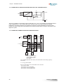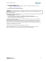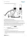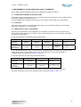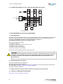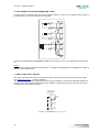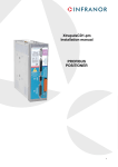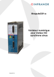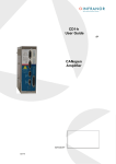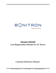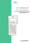
1
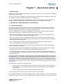
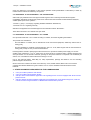
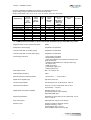
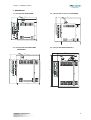
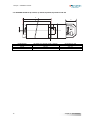
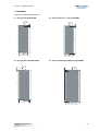
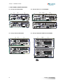
CD1-pm Installation manual gb PROFIBUS POSITIONER INFRANOR® CD1-pm 1 CD1-pm – Installation manual WARNING ! This is a general manual describing a series of servo amplifiers having output capability suitable for driving AC brushless sinusoidal servo motors. Instructions for storage, use after storage, commissioning as well as all technical details require the MANDATORY reading of the manual before getting the amplifiers operational. Please see CD1-pm User Guide for the operation of the amplifier (commissioning, configuration…). For the PROFIBUS communication, see manual CD1-pm – PROFIBUS Communication Profile. Maintenance procedures should be attempted only by highly skilled technicians having good knowledge of electronics and servo systems with variable speed (EN 60204-1 standard) and using proper test equipment. The conformity with the standards and the "CE" approval is only valid if the items are installed according to the recommendations of the amplifier manuals. Connections are the user's responsibility if recommendations and drawings requirements are not met. Any contact with electrical parts, even after power down, may involve physical damage. Wait for at least 5 minutes after power down before handling the amplifiers (a residual voltage of several hundreds of volts may remain during a few minutes). ESD INFORMATION (ElectroStatic Discharge) INFRANOR amplifiers are conceived to be best protected against electrostatic discharges. However, some components are particularly sensitive and may be damaged if the amplifiers are not properly stored and handled. STORAGE - The amplifiers must be stored in their original package. When taken out of their package, they must be stored positioned on one of their flat metal surfaces and on a dissipating or electrostatically neutral support. Avoid any contact between the amplifier connectors and material with electrostatic potential (plastic film, polyester, carpet…). HANDLING - If no protection equipment is available (dissipating shoes or bracelets), the amplifiers must be handled via their metal housing. Never get in contact with the connectors ELIMINATION In order to comply with the 2002/96/EC directive of the European Parliament and of the Council of 27 January 2003 on waste electrical and electronic equipment (WEEE), all INFRANOR devices have got a sticker symbolizing a crossed-out wheel dustbin as shown in Appendix IV of the 2002/96/EC Directive. This symbol indicates that INFRANOR devices must be eliminated by selective disposal and not with standard waste. INFRANOR does not assume any responsibility for any physical or material damage due to improper handling or wrong descriptions of the ordered items. Any intervention on the items, which is not specified in the manual, will immediately cancel the warranty. Infranor reserves the right to change any information contained in this manual without notice. © INFRANOR, September 2008. All rights reserved. Issue: 8.6 2 CD1-pm – Installation manual Contents PAGE CONTENTS............................................................................................................................................. 3 CHAPTER 1 – GENERAL DESCRIPTION............................................................................................. 5 1 - INTRODUCTION............................................................................................................................. 5 2 - DESCRIPTION / COMPLIANCE WITH THE STANDARDS............................................................ 5 2.1 - GENERAL DESCRIPTION....................................................................................................... 5 2.2 - REFERENCE TO THE STANDARDS: "CE" CERTIFICATION ............................................... 6 2.3 - REFERENCE TO THE STANDARDS: "UL" LISTING ............................................................. 6 3 - OTHER DOCUMENTS REQUIRED FOR THE COMMISSIONING ................................................ 6 CHAPTER 2 – SPECIFICATIONS.......................................................................................................... 7 1 - MAIN TECHNICAL DATA................................................................................................................ 7 1.1 - CD1-pm-230-/I POSITIONER................................................................................................... 7 1.2 - CD1-pm-400/I POSITIONER.................................................................................................... 7 1.3 - COMMON SPECIFICATIONS TO BOTH POSITIONER VERSIONS CD1-pm-230/I AND CD1-pm-400/I ................................................................................................................................... 8 2 - DIMENSIONS................................................................................................................................ 11 2.1 - CD1-pm-230/I POSITIONER…. ............................................................................ 11 2.2 - CD1-pm-400/1.8 TO 7.2 A POSITIONER .............................................................................. 11 2.3 - CD1-pm-400/14 A POSITIONER…. ....................................................................... 11 2.4 - CD1-pm-400/30/45/70 AND 90 A POSITIONER ................................................................... 11 2.5 - BRAKING RESISTOR dp 100/100, dp 200/100, dp 50/200, dp 33/280 and EF 400............. 12 3 - FASTENING.................................................................................................................................. 13 3.1 - CD1-pm-230/I POSITIONER…. ............................................................................ 13 3.2 - CD1-pm-400/1.8 TO 7.2 A POSITIONER .............................................................................. 13 3.3 - CD1-pm-400/14 A POSITIONER…. ....................................................................... 13 3.4 - CD1-pm-400/30/45/70 AND 90 A POSITIONER ................................................................... 13 4 - MULTIAXES CABINET MOUNTING ............................................................................................. 14 4.1 - CD1-pm-230/I POSITIONER….. ........................................................................... 14 4.2 - CD1-pm-400/1.8 to 7.2 POSITIONER.................................................................................... 14 4.3 - CD1-pm-400/14 POSITIONER….. ......................................................................... 14 4.4 - CD1-pm-400/30/45/70 AND 90 A POSITIONER ................................................................... 14 CHAPTER 3 - INPUTS - OUTPUTS ..................................................................................................... 15 1 - CONNECTORS LOCATION ......................................................................................................... 15 2 - LEDS.............................................................................................................................................. 16 2.1 - AMPLIFIER FAULT LEDs ...................................................................................................... 16 3 - X1: RESOLVER CONNECTOR .................................................................................................... 16 4 - X2: DIGITAL I/OS CONNECTOR .................................................................................................. 17 5 - X3: ENCODER CONNECTOR ...................................................................................................... 19 5.1 - X3 CONNECTOR FOR TTL INCREMENTAL ENCODER & HES INPUT (Sub D 25 pins female) ............................................................................................................................................ 19 5.2 - X3 CONNECTOR FOR SinCos INCREMENTAL ENCODER & HES INPUT (Sub D 25 pins female) ............................................................................................................................................ 20 5.3 - X3 CONNECTOR FOR ABSOLUTE SINGLE TURN SIN/COS ENCODER (Sub D 25 pins female) ............................................................................................................................................ 21 5.4 - X3 CONNECTOR FOR ENCODER OUTPUT (Sub D 25 pins female) ................................. 22 6 - X4: COMMAND CONNECTOR ..................................................................................................... 23 6.1 - SPECIFICATIONS OF THE LOGIC INPUTS: FC+, FC-, INDEX, ENABLE, RESET ............ 23 6.2 - SPECIFICATION OF THE "AOK" LOGIC RELAY OUTPUT ................................................. 24 7 - X5: RS-232 CONNECTOR ........................................................................................................... 24 8 - X6: PROFIBUS.............................................................................................................................. 24 9 - X8: AUXILIARY SUPPLY AND BRAKE CONNECTOR ................................................................ 24 3 CD1-pm – Installation manual 10 - X9: POWER CONNECTOR: MAINS, MOTOR, BRAKING RESISTOR (CD1-PM-230 V & 400 V) ........................................................................................................................................................... 25 CHAPTER 4 - CONNECTIONS ............................................................................................................ 26 1 - CONNECTION DIAGRAMS .......................................................................................................... 26 1.1 - CD1-pm-230/I POSITIONER.................................................................................................. 26 1.2 - CD1-pm-400/I POSITIONER.................................................................................................. 27 1.3 - SERIAL LINK CONNECTION................................................................................................. 27 1.4 - CONNECTION OF A BACKUP BATTERY FOR THE 24 VDC AUXILIARY SUPPLY .......... 28 1.5 - CONNECTION EXAMPLE FOR A MULTIAXIS APPLICATION ........................................... 28 2 - WIRING RECOMMENDATIONS................................................................................................... 29 2.1 - GROUND CONNECTIONS AND GROUNDING.................................................................... 29 2.2 - CONNECTORS SHIELD CONNECTION............................................................................... 30 2.3 - CONNECTION VIEW OF CD1-pm-400/30/45/70 and 90 A................................................... 31 2.4 - MOTOR, RESOLVER AND ENCODER CABLES ................................................................. 31 2.5 - SERIAL LINK CABLES........................................................................................................... 32 2.6 - CONNECTION CABLES OF THE BRAKING RESISTOR ..................................................... 32 3 - REQUIREMENTS OF COMPLIANCE WITH THE UL STANDARDS............................................ 33 3.1 - CONNECTION BY MEANS OF FASTON SOCKET .............................................................. 33 3.2 - 24 V SUPPLY ......................................................................................................................... 33 3.3 - POWER SUPPLY AND UL FUSE RATING ........................................................................... 33 3.4 - CD1-pm-230/I DRIVE: CONNECTION DIAGRAM WITH PROTECTIONS BY "UL" FUSES 34 3.5 - CD1-pm-400/I DRIVE: CONNECTION DIAGRAM WITH PROTECTIONS BY "UL" FUSES 35 3.6 - CONNECTION EXAMPLE FOR A UL COMPLIANT MULTIAXIS APPLICATION ................ 36 4 - FIRST POWERING OF THE CD1-PM POSITIONER .................................................................... 36 4.1 - VERY IMPORTANT................................................................................................................ 36 4.2 - SWITCH ON THE 24 VDC SUPPLY..................................................................................... 36 4.3 - SWITCH ON THE 230 VAC OR 400 VAC SUPPLY (according to the positioner type). ....... 36 4.4 - FURTHER COMMISSIONING PROCEDURE ...................................................................... 36 CHAPTER 5 – APPENDIX.................................................................................................................... 37 1 - HARDWARE ADJUSTMENTS OF THE LOGIC BOARD .............................................................. 37 2 - ADJUSTMENT TO VARIOUS RESOLVER TYPES ...................................................................... 38 3 - USE OF THE "AOK" OUTPUT ...................................................................................................... 38 4 - ENERGY RECUPERATION VIA A BRAKING RESISTOR ........................................................... 39 5 - ORDER CODE .............................................................................................................................. 39 4 Contents CD1-pm – Installation manual Chapter 1 – General description 1- INTRODUCTION Series CD1-pm Profibus positioners are PWM servo amplifiers for the control of AC sinusoidal motors (brushless) equipped with a position sensor. The CD1-pm servo drive is available as a stand-alone single-axis block that includes all supplies and mains filter. It is available in both mains operated versions 230 VAC and 400/480 VAC. The CD1-pm positioner operates with a PROFIBUS DP interface or in stand-alone by using only digital I/Os. It generates itself the positioning trajectory that allows the programming of 128 positioning sequences. 2 – DESCRIPTION / COMPLIANCE WITH THE STANDARDS 2.1 - GENERAL DESCRIPTION The CD1-pm amplifier directly controls the motor torque and speed by means of the information provided by a high resolution position sensor (resolver or encoder). The sinusoidal current commutation based on this high resolution position sensor provides very smooth motor torque/force control. The CD1-pm amplifier can be configured for the feedback of various position sensor types. The appropriate position sensor configuration is selectable by software and saved in the amplifier. - With a resolver sensor feedback, the motor absolute position value over one revolution is available and the servo motor can immediately be enabled after the amplifier power up. - With a "SinCos tracks" sensor which provides two analog Sin and Cos signals electrically compliant with the SinCos encoder signals and which period is equal to the motor pole pitch, the servo-motor can be immediately enabled after the powering of the drive. - With an absolute single-turn SinCos encoder feedback (Heidenhain ERN 1085 or compliant), the servo motor can also immediately be enabled after the amplifier power up. - With an incremental encoder only, a motor phasing procedure (Phasing) must be executed at each amplifier power up before the motor enabling. - With an incremental encoder + Hall Effect Sensors (HES) feedback, the motor phasing procedure is no more necessary and the servo motor can immediately be enabled after the amplifier power up. - With an absolute single-turn, multi-turn or linear encoder using the ENDAT or HIPERFACE communication protocols and fitted with incremental SinCos outputs, the servo-motor can also be immediately enabled after the powering of the drive. Series CD1-pm positioners have their own DC/DC converter to provide appropriate logic voltage to the modules. An auxiliary 24VDC +/- 15 % supply is generally available on all machines and supplies a DC/DC converter with all logic supplies required by the positioner. The auxiliary supply allows to keep the logic board on, after the power supply has been switched off, in order to keep all parameters in the memory and to avoid initializing the machine all over again. A 24 VDC battery supply with specific wiring allows to keep the position even after switching off the auxiliary 24 VDC supply. This wiring can be used for "absolute" operation with the CD1-pm positioner (see chapter 4: Connections). The power supply is depending on the positioner type: • CD1-pm-230/I: 230 VAC single-phase mains operation power supply or three-phase via a transformer or an autotransformer (or direct three-phase mains operation if there are three-phase mains available in 200 to 230 VAC). • CD1-pm-400/I: 400 to 480 VAC three-phase mains operated power supply. A soft start system of the power supply allows to limit the inrush current at power on. The very small dimensions of the CD1-pm positioner allow an optimum integration in 300 mm deep cabinets (connectors included). The CD1-pm positioner operates with a PROFIBUS DP interface or in stand-alone by using Chapter 1 - General description 5 CD1-pm – Installation manual using only digital I/Os. The selection of the various operation modes (PROFIBUS or stand-alone) is made by means of micro-switches accessible by the operator. 2.2 - REFERENCE TO THE STANDARDS: "CE" CERTIFICATION Series CD1-pm positioners have been approved with regard to their conformity with the Electromagnetic Compatibility standards concerning the power servos referenced in the EN 61800-3:2004 standard "Electrical variable speed power servo systems": - EN 55011, group 1, C3 category, regarding radiated radioelectric disturbances, - EN 61000.4-2-3-4-5 regarding immunity. Standard to be applied to the electrical equipment of industrial machines: EN 60204-1. These items have been "CE" marked since year 2000. 2.3 - REFERENCE TO THE STANDARDS: "UL" LISTING CD1-pm series have been “CULUS” listed according to UL508C, and UL840 regarding the insulator. This product was evaluated to: - the Third Edition of UL508C, the UL Standard for Power Conversion Equipment, dated May 2002 for the UL Listing (USL), - the CSA Standard for Industrial Control Equipment, C22.2 N° 14-95, dated August 1995 for the Canadian UL Listing (CNL) except for CD1-pm-400/70 and 90 drives. Providing that the manual is specifying that the end user has to provide an isolated power supply, for 24 VDC auxiliary input protected by a 4 A UL Listed fuse, the power board is considered within a limited voltage/current circuit per section 31.4 of UL508C. Therefore, spacings on the power board are not required to be evaluated per section 31.2 of UL508C and were evaluated according to UL 840. Per UL 840 (Second Edition, dated May 20, 1993) requirements, spacings are limited to 2.5 mm assuming pollution degree 2 environment. Ground connection is fixed in the frame of the device by a rivet, Avibulb masse, BN10-5168. The connector complies with standard dimensions given in table 6.2 of UL 310, the standard for Electrical Quick connect terminals. 3 - OTHER DOCUMENTS REQUIRED FOR THE COMMISSIONING ♦ ♦ ♦ ♦ 6 " CD1-pm Profibus positioner User Manual". " CD1-pm Profibus Communication Profile". "CD1-pm SinCos track feedback" application note regarding the use of motors equipped with "SinCos tracks" position sensors. "CD1-pm absolute encoders feedback" application note regarding the use of absolute single-turn, multi-turn or linear encoders using the ENDAT or HIPERFACE Communication protocols. Chapter 1 - General description CD1-pm – Installation manual Chapter 2 – Specifications 1 - MAIN TECHNICAL DATA 1.1 - CD1-pm-230-/I POSITIONER Mains operated power supply voltage 230 VAC + 10 %/- 15 % 1~ or 3~, 50 - 60 Hz Isolated auxiliary galvanic and motor brake supply voltage 24 VDC +/- 15 % - 320 mA without brake Motor phase-phase output voltage 200 Vrms Integrated braking system External 100 Ohm/100 W braking resistor (dp 100/100) Min. resistance: 50 Ohm (dp 50/200) Minimum inductance between phases 1 mH OUTPUT CURRENT RATINGS (at a maximum room temperature of 40°C) Amplifier type Max. output current (Arms) for 1 sec. +/- 5 % (230 VAC) Rated output current (Arms) (230 VAC) Power losses (W) Rated input current (Arms) (230 VAC, 60 Hz) Max. protection fuses for line circuit RK5 listed (Bussman / Littelfuse) Shortcircuit power of the mains UL listed CD1-pm-230/2.25 CD1-pm-230/4.5 CD1-pm-230/7.5 CD1-pm-230/10.5 CD1-pm-230/16.5 2.25 4.5 7.5 10.5 16.5 1.1 2.25 3.75 5.25 8.25 25 30 44 55 66 1.1 2.25 3.75 5.25 8.25 6A 6A 6A 6A 9A 5 kA 5 kA 5 kA 5 kA 5 kA yes yes yes yes yes 1.2 - CD1-pm-400/I POSITIONER Mains operating power supply voltage 400 to 480 VAC + 10 %/- 15 % 3~, TN or TT system with grounded neutral point 50 to 60 Hz (phase-ground voltage must be balanced) Isolated auxiliary and motor brake supply voltage 24 VDC +/- 15 % - 320 mA without brake Motor phase-phase output voltage 380 to 460 Vrms depending on the mains Integrated braking system CD1-pm-400/1.8 to 7.2 A: External 200 Ohms/100 W resistor (dp 200/100) Minimum resistor value: 150 Ohms/100 W CD1-pm-400/14: External 50 Ohms/200 W resistor (dp 50/200) CD1-pm-400/30/45: External resistor 33Ω/280 W (dp 33/280) CD1-pm-400/70/90: External resistor 16.5Ω/560 W (EF 400) Minimum inductance between phases 2 mH Chapter 2 - Specifications 7 CD1-pm – Installation manual OUTPUT CURRENT RATINGS (at a maximum room temperature of 40°C) Output voltage range for 400-480 VAC (rms) three-phase mains Output current range: 1.8 A, 2.7 A, 5.1 A, 7.2 A, 14 A, 30 A, 45 A, 70 A, 90 A (rms) Amplifier type Max. output current (Arms) for 1 sec. +/- 5 % (480 VAC) Rated output current (Arms) (480 VAC) Power losses (W) Rated input current (Arms) (480 VAC, 60 Hz) Max. protection fuses for line circuit RK5 listed or A60Q40 for 400/70 and 400/90 Short-circuit power of the mains UL listed 1.8 2.7 5.1 7.2 14 30 45 70 90 0.9 1.35 2.55 3.6 7 15 20 35 35 35 43 71 93 200 400 560 650 650 0.9 1.35 2.55 3.6 7 15 20 35 35 2A 2A 4A 4A 8A 20 A 20 A 40 A 40 A 5 kA 5 kA 5 kA 5 kA 5 kA 5 kA 5 kA 5 kA 5 KA yes yes yes yes yes yes yes in progress in progress CD1-pm-400/1.8 CD1-pm-400/2.7 CD1-pm-400/5.1 CD1-pm-400/7.2 CD1-pm-400/14 CD1-pm-400/30 CD1-pm-400/45 CD1-pm-400/70 CD1-pm-400/90 1.3 - COMMON SPECIFICATIONS TO BOTH POSITIONER VERSIONS CD1-pm-230/I AND CD1-pm-400/I Regulation loops: current, speed and position Digital Mains filter on power supply Integrated in the positioner Common mode filter on auxiliary supply Integrated in the positioner Common mode filter on motor brake supply Integrated in the positioner Power stage protections - power supply overvoltage - internal switch protection - short-circuit between motor phases or between motor phase and ground - amplifier overtemperature (on CD1-pm-400/I only) - fan system error - PWM control error - power stage supply error - braking system error Motor brake control Max. 1.5 A with 24 VDC PWM switching frequency 8 kHz Minimum inductance between phases 1 mH for 230 V / 2 mH for 400 V Digital current regulator (PI) Adjusted to the motor Current loop bandwidth Cut-off frequency for 45° phase shift : 1000 Hz Internal current limitation Imax: 20 % to 100 % and Irated: 20 % to 50 % Imax duration = 1 second Digital speed and position regulators Sampling period = 0,5 ms Anti-wind-up system of the integrator Adjustable digital gains Speed loop bandwidth Selectable cut-off frequency for 45° phase shift: 50 Hz, 75 Hz or 100 Hz Max. motor speed Adjustable from 100 rpm to 25 000 rpm Resolver input Position conversion: 65536 ppr (16 bit) Excitation frequency: 8 kHz Transformation ratio: 0.3 to 0.5 (other available values are factory set) 8 Chapter 2 - Specifications CD1-pm – Installation manual Encoder input Selectable by software: Quadrature signals A & B with Z marker pulse RS 422 line receiver Maximum pulse frequency: 1 MHz Resolution: 500 to 106 ppr Incremental Sin/Cos encoder Heidenhain 1Vcc Sin/Cos type or compliant Maximum signal frequency: 200 kHz Resolution: 500 to 106 ppr Interpolation factor: 1024 Absolute single-turn Sin/Cos encoder Heidenhain ERN 1085 or compliant Maximum signal frequency: 200 kHz Resolution: 2048 or 512 ppr Interpolation factor: 1024 Hall sensors input Selectable by software: 120° or 60° HES type 5 V or 12 V supply voltage HES sequence error detection Encoder position output A and B channels in quadrature Z marker pulse: 1 per motor revolution RS-422 line driver Programmable resolution from 64 ppr to 16384 ppr Arc minute accuracy = (8 + 5400/Resolution) Logic inputs - Enable / Disable: ENABLE - Limit switch +: FC+ - Limit switch -: FC- Homing input: INDEX - Reset of a stored fault: RESET - Sequence start: START - Sequence stop: STOP - Programmable inputs : IN1 to IN6 Logic outputs - Sequence in progress: SEQ - Position reached: POS - Speed reached :SPEED - Programmable outputs : OUT1 to OUT4 Analog input +/-10 V resolution 14 bit (1 reconfigurable logic output) On-the-fly speed limitation Polarity selectable by software: -no limitation for 0 Volt -no limitation for 10 Volt Analog output +/-10 V resolution 8 bit (1 reconfigurable logic output) Load: 10 mA, linearity: 2%, low pass filter: 170 Hz Programmable output signal: Channel 1 of the digital oscilloscope (current, speed or position) or Phasing OK output (from 0 V to 10 V when the motor phasing is OK for an incremental encoder without HES) Relay outputs Relay contact: Umax = 50 V Imax = 100 mA, Pmax = 10 W "Amp ready": Closed if amplifier OK, open if fault Open collector output protected against load short- Motor brake coil with 24 VDC/1.5 A circuit PROFIBUS link PPO-1 or PPO-2 or PPO-3 or PPO-4. Fault display LEDs on front panel and diagnostic by serial link RS232 + diagnostic by PROFIBUS. Chapter 2 - Specifications 9 CD1-pm – Installation manual Motor and application parameter setting Serial link RS232 or Profibus DP link Automatic functions Amplifier adjustment to the motor (AUTO-PHASING) Automatic regulator tuning (AUTO-TUNING) Compliance with the standards: CE certification. 360° shield connection, equipotentiality according to the wiring rules. CD1-pm-400/70 and 90 A with mains filtre F-40070/90 EMC standards: - immunity: EN 61000.4-2-3-4-5 - conducted and radiated disturbances: EN 55011, Group 1, C3 category Electrical standards for industrial machines: - EN 60204-1 : insulator 1500 Vac / 1 mn leakage current > 30 mA (EMI filters). Conformity with the standards: UL listing "360°" shield; equipotentiality according to the wiring rules. CD1-pm series have been “CULUS” listed according to UL508C, and UL840 regarding the insulator. This product was evaluated to: - the Third Edition of UL508C, the UL Standard for Power Conversion Equipment, dated May 2002 for the UL Listing (USL), - the CSA Standard for Industrial Control Equipment, C22.2 N° 14-95, dated August 1995 for the Canadian UL Listing (CNL) except for CD1-pm-400/70 and 90 drives. Temperature - storage -20° C à +70° C - operation +5° C à +40° C From 40° C, the rated currents must be reduced of 3 % per additional Celsius degree Max. temperature: 50° C Altitude 1000 m Moisture < 50% at 40° C and < 90% at 20° C: EN 60204-1 standard Condensation prohibited (storage and operation) Cooling Forced air (fan integrated in the CD1-pm positioner) Check for free ventilation and no upper or lower obstruction of the air admissions Mounting position Vertical Environment Open chassis to be mounted in a housing protecting the drive from conducting dust and condensation (pollution degree 2 environment) Mounting location Closed cabinet without any conducting and/or corroding agents and according to the environment conditions requirements. Condensation prohibited Weight CD1-pm-230/I: approx. 1 kg CD1-pm-400/1.8 to 7.2: approx. 1.5 kg CD1-pm-400/14: approx. 3 kg CD1-pm-400/30 and 45: about 4.8 kg CD1-pm-400/70 and 90: about 5.3 kg 10 Chapter 2 - Specifications CD1-pm – Installation manual 2 - DIMENSIONS 2.1 - CD1-pm-230/I POSITIONER 2.2 - CD1-pm-400/1.8 TO 7.2 A POSITIONER 293 260 234 228 200 203 199 230 2.3 - CD1-pm-400/14 A POSITIONER POSITIONER 2.4 - CD1-pm-400/30/45/70 AND 90 A 293 234 293 234 V W 288 258 381 U 230 230 Chapter 2 - Specifications 11 CD1-pm – Installation manual 2.5 - BRAKING RESISTOR dp 100/100, dp 200/100, dp 50/200, dp 33/280 and EF 400 A C DIMENSIONS Size A Size B Size C 12 83 40 7 7 B dp 50/200, dp 100/100 and dp 200/100 157 mm 145 mm 52 mm dp 33/280, EF 400 290 mm 278 mm 57 mm Chapter 2 - Specifications CD1-pm – Installation manual 3 - FASTENING VERTICAL MOUNTING MANDATORY ! 3.1 - CD1-pm-230/I POSITIONER 3.2 - CD1-pm-400/1.8 TO 7.2 A POSITIONER 2 M4 screws + 2 Ø 4 washers = 220 228 200 192 3 3 2 M4 screws + 2 Ø 4 washers = = 64,8 = 64.8 3.3 - CD1-pm-400/14 A POSITIONER 3.4 - CD1-pm-400/30/45/70 AND 90 A POSITIONER 4 M4 screws + 4 Ø 4 washers = 288 278,5 258 250 4,15 3,15 2 M4 screws + 2 Ø 4 washers = 82,80 25 60 110,00 Chapter 2 - Specifications 13 CD1-pm – Installation manual 4 – MULTIAXES CABINET MOUNTING 4.1 - CD1-pm-230/I POSITIONER X8 X9 64.8 GND X5 RS 232 X9 Ground X5 RS 232 80 80 64.8 X8 4.2 - CD1-pm-400/1.8 to 7.2 POSITIONER X5 X5 RS 232 RS 232 NODE ID BAUD 12345678 4.3 – CD1-pm-400/14 POSITIONER GND X9 0V 24V Br+ Br- X5 RB X9 L1 RB RB RB DC- X9 L1 W L3 L2 L3 DC+ DC- DC+ V U W RS 232 X8 110 X9 RB RB DC- L1 L3 L2 DC+ V U X8 0V 24V Br+ Br- 82.8 X8 X9 Ground 125 X8 4.4 - CD1-pm-400/30/45/70 AND 90 A POSITIONER X5 98 RS 232 RB RB X9 DC- L2 L1 L3 V DC+ U X8 0V 24V Br+ Br- X5 RS 232 0V 24V Br+ Br- X8 L2 V U X5 RS 232 234.5 14 Br- 0V 24V Br+ X8 * CD1-pm-400/70 and 90 A Chapter 2 - Specifications CD1-pm – Installation manual Chapter 3 - Inputs - Outputs 1 - CONNECTORS LOCATION X8 INFRANOR SERVO DRIVES & MOTION CONTROL 1 Profibus X6 X6 GND X9 Profibus X5 RS 232 1 Encoder X3 X3 Encoder connector X1 Resolver connector X4 Command connector X2 Digital I/Os connector LEDs ON (green) ERROR (red) BUS (green) X8 24 Vdc connector and brake X9 Power connector X4 WARNING ! Residual voltage Wait 1 minute after power OFF 1 Resolver AOK /AOK ENA. 1 FC+ FCIND. GND RESET X1 In/out X2 1 ON SYS ERROR AP BUS BUSY Chapter 3 - Inputs - Outputs SYS (yellow) AP (red) BUSY (yellow) 15 CD1-pm – Installation manual 2 - LEDs 2.1 – AMPLIFIER FAULT LEDs Location: below the X4 command connector SYS (yellow) ON (green) ERROR (red) AP (red) BUS (green) BUSY (yellow) ON : power supply SYS: system fault ERROR : Faults grouped on "ERROR" Led: These faults are coded and can be displayed by means of the VDSetup software via the serial RS232 link or the Profibus. The "ERROR" Led groups the following faults: SA: Power supply overvoltage CL: Out of 24 VDC supply range (between 18 and 29 V) FT: Phase/ground short-circuit FD/R: Braking system short-circuited or overheated FV: Fan FO: Short-circuit, temperature, power stage supply, PWM error I2t: I2t protection error RDC: Digital resolver converter tracking error CNT: Encoder counting error POS: Position following error E2P: EEPROM error BUS: PROFIBUS communication error (or Positioner initialization/configuration error) BUSY: Procedure execution error TMOT: Motor temperature RES: Resolver cable interruption COD: Encoder cable interruption HALL : Hall Effect Sensors error BUS:PROFIBUS communication OK. BUSY: Procedure in progress (blinking). AP: No power supply. The AOK output does not take into account the display of AP. All faults (except for the "Undervolt." fault) involve: - the positioner disabling - the motor brake control. - the opening of the AOK relay contact. This relay must be wired as described in section 5.3 for switching off the power supply in order to keep a zero type standstill. The AP fault involves: - the positioner disabling - the motor brake control. 3 - X1: RESOLVER CONNECTOR Sub D 9 pins female (same for all amplifier types 230V & 400V) PIN 1 6 2 7 3 8 4 9 5 FUNCTION TC (thermal sensor) Shield connection TC (thermal sensor) S1 (cosine-) S3 (cosine+) S4 (sine-) S2 (sine+) R2 (reference-) R1 (reference+) REMARKS If thermal switch connected to X1 If no "360°" connection on the connector If thermal switch connected to X1 Resolver connector Resolver connector Resolver connector Resolver connector Resolver connector Resolver connector For other resolver connections, see chapter 5 (Appendix) , section 2. 16 Chapter 3 - Inputs-Outputs CD1-pm – Installation manual 4 – X2: DIGITAL I/Os CONNECTOR Sub D 25 pins male (same connector for all amplifier types in 230 V and 400 V) Pins 1 2 3 4 5 6 7 8 9 10 11 12 13 14 15 16 17 18 19 20 21 I/O I I I O O O O O O I I I I I I O O O O O O 22 O 23 24 25 O I I Description Optocoupled input "START" Optocoupled input "STOP" Optocoupled input IN1 Z/ Z A/ A B/ B Optocoupled input IN2 Optocoupled input IN3 0 V external Optocoupled input IN4 Optocoupled input IN5 Optocoupled input IN6 Isolated output SEQ Isolated output POS Isolated output SPEED Isolated output OUT1 Isolated output OUT2 Isolated output OUT3 (**) Configurable analog input by jumpers Isolated output OUT4 (**) Configurable analog output by jumpers 0 V internal External supply +24 V (*) 0 V external (*) +24 V input only required when the outputs SEQ, POS, SPEED, OUT1, OUT2, OUT3, OUT4 are used. (**) The analog input and the analog output are configured by the 3 jumpers located on the amplifier connector board as described below. CD1-pm Connector board Logic outputs selection Chapter 3 - Inputs - Outputs CD1-pm Connector board Analog I/Os selection 17 CD1-pm – Installation manual SPECIFICATIONS OF THE LOGIC INPUTS : IN1 to IN6 5V 8.2 KΩ CD1-pm 100 nF Logic input The input voltage corresponding to level 1 is between 18 V and 30 V 100 KΩ 0V These inputs are optocoupled and work in positive logic. SPECIFICATIONS OF THE LOGIC OUTPUTS : SEQ, POS, SPEED, OUT1 to OUT4 CD1-pm +24V external +24V external 330 Ohms 10 KOhms Driver 0V external 0V External supply +24 V (18 V < U < 30 V) Maximum voltage drop = 2 V Protection against overloads Output current available per output (mA) Number of activated outputs \ Cyclic rate (%) 2 4 7 100% 200 mA 100 mA 60 mA 70% 200 mA 150 mA 80 mA 50% 200 mA 200 mA 120 mA 30% 200 mA 200 mA 200 mA SPECIFICATIONS OF THE ENCODER OUTPUTS +5 V 26LS31 driver CD1-pm A /A B /B Z /Z 0V Recommended receiver: 26LS32 18 Chapter 3 - Inputs-Outputs CD1-pm – Installation manual SPECIFICATIONS OF THE ANALOG INPUT CD1-pm 16K 100K 100K X2-21 20K 1nF X2-23 SPECIFICATIONS OF THE ANALOG OUTPUT 4.7nF CD1-pm 200K 33K X2-22 X2-23 5 – X3: ENCODER CONNECTOR Sub D 25 pins female (same connector for all amplifier types in 230 V and 400 V) 5.1 - X3 CONNECTOR FOR TTL INCREMENTAL ENCODER & HES INPUT (Sub D 25 pins female) The “TTL incremental encoder & HES” configuration is selectable by software and stored in the amplifier EEPROM. The corresponding X3 connector pin function is described below. PIN 18 5 19 6 20 7 8 21 11 24 12 10 23 9 22 others FUNCTION Marker Z/ Marker Z Channel A/ Channel A Channel B/ Channel B +5 V GND HALL U HALL V HALL W +12 V AGND TC+ TCreserved REMARKS Differential input of the encoder marker pulse Z/ Differential input of the encoder marker pulse Z Differential input of the encoder channel A/ Differential input of the encoder channel A Differential input of the encoder channel B/ Differential input of the encoder channel B Encoder supply voltage (300 mA max. current) Encoder supply GND Hall sensor input signal phase U Hall sensor input signal phase V Hall sensor input signal phase W Hall sensors supply voltage: output impedance = 9 Ω, max 150 mA available Hall sensors supply GND Motor thermal sensor input Motor thermal sensor input Chapter 3 - Inputs - Outputs 19 CD1-pm – Installation manual ENCODER INPUT LINES SPECIFICATION +5V +5V +5V 3.3K X3- 6,7 200R 200R Receiver 75-176 Receiver 75-176 X3- 5 X3- 18 X3- 19,20 SPECIFICATION OF THE HALL SENSORS INPUT LINES +3.3V X3-11,12,24 10K 1K 1nF 74HC14 X3-23 5.2 - X3 CONNECTOR FOR SinCos INCREMENTAL ENCODER & HES INPUT (Sub D 25 pins female) The “SinCos incremental encoder & HES” configuration is selectable by software and stored into the amplifier EEPROM. The corresponding X3 connector pin functions are described below. PIN 25 13 14 1 15 2 8 21 11 24 12 10 23 9 22 others 20 FUNCTION Marker R/ Marker R Channel A/ Channel A Channel B/ Channel B +5V GND HALL U HALL V HALL W +12V AGND TC+ TCreserved REMARKS Differential input of the Sin/Cos encoder reference pulse R/ Differential input of the Sin/Cos encoder reference pulse R Differential input of the Sin/Cos encoder channel A/ Differential input of the Sin/Cos encoder channel A Differential input of the Sin/Cos encoder channel B/ Differential input of the Sin/Cos encoder channel B Encoder supply voltage (300 mA max. current) Encoder supply GND Hall sensor input signal phase U Hall sensor input signal phase V Hall sensor input signal phase W Hall sensors supply voltage: output impedance = 9 Ω, max 150 mA available Hall sensors supply GND Motor thermal sensor input Motor thermal sensor input Chapter 3 - Inputs-Outputs CD1-pm – Installation manual SPECIFICATION OF THE SIN/COS ENCODER CHANNELS CD1-pm 20K X3-1,2,13 20K 120R 20K X3-14,15,25 20K Uref SPECIFICATION OF THE HALL SENSORS INPUT LINES +3.3V X3-11,12,24 CD1-pm 10K 1K 1nF 74HC14 X3-23 5.3 - X3 CONNECTOR FOR ABSOLUTE SINGLE TURN SIN/COS ENCODER (Sub D 25 pins female) The “Absolute single-turn SinCos encoder” configuration (for Heidenhain ERN 1085 or compliant) is selectable by software and stored in the amplifier EEPROM. The corresponding X3 connector pin functions are described below. PIN 25 13 14 1 15 2 16 3 17 4 8 21 9 22 others FUNCTION Marker R/ Marker R Channel A/ Channel A Channel B/ Channel B Channel C/ Channel C Channel D/ Channel D +5V GND TC+ TCreserved REMARKS Differential input of the Sin/Cos encoder reference pulse R/ Differential input of the Sin/Cos encoder reference pulse R Differential input of the Sin/Cos encoder channel A/ Differential input of the Sin/Cos encoder channel A Differential input of the Sin/Cos encoder channel B/ Differential input of the Sin/Cos encoder channel B Differential input of the Sin/Cos encoder channel C/ Differential input of the Sin/Cos encoder channel C Differential input of the Sin/Cos encoder channel D/ Differential input of the Sin/Cos encoder channel D Encoder supply voltage (300 mA max. current) Encoder supply GND Motor thermal sensor input Motor thermal sensor input Chapter 3 - Inputs - Outputs 21 CD1-pm – Installation manual SPECIFICATION OF THE SIN/COS ENCODER CHANNELS 20K X3-1,2,13 CD1-pm 20K 120R 20K X3-14,15,25 20K Uref SPECIFICATION OF THE SIN/COS COMMUTATION CHANNELS 75K X3-3,4 CD1-pm 20K 1K 20K X3-16,17 75K Uref 5.4 - X3 CONNECTOR FOR ENCODER OUTPUT (Sub D 25 pins female) At power on, the differential channels A, B and Z are configured as encoder inputs. The configuration as encoder outputs must be enabled via the PROFIBUS bus. The corresponding X3 connector pin functions are described below. PIN 19 6 20 7 18 5 21 others 22 FUNCTION Channel A/ Channel A Channel B/ Channel B Marker Z/ Marker Z GND reserved REMARKS Differential output of channel A/ Differential output of channel A Differential output of channel B/ Differential output of channel B Differential output of channel Z/ Differential output of channel Z 0 V reference of the amplifier Chapter 3 - Inputs-Outputs CD1-pm – Installation manual SPECIFICATION OF THE ENCODER OUTPUT SIGNALS +5V +5V +5V 3.3K Driver 75-176 200R 200R Driver 75-176 X3- 6,7 X3- 19,20 X3- 5 X3- 18 6 - X4: COMMAND CONNECTOR 8 pins male connector (with 5.08mm pitch) - Same connector for all amplifier types in 230 V and 400 V. Female connector supplied. Fastening torque of the connector screws: 0,5 Nm. PIN 1, 2 SIGNAL AOK and AOK/ I/O O 3 4 5 6 7 ENABLE Limit switch + Limit switch INDEX GND: 0 V of logic inputs I I I I I 8 RESET I REMARK Relay contact: closed when amplifier OK Pmax = 10 W with Umax = 50 V or Imax = 100 mA Positive optocoupled logic Positive optocoupled logic Positive optocoupled logic Positive optocoupled logic Potential reference of the optocoupled (galvanic isolated) logic inputs. This potential reference may be different from the auxiliary supply Positive optocoupled logic : Inhibition of the faults memory stored in the amplifier 6.1 - SPECIFICATIONS OF THE LOGIC INPUTS: FC+, FC-, INDEX, ENABLE, RESET 5V 8.2 KΩ Logic input CD1-pm 100 nF 100 100 KΩ KΩ The input voltage corresponding to level 1 is between 18 V and 30 V 0V These inputs are optocoupled and work in positive logic. Chapter 3 - Inputs - Outputs 23 CD1-pm – Installation manual 6.2 - SPECIFICATION OF THE "AOK" LOGIC RELAY OUTPUT +12V X4-1 Bidirectional transile X4-2 Relay contact: closed if amplifier ready, open if fault. Pmax = 10 W with Umax = 50 V and Imax = 100 mA. 7 - X5: RS-232 CONNECTOR Sub-D 9 pins male (same connector for all amplifier types in 230 V and 400 V) PIN 5 0 Volt FUNCTION 3 2 TXD RXD REMARK GND (360° shield connection if no 360° connection on the connector) Transmit data RS-232 Receive data RS-232 8 - X6: PROFIBUS Sub-D 9 pins female (same for all amplifier types 230V & 400V) PIN 1 2 3 4 5 6 7 8 9 SIGNAL DESCRIPTION Shield Shield RxD/TxD-P CNTR-P DGND VP Data Reception/Transmission (Plus) Control signal 0V Supply for termination resistor RxD/TxD-N Data Reception/Transmission (Minus) 9 - X8: AUXILIARY SUPPLY AND BRAKE CONNECTOR 4 pins male connector (with 5.08 mm pitch). Same connector for all amplifier types in 230 V and 400 V. Female connector supplied. Fastening torque of the connector screws: 0.5 Nm PIN 1 SIGNAL GND I/O I 2 +24 VDC I 3 Brake + 24 V Brake - O 4 24 O FUNCTION Potential reference of the 24VDC supply 24 VDC auxiliary supply mains isolated DESCRIPTION GND = grounded potential reference Motor brake supply with 24 VDC Direct motor brake control Imax = 1.5A Powerless brake: 24 VDC / 1.5 A 24 VDC +/-15% - 0.4 A without brake Regulation with load: 3% UL: Protection by UL 4 A fuse. Open collector output protected against load short-circuits Chapter 3 - Inputs-Outputs CD1-pm – Installation manual 10 - X9: POWER CONNECTOR: MAINS, MOTOR, BRAKING RESISTOR (CD1-pm-230 V & 400 V) CD1-pm-230/I: 10 pins male connector (with 5.08 mm pitch). Female connector supplied. CD1-pm-400/I: 10 pins male connector (with 7.62mm pitch). Female connector supplied. CD1-pm-400/70 and 90: 10 pins male connector (with 10.16 mm pitch). Female connectors supplied in 2 parts: 7 pins female, pins 1 to 7 and 3 pins female, pins 8 to 10 for the motor. Fastening torque of the connector screws: 0.5 Nm PIN 1 2 SIGNAL RB RB I/O O O FUNCTION Power feedback during the motor deceleration with high inertia and speed 3 DC- I/O 4 5 6 7 L1 L2 L3 DC+ I I I I/O 8 9 10 W V U O O O Parallel connection of the DC bus Mains input Mains filter integrated in the positioner Parallel connection of the DC bus Motor phase W Motor phase V Motor phase U DESCRIPTION CD1-pm-230/I: 100 Ohms/100W (dp 100/100) CD1-pm-400/1.8 to 7.2: 200 Ohms/100W (dp 200/100) CD1-pm-400/14: 50 Ohms/200 W (dp 50/200) CD1-pm-400/30/45: 33 Ohms/280 W (dp 33/280) CD1-pm-400/70 and 90: 16.5 Ohms/560W (EF 400) * (Braking resistors must be separately ordered) Only on UL listed items. CD1-pm-230/I 230 VAC 1~ or 3~ CD1-pm-400/I 400 to 480 VAC 3~ Only on UL listed items. Motor cable with grounded connection by means of Faston socket and 360° shield connection on grounded collar (²) To get a 16.5 Ω/560 W braking resistor, connect together both resistors of the EF 400 in parallel via pins 3 and 5 of XA2. Use pins 3 and 4 of XA2 to connect the braking resistor to the drive. IMPORTANT: The motor and brake cable must be shielded and connected over 360° on collars mounted for this purpose on the housing. The ground wire of the motor cable MUST be connected to the Faston socket marked with the GND sign. The earth reference must also be connected on the second Faston socket. The installer of the drives has to use a UL Listed Quick connect for ground connection (0.250 inches or 6.35 mm wide nominal). Field wiring terminals have to use copper conductors only. Torque value for field wiring terminals: value to be according to the Recognized terminal block used. Chapter 3 - Inputs - Outputs 25 CD1-pm – Installation manual Chapter 4 - Connections 1 - CONNECTION DIAGRAMS 1.1 – CD1-pm-230/I POSITIONER (For the UL compliant connection, see chapter 4, section 3.4). CD1-pm-230/I 24V 1 2 3 4 5 6 7 8 AOK(1) AOK/ ENABLE FC+ FCINDEX GND CI 3 Remote control of the power relay RxD / TxD-P CNTR-P D GND VP 4 8 S2 S4 Resolver reference 5 9 R1 R2 GND X8 1 +24 Vdc 2 Motor brake+ Motor brake- 3 4 - 24 Vdc +/-15% isolated 3A + + Motor - brake 24Vdc/1.5A MOTOR GND Phase 1 Phase 2 Phase 3 Motor U phase 10 Motor V phase 9 Motor W phase 8 DC+ 7 230Vac 230 Vac L3 three- 230 Vac L2 phase 230 Vac L1 6 5 4 DCBraking resistor Braking resistor 3 2 1 24V Amp. OK (1) OR 230 Vac AC GND X9 RxD/TxD-N Power ON 7 6 Shield S3 S1 Resolver signal GND X6 1 2 3 4 5 6 7 8 9 RESOLVER TC TC (*) 230V ENABLE relay X1 1 2 Motor temp. Motor temp. 400V X4 Mains 3x400 Power relay 100 Ω /100W Braking resistor Power OFF X9 Power relay 230 Vac singlephase GND 230 Vac R 230 Vac S (*) 6 5 4 Mains 230 Vac Power relay (*) Circuit breaker curve D I1s = 10 x In In = 10 A (1) CAUTION ! Imax = 100 mA (See AOK output specifications) Note: The 24 V and power supplies protection, on source side, must be made by the user. 26 Chapter 4 - Connections CD1-pm – Installation manual 1.2 - CD1-pm-400/I POSITIONER See chapter 4, section 3.5 for the UL compliant connection CD1-pm-400/I X4 ENABLE relay 24V 1 2 3 4 5 6 7 8 AOK(1) AOK/ ENABLE FC+ FCINDEX GND CI Remote control of the power relay Shield S3 S1 Resolver signal 7 4 8 S2 S4 Resolver reference 5 9 R1 R2 GND 6 GND X8 1 3A RxD / TxD-P CNTR-P D GND VP +24 Vdc 2 Motor brake+ Motor brake- 3 4 + 24 Vdc +/-15% isolated 230 Vac AC + Motor - brake 24Vdc/1.5A RxD/TxD-N GND X9 MOTOR GND Phase 1 Phase 2 Phase 3 Motor U phase 10 Motor V phase 9 Motor W phase 8 24V Power ON Amp. OK(1) RESOLVER TC TC 3 X6 1 2 3 4 5 6 7 8 9 X1 1 2 Motor temp. Motor temp. 400Vac threephase Power OFF DC+ 7 400 Vac L3 400 Vac L2 400 Vac L1 6 5 4 DCBraking resistor Braking resistor 3 2 1 ** Mains 3x400/480 Vac Power relay dp* Braking resistor Power relay GND (1) CAUTION ! Imax = 100 mA (see AOK output specifications) * CD1-pm-400/1.8 to 7.2: dp 200/100 CD1-pm-400/14: dp 50/200 CD1-pm-400/30/45/70: dp 33/280 CD1-pm-400/70 and 90: EF 400 Circuit breaker curve D I1s = 10 x In ** 10 A for I < or = 14 A 20 A for I = 30 and 45 A 40 A for I = 70 and 90 A Note: The 24 V and power supplies protection, on source side, must be made by the user. 1.3 – SERIAL LINK CONNECTION 360° shield connection PC serial port RxD 2 3 TxD TxD 3 2 RxD GND 5 5 GND Sub D 9 pins female Chapter 4 - Connections CD1/pm X5 Sub D 9 pins female 27 CD1-pm – Installation manual 1.4 – CONNECTION OF A BACKUP BATTERY FOR THE 24 VDC AUXILIARY SUPPLY D 230 VAC AC X8 2 D Isolated 24 VDC supply Battery 30 A/h -+ 24 Vdc R 1 GND The CD1-pm positioner consumption is 320 mA with 24VDC. So, a 24 V / 30 A/h battery can keep the positioner under voltage during i.e. a long 3 days week-end or during a mains cut-off without loosing the machine initialization. This backup method is very interesting for saving the machine initialization as well as the axis position even when moving with mains switched off. An ASCII command allows to send the axis position to the digital host system. X8 24 V 0V 0V 0V X9 L1 *** Mains X9 L1 CD1-pm 10 A X8 24 V CD1-pm 24 VDC X8 24 V X9 L1 L2 L2 L2 L3 L3 L3 DC- DC- DC- DC+ DC+ DC+ RB RB RB RB RB RB dp CD1-pm 1.5 – CONNECTION EXAMPLE FOR A MULTIAXIS APPLICATION dp *** CD1-pm-230/I : 3 x 230 V CD1-pm-400/I : 3 x 400 V Circuit breaker curve D I1s = 10 x In For a multiaxis application with n drives, the circuit breaker current rating is given by the formula: In = 0,3 Σ n I rated amplifier 1 But, the current rating of the circuit breaker must not exceed: - 20 A on 230 V drives, - 20 A on 400 V / 1.8 to 14 A drives, - 40 A on 400 V / 30 A and 45 A drives, - 60 A on 400 V / 70 A and 90 A drives. 28 Chapter 4 - Connections CD1-pm – Installation manual 2 - WIRING RECOMMENDATIONS (according to EN61000.4-2-3-4-5 and EN55011 standards - see diagram "Shield connection on the connectors " – chapter 4, section 2.2). 2.1 – GROUND CONNECTIONS AND GROUNDING CAUTION Each potential conducting element must be shielded. Several potential conductors in the same sleeve must be twisted and shielded. A shield has no effect if it is not connected: - to a reference potential, - by a connection as short as possible (a few centimeters; 10 centimeters is prohibited), - by a "360°" shield connection. This means that the whole circumference of the shield sleeve must be connected to the reference conduction via a metal collar. The connectors used for the compliance with the EN61000.4 standard must be made of metal or metallized and must allow the 360° shield connections. Reference potential connections (especially with the ground) are recommended only these connections have a very low impedance (< 0,1 Ω). Any shield that is used as a conductor can be connected at both ends with the condition to be connected over 360° at both ends by means of metal links in order to ensure the shield continuity. The reference potential must be the ground. Cables with low potential should never run in the proximity of power lines. If there is a potential reference, i.e. a main chassis or cabinet with a low impedance between its different elements, it should be used to connect ALL reference to it and also being grounded itself. Chapter 4 - Connections 29 CD1-pm – Installation manual 2.2 – CONNECTORS SHIELD CONNECTION RULE The shield should never be interrupted or corrupted over the whole cable length. Self-sticking copper ribbon if necessary, for increasing the shield diameter in order to get it correctly tightened under the clamp Motor connector for resolver and motor BrBr+ Metallic or metal plated plastic SUB-D pin package X 24V 0V X8 360° shield ensured by the tightening clamp X The fastening screws must be tightened in order to ensure the shield continuity on the amplifier housing INFRANOR amplifier SUB-D connector U V W NC L3 L2 L1 NC RB RB X9 NOTE In order to improve the contact and to avoid the cable shield corruption, use the self-sticking copper ribbon of 3 M "Electrical Specialities Division", ref. 1739-7. NOTE When the 360° shield connection is made by means of a collar, it is not necessary to connect a cable on the appropriate pin of the SUB-D connector. 30 Chapter 4 - Connections CD1-pm – Installation manual 2.3 – CONNECTION VIEW OF CD1-pm-400/30/45/70 and 90 A Br + Br U V W 2.4 - MOTOR, RESOLVER AND ENCODER CABLES Motors, resolvers and encoders are grounded via their housing. Cable inputs must be made by means of metal connectors with collars allowing the 360° shield connection. The resolver cable must be pair twisted and shielded (sin, cos, ref.). Motor cables MUST also be shielded and connected over 360° at both ends as shown on the shield connection diagram. The encoder inputs A, B, C, D, Z and R require a pair twisted and shielded cable. The shield must have a "360°" connection via metallic collars at both ends. If the shield is connected by means of a pig tail, it must be connected at one end to the GND pin of the connector on the amplifier side with a connection as short as possible. Check that the voltage drop in the power supply lines of the encoder cable is complying with the technical specifications of the encoder. The voltage drop value for a given cable is calculated as follows: ∆U[V]=40.10−6. with ∆U: Lc: I: S: LC[m].I[mA] S[mm²] voltage drop in volts cable length in meters encoder current in milliamps (see technical specifications) cross section in square millimeters Due to this voltage drop: an encoder with a large power supply voltage range should be preferred, if the encoder has got power supply SENSE feedback lines, they can be connected to the power supply lines in order to reduce the voltage drop by the half (the SENSE feedback signal is not used in the CD1 range), if none of both solutions above can be used, the user has to supply the encoder by means of an external power supply. Chapter 4 - Connections 31 CD1-pm – Installation manual Example The application requires an Heidenhain linear encoder supplied by 5 V ±5 % / 300mA with 25 m cable length. Min. power voltage: 5 V ±5 % D ∆Umax = 0.25 V D. Min. cross section: S = 1.2 mm². Such a large cross section is difficult to obtain, so the user can: either connect the SENSE feedback signal lines with power supply lines, while the needed wires cross section will be the half (0.6 mm²), or use the same encoder type but the version which allows its power supply voltage from 3.6 V to 5.25V / 300mA. Min power voltage 3.6V D ∆Umax = 1.4V D. Min. cross section : S = 0.21mm² The cables of brake equipped motors must also have their brake cables shielded in order to be EMC compliant. Maximum cable length: - resolver: ≤ 100 m - encoder: ≤ 25 m - motor: ≤ 25 m For motor cable length > 25 m, we advise: - to use the maximum cable section allowed by the connectors, - to mount a reactance with an inductive value between 1% and 3% of the motor inductive value. The reactance inductive value must be taken into account in the calculation of the current loops. The current rating of the reactance must be equal to or higher than the amplifier rating. The reactance must be mounted at the amplifier output. Due to the use of a reactance, a shielded cable is not mandatory anymore. A more complex sinus filter type FN510 by Schaffner may also be mounted instead of the reactance. UNDESIRABLE EFFECTS OF MOTOR CABLES LONGER THAN 25 m: - Heating of the power module, the motor and the cable. - High overvoltages on the motor windings involving a shortening of their life time. The reactance reduces the undesirable effects on motor and amplifier but it may be quite heated. This requires an appropriate fan. 2.5 - SERIAL LINK CABLES The serial link cable must also be shielded according to the above mentioned shield connection recommendations. ! CAUTION Command cables (resolver, serial link, Profibus) as well as the power cables must be connected and disconnected with the positioner OFF. Reminder: The power voltage can remain several minutes on the capacitors terminals. A contact under high voltage may involve severe physical damage. 2.6 – CONNECTION CABLES OF THE BRAKING RESISTOR The connection cable to the braking resistor housing must bear the high voltage and temperature of 600 V and 105° C. Recommended cable: UL 1015 gauge 14. Fastening torque on the connector of the braking resistor housing: dp = 0.9 Nm. 32 Chapter 4 - Connections CD1-pm – Installation manual 3 - REQUIREMENTS OF COMPLIANCE WITH THE UL STANDARDS The UL listing requires the following conditions to be fulfilled by the installer of the drives. 3.1 – CONNECTION BY MEANS OF FASTON SOCKET The installer must use a UL listed quick connect for ground connections (0.250 inches or 6.35 mm wide nominal) on all drives equipped with FASTON sockets. On drives equipped with a screwed ground connector, the connection must be made via UL listed sockets. 3.2 – 24 V SUPPLY The end user has to provide a 24 VDC isolated power supply (e.g. with isolated transformer) for the auxiliary supply input, protected by a 4 A UL listed fuse. 3.3 – POWER SUPPLY AND UL FUSE RATING The fuse type recommended for motor applications is of class RK5. The maximum short-circuit power of the mains must not exceed 5000 Arms at a voltage of 480 V, when protected by a UL fuse of type RK5 and A60Q40 for 400/70 and 400/90 ratings. On CD1-pm-400/I drives, the fuse ratings must be the following: CD1-pm BUSSMANN Class RK5 Type FRS-R LITTELFUSE Class RK5 Type FLSR-ID 400/1.8 to 7.2 400/14 400/30 and 45 400/70 and 90 Multiaxis FRS-R-4 FRS-R-8 FRS-R-20 FERRAZ A60Q40 0,3 × ∑1 Irated amplifier FLSR2ID FLSR8ID FLSR20ID FERRAZ A60Q40 0,3 × ∑1 Irated amplifier N N For a multiaxis application with N drives, the fuse rating is calculated by the formula given in the table above. But a rating of 20 A must not be exceeded on 400/1.8 A to 14 A drives and 40 A must not be exceeded on 400/30/45/70 A and 90 A drives (see chapter 4, section 3.6). On CD1-pm-230/I drives, the fuse ratings must be the following: CD1-pm BUSSMANN Class RK5 Type FRN-R LITTELFUSE Class RK5 Type FLNR-ID 230/2.5 to 10.5 230/16.5 Multiaxis FRN-R-6 FRN-R-9 0,3 × ∑1 Irated amplifier FLNR6ID FLNR9ID 0,3 × ∑1 Irated amplifier N N For a multiaxis application with N drives, the fuse rating is calculated by the formula given in the table above. But a rating of 20 A must not be exceeded on 230 V drives (see chapter 4, section 1.5). Chapter 4 - Connections 33 CD1-pm – Installation manual 3.4 – CD1-pm-230/I DRIVE: CONNECTION DIAGRAM WITH PROTECTIONS BY "UL" FUSES (according to section 3.3 of this chapter). CD1-pm-230/I UL X4 ENABLE relay 24V 1 2 3 4 5 6 7 8 AOK(1) AOK/ ENABLE FC+ FCINDEX GND CI Remote control of the power relay RESOLVER TC TC 3 X6 1 2 3 4 5 6 7 8 9 X1 1 2 Motor temp. Motor temp. Shield RxD / TxD-P CNTR-P D GND VP S3 S1 Resolver signal 7 4 8 S2 S4 Resolver reference 5 9 R1 R2 GND 6 GND X8 1 +24 Vdc 2 Motor brake+ Motor brake- 3 4 4 A UL listed AC + Motor - brake 24Vdc/1.5A MOTOR GND Phase 1 Phase 2 Phase 3 Motor U phase 10 Motor V phase 9 Motor W phase 8 24V 230 Vac + GND X9 RxD/TxD-N 24 Vdc +/-15% isolated DC+ 7 230 Vac L3 6 230 Vac L2 5 230 Vac L1 4 DC- 3 See UL fuses table Braking resistor Braking resistor 2 1 dp 100 Ω /100W Amp. OK(1) Power OFF OR Power relay 230 Vac R 230 Vac S 6 5 4 Mains 3x400 Power relay X9 230 Vac singlephase 400V 230Vac threephase 230V 10A Power ON Braking resistor 10A Mains 230 Vac See UL fuses table GND Power relay (1) CAUTION ! Imax = 100 mA (see AOK output specifications) IMPORTANT The installer of the drives has to use a UL listed quick connect for ground connection (0.250 inches or 6.35 mm wide nominal). Field wiring terminals must use copper conductors only. Torque value for field wiring terminals: according to the Recognized terminal block used. 34 Chapter 4 - Connections CD1-pm – Installation manual 3.5 – CD1-pm-400/I DRIVE: CONNECTION DIAGRAM WITH PROTECTIONS BY "UL" FUSES (according to section 3.3 of this chapter) CD1-pm-400/I UL X4 ENABLE relay 24V 1 2 3 4 5 6 7 8 AOK(1) AOK/ ENABLE FC+ FCINDEX GND CI Remote control of the power relay Shield S3 S1 Resolver signal 7 4 8 S2 S4 Resolver reference 5 9 R1 R2 GND 6 GND X8 1 4 A UL listed RxD / TxD-P CNTR-P D GND VP +24 Vdc 2 Motor brake+ Motor brake- 3 4 24 Vdc +/-15% + isolated 230 Vac AC + Motor - brake 24Vdc/1.5A RxD/TxD-N GND X9 MOTOR GND Phase 1 Phase 2 Phase 3 Motor U phase 10 Motor V phase 9 Motor W phase 8 24V Power ON DC+ 7 400 Vac L3 400 Vac L2 400 Vac L1 6 5 4 DC- 3 Braking resistor Braking resistor 2 1 400Vac threephase Amp. OK(1) RESOLVER TC TC 3 X6 1 2 3 4 5 6 7 8 9 X1 1 2 Motor temp. Motor temp. Power OFF ** Mains 3x400 See UL fuses table dp* Power relay Braking resistor Power relay GND (1) CAUTION ! Imax = 100 mA (cf. AOK output specifications) * CD1-pm-400/1.8 to 7.2: dp 200/100 CD1-pm-400/14: dp 50/200 CD1-pm-400/30/45: dp 33/280 CD1-pm-400/70 and 90: EF 400 ** 10 A for I < or = 14 A 20 A for I = 30 and 45 A 40 A for I = 70 and 90 A IMPORTANT The installer of the drives has to use a UL listed quick connect for ground connection (0.250 inches or 6.35 mm wide nominal) Field wiring terminals must use copper conductors only Torque value for field wiring terminals: according to the Recognized terminal block used. Chapter 4 - Connections 35 CD1-pm – Installation manual X8 24 V 0V 0V 0V X9 L1 ***Mains X9 L1 CD1-pm X8 24 V CD1-pm 24 VDC X8 24 V X9 L1 L2 L2 L2 L3 L3 L3 UL mounting DC- DC- DC- For the choice of the fuses, see chapter 4, section 3.3 DC+ DC+ DC+ RB RB RB RB RB RB dp CD1-pm 3.6 – CONNECTION EXAMPLE FOR A UL COMPLIANT MULTIAXIS APPLICATION dp *** CD1-pm-230/I : 3 x 230 V CD1-pm-400/I : 3 x 400 V 4 – FIRST POWERING OF THE CD1-pm POSITIONER 4.1 - VERY IMPORTANT Check the connections, particularly of the 24 VDC and power supplies. There are two different positioner voltage versions: 230 VAC and 400 VAC. Check for the appropriate label. It must be in accordance with the power connections. The 400 VAC connection of a 230 V positioner will destroy it. The ENABLE signal (X4 connector, pin 3) must be inactive. Check for the braking resistor sizing: - dp 100/100 for 230 VAC - dp 200/100 for 400 VAC and current ratings 1.8 to 7.2. - dp 50/200 for 14 A current rating. - dp 33/280 for 30/45 A current ratings. - EF 400 for 70 and 90 A current ratings. Check for the correct groundings and 360° shield connections. ! WARNING During the machine adjustments, some drive connection or parameter setting errors may involve dangerous axis movements. It is the user's responsibility to take all necessary steps in order to reduce the risk due to uncontrolled axis movements during the operators' presence in the concerned area. 4.2 - SWITCH ON THE 24 VDC SUPPLY The green front panel "ON" Led must light up. The red front panel "AP" Led must light up. The "AOK" relay contact (pins 1 and 2 of X4) is closed. It is possible to control the power relay according to the recommendations of Chapter 4, section 1: Connection diagrams). Connection according to X8 sticker. 4.3 – SWITCH ON THE 230 VAC OR 400 VAC SUPPLY (according to the positioner type). 4.4 – FURTHER COMMISSIONING PROCEDURE See manual " CD1-pm Positioner User guide". 36 Chapter 4 - Connections CD1-pm – Installation manual Chapter 5 – Appendix Chapter 5 - Appendix J1 Parameter EEPROM Jumper always closed Jumper always closed S1 RS Amplifier address BM U11 X5 LOGIC BOARD 01685 Encoder 5 V supply fuse F1 J2 1 - HARDWARE ADJUSTMENTS OF THE LOGIC BOARD 37 CD1-pm – Installation manual 2 – ADJUSTMENT TO VARIOUS RESOLVER TYPES For other resolver connections than the Infranor standard (chapter 3, section 3), see following wiring diagram of the X1 connector as well as the manufacturer's diagram: X1 S2 8 Sin S4 4 S3 3 Cos S1 7 R2 9 Ref R1 5 6 For the use of resolvers with transformation ratios out of the range 0.3 to 0.5, the adjustment must be factory set. NOTE When using resolvers with a number of pole pairs N > 1, all speed values displayed in the amplifier are equal to N times the motor rotation speed. 3 - USE OF THE "AOK" OUTPUT The "AOK" output MUST be used on a potential free relay in order to allow the connection of the power supply (see Chapter 4, section 1: Connection diagrams). The correct amplifier operation requires this connection logic. Switching on the power supply before initializing by means of the 24 VDC auxiliary supply will hinder the operation. It will then be necessary to proceed according to the instructions contained in this manual. Power relay remote control 24V Power ON (1) AOK Power OFF Power relay (1) CAUTION ! Imax = 100 mA (see AOK output specifications) 38 Chapter 5 - Appendix CD1-pm – Installation manual 4 - ENERGY RECUPERATION VIA A BRAKING RESISTOR All CD1 amplifiers are equipped with the power feedback system. When the motor is decelerating with high inertia and high speed, the mechanical braking energy is reflected to the amplifier. This energy is dissipated inside a resistor called "braking resistor". In order to avoid heat dissipation inside the amplifier, the braking resistor is ALWAYS mounted outside. It MUST be mounted out of range of heat sensitive and inflammable elements (plastic, cable sleeves, etc.). For an optimum power feedback by the amplifiers in a multiaxis application, the DC bus (DC+ and DC-) can be connected in parallel (see diagram in chapter 4, section 1.5). In this case, the mains input must also be parallel wired in order to balance the current load inside the AC/DC converters. It is recommended to mount the braking resistor on the amplifier with highest current rating. An electronic control of the reflected power avoids the overload of the braking resistor. So, if the energy reflected to the amplifiers with parallel mounted DC busses is too high, the DC bus voltage will rise up to the triggering of the "Overvoltage" fault. A second resistor must then be mounted on the second axis. 5 - ORDER CODE CD1 - pm - U / I Series CD1 Profibus interface 230 = 230 VAC operation voltage 400 = 400 or 480 VAC operation voltage Current rating: 2.25 / 4.5 / 7.5 / 10.5 / 16.5 Arms with 230 VAC 1.8 / 2.7 / 5.1 / 7.2 / 14 / 30 /45 / 70 / 90 Arms with 400 VAC Chapter 5 - Appendix 39