1
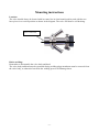
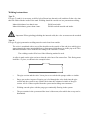
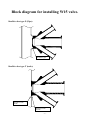
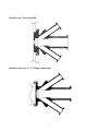
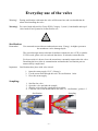
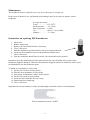
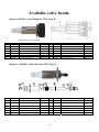
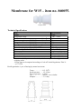
MN-000000 User manual for W15 valve
User manual
for W15
sampling valve
Contents:
Contents: ...........................................................................................................................................1
Introduction: .....................................................................................................................................2
Presentation: .....................................................................................................................................2
Restrictions:...................................................................................................................................2
Valve function ...............................................................................................................................2
W15 Item no.: 860001 and 860009.....................................................................................................3
Mounting instructions ..........................................................................................................................4
Location:........................................................................................................................................4
Before welding: .............................................................................................................................4
Welding instructions:........................................................................................................................5
Type T: ..........................................................................................................................................5
Type P: ..........................................................................................................................................5
Block diagram for installing W15 valve. .............................................................................................6
Keofitt valve type P (Pipe): ..............................................................................................................6
Keofitt valve type T (tank): ..............................................................................................................6
Keofitt valve Varivent Ø68: .............................................................................................................7
Keofitt valve type C, 3” Clamp connection:.....................................................................................7
Everyday use of the valve ....................................................................................................................8
Sterilisation:......................................................................................................................................8
Sampling:..........................................................................................................................................8
Maintenance:.....................................................................................................................................9
Instructions on replacing PTFE membrane: .....................................................................................9
Available valve heads: .......................................................................................................................10
Item no. 865541 - Valve Head for W15 Type H ............................................................................10
Item no.: 865544 - Valve Head for W15 Type N ..........................................................................10
Membrane for W15 – item no. 860055..............................................................................................11
Technical Specification: .................................................................................................................11
-1-
Introduction:
Manufacturer:
Keofitt a/s,
Hans Egedes Vej 19
5210 Odense NV
Denmark
Sampling valve, Type:
Year of production:
W15
2002
Presentation:
The Keofitt sampling valve is a valve which can be readily sterilised and which meets both hygienic
and production requirements. This means that an effective cleaning and sterilisation of the sampling
valve can be carried out between random samples independently of the course of the production
process.
The Keofitt W15 valve is 3-A certified. 3-A Sanitary Standard is an American standard which is
normative for a component’s ease of cleaning and sterilisation. The standard ensures optimum
conditions for food products which may come into contact with the component in question.
The valve is used in a wide range of business areas where sampling high viscosity products, such as
dairies, yogurt, fruit and marmalade industries.
Warning! During sterilisation with steam the valve will become hot, and care should thus be taken
when handling the valve.
Restrictions:
•
•
•
•
•
The valve cannot be used for vacuum since the membrane will be sucked hard into the seat.
The W15 and W25 valves are only available with PTFE membranes.
The PTFE membrane resists most CIP fluids and very high steam temperatures.
W15 is only available with Clamp on the inlet /outlet connections.
For best results it is best to leave the steam hose constantly connected to the valve. Detaching
the hose risks air contamination and makes the sterilisation process unnecessarily complicated.
Valve function
The valve is designed to regularly take representative random samples in the production process.
The valve is therefore designed such that effective cleaning, sterilisation and sampling can be
carried out regularly without interrupting the production process.
Sterilisation is carried out by supplying steam through the upper of the valve’s two hose pieces. It is
the perfect, hygienic design in the inner part of the valve which enables absolute sterilisation in a
closed state.
Note!
The membrane functions both as a dynamic packing in the valve seat and as a hygienic,
static packing against the valve body.
-2-
W15 Item no.: 860001, 860003, 860009 and 860011
Valve body W 15, Varivent Ø68
Item no.: 860009
Valve body W 15 Type H
Item no.: 860001
Valve body W 15 Type C
Item no.: 860003
Valve body W 15 Type P
Item no.: 860011
Welding:
Port Connection:
Use for:
Material:
Inner surface:
How to use:
Max. Working pressure:
Outlet diameter:
Net weight:
available for tank or pipe.
Varivent ø68mm and 3” clamp connection.
Sample marmalade, yoghurt and fruit products and other
high viscosity products.
AISI 316L (1,4404)
Ra 0,8m
Manually or pneumatically operated.
0 - 6 bar (g)
15mm
1,70 kg./pc. 860001 and 1,80 kg./pc 860009.
3A certificate
-3-
Mounting instructions
Location:
The valve should always be located with its centre line in a horizontal position, and with the two
hose pieces in a vertical position as shown in the diagram. The valve will then be self-draining.
Valve s centre line
Before welding:
Remember to disassemble the valve body and head.
The valve body and head must be separated during welding plugs membrane must be removed from
the valve body, as otherwise heat from the welding process will damage them.
-4-
Welding instructions:
Type T:
For type T (tank) it is necessary to drill a hole ø50 mm into the tank wall, and then fit the valve into
this hole flush with the inside of the tank. Welding should be carried out as a penetration welding.
Material thickness less than 4 mm:
Material thickness greater than 4 mm:
Weld from inside.
Weld from both outside and inside.
Important! When grinding/polishing the internal weld, the valve seat must not be touched.
Type P:
For type P (pipe) penetration welding must be carried out from outside.
The valve is machined with a recess-like shoulder on the outside of the end piece which gives
approximately the same material thickness (2mm material thickness) as in the pipe wall. This
machined shoulder can be modified according to the customer’s wishes.
The welding result will be best if the following method is used:
A collar is made on the pipe section so that the valve has a flat contact face. This flaring must
look like a T-piece, as shown in the example below.
•
The pipe section and the valve’s hose pieces are sealed with sponge rubber or similar.
•
Purge gas such as Argon or Formier gas is fed through the valve body into the pipe
section and the system is now filled with 6 times the estimated volume of the pipe
section. All O2 is thus expelled from the system and welding can commence.
•
Welding can take place with the purge gas continually flowing in the system.
•
The gas remains in the system until the item is lukewarm, after which the set-up can be
dismantled.
-5-
Block diagram for installing W15 valve.
Keofitt valve type P (Pipe):
Welded to pipe
Keofitt valve type T (tank):
Welded to Tank
inside
Welded to Tank
Outside
-6-
Keofitt valve Varivent Ø68:
Keofitt valve type C, 3” Clamp connection:
-7-
Everyday use of the valve
Warning!
During sterilisation with steam the valve will become hot, and care should thus be
taken when handling the valve.
Warning!: For valve heads allowed for Group IIGD, Category 2 (zone 1) both handle and top of
valve heads N and Q must be cleaned before use.
Sterilisation:
Remember!
Use saturated steam without condensation at max. 2 bar(g). At higher pressures
the membrane can be damaged/split.
The coaxial design ensures absolute cleanliness without the use of CIP or similar.
If CIP is used, please refer to enclosed data sheet. If in doubt, contact Keofitt.
For best results it is best to leave the steam hose constantly connected to the valve.
Detaching the hose risks air contamination and makes the sterilisation process
unnecessarily complicated.
Important:
Sterilisation takes place with valve closed.
1. Open the steam supply 121°C (2 bar(g)).
2. Let the steam flow through the valve for sterilisation. 1 min.
3. Close the steam supply.
Sampling:
1.
2.
3.
4.
Sterilise the valve.
Open the valve and take the sample.
Shut the valve after the sample has been taken.
Clean the valve with steam and/or hot water, cf. ’sterilisation’, points 1-3.
Sterilisation
Sampling
-8-
Maintenance:
The membrane must be replaced once every year with terms of average use.
In the event of intensive use, sterilisation and cleaning it may be necessary to replace it more
frequently.
Average use means:
Temp……………..115-1300C
Steam pressure……1,5-2,5 bar
Process pressure….1-6 bar
Cip………………..Nho4 < 3% or similar
Samples…………...1-5 a day
Instructions on replacing PTFE membrane:
1.
2.
3.
4.
5.
6.
7.
8.
Open valve.
Release clamp ring.
Remove the valve head from the valve body.
Close valve head.
Push the membrane upwards until it is stuck in compressed mode.
Insert tool for membrane, between the membrane and the valve.
Close valve head.
Now the membrane should loose from the valve head and can be replaced.
Important: Once the membrane has been removed from the valve head the click system in the
membrane might be damaged. Therefore the membrane might be unsafe for further use and it is not
recommended to use the membrane again.
To attach new membrane to valve head.
9. Set the valve head to closed position.
10. Place the new membrane on valve head.
11. Press down on membrane, until it clicks in place.
12. Set the valve head in open position.
13. Insert the valve head into the valve body.
14. Attach and close clamp ring.
15. Close valve head.
Important: Do not use hammer or other tool that might scratch the surface of the membrane.
Tool for membrane item no. 300255
-9-
Available valve heads:
Item no. 865541 - Valve Head for W15 Type H
Spare parts list for 865541:
Nr
1
2
3
4
5
6
7
Part Nr.
860349
860241
860130
860149
509004
860410
860140
Part name
Pressure Disc for W15
Thread for handle W15
Spring seat for W15
Bushing for valve body W15
Screw for W15
Spring for W15 Head type H
Stem for W15 valve
material
AISI 304
AISI 304
AISI 304
AISI 304
St. St.
St. St.
AISI 304
Nr
8
9
10
11
12
13
14
Part Nr.
860341
860359
860441
860459
860055
900186
600243
Part name
Handle for W15 valve head
Disc for stop
Cover for handle W15
Disc for top
Membrane
Clamp ring
Pin for Q-handle.
material
Pom-C
AISI 304
AISI 304
AISI 304
PTFE
St. St.
AISI 304
material
NBR
Carbon
PTFE
NBR
AISI 304
Misc.
Silicone
Item no.: 865544 - Valve Head for W15 Type N
Nr
1
2
Part Nr.
860055
860144
Part name
Membrane
Cylinder for W15
material
PTFE
AISI 304
Nr
7
8
Part Nr.
850821
850822
Part name
Scrape ring Ø10x16,1x6
Glider
3
4
5
6
860145
860146
860349
860410
Stem for W15
Cap for W15
Pressure Disc for W15
Spring for W15 Head type H
AISI 304
AISI 304
AISI 304
St. St.
9
10
11
12
850824
900186
860840
860051
Stamp ring Ø30x22x3,25
Clamp ring for W15
Swivel for air cylinder
Pressure disc
- 10 -
Membrane for W15 – item no. 860055.
Length 51mm
Technical Specification:
Type:
AF1012 PTFE
Colour
White
Temperature range
- 200 - +200ºC
Ball hardness
N/mm2
29
2
Tensile strength
DIN53455
N/mm
35
Elongation at break DIN53455
%
350
Density
DIN 53479
g/cm3
2.17
Shore D
DIN 53505
57
Thermal conductivity W/m.k DIN 57572
0.25-0.5
Expansion Coefficient DIN 52612
9-12x10-5 K-1
Friction coefficient
very low (<0.1)
Flammability
Inflammable UL 94VO
Chemical resistance
*
Food safe
Yes (FDA**)
* Is not attacked by common chemicals, with the exception of strongly
oxidising acids.
**FDA approved compound according to Code of Federal Regulations Title 21
- § 177.1550
Keofitt guaranties 1 year of lasting by normal use means.
Temp……………..115-1300C
Steam pressure……1,5-2,5 bar
Process pressure….1-6 bar
Cip………………..Nho4 < 3% or similar
Samples…………...1-5 a day
- 11 -
For complete set of updated data sheets for all W15 valve bodies and heads please refer to our web
page www.keofitt.dk
- 12 -