1
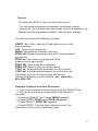
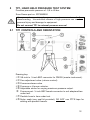
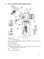
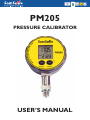
PM205
PRESSURE CALIBRATOR
USER’S MANUAL
Thank you for purchasing our pressure meter.
This product is manufactured in accordance with our strict standards for
quality in design, components, and workmanship to fulfill our vision:
“To be the leading company in high quality self-contained
products”
Scan-Sense AS reserves the right to make improvements or alterations
to their products without incurring any responsibility to make the same
improvements or alterations to products previously sold.
© Scan-Sense AS.
All rights reserved. No part of this publications may be reproduced,
stored in a retrieval system, or transmitted in any form by any means,
electronic, mechanical, photocopying, recording, or otherwise without
the prior permission of Scan-Sense AS.
All efforts have been made to ensure the accuracy of this handbook.
We at Scan-Sense AS are always striving to improve our products and
handbooks, therefore we would greatly appreciate being informed of
any errors found in our product or its handbook.
The above
notwithstanding, Scan-Sense AS can assume no responsibility for any
errors in this handbook or the consequences.
Symbol used to identify an action that can cause personal
injury or damage to equipment.
Always release internal pressure at connectors before
disconnecting.
Uncontrolled release of high pressure can result in
personal injury and damage to equipment.
Scan-Sense AS
Bekkeveien 163
N-3173 Vear,
Norway
Phone:
+ 47 33 36 30 00
Fax:
+ 47 33 36 30 01
Email: [email protected]
www.scansense.no
Table of Contents
1
1.1
1.2
1.3
1.4
1.5
1.6
DESCRIPTION OF THE PM205………………………………………. 1
CALIBRATION LABEL………………………………………………..... 1
CERTIFICATION………………………………………………………... 1
WARRANTY…………………………………………………………….. 2
CONVENTIONS USED IN THIS DOCUMENT……………………… 2
BATTERY CHANGE/ BATTERY LIFE……………………………… 2
PM205 NOT OPERATING/ FAILED ……………………………….. 3
2
2.1
2.2
2.3
2.4
CONTROLS AND INDICATORS………………………………………4
DISPLAY, CONTROLS AND CONNECTIONS……………………… 5
MEASURING PROCEDURE OF THE PEAK-MODE………………. 7
INSTALLATION…………………………………………………………. 7
RANGES/ CALIBRATION ……………………………………………... 7
3
SPECIFICATION OF PM205………………………………………….. 8
4
4.1
4.2
4.3
LTP1, LOW PRESSURE HAND PUMP……………………………....9
LTP1, CONTROLS AND ORIENTATION……………………………..9
OPERATION OF THE LPT1…………………………………………… 10
LTP1 FAULT INVESTIGATION……………………………………….. 11
5
5.1
5.2
5.3
TP1, HAND HELD PRESSURE TEST SYSTEM………………........ 12
TP1 CONTROLS AND ORIENTATION………………………………. 12
OPERATION OF THE TP1…………………………………………….. 13
TP1 FAULT INVESTIGATION………………………………………….14
6
6.1
6.2
HTP1, HYDRAULIC HAND HELD PRESSURE TEST SYSTEM…. 15
HTP1 CONTROLS AND ORIENTATION…………………………….. 16
OPERATIONS OF THE HTP1………………………………………….16
7
7.1
7.2
7.3
7.4
PV411 PNEUMATIC/HYDRAULIC HAND-PUMP SYSTEM………. 18
PV411 CONTROLS AND ORIENTATION………………………….... 19
PV411 PNEUMATIC OPERATION………………………………….... 20
PV411 HYDRAULIC OPERATION………………………….………… 22
PV411 FAULT INVESTIGATION……………………………..………..25
8
PM205 ACCESSORIES……………………………………………….. 26
9
CERTIFICATES………………………………………………………… 28
i
1
DESCRIPTION OF THE PM205
The PM205 Pressure Calibrator has been designed as a self-contained,
portable pressure meters that have been calibrated to precision
pressure equipment traceable to national standards.
Each unit is marked with:
• Calibration label, next calibration date
• Serial number
• Production year
• Pressure range.
1.1
CALIBRATION LABEL
Scan-Sense AS certifies that this product meets published
specifications at the time of shipment from the factory. Scan-Sense AS
further certifies that its calibration measurements are traceable to
accredited international standards. Each pressure calibrator has a
calibrated label showing the last date of calibration and the date when
the next calibration is due. Calibration is scheduled annually, unless
you believe the unit to be defective, whereupon the unit will be
calibrated after repair and receive a new label showing the date
calibrated and the new calibration-due date. Check the calibrated label
to ensure the Pressure Meter Calibrator has a valid calibration date
before using the unit. Calibration must be done by Scan-Sense AS
or a certified supplier/service center.
1.2
CERTIFICATION
Scan-Sense AS certifies that the PM205 complies with its published list
of specifications at the time it was manufactured. Scan-Sense AS also
certifies that its calibration measurements are traceable to Norwegian
Accreditation and to the calibration facilities of other International
Standards Organization (ISO) members. Scan-Sense AS confirms that
the PM205 complies with the following standards:
Electromagnetic compatibility as established in the
guidelines of the European Community, EMC
89/336/EWG . The following norms are applied:
EN 61000-6-2, EN 61000-6-3.
1.3
WARRANTY
This product is guaranteed free from defects in material and
workmanship for one (1) year from the date of shipment. During this
1
warranty period, Scan-Sense AS will, at its option, either repair or
replace the PM205 should it prove to be defective. The product must be
returned to a service facility designated by Scan-Sense AS for warranty
service or repair. The foregoing warranty will not apply to defects
resulting from improper maintenance by the purchaser, purchasersupplied software or interfacing, unauthorized modification or misuse,
operation exceeding the environmental specifications for the PM205, or
improper site preparation. No other warranty is expressed or implied by
Scan-Sense AS, and Scan-Sense AS shall not be liable for any direct,
indirect, special, incidental or consequential damages, whether based
on contract, tort, or any other legal theory.
1.4
CONVENTIONS USED IN THIS DOCUMENT
We have provided this section of the Handbook to help you identify
noteworthy symbols, terms and conventions used in this handbook.
Look for the following:
Symbol used to
identify an action that
can cause personal
injury or damage to
equipment.
Conformité
Européenne
1.5
Terms and definitions:
We define calibration as being
able to compare the ability of
the equipment to perform to a
known standard. Pressure
calibration provides a means of
quantifying uncertainties in
pressure measurement in order
to optimize sensor and/or
system accuracy.
BATTERY CHANGE/ BATTERY LIFE
When the battery starts weakening, a low battery warning (BAT LOW)
will appear in the upper left corner of the display.
Battery change: Open the instrument (turn the display ring beyond the
limit stop). Open the battery compartment and change the battery (type
CR2430). Make sure that the O-ring remains embedded in the cover.
The battery life is 150 hours in Peak-mode (at continous operation) and
1000 hours in normal measuring mode.
*
2
1.6
PM205 NOT OPERATING/FAILED
Repairs must be done by manufacturer or supplier certified for
service/repair.
Replacement parts must be obtained from the
manufacturer.
Manufacturers address:
Phone: + 47 33 36 30 00
Scan-Sense AS
Fax:
+ 47 33 36 30 01
Bekkeveien 163
Email: [email protected]
N-3173 Vear, Norway
3
2
CONTROLS AND INDICATORS
2.1
DISPLAY, CONTROLS AND CONNECTIONS
The PM205 has two operating keys. The left key (SELECT) serves to
select the functions and the pressure units. The right key (ENTER)
activates the selected function or pressure unit. The right key is also
used to switch between the MAX.- and MIN.-value in both the Manoand Peak-mode.
4
Turn-on:
Pressing the SELECT key turns the instrument on.
The instrument subsequently displays the software version
(year/week), the full-scale pressure range, the actual pressure (top
display) and the last measured MAX.-value (bottom display).
The instrument has the following functions:
RESET: Max.-/Min.-value and Peak-value are set to the
actual pressure
OFF: Turns off the instrument
MANO: Releases the following functions:
PEAK off: Normal measuring mode with 2 measurements
per second
PEAK on: Fast measuring mode with 5000
measurements per second
ZERO SEt: Sets a new Zero reference
ZERO rES: Sets the Zero to factory setting
CONT on: Deactivates the automatic turn-off function
CONT off: Activates the automatic turn-off function (the
instrument turns off 15 minutes after the last key
function)followed by the unit selection: bar, mbar/hPa,
kPa, MPa, PSI
Example: Setting a new Zero Reference:
--> Turn on the instrument by shortly pressing the SELECT-key.
--> Wait for the instrument’s measuring mode (approx. 3
seconds).
--> Press the SELECT-key 3 times: MANO appears.
--> Press ENTER: PEAK on or PEAK off appears.
--> Press SELECT: ZERO SEt appears.
--> Press ENTER: The new Zero reference is set. The
instrument returns to the measuring mode.
5
Display of the Minimum Pressure Value
When in the measuring mode (Display: Actual Pressure and Max.value), you may display the Min.-value for 5 seconds by shortly pres
sing the ENTER-key.
Notes:
1) The functions and units can also be called up by
keeping the SELECT-key depressed. Releasing the key
enables the displayed function or unit to be activated with
the ENTER-key.
2) If the selected function or unit is not activated within 5
seconds with the ENTER-key, PM205 returns to the
measuring mode without changing any settings.
3) Turning PM205 on and off does not influence any of
the previous settings.
4) If the PEAK on or CONT on function is activated, it is
indicated with a flashing sign on the display.
5) If a pressure can not be represented on the display,
OFL (overflow) or UFL (underflow) appears on the
display.
6) If the actual pressure goes beyond the measuring
range, the last valid pressure value starts flashing on the
display.
2.2
MEASURING PROCEDURE OF THE PEAK-MODE
6
2.3
INSTALLATION
Ref. A) Screw the G “ male port of PM205 into the choosen pressure
pump and tighten using the lower hexagon of the transducer. Loosen
the upper hexagon and rotate the PM205 to the desired position. Retighten. Ref. Chapter 4 to 7 for further details.
Ref. B) The face of the PM205 can be rotated trough 355 Degrees.
This feature allows the PM205 to be mounted in all possible positions;
vertical, horizontal or upside down.
2.4
RANGES/ CALIBRATION
The factory setting of the Zero for the ranges -1…3 bar or -1…30 bar is at 0
bar absolute. For sealed gauge pressure measurements, activate “Zero Set”
at ambient pressure. Instruments with ranges >30 bar are calibrated in a
sealed gauge mode at ambient pressure.
7
3
SPECIFICATIONS OF PM205
Pressure Ranges, Resolution, Overpressure:
Range
Resolution
Overpressure
-1 to 3 bar
1mbar
10 bar
-1 to 30 bar
10 mbar
60 bar
0 to 60 bar
10 mbar
120 bar
0 to 300 bar
100 mbar
400 bar
0 to 700 bar
200 mbar
700 bar
0 to 1000 bar
200 mbar
1000 bar
Readings per second
Zero function
Peak function
Auto power off
Power supply
Battery life
5000 (PEAK mode)
Yes
Max. or Min.
15 min.
Battery
1000 hours continous operation
MANO-Mode
150 hours of continous operation in
PEAK-Mode
Litium battery
3.0V size CR2430
Display
LCD
Selectable read out
bar, mbar/hPa, kPa, MPa,
PSI, kp/cm2
Standard process coupling
” BSP MALE, Swivel
Protection class (EN 60529)
IP65
Dimentions
118mm (h) x 42mm (d), ø76mm (w)
Weight
0,21 kg
Accuracy RT (room temperature) *
< 0,1 %FS
Total Error Band (0 to 50 °C)
< 0,2 % FS
Storage-/ Operating Temperature -20 to 70 °C / 0 to 50 °C
Compensated Temperature Range 0 to 50 °C
8
4
LTP1, LOW PRESSURE HAND PUMP
Provides low pressure of -0,9 to 3 bar.
Scan-Sense part no. 3PPM02050
Always release the internal pressure at the connectors before
disconnecting. Uncontrolled release of high pressure can result in
personal injury and damage to equipment.
Do not connect LTP1 to external pressure source!
4.1
LTP1 CONTROLS AND ORIENTATION
Drawing key:
Pressure-release valve.
Fine-adjustment control.
Pressure or Vacuum selector.
Two push-fit connectors to accept 4mm OD hoses to item
under test and PM205 (master instrument).
Pressure port: -inch BSP female connector to suit adapters/item
under test.
Pump handle.
Nylon seals (see seal kit provided). DO NOT use PTFE tape for
sealing with parallel threads.
Pressure-relief valve.
9
RELEASE VALVE Can be used to reduce or release pressure in
the system. The rate of pressure reduction is dependent upon the
degree of rotation when operating the valve. Minimal force is required
to seal the system.
FINE-ADJUSTMENT CONTROL The generated pressure can
be fine adjusted by turning the fine-adjustment valve either in or out to
increase or decrease the pressure.
IMPORTANT
Do not wind the fine-adjustment valve any further when the
top of the pump body is visible.
PRESSURE/VACUUM SELECTION Press the selector
as indicated on the label to engage the desired mode. Ensure that
the release valve is fully closed (clockwise motion) prior to
pumping.
PRESSURE PORTS The hoses are fitted by pushing
them into the connectors until resistance is felt. To remove the
hoses, press the collar “in” on the connector while pulling on the hose.
PRESSURE RELIEF VALVE The maximum output pressure can be set
using the pressure relief valve located
inside the main piston, and is accessed via
the handle-retaining “Grub Screw”.
If the system has not been used for a period of time, it may be difficult
to operate on the first stroke.
Seal replacement: Depending on the frequency of use, the main piston
seal (and others) may need replacing. Replacement seals and
instructions for fitting are contained in the seal kit (LTPK1).
4.2
OPERATION OF THE LTP1.
Refer to the orientation drawing to locate the controls.
1. Choose the correct adapters and seals and connect to the
pressure port at one end of the flexible hoses .
2. Choose the correct adapters and seals and connect the item under
test to the pressure port at the end of the second flexible hose Ensure seals are fitted and adapters tightened to a maximum
torque of 15Nm.
3. Screw the fine-adjustment valve fully clockwise.
10
4.
5.
6.
7.
8.
Screw the fine-adjustment valve counter-clockwise 4 to 6 full
turns.
Screw the pressure-release valve fully clockwise, tightening to
ensure a good seal.
Using a small screwdriver, adjust the pressure-relief valve to
set the desired maximum output pressure. Turn the “Grub Screw”
located in the main piston clockwise to increase or counterclockwise to decrease the pressure setting.
Operate the handle until the pressure is close to that which is
finally required.
Wind the fine-adjustment valve “in” to increase pressure or
“out” to decrease pressure until the required pressure is reached.
After increasing the pressure, it may take up to 30 seconds for the
pressure to settle due to thermodynamic effects, setting of seals or
expansion of the flexible hose.
STOP unscrewing the fine-adjustment valve when the top of the pump body becomes visible!
9.
Reductions in pressure can also be achieved by careful use of the
pressure-release valve .
10. Vacuum is achieved using the above procedure and having the
changeover valve pushed completely towards the vacuum
position.
11. End of operation procedure.
4.3
LTP1 FAULT INVESTIGATION
In the event that the system appears to lose pressure, check the
connections to ensure that they are tight and the seals are good.
Replace poor seals and repeat the operation. When testing for leaks
you may notice that air is drawn in or expelled from around the
changeover valve , this is normal and should not be a cause for
concern.
Connection to the handheld test system is sealed with “o”-ring or
bonded seals and should not leak. The pipe or body connection can be
checked but should not be tightened more than 2 Nm.
DO NOT attempt to tighten the other fittings to the test system as this
can cause damage to the sealed joints!
11
5
TP1, HAND HELD PRESSURE TEST SYSTEM
Provides pneumatic pressure of -0,8 to 40 bar.
Scan-Sense part no. 3PPM40050
Always release internal pressure at connectors before
disconnecting. Uncontrolled release of high pressure can result in
personal injury and damage to equipment.
Do not connect TP1 to external pressure source!
5.1
TP1 CONTROLS AND ORIENTATION
Drawing key:
3/8-inch to -inch BSP connector for PM205 (master instrument).
Fine-adjustment valve (volume control).
Pressure-release valve
Pressure or Vacuum selector.
Adjustable stroke for varying maximum pressure output.
Pressure port: -inch BSP female connector to suit adapters/item
under test.
Flexible hose to item under test.
Nylon seals (see seal kit provided). DO NOT use PTFE tape for
sealing with parallel threads.
12
RELEASE VALVE Can be used to reduce or release pressure in
the system. The rate of pressure reduction is dependent upon the
degree of rotation when operating the valve. Minimal force is required
to seal the system.
VOLUME CONTROL The generated pressure can be fineadjusted by turning the fine-adjustment valve either clockwise or
counter-clockwise to increase or decrease the pressure accordingly.
IMPORTANT
Under no circumstances should the fine-adjust
valve be wound back beyond the read-line
indicator on the body. Should this occur, then the
pressure must be released from the system before
attempting to re-engage the fine-adjustment valve.
OVER PRESSURE PROTECTION To adjust the maximum
output pressure of the system, turn the nuts to increase or decrease the
stroke length.
PRESSURE/VACUUM SELECTION Press the selector
as indicated on the label to engage the desired mode. Ensure that
the release valve is fully closed (use a clockwise motion) prior to
pumping.
If the system has not been used for a period of time, it may be difficult
to operate on the first stroke. The cylinder has been lightly greased at
assembly, but if additional lubrication is ever required, apply a minimal
amount to the inside of the cylinder. Access is via the three retaining
screws located under the black collar.
Seal replacement: Depending on the frequency of use, the main piston
seal (and others) may need replacing. Replacement seals and
instructions for fitting are contained in the seal kit (TPK1).
5.2
OPERATION OF THE TP1
Refer to the orientation drawing to locate the controls.
1. Choose the correct adapters and seals and connect item under
test to pressure port at the end of the flexible hose .
Ensure seals are fitted and adapters tightened to a maximum
torque of 15Nm.
2. Screw the fine-adjustment valve fully clockwise.
3. Screw the fine-adjustment valve counter-clockwise 4 to 6 full
turns.
13
4.
5.
6.
Screw the pressure-release valve fully clockwise, tightening to
ensure a good seal.
Operate handles until the pressure is close to that which is finally
required. Ensure handles are fully squeezed together on each
stroke to achieve maximum pressure output.
Wind the fine-adjustment valve (clockwise to increase
pressure or counter-clockwise to decrease pressure) until the
required pressure is reached. After increasing the pressure, it may
take up to 1 minute for the pressure to settle due to
thermodynamic effects, setting of seals or expansion of the flexible
hose.
NEVER screw the fine-adjustment valve beyond
the red line indicator!
7.
8.
9.
5.3
Reductions in pressure can also be achieved by careful use of the
pressure release valve .
Vacuum is achieved using the above procedure and having the
changeover valve pushed completely towards the vacuum
position.
End of operation procedure.
TP1 FAULT INVESTIGATION
In event that the system appears to lose pressure, check the
connections to ensure they are tight and the seals are good. Replace
poor seals and repeat the operation. When testing for leaks you may
be notice that air is drawn in or expelled from around the changeover
valve , this is normal and should not be a cause for concern
Connection to the handheld test system is sealed with “o”-ring or
bonded seals and should not leak. The pipe or body connection can be
checked but should not be tightened more than 2 Nm.
DO NOT attempt to tighten the other fittings to the test system as this
can cause damage to the sealed joints!
14
6
HTP1, HYDRAULIC HAND HELD PRESSURE TEST
SYSTEM
Provides hydraulic pressure of 0 to 700 bar
Scan-Sense part no. 3PPM70150
Always release the internal pressure at the connectors before
disconnecting. Uncontrolled release of high pressure can result in
personal injury and damage to equipment. Excessive pressure can
crack or break the fluid reservoir case!
Reservoir fluid level: If the fluid level in the reservoir falls considerably
during use, a partial vacuum may be created in the reservoir that can
affect the performance of the pump. To avoid this, simply allow air to
enter the reservoir by partly unscrewing the filling plug.
Seal replacement: Depending on the frequency of use, the main piston
seal (and others) may need replacing. Replacement seals and
instructions for fitting are contained in the seal kit (HTPK1).
6.1
HPT1 CONTROLS AND ORIENTATION
Drawing key:
3/8-inch to -inch BSP connector for PM205 (master
instrument).
15
Pressure-release valve.
Fine control
Pressure port: M16 x 1.5 mm quick connector for flexible hose to
switch adapters or item under test.
100cc reservoir. Fluid level to maximum fill marker.
Reserve-filling plug.
Prime/High pressure selector.
Fluid-inlet tube.
Rear port: for Pressure Relief Valve ONLY. DO NOT use for any
other purpose.
6.2
OPERATION OF THE HTP1
Refer to the orientation drawing to locate the controls.
1. Remove the filling plug and fill the reservoir to 6mm level
with the recommended fluid and replace the filling plug.
2. Connect the instrument under test to the flexible hose/gauge
adapter and attach to the pump via the quick-fit connection .
3. Adjust the fine control to mid-travel.
4. Ensure that the pressure-release valve is open (turn fully
clockwise, then one turn counter-clockwise). Fully squeeze the
handles “in” and turn the selector to the “prime” position.
5. Operate the handles several times to expel air from the pump
(ensure that the fluid-inlet tube remains immersed in fluid at all
times).
6. Close the release valve fully clockwise.
7. Prime the system by squeezing the handles together and then
releasing them, to allow the oil to enter the pump cylinder. Repeat
as necessary until the system is fully primed and low pressure is
indicated on either the master or test instrument.
8. With the handles fully squeezed “in” select the “high” pressure
position on the selector and operate the handles to generate
approximate pressure. Note: Smaller handle strokes enable
easier pressure generation at high pressures.
9. Adjust pressure to the required value using the fine control .
Note that the pressure will fall slightly, immediately after pressure
generation due to the thermodynamic effect but will stabilize after a
short time.
DO NOT EXCEED the maximum operating pressure indicated
on the pump label! Fluid reservoir can crack or break if excess
pressure applied.
16
10. To totally release pressure from the system, turn the release valve
one turn counterclockwise and select the “prime” position on the
selector after first squeezing the handles fully “in”. Note:
Careful use of the release valve and fine control enables a
controlled release of pressure, essential for calibration purposes.
11. End of operation procedure.
17
7
PV411 PNEUMATIC/HYDRAULIC HAND-PUMP SYSTEM
Pressure ranges (maximum safe working pressure is 700 bar):
•
•
•
Provides pneumatic pressure of 0 to 60 bar
0 to –0.95 bar (near vacuum)
Scan-Sense part no. 5PV-411
Provides hydraulic pressure of 0 to 700 bar
Scan-Sense part no. 5PV-411-115
Always release the internal pressure at the connectors before
disconnecting. Uncontrolled release of high pressure can result in
personal injury and damage to the equipment.
Reservoir-fluid level: If the fluid level in the reservoir falls considerably
during use, a partial vacuum may be created in the reservoir that can
affect the performance of the pump. To avoid this, simply allow air to
enter the reservoir by partly unscrewing the filling plug. Hydraulic fluids
must be compatible with stainless steel, anodized aluminum, nitrile
rubber, PTFE, polypropylene, delrin, acrylic and nylon. Hydraulic fluid
must have a maximum viscosity of 150 cSt at 40°C. Other fluids that
can be used are de-mineralized water or mineral-based oils (SAE 40W,
ISO viscosity grade 150).
Seal replacement: Depending on frequency of use, the main piston
seal (and others) may need replacing. Replacement seals and
instructions for fitting are contained in the seal kit (PV411K1).
18
7.1
PV411 CONTROLS AND ORIENTATION
PV411, drawing key 1
Drawing key 1:
Inlet (reservoir) port
-inch to -inch BSP connector for PM305 (master instrument)
Volume adjuster
Limit adjuster
Scissor-action handles
Pressure port: M16 x 1.5 mm quick connector for flexible hose to
suit adapters and item under test.
Selector valve
Pressure-relief valve
19
7.2
7.2.1
PV411 PNEUMATIC OPERATION
Pneumatic-selector valve and scissor-action handles limitadjuster of the PV411
Selector valve Pressure
Turn the selector valve fully clockwise
(“in”) position.
Vacuum
Turn the selector valve fully counterclockwise (“out”) position.
Vent
Slowly turn the selector valve to the
center position.
Scissor-action handles limit-adjuster
Turning the limit adjuster clockwise reduces the stroke of the
scissor-action handles . Turning the limit adjuster counter-clockwise increases the stroke.
For maximum pneumatic pressure generation, turn the limit adjuster
fully counter-clockwise.
7.2.2
Pneumatic Operation of the PV411
As a pneumatic pump, selector valve vents the system to
atmosphere, between selection of pressure and vacuum. Operating the
scissor-action handles provides the pumping stroke for generating
pressure. A volume adjuster allows small adjustments of the
system pressure.
In pressure mode, air/fluid is drawn through the inlet port on top of
the pump and forced out through the two outlet ports ( and ). In
vacuum mode, the air/fluid flow is reversed as air/fluid is drawn in
through the top and rear outlet ports ( and ) and expelled
through the inlet port .
Volume adjuster
20
Low pressure__ With the selector valve set to vent (“open”), turn
the volume adjuster fully counter-clockwise to the
“out” position. Turn the selector valve fully clockwise
to the “in” position to select pressure. Turn the volume
adjuster clockwise to generate pressure.
High pressure _ Turn the volume adjuster to the mid-position. In
this position, fine adjustments of the generated
pressure can be made. Using the scissor-action
handles , generate the approximate pressure;
then turn the volume adjuster clockwise to the “in”
position to increase the pressure or turn the volume
adjuster counter-clockwise to the “out” position to
decrease the pressure.
Vacuum ______ Turn the selector valve fully counter-clockwise to
the “out” position. Turn the volume adjuster to the
mid-position. In this position, fine adjustments of the
generated vacuum can be made. Using the scissoraction handles , generate the approximate
pressure; then turn the volume adjuster clockwise
to the “in” position to increase the pressure or turn the
volume adjuster counter-clockwise to the “out”
position to decrease the pressure.
Refer to the orientation drawing to locate the controls.
Pressure
1. Connect the PV411 to the item under test using the hoses, pipes
and adapters.
2. Turn the selector valve fully clockwise to the “in” position.
3. Operate the scissor-action handles to generate the
approximate pressure, allowing time for thermal stabilization.
4. If necessary, use the volume adjuster to adjust to the required
pressure.
5. After attaining the required pressure, operate the scissor-action
handles to generate a higher pressure. Alternatively, vent
pressure to atmosphere by slowly turning the selector valve counter-clockwise to the center position.
6. End of procedure. Depressurize the pump and disconnect from
the pipes and equipment.
Vacuum
1. Connect the PV411 to the item under test using the hoses, pipes
and adapters.
21
2.
Turn the selector valve fully counter-clockwise to the “out”
position.
3. Operate the scissor-action handles to generate the
approximate vacuum, allowing time for thermal stabilization.
4. If necessary, use the volume adjuster to adjust to the required
vacuum.
5. After attaining the required vacuum, operate the scissor-action
handles to generate more vacuum. Alternatively, vent vacuum
to atmosphere by slowly turning the selector valve counterclockwise to the center position.
6. End of procedure. Depressurize the pump and disconnect.
7.3
PV411 HYDRAULIC OPERATION
7.3.1
Setting pressure relief valve of the PV411
The pressure relief valve (PRV) can be set at pressures from 30 to 700
bar.
Do not exceed 700 bar as this can damage the internal seals of
the PRV and the PV411
If the system pressure exceeds the set pressure, the PRV opens and
vents fluid through the inlet port to the reservoir. When system
pressure decreases below the set pressure, the PRV closes.
Drawing key 3:
PRV locking screw (quantity 2).
PRV locknut (with left-hand thread).
PRV adjusting nut (with left-hand thread)
PRV, drawing key 3
Refer to the orientation drawing PRV411 drawing key 1 and PRV
drawing key 3 to locate the controls.
1. Connect a suitable pressure indicator to either outlet port or
(see PRV411, drawing key 1). Fit a blank to the unused port.
2. Squeeze the scissor-handles together to increase pressure
until the relief valve operates.
3. Loosen the two PRV locking screws .
4. Loosen the locking nut by turning it clockwise.
5. Set the relief pressure by turning the PRV adjusting nut .
Turn counter-clockwise to increase pressure.
Turn clockwise to decrease pressure.
6. After setting the PRV, hold the adjusting nut in position and
tighten the locking nut . Remember that the locking nut has a
left-hand thread.
7. Check operation of the PRV. If necessary, reset the PRV.
22
8. Secure the locking nut by tightening the two locking screws .
9. End of procedure.
7.3.2
Hydraulic Operation of the PV411
As a hydraulic pump, selector valve vents the system to the
reservoir, between selections of pressure and vacuum (using a priming
process). The volume adjuster generates the required system
pressure. To complete the hydraulic circuit, the fluid reservoir (see
drawing key 2) is screwed into the inlet port (marked RESERVOIR)
on top of the hand-pump. A pressure relief valve can be adjusted
to set the pressure between 30 and 70 bar. Operating the scissoraction handles provides the pumping stroke for generating
pressure. A volume adjuster allows small adjustments of the
system pressure.
The fluid-reservoir body (see drawing key 2) is transparent acrylic to
provide a clear view of the contents. The reservoir can be removed
from the pump without the need to empty the fluid (a self-sealing
connection prevents leakage). The spring-loaded reservoir cover seals under atmospheric pressure conditions but, in the event of
inadvertent pressurization, it will vent excess internal pressure
harmlessly. Ensure that the O-ring is fitted to the inlet pot to prevent
leakage. Screw the reservoir clockwise into the inlet port marked
RESERVOIR.
Drawing key 2:
Reservoir-cover locknut.
Reservoir-cover.
O-ring.
Bleed hole.
•
•
•
•
•
Do not mix hydraulic fluids.
Use only compatible fluids.
Fit only appropriate seals.
Damage can be caused if
equipment connected to this pump
is contaminated. Avoid particulate
contamination.
After use, the pump should be
considered contaminated with
hydraulic fluid.
Reservoir, drawing key 2
Filling the reservoir
Unscrew the reservoir cover lock and remove the reservoir cover
. Using clean recommended fluid, fill the reservoir to approximately
23
2/3 full. Refit the reservoir cover and re-tighten the reservoir locknut
. Connect the required pipes and equipment to the outlet ports.
Priming the system
There are two methods for priming the system:
• Vacuum priming to extract the air or
• Pre-filing the system.
1. If air remains in the system, full pressure cannot be achieved
because the air in the fluid will compress. Air must be removed
from the system fluid.
2. Both priming methods require the pump to be held in the vertical
position to keep the reservoir bleed hole submerged in the
fluid. Do not allow air to enter the system through the bleed hole
.
Vacuum priming
This method should not be used with vacuum-sensitive equipment.
1.
2.
3.
4.
5.
Connect the PV411 to the item under test using the hoses, pipes
and adaptors.
Turn the selector valve fully counter-clockwise to the “out”
position.
Operate the scissor-action handles until bubbles stop
appearing in the reservoir (this generates the vacuum in the
system).
Turn the selector valve fully clockwise to the “in” position (this
action releases the vacuum and rapidly fills the system with fluid
from the reservoir).
End of procedure. The pump and connected system are ready for
use.
Pre-filling the system
1. Connect the PV411 to the item under test using the hoses, pipes
and adaptors.
2. Turn the selector valve fully clockwise to the “in” position.
3. Loosen the reservoir-cover lock to open the reservoir cover
and allow atmospheric pressure into the top of the reservoir.
4. Open the bleed valve on the unit under test.
5. Carefully operate the scissor-action handles to fill the system.
Stop pumping when fluid comes out of the bleed valve.
6. Close the bleed valve on the unit under test.
7. If necessary, top-up the reservoir to the 2/3 full level.
24
8.
9.
Refit and secure (tighten) the reservoir cover and re-tighten
the reservoir locknut .
End of procedure. The pump and connected system are ready for
use.
Hydraulic Operation of the PV411
Refer to the orientation drawing to locate the controls.
1. Connect the PV411 to the item under test using the hoses, pipes
and adaptors.
2. Open the selector valve by 1 turn counter-clockwise to the “in”
position.
3. Screw the volume adjuster fully counter-clockwise to the “out”
position.
4. Close the selector valve .
5. Operate the scissors-action handles to generate the initial
pressure.
6. Turn the volume adjuster clockwise to generate the required
pressure. Allow time for thermal stabilization.
7. To reduce pressure, turn the volume adjuster counterclockwise (the “out” position) to the required pressure.
8. After completion, turn the volume adjuster counter-clockwise
(the “out” position) and the selector valve to the center position
to depressurize the pump.
9. End of procedure. Depressurize the pump and disconnect from
the pipes and equipment.
7.4 PV411 FAULT INVESTIGATION
If the system pressure reduces, check the following:
Refer to the orientation drawing PV411 drawing key 1 to locate the
controls.
1. Check that the selector valve is in the correct position and
properly tightened.
2. Allow sufficient time after generating pressure for the temperature
to stabilize. The larger the system volume, the longer the time for
thermal stability.
3. Check for leaks between the pump and the equipment under test
and the adaptors, flexible pipe and connections. Tighten any
loose joints and replace any seals that are worn or damaged.
4. In hydraulic mode, if the volume adjuster can be wound fully in, but
maximum pressure cannot be achieved, there is probably air
trapped in the system. Re-prime and repeat.
5. Check the Pressure-Relief Valve pressure setting.
25
If, for any reason, a fault occurs within the pump, it is recommended
that the equipment be returned to Scan-Sense AS.
8
PM205 ACCESSORIES
8.1
ADAPTERS FOR THE ITEM UNDER TEST
Adapter kit 1, -inch BSP to NPT Female, Carbon Steel
Description
drawing
1/4" BSP male – 1/8" NPT female
1/4" BSP male – 1/4" NPT female
1/4" BSP male – 3/8" NPT female
1/4" BSP male – 1/2" NPT female
Adapter kit 2, -inch BSP to BSP Female, Carbon Steel
Description
drawing
1/4" BSP male –- 1/8" BSP female
1/4" BSP male – 3/8" BSP female
1/4" BSP male – 1/2" BSP female
26
Adapter kit 4 BSP-BSP Swivel, Carbon Steel
1/4" BSP male – 3/8" BSP male for LPT1 and TP1.
Test hose kit 700 bar, Carbon Steel
1/4" BSP male – 1/4" BSP male for HTP1, PV411 and PC705;
connects to M16 x1.5mm quick connector at pump
and to item with M16 x 1.5mm with ” BSP female adapter.
27
9
CERTIFICATES
28
PM205 User’s Manual Rev. 01-2009
MANP205
Copyrighted © 2009 Scan-Sense AS