1
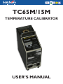
TC65M/15M
TEMPERATURE CALIBRATOR
USER’S MANUAL
Thank you
for purchasing a Scan-Sense temperature calibrator.
The products are manufactured by Scan-Sense AS in accordance with our high quality standards in design, choice of
components and workmanship in order to achieve maximum
customer satisfaction and to fulfil our vision to be our customers
“First Choice”.
The TC65M/15M is designed and manufactured by:
Scan-Sense AS
Bekkeveien 163
N-3173 Vear
NORWAY
Tel:
+ 47 33 36 30 00
Fax: + 47 33 36 30 01
Web: www.scansense.no
E-mail: [email protected]
Scan-Sense AS reserves the right to make improvments or alterations to our products without incurring any responsibility to make the same improvments or alterations to products previously sold.
SCAN-SENSE AS
All rights reserved. No part of this publication may be reproduced, stored in a retrieval
system, or transmitted in any form by any means, electronic, mechanical, photocopying,
recording, or otherwise without the prior permission of Scan-Sense AS.
All efforts have been made to ensure the accuracy of this handbook. We at Scan-Sense
are always striving to improve our products and handbooks, therefore we would
greatly appreciate being informed of any errors found in our product or in its manual.
The above notwithstanding, Scan-Sense can assume no responsibility for any errors in
this handbook or of their consequenses.
TC65M/15M User’s manual
Contents
1.
2.
3.
4.
5.
6.
7.
8.
9.
10.
Getting started FAST! .............................................
Page 3
Safety ...................................................................... Page 4
Why calibrate? ........................................................
Page 5
How often do I calibrate? ........................................
Page 6
How to use the TC65M/15M calibrator ...........................
Page 7
Maintenance ............................................................ Page 10
Specifications .......................................................... Page 10
Trouble shooting .....................................................
Page 11
Warranty .................................................................. Page 11
Appendix ................................................................. Page 12
DNV Certificate no. ________________________________
2
TC65M/15M User’s manual
Getting started FAST!
Don’t start a fire!! Read the safety chapter for your own and your environments
safety.
Read the chapter “Introduction to calibration” if you do not have the full and
whole understanding of the use of dry well calibrator as the TC65M/15M.
1. Make sure the supply voltage is in accordance with the description on
the label.
2. Make sure the calibrator well and the probe you want to calibrate is clean.
3. Place the probe in an appropriate hole in the well*.
4. Turn on the calibrator.
5. The display on the calibrator controller will show the actual well
temperature and the set point will show 25°C. Default is shown as °C.
See chapter 5. for switching the display to show °F.
6. Press the up and down buttons multiple times on the controller in order
to set the desired calibration temperature (set point). The display will
automatically switch to show the set point when the up/down buttons are
pressed. When pressing and holding one of these buttons the display will
start to count up or down. If the buttons are held continuously, the
counting speed will increase. The set point will not be active before you
move to the next step.
7. After setting the set point, the display will return back to show actual well
temperature 3 seconds after the last depressing of the set buttons.
You can now switch between set point and well temperature by pressing
the set button once. This will not affect the set point or anything else in
the process.
8. Let the temperature reach and stabilize at the set point. Check both the
calibrator and calibration object to determine if the temperature is stabile.
9. When both the calibrator and calibration object is stabile, note both
readings.
10. Set the next calibration point with the up/down buttons and repeat point
5 to 8.
11. When all desired calibration points are completed, set the set point to 25°C
and let the well temperature decrease to a temperature below 50°C
before you store the calibrator.
12. File the calibration data.
* If your probe has another diameter than those supplied, use an insert
adapter, drilled to the correct diameter. A more thorough description of the
above points is found in the chapter “How to use the TC65M/15M calibrator”.
3
TC65M/15M User’s manual
Safety
Incorrect use of dry well calibrators like the TC65M/15M can be hazardous.
Severe burns or fire may very easy be the result of incorrect use. Therefore
always see to that the assigned operators got the required skills to operate the
calibrator. Local fire and safety instructions may apply to the use of
instruments like the TC65M/15M.
The well in the calibrator can reach up to 650°C. This temperature will certainly cause burns and fire if something gets into the well. Ensure that the
workspace around and above the TC65M/15M is free from loose materials
that can catch fire. There should be nothing but the roof above the calibrator
(or at least 1m of clearance to a non flammable material).
The greatest risk is if the probe or insert adapter is removed from the well
when the calibrator still is hot. NEVER REMOVE HOT PROBES OR INSERTS
FROM THE WELL. Allow time to cool down the probe and insert before
removing and storing.
Never remove the cover of the calibrator unless you are a qualified service
technician. High voltages and temperatures will be exposed.
Always ensure that the air inlet in the bottom of the TC65M/15M is free
and not clogged by dust. Ensure that the fan is running. If not, do not use
the TC65M/15M as it will overheat and create a potential danger. Send the
TC65M/15M for repair. Ensure that the TC65M/15M and especially the well,
is clean and free for dust before use.
Some dry block calibrator users insist on using oil in the well to ensure better
thermal contact. If your unit has been filled with oil, thoroughly clean the well
for all traces of oil. Fumes from heated oil can be dangerous. Health damages,
fire and explosion may be the result. Oil remains can also create a carbon
buildup in the well (at high temperatures) that is nearly impossible to remove.
WARNING! If a wet object is inserted into a heated well, the TC65M/15M may
explode! The well can act as a launching tube for the probe and insert if undesired liquids or materials gets into the well.
Never leave a powered calibrator. Always work with the calibrator on a sturdy
workspace. In addition to the listed safety concerns, always add a good
portion of common sense to catch up unpredictable safety risks.
4
TC65M/15M User’s manual
Why calibrate?
The definition of the term “calibration” is:
To determine the difference between the object being calibrated with a known
reference and knowing the uncertainty in the process.
Adjusting the calibrated object in order to remove the error is of secondary
importance as long as the error is either within acceptable limits or the error is
used to calculate the real value.
Calibration is an important part of any quality insurance routines. When a
calibration routine is created, all aspects are taken into consideration by qualified personal so when an operator is making calibrations later, the process is
done the same way every time and ensuring that the results are comparable
and reliable.
By documenting the process and results, you are making the whole process
traceable. This way a lot of human errors can be eliminated, giving the
responsible operator piece of mind if something goes wrong.
Good quality is to achieve the accuracy you need and not far beyond. If your
demand is to keep the temperature in you process within e.g. 300 to 330°C,
define your accuracy needs to 315 +/-15°C. Your calibration process should
now ensure that your temperature instrument is within these limits and not
necessarily the peak performance of the specifications of the instrument. A
good rule of thumb is to double the accuracy demand for your calibration
compared to the process accuracy demand. This leaves the accuracy demand
for you calibration in the neighborhood of +/-8°C.
5
TC65M/15M User’s manual
The whole chain of elements involved in the calibration process creates errors
in the final reading. In this matters errors are expressed as uncertainty. Take
the following elements into account when considering the total uncertainty:
·
·
·
·
·
·
·
·
Temperature drift in the calibrator
Temperature drift in the calibrated instrument
Temperature gradients in the calibrator well
Differences in gradients caused by variance in probe mass (calibration
object)
Inaccuracy in the calibrator
Inaccuracy in the calibration object
Variance in thermal contact between the probe being calibrated and
the calibrator well
Reading error (if analog scale on the calibrating object)
Remember all these elements are NOT added to calculate final uncertainty. In
real life there is not likely that all uncertainty elements will be at the maximum
and in the same direction simultaneously! Therefore another way of calculation
is used. The formula is simple, but this is as far as we will go in this manual.
There is a lot of written material covering this issue on the market.
How often do I calibrate?
Depending on the importance of the accuracy in the process and the use
(or abuse) of the measuring equipment, the calibration intervals will vary. The
calibrating should take place in intervals no longer than what you can handle if
the process becomes out of specified limits.
If a calibration suddenly reveals a large deviation compared to the previous
calibration, you can trace back and identify the time span where errors may
have occurred and take actions thereafter. The shorter the calibration interval,
the shorter time span with possible errors. A normal interval for calibrating
a thermometer in a process should be about 1-3 months. If there is very
important to ensure the consistency of the accuracy, make simplified calibrations between scheduled calibrations with less calibration points (maybe only
one) and simplified documentation.
6
TC65M/15M User’s manual
How to use the TC65M/15M calibrator
We assume that you know the basic operation of the calibrator as described in the
“Get started fast” chapter. Here we are taking the points a bit further step for step.
1. Make sure the calibrator well and the probe you want to calibrate is clean.
This is important in order to remove unnecessary uncertainty in the process
created by carbon build up (above 500°C) and excessive pollution. Also
polluted well and probe can create poisonous gases. If calibrating an
electronic instrument, also make sure the contacts between the probe and
display unit is clean. Dirty contacts create resistance that affects the reading.
2. Place the probe in an appropriate hole in the well*.
Use a hole in well that is 0,2 to 0,6mm larger than the probe you are
calibrating. If no appropriate hole exists, use an insert adapter placed in the
largest hole. Insert adapters are available with several dimensions. There is
also important that the probe reaches the bottom of the well. If not the reading
will be very inaccurate.
3. Turn on the calibrator.
Self-explanatory.
4. The display on the calibrator controller will show the actual
temperature in the well
The default temperature when powering up will be the set point 25°C. The
display can be changed between °C and °F by pressing both set buttons when
power is switched on. The selection will be stored when turning on the unit
next time. The L1 indicator will show the chosen unit. The switch test indicator
will be indicated by L3. When a stable temperature is reached, the L2 indicator
point will stop flashing and light continuously.
There will always be a difference in the actual well temperature and the display reading. This is due to temperature gradients in the well. This difference
is largest during temperature increase and decent. The TC65M/15M internal
reference sensor is located, close to the bottom of the well so the correct
calibration depth is 1 to 2 cm from the bottom of the well. TC65M/15M is
calibrated with a 6mm PRT reference probe placed at the bottom of the insert
with 6,5mm hole.
7
TC65M/15M User’s manual
Also take into consideration the load the calibration object will employ to the
well. A large and heavy probe will extract more heat from the well and change
the gradient lines differently compared with a small and light probe.
5. Press the up and down buttons on the controller in order to set the
desired calibration temperature (setpoint). The display will
automatically switch to show the set point when the up/down buttons
are pressed.
When pressing and holding one of these buttons the display will start to count
up or down. If the buttons are held continuously, the counting speed will
increase. The setpoint will not be active before you move to the next step.
6. After setting the set point, the display will return back to show
actual well temperature 3 seconds after the last depressing of the
set buttons.
You can now switch between set point and well temperature by pressing
the set button once. This will not affect the set point or anything else in
the process.
7. Let the temperature reach and stabilize at the setpoint. Check
both the calibrator and calibration object to determine if the temperature is stabile.
During temperature rise and decent there will be a large difference in the well
temperature displayed and the actual well temperature. There will also be a
large difference in the actual well temperature and the temperature displayed
on the calibration object. Therefore the temperature has to equalize. Also allow
5 to 10 minutes for the process to stabilize after reaching the desired setpoint
before making readings.
8
TC65M/15M User’s manual
8. When both the calibrator and calibration object is stabile, note
both readings.
When the process is stabile as described in the previous point, note the reading of both the calibrator and the calibrating object. Make calculations for each
point that will give you the factor for calculating a more accurate value than the
reading of the calibrated object. Refer to the provided example for a calibration
certificate with report.
9. Set the next calibration point with the up/down buttons and repeat point 5 to 8.
To give the best repeatability we suggest always starting with the lowest
calibration point and work your way upward. Select calibration points that are
relevant i.e. If your target area in the process is 130 to 200°C, logical calibration points would be 100, 175 and 250°C. A simplified process would be only
150°C that may be used as a control calibration between scheduled calibrations.
10. When all desired calibration points are finished, set the setpoint to 25°C and let the well temperature fall to below 50°C before you store the calibrator
If you remove the calibrated probe from a very hot well, it will be prone to
damage (if Pt type) and it may be dangerously hot to touch.
The heating element will automatically be switched off in case set
temperature of 400°C or more has been in operation for more than 1 hour.
The display will in this case show “E40” and a new set point must be
selected before continuing.
11. Test of thermostats.
The TC65M/125M have a built-in test functions for thermostats. Connect the
alligator clips to the calibrators input function. Please pay attention to the fact
that thermostats react slowly to temperature changes.
9
TC65M/15M User’s manual
Maintenance
To ensure acceptable dependability we suggest annual calibration of the
TC65M/15M calibrator. Also make sure the calibrator is stored and handled
such a way that it is likely not to suffer from abuse. Keep the calibrator clean
and dry at all times. Polluted well will decrease accuracy. Clean the holes with
a small wire brush or sand paper on a piece of wire. Remove dust from the
well and internals with compressed air. This is important in order to avoid fire.
Also regularly compare the latest calibration with earlier in order to monitor if
there is a trend going in a certain direction. If a trend is accelerated or radically
altered, there may be wise to keep a closer eye at the calibrator and maybe
calibrate it more often or have it examined. This also applies to your calibration objects.
TC65M/15M is a dry well calibrator. Do not use oil in the well holes.
There are no user serviceable parts inside the calibrator. However, there is a
15A main fuse inside that may brake due to internal failure. A qualified service
person should be able to determine if the fuse can be replaced wit no other
actions or if the calibrator needs repair.
Technical information
TC65M
TC15M
Temperature range
30 to 650°C
-40* to 150°C
Resolution (display)
0,1°C
0,1°C
Accuracy
± 1,5°C
± 0,3°C
Stability
± 0,5°C
± 0,05°C
Heating time to max
40 min.
50 min.
Cooling time to min
65 min.
20 min.
Thermostat test
Yes
Yes
USB
Yes
Yes
Well depth
155 mm
110 mm
Well diameter
26 mm
19 mm
Power supply
230 VAC, 50 Hz
90-240 VAC, 60/50Hz
110VAC, 60 Hz
Power consumpsion
1600 Watt
180 Watt
Operating temp.
0 to 40°C
0 to 40°C
Dimension
117 x 300 x 245 mm
117 x 300 x 245 mm
Weight
Approx. 5.5 kgs
Approx. 5.5 kgs
10
TC65M/15M User’s manual
Trouble shooting
Unstability may occur if the mains supply voltage varies. This is sometimes the
case if the stability seems to be erratic for no reason.
Warranty
Scan-Sense standard warranty conditions.
11
TC65M/15M User’s manual
Appendix
The calibration certificate template may be used in most cases for your calibraion objects. Make copies of the page and fill in your own calibration results.
This is an explanation to the suggested points in the template:
(most are self explanatory and are not further described).
·
·
·
·
·
·
·
·
The “Certificate number” shall be a unique notification for the
certificate making it possible to separate certificates even if they cover the same calibration object. Note this number on a small sticker on the calibration object making it possible to trace the calibration.
In the first table note the data about the object you are calibrating.
“Calibration conditions” notes the temperature in the room during calibration. This may in extreme cases inflict the results.
The “Statement” in the template states that the calibrator has a
traceable calibration. In order to use this statement, make sure your calibrator really do have a valid traceable calibration. Better yet, also a written instruction describing how to maintain the calibrator.
In the column “Standard used” note the serial number for your TC65M/15M unit. Also note the number at the certificate for the latest calibration
of your TC65M/15M calibrator and the name of the company or organization
that performed the calibration. This way you will maintain the traceability
all the way from your calibration object to the interna tional standard on
top of the reference chain. Remember to update this number when your
TC65M/15M has been calibrated.
In the “Measuring report” table there is a column “TC65M/15M correction” that may be filled in if you have a calibration certificate for your TC65M/15M
stating measuring errors. By calculating the “TC65M/15M real value” you
will achieve better accuracy.
The “Measuring report” will at the last column state the error for the calibration object. This error should be considered if it is within acceptable
limits and can be ignored, or if the value must be used to calculate a more
accurate value.
At the bottom of the certificate the operator performing the calibration putting he’s or her sign. The person responsible for the correctness of the
process and calculations are also signing the certificate.
12
TC65M/15M User’s manual
Certificate of Calibration
Certificate number:……………..
Unit under test:
Serial number:
Calibration result:
Department: Passed:
Calibration Date:
Calibration due date:
Failed:
Calibration conditions:
Temperature:……………………
Statement:
The instrument described above has been calibrated using the below
described standard that is calibrated with traceability to international
standards. This calibration certificate is issued with a measuring report, and
shall only be fully reproduced.
Standard used:
Instrument: Model:
Serial No:
Temp.
TC65M/15M
calibrator
Cert No:
Traceability:
Measuring report:
TC65M/15M TC65M/15M TC65M/15M Test object
reading:
correction:
real value:
reading:
Test object
deviation:
Remarks:
· “Test object deviation” is calculated by subtracting “TC65M/15M real value” from “Test object reading”.
· The value “Test object deviation” tells how much the reading of the test object is off. A positive figure tells how much the reading is above the actual value. A negative figure tells how much below
Calibration performed by: …………………………………………..
13
Certified by:
…………………………………………..
Manual revision: Januar 2009
PS00080A
Copyrighted © 2009 Scan-Sense AS