1
SMC23A
SMC24A
SMC25A
SMC26A
/
/
/
/
SMC23B
SMC24B
SMC25B
SMC26B
Step Motor Controller
User's Manual
JVL Industri Elektronik A/S - September 1995
LB0038-01GB
Revised 14.5.96
CONTENTS
1.1 INTRODUCTION ........................................................................................................................... 2
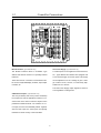
1.2 CONTROLLER CONNECTIONS ....................................................................................................... 3
2.0 BLOCK DIAGRAM OF THE CONTROLLERS .................................................................................... 6
2.1 POWER SUPPLY (TYPES SMC24 AND SMC26 ONLY).................................................................. 7
2.2 MOTOR DRIVER .......................................................................................................................... 8
2.3 USER INPUTS AND OUTPUTS...................................................................................................... 11
2.4 USER INPUTS ............................................................................................................................. 12
2.4 USER INPUTS ............................................................................................................................. 13
2.5 ANALOGUE INPUTS ................................................................................................................... 14
2.6 CW/CCW LIMIT INPUTS ........................................................................................................... 15
2.7 CONNECTIONS ........................................................................................................................... 16
3.1 INTERFACE CONNECTIONS ........................................................................................................ 17
3.2 INTERFACE ADDRESSING........................................................................................................... 19
3.3 COMMUNICATION RATE ............................................................................................................ 20
3.4 COMMAND SYNTAX .................................................................................................................. 21
3.5 CHECKSUM FACILITY ................................................................................................................ 22
3.6 MODULE INTERFACE (TYPES SMC23 AND SMC24 ONLY) ....................................................... 23
4.1 GENERAL ASPECTS OF CONTROLLER SOFTWARE ...................................................................... 24
4.2 COMMAND OVERVIEW .............................................................................................................. 27
4.3 SYSTEM COMMANDS................................................................................................................. 30
4.4 MOTOR COMMANDS ................................................................................................................. 33
4.5 USER INTERFACE COMMANDS .................................................................................................. 43
4.6 FLOW CONTROL COMMANDS .................................................................................................... 46
4.7 EXTENDED COMMAND SET (TYPES SMC23/24 ONLY) ............................................................. 51
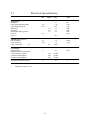
5.1 ELECTRICAL SPECIFICATIONS .................................................................................................... 63
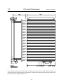
5.2 PHYSICAL DIMENSIONS (TYPES SMC23 AND SMC25) ............................................................. 65
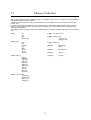
5.3 MEMORY UTILIZATION.............................................................................................................. 67
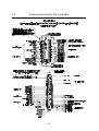
5.4 CONNECTORBOARD FOR THE CONTROLLER ............................................................................... 68
5.5 MOTOR CONNECTIONS .............................................................................................................. 69
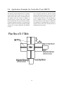
5.6 APPLICATION EXAMPLE FOR CONTROLLER TYPE SMC25......................................................... 70
5.7 INDEX ....................................................................................................................................... 76
1
1.1
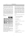
Introduction
Stepper Motor Controllers Types SMC23-26 provide a range of easy-to-use, cost-effective controllers
for stepper motors. They combine an advanced
motion-control indexer and motor drive in a single
unit.
The Controllers can be used as stand-alone units
or connected to a terminal or personal computer
(PC) via the RS232C/V24 interface. They are equipped with inputs and outputs which provide the
user with a high degree of flexibility for tailoring
configuration to the specific application. The Controllers are ideal for controlling small milling machines and drills, handling- and feeder units, etc., where quick and precise motion control is required without the use of components which are large or
costly.
The SMC23-26 Controller series provides the following features:
Types SMC23 and SMC25 cannot be powered directly from a mains supply, but are primarily intended for use in larger systems where a central power
supply is used for powering 2 or more controllers.
Controller Types SMC23 and SMC24 are advanced
models which include an extended set of program
commands and User Registers for storing parameters and intermediate results. In addition, these
models include a Module Interface which enables
connection of extension modules such as a keyboard/display module and additional user inputs
and outputs. The Module Interface enables connection of up to 31 external modules including other
controllers.
The SMC Series provides the following basic features:
• 15-45V DC supply (Types SMC23/SMC25)
115/230V AC supply (Types SMC24/SMC26).
• RS232C/V24 communication.
• Simple programming.
• Max. stepping frequency 15kHz.
• Connection of up to 7 controllers on the same RS232
interface bus.
• Baud Rates: 110 - 9600.
• Small physical dimensions:
All Controller Types are available in two versions
with 3A and 6A motor drives respectively. All Controllers are equipped with 3 digital User Inputs and
3 digital User Outputs for general use. 6 analogue
inputs can be used for example when a pressure
transducer is used to transmit measurement or
control values to the Controller.
All inputs and outputs for fully overload protected.
The motor driver is further equipped with shortcircuit protection which disconnects current to the
motor in the event of a short-circuit.
Types SMC24 and SMC26 are equipped with an
integral power supply which enables direct operation from a mains supply.
SMC23/25: bxhxd: 46.5 x 100 x 160 mm
SMC24/26: bxhxd: 106.5 x 111 x 171 mm
• Thermal protection.
• 3 User Inputs.
• 6 Analogue Inputs.
• 1 Stop Input.
• 3 User Outputs (each 500mA).
• Connection via DIN41612 socket or connector board
CON10/CON10P.
• Mounting in 19" rack or flush mounting.
2
1.2
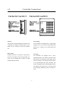
Controller Connections
Interface :
Power Supply :
The RS 232C Interface enables the Controller to be
The Controllers are operated from a single supply
connected to a computer or terminal. Up to 7 Con-
voltage: from 15 to 45 V DC for Types SMC23 and
trollers can be connected on the same interface
SMC25, and 115/230V AC for Types SMC24 and
bus.
SMC26.
Motor Output :
User Inputs :
Enables connection of a 2-phase or 4-phase step-
The Controllers are equipped with 4 noise-
per motor. The output is short-circuit protected. The
suppressed inputs, one of which is reserved for the
motor can be controlled with a speed of 15000
Stop function. The remaining 3 User Inputs can be
Full/Half-steps per second.
used, for example, for connecting inductive sensors
or for synchronization with other controllers. The
inputs are equipped with a Schmidt-trigger function
and operate in the range 5-30 V. The User Inputs
are all optically isolated from other Controller circuitry.
3
1.2
Controller Connections
User Outputs :
Analogue Inputs :
The Controllers are equipped with 3 User Outputs
The voltages at the Controller's 6 Analogue Inputs
which for example can be used to drive small DC
can be read using a set of program commands,
motors, or to synchronise the unit with other con-
thus enabling control of a motor's maximum speed,
trollers.
absolute or relative distance, etc., by the applicati-
Each output can supply up to 500mA and operates
on of a voltage to one of the 6 Analogue Inputs.
in the range 5-30 V.
The inputs accept voltages in the range 0 - 5.10V,
In addition, the User Outputs are short-circuit pro-
and are protected against short-duration overloads
tected and optically isolated from other Controller
up to 45V.
circuitry.
4
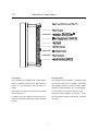
1.2
Controller Connections
Module Interface (Types SMC23/24 only)
User Power Supply (Types SMC24/26 only)
The Module Interface fitted to Controllers Type
To enable power to be supplied to external sensors,
SMC23 and SMC24 consists of 2 optically isolated
etc., Types SMC24 and SMC26 are equipped with
terminals.
a User Power Supply on the rear panel. This supply
These are used for connection to all external modu-
can be adjusted to one of 3 settings to give a volta-
les such as keyboard/display modules, input/output
ge of either: 5V DC; 24V DC; or continuously adju-
modules, etc.
stable from 5 to 30V DC.
The User Power Supply output supplies a current of
0.5A regardless of voltage level.
CW/CCW Limit Inputs (Types SMC23/24 only)
The CW (clockwise) and CCW (counter-clockwise)
Limit Inputs are used in applications where it is crucial that the motor does not advance beyond some
predefined mechanical limits. On activation of a Limit Input, the motor is immediately halted. Together
with the User Inputs, the Limit Inputs are optically
isolated from other circuitry in the Controllers.
5
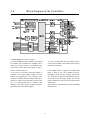
2.0
Block Diagram of the Controllers
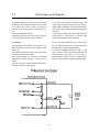
2.1 Power Supply (Types SMC23 and SMC25).
To ensure powering of the Controllers is as simple
It is also recommended that the cables used to
as possible, the Controllers are supplied from a
connect the Controller to the external power supply
single 15 to 45V DC supply. The Controllers' inter-
are minimum 0.75mm².
nal circuitry ensures the correct supply for the interface, control circuitry, etc.
If the voltage used to supply the Controller falls
In the event of incorrectly connected polarity or
below a level of 10V, the Controller will auto-
overload of the power supply voltage, the Con-
matically be reset and any program instructions,
trollers are fuse-protected. If an overload occurs,
etc., will be lost. Provision should therefore be ma-
the power should be disconnected and the fuse re-
de to ensure that the supply voltage does not fall
placed. To ensure correct operation of the Control-
below a minimum of 15V, even in the case of mains
ler, it is recommended that a capacitor (min.
voltage drop.
5000µF) is connected across the positive and ne-
The program in the permanent memory (E PROM)
gative terminals of the external supply.
will not be lost.
2
6
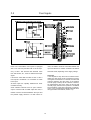
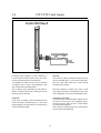
2.1
Power Supply
(Types SMC24 and SMC26 only)
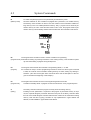
The User Supply Output and the Controller's internal supply (40V DC) are available at terminals on
the rear panel of the Controllers.
The Controller's internal supply can thus be used for
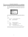
powering other controller's in the motion control system. The red LED named P. Limit (see drawing)
will light up if the power consumption from the
power supply of the controller exceeds the 120W
maximum it can supply.
Controllers Types SMC24 and SMC26 are equipped
with an integral supply for powering from an AC
mains supply.
This supply also provides a User Supply Output
which can be used for powering external equipment.
The User Supply can be adjusted to 1 of 3 settings
(see above) as follows:
Position 1 provides a fixed supply voltage of 5V DC.
Position 2 provides a fixed supply voltage of 24V
DC. Position 3 provides a continuously adjustable
supply voltage in the range 5 to 30V DC.
Regardless of the voltage setting, the User Supply
Output provides a continuous current of 0.5A. If this
current is exceeded, the supply will automatically
reduce the supply voltage to ensure overload does
not occur.
The external supply is thus protected against shortcircuiting. Depending on the selected supply voltage, the “Voltage” LED (see drawing) will vary in light
intensity.
In the event of voltage overload in the mains supply,
the Controller's secondary or primary fuse will be
blown. If this occurs, the Controller should be
disconnected from the mains supply and the fuse(s)
replaced.
Primary and secondary fuses are located in the fuse
holder in the mains socket.
7
2.2
Motor Driver
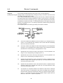
The Controller is intended for use with 2- or
components in the connection between the driver
4-phase stepper motors. Controller Types SMCxxA
and the motor.
provide a motor phase current of up to 3A, while
In some cases, this high-frequency noise can result
Types SMCxxB provide a phase current of up to
in unwanted interference of other electronic equip-
6A. The phase current is continuously adjustable.
ment close to the stepper-motor system. To avoid
The
acceler-
this problem, screened cable should be used to
ation/deceleration current and constant speed cur-
connect the Controller to the stepper motor, as illu-
rent can be set individually. The current is control-
strated above.
motor
standby
current,
led via a set of software commands as described in
Section 4.4.
The Controller Driver consists of a 2-phase bipolar
chopper driver. This type of driver results in optimum utilization of the motor since current is continuously supplied to both phases of the motor.
The chopper-driver regulates the current at a frequency of 22kHz (nominal) thus ensuring that the
motor control does not produce audible noise.
The switching time of the Driver is very small
(<200nS), which can result in high-frequency noise
8
2.2
Motor Considerations
It should be noted that the lower the self-inductance of a motor the better, since self-inductance greatly influences the motor driving torque at high speeds. The torque is also affected by the current supplied to the motor.
This is also illustrated by the following equation:
Applied Voltage
Phase Current =
Phase Inductance * Driving Frequency
It should be noted that the phase inductance of a motor is dependent on the other phases during operation. Individual motor manufacturer's specifications of phase induction are normally measured statically.
The applied voltage is regulated by the driver so that the phase current is adjusted to the required level. In practice this means that if a motor with a large phase inductance, e.g. 100mH, is used, the driver cannot supply the
required phase current at high speeds (high rotational frequencies), since the output voltage is limited.
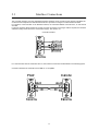
If a 4-phase motor is used, it should be connected as shown below. The motor phases should be connected in
parallel to result in as low a value of self-inductance as possible. The phases can also be connected in serial,
but this will limit the top speed of the motor. If the phases are connected in serial, the motor will typically provide
greater torque (at low speeds).
9
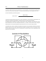
2.2
Motor Driver
Selection of Step Resolution
The driver can be configured to operate with either full-, half-, 1/4 or 1/8 motor steps. It is often an advantage to
operate with fractional steps since this increases the resolution per motor rotation. Operating the motor with half, 1/4 or 1/8 step resolution often eliminates the need for mechanical gearing.
Another advantage is that resonance problems, which are almost unavoidable with full-step operation, can normally be avoided.
A stepper motor always has a resonance frequency which can vary depending on the motor load and results in
loss of torque.
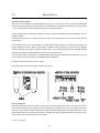
The Controller can be set to normal (NOR) or extended (EXT) step resolution. For normal step resolution, the
jumper is placed in position “NOR” which makes it possible to switch between Full- and Half- step operation
using the dipswitch. If the jumper is placed in position “EXT”, 1/4 or 1/8 step operation can be selected using the
dipswitch. The jumper is placed between the “Power” and “Overload” LEDs.
You have free access to this jumper on Controllers SMC23 and SMC25, whereas the front panel has to be removed to gain access to the jumper on Controllers SMC24 and SMC26.
On delivery the step resolution is set to 1/2 step.
The drawing below shows how the step resolution can be set:
Overload Protection
The Motor Driver is short-circuit protected. If the motor current exceeds 3.2A (6.4A) for more than 2ms, the voltage is disconnected from the outputs to prevent overload or damage to the motor. An instantaneous shortcircuit of any two arbitrary output terminals has no effect and will not damage the Controller, although an Overload indication will occur. To reset the Controller, the power must simply be disconnected for a minimum of 5 seconds, after which normal operation can be resumed.
() Valid for Types SMCxxB
10
2.3
User Inputs and Outputs
To ensure flexibility and ease of use, the Controller
If one of the User Outputs is short-circuited or the
is equipped with 3 digital User Inputs and 3 digital
output current exceeds 700mA, the "Overload" in-
User Outputs which can be used for a variety of
dicator blinks. In addition the voltage is disconnec-
purposes. A fourth input can be used as a Stop in-
ted from the User Output at which the overload has
put.
occurred.
All inputs are optically isolated.
To reset the Controller, the output-supply should be
Equipment connected to the User Inputs and Out-
disconnected for a minimum of 5 seconds, after
puts must be powered from external supplies.
which normal operation can be resumed.
User Outputs.
Each of the output terminals is the + switch termi-
The Controller's User Outputs can be used for con-
nal, i.e. that the load must be connected between
trol of secondary functions such as actuators, small
the output and ground (see figure below).
motors, etc.
To enable compatibility with logic circuitry, a "pull
This enables the stepper motor to be synchronized
down" resistor should be connected between the
with the surrounding environment.
output terminal and ground. For TTL logic, a
The 3 User Outputs are controlled via software
1kOhm resistor should be used; for CMOS logic a
commands and each provide a current of up to
resistor of approximately 10kOhm should be used.
500mA.
They are protected against inductive-load transients and are short-circuit protected.
11
2.4
User Inputs
Each of the Controller's User Inputs is equipped
used, the resistor must be connected between the
with a 1st. order low-pass filter with a cut-off frequ-
Input and Ground. A resistor of 500Ohm to 5kOhm
ency of 1kHz. This ensures that electrical noise
should be used, depending on the supply voltage.
from start motors, etc., does not influence the input
signal.
Stop Input
It should be noted that the state of each of the 3
If it is required to stop the motor movement immediately, the Stop Input can be connected to ground.
If the ground connection is re-moved, the motor will
continue operation and the value of the Position
Counter (step counter) will be retained. However,
an instantaneous stop of the motor in this way will
normally imply that the motor position is undefined
since activation of the Stop Input does not take account of the pre-defined acceleration/decele-ration
ramp (see Motor Commands, Section 4.4).
User Inputs is undefined if no connection is made
to the input.
All User Inputs are optically isolated from other
Controller circuitry.
Some inductive sensors have an open collectoroutput. If sensors with an NPN output are used, a
resistor must be connected between the Input and
the positive supply terminal. If a PNP sensor is
12
2.4
User Inputs
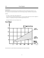
Input Hysteresis.
All User Inputs are noise-protected and are compatible with commonly used logic types: CMOS, TTL, etc.
The hysteresis of the Inputs is dependent on the connected supply voltage, as illustrated in the figure below.
Example:
User Input 1 is used, and the supply voltage is 24V.
As can be seen from the figure, the Input is logic "1" if an input voltage greater than 13.3V DC is applied. To
set logic "0", the applied input voltage must fall below approximately 5.3V DC.
The trigger tolerances on the input voltage is ±10%.
See also Section 4.5 (User Interface) for further details of User Inputs and Outputs.
13
2.5
Analogue Inputs
The Controller is equipped with 6 Analogue Inputs
which can be scanned and read using software
commands as described in Chapter 4.
The Analogue Inputs can be used for example to
control the speed of the stepper motor using an
analogue input voltage.
The inputs are protected against short-duration
overloads up to 45V.
Each time the controller measures the signal at an
Analogue Input, a total of 16 samples are made.
These are then averaged to minimise the possibility
that an instantaneous noise impulse, for example
from the motor driver, influences the measurement.
The Analogue Inputs can also be used as conventional User Inputs (digital inputs), although without
input hysteresis or optical isolation.
No special requirements are necessary to use the
Analogue Inputs in this way. At any time, an Analogue Input can be used as either a true analogue
input or as a standard User Input (digital input).
For further details, see Chapter 4 - commands ±A,
DA, G±A, JCA, NA, r, s, t, U, VA, W.
The Analogue Inputs accept voltages in the range
0V to 5.10V. The Controller uses an 8-bit A/D converter which results in a resolution of 256 steps. Each step therefore corresponds to 20.0mV at the
Input.
To avoid incorrect measurements, the Analogue
Ground AGND (see Section 2.7) must be used with
the 6 Analogue Inputs.
See also the Electrical Specifications (Section 5.1)
for further information.
Each of the Analogue Inputs is equipped with a 1st.
order low-pass filter which suppresses frequencies
above 10kHz.
14
2.6
CW/CCW Limit Inputs
In stepper motor systems it is often necessary to
CW Limit.
set up certain mechanical limits which the motor
If the motor is rotating clockwise and the CW Limit
must not exceed under any circumstances.
Input is activated (logic "1"), the motor will be stop-
To enable these Limits to be set up, the Controller
ped. The CCW Limit Input has no effect during
is equipped with 2 inputs: CW (Clockwise Limit)
clockwise motor rotation.
and CCW (Counter-clockwise Limit).
One of these 2 inputs, depending on the actual di-
Note that activation of either of the CW or CCW
rection of rotation of the motor, will stop the motor
Limit Inputs will result in instantaneous stop of the
when the input is activated.
motor, regardless of any pre-set deceleration ramp.
CCW Limit.
Inactivation of the motor
If the motor is rotating counter-clockwise and the
A special feature of the Controllers enables the driver current to the motor to be completely disconnected so that the motor is free to rotate without
any mechanical resistance.
This is done by activating both end-of-travel inputs,
CW and CCW, simultaneously.
CCW Limit Input is activated (logic "1"), the motor
will be stopped. The CW Input has no effect during
counter-clockwise rotation.
15
2.7
Connections
Connections for SMC23, SMC24, SMC25 and SMC26
16
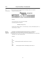
3.1
Interface Connections
The Controller Interface uses the widespread RS232C standard, which provides a great degree of flexibility since all Personal Computers and standard terminals have provision for using this communication standard.
For operation of the Controller via an RS232C interface, the 3 standard RS232 connections Rx, Tx and Ground
are used.
In general, interface cables should not exceed 10 metres in length but if a longer cable is required, the interface
checksum facility should be used to ensure data integrity. See Section 3.5.
Controller Interface:
For communication with the Controller via a PC, the interface connections are illustrated in the following figures.
Connection between the Controller and an IBM AT or compatible :
17
3.1
Interface Connections
Connection between the Controller and an IBM XT/PS2 or compatible :
18
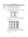
3.2
Interface Addressing
The Controller can be configured to respond to all communication on the interface ("point-to-point" communication). In addition, it is possible to connect up to 7 Controllers on the same interface bus, i.e. "multipoint" communication. For multipoint communication the Controller DIP switches must be set to assign a unique address to each controller on the interface bus. In this way, each controller only responds to interface commands which are
preceded by its preset address. To configure Controllers for multipoint addressing, the DIP switch marked Tx-PD
on one (and only one) of the Controllers must be set to ON. For the remaining Controllers in the multipoint configuration, Tx-PD must be set to OFF. For point-to-point communication, Tx-PD is set to ON on the Controller.
In order to ensure data integrity during communication, it is recommended that the interface checksum facility is
used. Checksum is enabled by setting the CHS DIP-switch to ON. For further details, see Section 3.5.
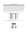
The DIP switch settings for configuring the interface address on Controllers are given in the following table:
IMPORTANT! :
A0
A1
A2
0
1
0
1
0
1
0
1
0
0
1
1
0
0
1
1
0
0
0
0
1
1
1
1
Address
1
2
3
4
5
6
7
Protocol
Point to point
Multipoint
Multipoint
Multipoint
Multipoint
Multipoint
Multipoint
Multipoint
If the address switch settings are changed, the Controller must be reset by switching off and
on the power for the new address to take effect.
19
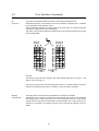
3.3
Communication Rate
Baud Rates of 110 to 9600 Baud can be selected for communication using the Controller's RS232C interface.
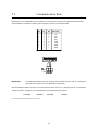
The Baud Rate is configured by setting 3 DIP switches, as shown in the following table.
IMPORTANT! :
B0
B1
B2
Baud Rate
0
1
0
1
0
1
0
1
0
0
1
1
0
0
1
1
0
0
1
1
0
0
1
1
110
150
300
600
1200
2400
4800
9600
If the Baud Rate setting has been changed, the Controller must be reset by switching the
power off and on again for the new Baud Rate to take effect.
Note that the Baud Rate must also be set to the selected value on the PC or terminal used for communication
with the Controller. In addition, the communication protocol should be set as follows:
(1 start bit)
7 data bits
odd parity
() A start bit is always used with RS232C/V 24 protocol.
20
1 stop bit
3.4
Command Syntax
Interface communication with the Controller must ful fill the following command syntax:
Address
Address :
Command
Argument
Checksum
Return
It is only necessary to specify the Controller Address if more than 1 Controller is connected to the
interface (multipoint configuration). The specified Address is a value in the range 1 - 7.
Command :
The command character(s) to be transmitted to the Controller. See the Software Description in
Chapter 4 for details of the Controller commands.
Argument :
The command arguments if any. Certain commands such as the K (Kill) or Z (Smooth Stop)
commands have no argument. (See Software Description).
Checksum : The checksum can be used if long communication lines are used between the Controller and PC
or terminal. The checksum ensures integrity of data transmission on the interface. If an error
occurs, an error message (E1) will be received. It is then necessary to re-transmit the command string (see following page).
Return :
ASCII character 13. The return character tells the Controller that the command string is complete and interpretation of the command can be initiated.
21
3.5
Checksum Facility
Electrical noise from sources such as electrical motors is a common occurrence in industrial applications. This
noise can be completely random in nature and despite effective electrical filtration electrical noise cannot be eliminated completely. In applications where it is vital to ensure that the system operates precisely as required, it is
therefore essential to select a communication rate (Baud Rate) that is not too high. Moreover, the interface cable
used to connect the Controller to a PC or terminal should not exceed 10m in length. A typical command string
used for interface communication with the Controller will be of the following form:
1A3%
In the above example, multipoint communication is used and the command is being transmitted to a Controller
which has address 1. The command is being sent to activate output number 3 (A3). The communication checksum for transmission of a command is determined as follows. First, the ASCII value of each character in the
command string is determined. The ASCII values are then summed and the result divided by 128. The integerresult of the division is discarded, while the remainder is used as the checksum. Calculation of the checksum for
the above example is thus as follows:
Address character
1
= ASCII 49
Command character A = ASCII 65
Argument character 3 = ASCII 51
Sum + remainder = (49+65+51)/128
Checksum = Remainder * 128
If an error occurs during transmission of the command string, the checksum will be incorrect and the Controller
will return the error message "E1" indicating that the Controller could not interpret the received command string.
The command must then be re-transmitted. If the Controller continues to transmit "E1", the interface Baud Rate
should be reduced or a shorter cable used to connect the computer to the Controller.
The Checksum facility is activated by setting the CHS DIP-switch to ON.
IMPORTANT! :
If the checksum switch setting is changed, the Controller must be reset by switching the
power off and then on for the new setting to take effect.
22
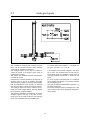
3.6
Module Interface
(Types SMC23 and SMC24 only)
Controllers Type SMC23 and SMC24 can be con-
If the communication distance between 2 units in a
nected to external modules such as an31, in-
system exceeds 25 metres, the DIP switch marked
put/output-module, keyboard/display-module etc.
TERM must be set to the ON on those units which
Connection to external modules is made via the
are located more than 25 metres apart.
Controller's RS485 serial interface using the two
See the User Manual for the module in question for
terminals marked "A" and "B".
details of DIP switch settings.
All external module functions are controlled via this
interface. Up to 31 modules (and at least 1 motor -
Module Addresses:
controller) can be connected to the interface bus.
In communication systems where several modules
The RS485 Interface offers several advantages in
are connected together, each unit must be assig-
that the interface operates with a balanced output
ned a unique address in the range 1 to 31.
and has low impedance. In addition, the Control-
The above illustration shows how addresses in a
ler's RS485 interface is optically isolated from other
typical system are set.
Controller circuitry.
Note that care must be taken to ensure no two modules use the same address. If the module addres-
The RS485 Interface is protected against transients
ses are not unique, the Controller will terminate
on the cable connecting the Controller to external
program execution and an error message will oc-
modules. These factors enable communication at
cur.
long distances despite the presence of electrical
Note that the Controller's address is the same as
noise.
that used for RS232 communication. (See Section
It is recommended that twisted-pair cable is used
3.2.)
for connection between the Controller and other
The address of each module should be set in ac-
modules on the interface.
cordance with the instructions given in the respective module's User Manual.
23
4.1
General Aspects of Controller Software
Before the individual software commands are de-
Position Counter.
scribed in detail, it is necessary to describe some
The Position Counter is a storage register which
general aspects of the Controller software structu-
keeps track of the motor's current position during
re.
operation. The Position Counter can be reset by the
I - (Initialise) or H (Home)command (see Sections
The Controller is equipped with 2 types of storage
4.3 and 4.4). The Position Counter's contents can
memory, both of which are accessible to the user.
also be read or changed using the commands V1
These are used for storing programs and operatio-
and f[±n].
nal parameters sent from a computer or terminal.
When the Position Counter reaches its maximum
value of +8,388,607 or -8,388,608, the motor stops
automatically.
The first of these storage memories is referred as
the "working memory" in the following pages. The
Controller's working memory is used during con-
Command Descriptions.
nection to a computer or terminal. The working
The following pages (Sections 4.3 to 4.6) describe
memory is a volatile memory; its contents are de-
each of the commands used for programming the
leted when the Controller is switched off. The wor-
Controller.
king memory can also be used for storing instructi-
To avoid any misunderstanding regarding the use
ons during programming.
of the commands and command syntax, the following text convention should be noted:
The second of the Controller's storage memories is
an E²PROM, i.e. a non-volatile memory which re-
Each command is described by one or more com-
tains its contents when the Controller is switched
mand characters followed by a word in pa-
off.
Controller's
rentheses. The actual command used to program
"permanent memory" in the following description.
This
is
referred
to
as
the
the Controller using the command syntax consists
The Controller's permanent memory is intended for
of the characters, not the word which is included in
use when the Controller is used as a Stand alone
the description as a mnemonic. Note that many of
unit, i.e. is not connected to a computer or terminal.
the command descriptions include examples of the
Use of the permanent memory enables the Con-
command string.
troller to begin execution of pre-programmed in-
Almost all commands are followed by one or more
structions without requiring connection to an exter-
parameters: either a value, or a plus (+) or minus (-
nal PC or terminal.
) sign. It is important that the speci-fied numeric
Permanent memory can also be used if the Con-
value is within the permitted range since the Con-
troller is connected to a PC or terminal. In this case
troller will not interpret parameters outwith the allo-
it is typically used to store frequently used program
wable range.
sequences which can be pre-programmed and
downloaded to the permanent memory.
See also Section 3.4 for details of the Controller
command syntax.
24
4.1
General Aspects of Controller Software
Operating Modes.
A typical sequence for programming the Controller
The Controller can be operated in 1 of 3 modes:
is as follows:
1) Standby Mode.
Mode:
Standby Mode occurs after a K (Kill), Z
(Smooth Stop) or PX (Program Exit) com-
1)
Controller switched on.
Standby
PO (Program) command
Program
mand, and after execution of a program.
2)
2) Programming Mode.
keyed-in.
This mode is used when a program is read
in to the Controller or to edit an existing pro-
3)
gram. Use the PO (Program) or PE (Program
Required sequence of
Program
program commands keyed-in.
Enter) command to set the Controller to Programming Mode.
4)
PX (Program Exit) command
Standby
keyed-in, after which the
3) Execute Mode.
Controller is set to Standby Mode.
The E (Execute) command is used to execute the program currently in the Controller's
5)
working memory.
E (Execute) command
Execute
keyed-in
Program execution stops when all commands have been executed or if interrupted
*
The entire program is then
by a K or Z command. Thereafter, the Con-
executed, unless an interrupt
troller returns to Standby Mode.
occurs via K (Kill) or Z (Smooth
Stop) command.
Programming.
6)
The program can be stored in
When creating a new program, the first command
permanent memory by keying-in
is always PO, i.e. the Controller is set to Program-
the M - (Memory Save)
ming Mode. The actual program commands can
command.
Standby
then be keyed-in.
Once all the required commands have been programmed, the E command is used to switch the
It should be noted that at power-up, the error mes-
Controller to Execute Mode and the program is
sage E1 will probably be received when communi-
executed. To store the program in permanent mem-
cation is first established between the Controller
ory, the M (Memory save) command can be used
and a PC/terminal. This is due to transients which
once program execution is complete. Programming
arise on the interface cable when the computer or
Mode can also be interrupted using the PX
Controller is switched on.
(Program Exit) command, in which case the Controller will be set to Standby Mode.
25
4.1
Controller Response
Each time the Controller receives a command or query via the interface, it responds to the PC or terminal with a
short response string. The syntax of the response string is as follows:
Reply Code
Argument
Checksum
Carriage-Return
Reply Code - The Reply Code is the actual response to the received command and is one of the following:
Y =
(Yes) The command has been received and will be, or has been, complied with.
B =
(Busy) The Controller is busy with program execution and is not ready to receive
the command or query.
R =
(Ready) The Controller is ready to execute a command or respond to a query.
V =
(Verify) Position or User Input/Output status. This message will only occur if the Controller is queried
about the status. See the descriptions of the V1 and V2 commands in Sections 4.3 and 4.5 for further
details.
E =
(Error) An error has been found in the received command and the Controller is not able to comply with
the command. This response returns an argument which indicates the type of error as follows:
E1 -
Parity Error after receiving one or more characters. Checksum Error. The received command
string was too long.
E2 -
The command argument is too long or is unnecessary.
E3 -
The working memory is full.
E4 -
Unknown command or the Controller is unable to comply with the received command.
E5 -
The Position Counter has exceeded its maximum of -8,388,607 or +8,388,607 steps, the motor
has been stopped. Error in Parameters ( R, S, T ).
E6 -
An error occurred during transmission to or from the Controller's Permanent Memory.
Argument -
An argument to the response will only occur with E (Error) or V (Verify) messages. The argument consists of 1 to 7 characters.
Checksum - A checksum value is only included in the response string if the checksum facility is
enabled via the DIP switch setting on the Controller (set to ON).
See the description of the checksum facility in Section 3.5 for further details.
Carriage-Return - Terminates the response string. ASCII-value 13.
26
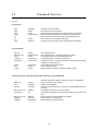
4.2
Command Overview
System Commands :
E
f [±nnnnnnn]
F
I [n]
K
M
PE
(Execute)
(Forcing Pos.)
(Feedback)
(Initialize)
(Kill)
(Memory)
(Program Enter)
PO
(Program)
PX
Q
TP
V1
X
Z
(Program Exit)
(Query)
(Temperature)
(Verify)
(Recall)
(Smooth Stop)
Starts program execution.
Reads in new position.
Status query to the Controller.
Resets Controller Registers (software reset).
Stops execution of current program.
Saves working program in Permanent Memory.
Sets the Controller to Programming Mode without erasing existing
program in working memory.
Sets the Controller to Programming Mode. This command erases
any program instructions already in working memory.
Exits Programming Mode. Returns to Standby Mode.
Displays the program currently stored in Working Memory.
Returns the current temperature of the Controller.
Returns the Position Counter value.
Loads program from Permanent Memory into Working Memory.
Stops program execution slowly taking account of deceleration
ramp.
Motor Commands :
[±nnnnnnn]
±A [n].[n1-n2]
CR [nnnn]
CS [nnnn]
CT [nnnn]
g [±]
G [±nnnnnnn]
G±A [n].[n1-n2]
H [±]
N [n1n2.n3n4]
NA [p1.p2]
R [nnnnn]
RT [nnnn]
RS [nnnnn]
S [nnnn]
T [nnnnn]
r [n1.n2]
s [n1.n2]
t [n1.n2]
VR
VS
VT
(Current Ramp)
(Current Start)
(Current Top)
(Velocity)
(Goto)
(Goto)
(Home)
(Input Setup)
(Input Setup)
(Ramp)
(Ramp Time)
(Ramp Slope)
(Start Rate)
(Top Rate)
(A/D Ramp)
(A/D Start Rate)
(A/D Top Rate)
(Verify Ramp)
(Verify S. Rate)
(Verify T. Rate)
Relative positioning given by direction of rotation (+/-) and number
of steps.
Relative positioning controlled by voltage at Analogue Input.
Determines motor current during acceleration.
Determines motor current when stationary.
Determines motor current at top speed.
Continuous operation forward/reverse.
Absolute positioning.
Absolute positioning controlled by voltage at Analogue Input.
Resets motor and electronic circuitry.
Starts/stops motor in accordance with User Inputs.
Starts/stops motor in accordance with Analogue Inputs.
Acceleration/deceleration parameter (1-10000 steps).
Acceleration/deceleration parameter (0.01-10 seconds).
Acceleration/deceleration parameter (10-30000 step/s²).
Minimum speed.
Maximum speed.
Same as R, controlled by voltage at Analogue Input.
Same as S, controlled by voltage at Analogue Input.
Same as T, controlled by voltage at Analogue Input.
Returns the current acceleration/deceleration parameter.
Returns the current Start Rate parameter.
Returns the current Top Rate parameter.
27
4.2
Command Overview
(continued)
User Interface :
A [n]
C [n]
U [n]
VA [n]
VA
V2
W [n]
(Activate)
(Clear)
(Until)
(Verify Ainput)
(Verify)
(Wait for)
Activates one of the outputs.
De-activates one of the outputs.
Repeats program(segment) until a specified input is activated.
Returns (measures) voltage at one of the 6 Analogue Inputs.
Returns (measures) the logic levels of the Analogue Inputs.
Returns status of user inputs and outputs.
Pauses program execution until a specified input is activated.
D [nnn]
DA [n].[n1-n2]
J [n1]
JC [n].[n1]
JCA [p].[n1]
(Delay)
(Analog Delay)
(Jump)
(Jump Cond.)
(Jump Cond.)
JS [n1]
RET
L [nnn]
(Jump Sub)
(Return)
(Loop)
Wait a specified time.
Wait a specified time controlled by analogue voltage.
Unconditional jump to a specified program line.
Conditional jump to a specified program line.
Conditional jump to a specified program line when specified voltage
is applied to Analogue Input.
Unconditional jump to sub-routine.
Return from sub-routine.
Repeat program segment a specified number of times.
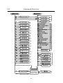
Flow Commands :
Command Overview - Extended Command Set (Valid only for Types SMC23/24)
+-/*
VR[0-510]
I[5-7]
con=[n]
(Verify)
(Initialize)
(Convert)
PRINT[n1.n2.n3]
IF [p1 m p2]
(PRINT)
(IF)
INPUT[n1.n2.n3]
AO[a].[o]
CO[a].[o]
(INPUT)
(Activate)
(Deactivate)
Arithmetic operators: addition, subtraction, division, multiplication.
Return contents of User Register.
Initialize User Registers.
Specify conversion between current and a user-specified measurement unit.
Print Register contents to external module.
If expression specified by command arguments is true, execute next
line.
Read in data from external module to Register.
Activate flag in external module.
Deactivate flag in external module.
28
4.2
Command Overview
29
4.3
E
(Execute)
System Commands
Starts program execution. The Execute command can also be used to complete a
programming sequence. The command can be used when the Controller is either in Standby
Mode or Programming Mode.
f+/-[nnnnnnn]
(Forcing pos.)
Assigns a specified value to the Position Counter.
The position can be specified in the range -8,388,607 to +8,388,607, both values included.
The command can be used when the Controller is in Standby Mode and in Programming
Mode.
Example:
f+100 assigns a value of +100 to the Position Counter.
F
Status Query to the Controller. 1 of 3 responses will occur.
(Feedback)
1) If the Controller is ready to receive and execute commands, the Status Query response
is R (Ready).
2) If the Controller is busy, the Status Query response is B (Busy).
3) If the motor has been stopped automatically because of an overflow in the Position
Counter, the Status Query response is E5 (Error 5).
I [1-3]
(Initialize)
The Initialize command is used to reset either the Position Counter and/or User
Outputs.
I1 =
Resets the Position Counter only.
I2 =
Resets the User Outputs only.
I3 =
Resets both the Position Counter and User Outputs.
K
The Kill command has the highest priority since it stops program execution
(Kill)
regardless of motor movement. The Kill command is effective immediately, i.e. as soon as
the command is issued, the Controller is set to Standby Mode. To begin program execution
once more, a new Execute command must be used. The program will start from the beginning. It is often necessary to use the H (Home) command before starting a new execution of
a program since the motor position will be arbitrary owing to the instantaneous stop resulting from the Kill command.
30
4.3
System Commands
M
To enable completed programs to be permanently stored after the power
(Memory Save)
has been switched off, the Controller is equipped with a permanent, non-volatile memory.
The Memory Save command is used to store the contents of the Controller's volatile working memory in the non-volatile permanent memory. Only 1 program can be stored in permanent memory at a time. If the REC DIP switch is set to "ON", the program stored in permanent memory is automatically recalled and executed when the Controller is switched on.
PE
The Program Enter command is used to set the Controller to Programming
(Program Enter) Mode without erasing any existing instructions in the working memory. This command is primarily used when editing a program during development.
PO
The Program command sets the Controller to Programming Mode, i.e. so that
(Program)
the Controller is ready to receive programming instructions. Each time the Program command
is used, the contents of the Controller's working memory are reset, erasing any existing instructions. (See also the Program Enter command above and the description of the Program command at the beginning of this Chapter.)
PX
The Program Exit Command is used to exit Programming Mode and set the
(Program Exit)
Controller to Standby Mode. A program can then be executed or a new program keyed-in.
Q
The Query command returns the program currently stored in working memory,
(Query)
including run-time parameters. If a printout of the program in permanent memory is required, the X (Recall Program) command should be used prior to the Query command. Note
that use of the Recall Program command will erase the contents of the Controller's working
memory. Note that the Q (query) command is only implemented in Types SMC25 and
SMC26, it is not available in Types SMC23 and SMC24.
31
4.3
System Commands
TP
Returns the current temperature of the Controller.
(Temperature)
The Temperature command can be used to verify that the Controller is operating within its
specified temperature range of 0-50°C. If, under "worst-case" conditions, a temperature
greater than approximately 60°C is registered, ventilation of the Controller must be improved.
V1
The Verify Position command is used to read the contents of the Position Counter.
(Verify Pos.)
The value returned is relative to 0, the Home position. (See also the Home command).
X
The Recall Program command is used to read the program (if any) stored in the
(Recall Prog.)
Controller's non-volatile, permanent memory and load the program into the working memory. This command can be used advantageously if, for example, a program is to executed at
regular intervals. A Recall Program command is then followed by an Execute command,
thus starting program execution immediately.
Note that each time the Recall Program is used to load a program from permanent memory
in to working memory, any instructions in the Controller's working memory will be erased.
Z
The Smooth Stop command has the same function as the Kill command.
(Smooth Stop)
except that the motor is decelerated in accordance with the specified R, S, T parameters.
The Smooth Stop command is thus used to ensure that the motor does not stop at an undefined position. (See also the K (Kill) command).
32
4.4
Motor Commands
+/- [nnnnnnn]
The Relative command is similar to the Goto command. Instead of positioning the
(Relative)
motor relative to the 0 (Home) position, the Relative command positions the motor relative to
its current position. The command specifies the direction (+ or -) and the number of steps
the motor is moved.
The number of steps can be specified in the range 1 to 8,388,607 steps.
Example :
+15 , A Relative positioning command of +15 will advance the motor 15 steps relative to
its current position.
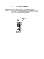
±A [n].[n1-n2]
This command is used to move the motor a specified number of steps, using the value of
an analogue voltage.
The command parameter "n" specifies which Analogue Input (1-6) is used for controlling
the movement. The parameters "n1" and "n2" specify the step interval, where n1 indicates
the number of steps corresponding to an input voltage of 0V, and n2 indicates the number
of steps corresponding to an input voltage of 5.1V. n1 and n2 can be specified from 1 to
65000 steps.
Example :
+A1.100-1000
The above command advances the motor (indicated by +) 100 steps if a voltage of 0V is
applied to Analogue Input 1, and 1000 steps if a voltage of 5.1V is applied. For voltages
between 0V and 5.10V a linear interpolation is used to determine the number of steps
the motor is moved (see figure below).
33
4.4
Motor Commands
The current supplied to a stepper motor can be adjusted to specified values for standby, acceleration/deceleration, and top speed. Normally only a small current is required when the motor is stationary since the
static inertia of a typical stepper motor is much less than the inertia while the motor is rotating, depending on the
speed range of the motor.
The torque of a stepper motor is directly proportional to the applied current, up to the specified phase current
(see the specifications for a given motor).
In the nominal current is exceeded, the motor will overheat and only very little increase in torque will result.
The following 3 commands are used to specify the current supplied to the motor. The commands can be used at
any point in a program. All 3 commands can be specified and changed continuously throughout a program.
If any of the commands is omitted, the respective parameter assumes a default value of 1000mA.
CS [0-6000] (Current Standby)
Determines motor current when the motor is stationary.
CR [0-6000] (Current Ramp)
Determines motor current during acceleration/deceleration.
CT [0-6000] (Current Top)
Determines motor current at maximum speed.
Note that all 3 parameters can only be specified in the range 0 to 3000 mA for Controllers Types
SMC23A/SMC24A/SMC25A/SMC26A (3Amp versions).
Example:
(Program)
.
CS500
Sets motor Standby Current to 500mA (0.5A).
CR6000
Sets motor Ramp Current during acceleration/deceleration to 6000mA (6A).
CT4000
Sets motor Top Current to 4000mA (4A) at top speed.
+100
Advances the motor 100 steps.
CT5500
Sets new motor Top Current to 5500mA (5.5A).
.
.
34
4.4
g+/-
(Velocity Mode)
Motor Commands
The Velocity Mode command is used to move the motor continuously in a
specified direction.
The command is followed by a + or - parameter which specifies the direction of movement.
To stop the motor once the Velocity Mode command has been used, a Z (Smooth Stop) or
K (Kill) command must be used.
If the N (Input Setup) command is used before the g± command, the conditions specified by
the N command can also stop the motor. (See the description of the Input Setup (N) command for further details.)
It should be noted that the Position Counter is updated while the Velocity Mode command
is executed. The command can only be used when it is included in a program.
G+/- [nnnnnnn] The Goto command is used for absolute positioning of a stepper motor.
(Goto)
The specified parameter value refers to the Position Counter and can be specified in the range
-8,388,607 and +8,388,607.
G±A [n].[n1-n2] The Analog Goto command is used for absolute positioning of a motor
(Analog Goto)
motor (similar to the G±[n] (Goto) command) but the required position is determined by the
analogue voltage applied to a specified Analogue Input. The "n" command parameter specifies which Analogue Input (1-6) is used for the control signal. Parameters "n1" and "n2"
specify the required positions corresponding to applied voltages of 0V and 5.10V respectively. The specified position can be set in the range +0 to +65000.
See also the ±A command.
Example:
G±A2.0-800
The above example moves the motor to position +0, if a voltage of 0V is applied to
Analogue Input 2, and to position +800 if the applied voltage is 5.10V.
For applied voltages between 0 and 5.10V a linear interpolation between positions +0
and +800 is made.
H+/-
(Home)
The Home command enables an electrical and mechanical reset of the system to
a pre-defined reference position. As soon as the Controller receives the Home command,
the motor will move in the specified direction (either H+ or H-).
As soon as the EOT (End of Travel) input becomes low, the motor will stop. The motor is
then at its reference position. The speed at which a reset occurs is determined by the S (
Start Rate ) command.
After execution of a Home command, the Position Counter is reset to "+0".
35
4.4
N [n1n2.n3n4]
(Input setup)
Motor Commands
The Input Setup command enables a motor to be started or stopped using control
signals at the User Inputs.
The Input Setup command itself does not start or stop the motor. It only determines how the
next motor command ±[n] / g[±] / G±[n] will be interpreted and executed. Thereafter the Input Setup command is inactive until a new Input Setup command is executed. To subsequently start or stop the motor using the control signal at a User Input, a new Input Setup
command must precede the new motor command.
Command Syntax:
n1: Specifies the User Input (1-3) used to start the motor.
n2: Specifies the User Input (1-3) used to stop the motor.
n3: Refers to n1 in that n3 determines the logic level to be applied to the specified User In-
put in order to start the motor. If n3 is set to 0, the motor will start when logic level 0
is applied to the specified User Input.
If n3 is set to a value between 2 and 9, the start function will be inactive and the
motor will start immediately.
n4: Refers to n2, in that n4 determines the logic level to be applied to the specified User In-
put in order to stop the motor. If n4 is set to 1, the motor will stop when logic level 1
is applied to the specified User Input.
If n4 is set to 0, the motor will stop when the level changes from logic 1 to logic 0.
If n4 is set to a value from 2 to 9, the stop function will be inactive and the motor will
only be stopped a motor command requires it.
(continued on following page)
36
4.4
Motor Commands
(continued)
N [n1n2.n3n4]
(Input setup)
When the Input Setup command is used for a movement sequence, the Position
Counter is updated normally.
While the motor is moving, a Z (Smooth Stop) or K (Kill) command can be used to stop the
motor. Program execution can also be halted using a K (Kill) or Z (Smooth Stop) command
while the Controller is waiting for a start signal from a User Input.
Example 1:
The command N13.01 followed for example by a g+ command will start the motor when
User Input 1 attains a voltage of logic 0. Note that it is a logic level 0, and not a change
from "1" to "0" that activates a start.
The motor will move according to the specified parameters and run at normal speed until a
voltage corresponding to logic "1" is applied to User Input 3. Thereafter the motor will decelerate until it stops, and the next program command is executed.
Example 2:
The command N21.10 followed for example by a +10000 command will start the motor
when User Input 2 is logic "1" and operate at normal speed for 10000 steps (including deceleration ramp), or until a change from logic 1 to logic 0 occurs at User Input 1.
The motor will then decelerate and the next program command is executed.
Example 3:
The command N11.19 followed for example by a G+3500 command will start the motor
when User Input 1 becomes logic "1" and stop when position +3500 is reached. The motor
will operate in accordance with the parameters specified by the R, S and T commands.
37
4.4
Motor Commands
This command enables start/stop control of the motor via control signals at
(Analog Input setup) the analogue inputs. The principle of the Analog Input Setup command is the same as the
Input Setup command, N [n1n2.n3n4].
The 2 command parameters (p1 and p2) specify start and stop conditions respectively.
The Analog Input Setup command itself does not start or stop the motor. It only influences how the next motor command ±[n] / g[±] / G±[n] will be interpreted and executed.
Thereafter the command is inactive. To subsequently start the motor again using control
signals at an Analogue Input, a new Analog Input Setup command must precede the
new motor command.
The complete syntax for the Analog Input Setup command is as follows:
NA [p1.p2]
p1:
If the start conditions are fulfilled, the motor is started. If p1 is assigned the character X, an unconditional start is defined, and the motor will start immediately
the motor command is executed.
p2:
If the stop conditions are fulfilled, the motor will be stopped. If p2 is assigned the
character X, an unconditional stop is defined and the motor will operate until the
specified motor command (±[n], g±, G±[n]) requires it to stop.
a1:
Specifies the Input used for the start control signal. a1 can be specified in the
range A1 to A6, corresponding to Analogue Inputs 1-6.
a2:
Specifies the Input used for the stop control signal. a2 can be specified in the
range A1 to A6, corresponding to Analogue Inputs 1-6.
n1:
Specifies the Start Reference Value. The Reference Value is compared with the
measured voltage at the specified start Input (a1). The Start Reference Value
can be set in the range 0 to 255.
n2:
Specifies the Stop Reference Value. The Reference Value is compared with the
measured voltage at the specified stop Input (a2). The Stop Reference Value
can be set in the range 0 to 255.
m:
The operator for comparison between the Reference Value and the measured
value at the input(s). To start/stop the motor when the voltage at the respective
analogue input is less than the Reference Value, the operator should be specified as "<". To start/stop the motor when the applied voltage is greater than the
Reference Value, the ">" operator is specified.
38
4.4
(continued)
NA [p1.p2]
(Analog Input setup)
Motor Commands
Since n1 and n2 are specified as values in the range 0-255 and the voltage
measured at the Analogue Inputs is in the range 0-5.10V, a conversion must
be made when specifying n1 and n2, either by converting the Reference values to a
voltage or vice versa. The conversion is made as follows:
Vref = 0.02 x n
or
n = 50 x Vref
Example:
If a Reference Value of 1.20V is required, n should be specified as:
n = 50 x 1.2 = 60
Program Example 1:
.
.
NAA1<60.A6>100
+10000
.
In the above program example, the motor is started if the applied voltage at Analogue Input 1 is less than 1.2 Volts (see conversion example above). Otherwise
nothing occurs. When the motor is running, it is stopped either after completion of
the 10000 steps or when the voltage at Analogue Input 6 is greater than or equal to
2V (n2=100).
Program Example 2:
.
.
NAX.A5>220
G+100000
.
The parameter specification X indicates that the start condition is inactive and the
motor will therefore start immediately. Thereafter the motor will stop when position
+100000 is reached or if the applied voltage at Analogue Input 5 is greater than or
equal to 4.4V (n2=220).
ÄÄÄÄÄÄÄÄÄÄÄÄÄÄÄÄÄÄÄÄÄÄÄÄÄÄÄ
The K (Kill) and Z (Smooth Stop) commands can be used to interrupt program execution.
39
4.4
Motor Commands
In contrast to a normal DC motor (which is "Self-commutating"), a stepper motor is electrically commutated. That
is, a stepper motor is driven by magnetic fields which are controlled electronically. When the motor is loaded, the
magnetic fields will eventually not be powerful enough to continue to turn the rotor. The motor will stop, but the
electronics will continue to move the magnetic fields at the same speed. It is therefore important that a motor is
accelerated and decelerated at appropriate rates, in order for the magnetic fields to drive the rotor.
Similarly a stepper motor has a maximum speed and if this is exceeded the motor can no longer provide the same power and will simply stop.
There are 3 basic parameters which should be considered:
S [16-2000] (Start Rate steps/second)
The Start Rate is the speed at which the motor is started. If it is set too high, the motor will simply stop at an
arbitrary position. The Start Rate can be set in the range 16 to 2000 steps/second. The default Start Rate is
100 steps/second.
T [16-15000] (Top Rate steps/second)
The Top Rate specifies the maximum speed of the motor. If it is set too high, the motor will be unable to provide enough power and will stop at an arbitrary position. The Top Rate can be set in the range 16 to 15000
steps/second. The default Top Rate is 1000 steps/second.
R [1-10000] (Ramp) / RT [1-1000] (Ramp time) / RS [10-30000] (Ramp slope)
This value specifies how the motor is accelerated and decelerated. The value can be specified in 1 of 3
forms. R (Ramp) is used if the required acceleration/deceleration is specified in steps. RT (Ramp Time) is
used if the required acceleration/deceleration is specified in terms of time, and RS (Ramp Slope) is used if
the required acceleration/deceleration is specified in steps/second². Ramp Slope can be used advantageously if the Top Rate or Start Rate are repeatedly changed in a program, since the acceleration per unit of time remains the same. If too high an acceleration/deceleration rate is selected, the motor will stop.
R [n] can be specified in the range 1 to 10000 steps. The default Ramp is 100 steps.
RT [n] can be specified in the range 1 to 1000, corresponding to a range from 0.01 to 10 seconds.
RS [n] can be specified in the range 10 to 30000 steps/second².
Examples:
R100 specifies an acceleration/deceleration of 100 steps. RT50 results in an acceleration/deceleration time
of 0.5 seconds. RS900 gives an acceleration/deceleration rate of 900 steps/second².
All 3 parameters must be specified in a program and can be adjusted at any point in the program. If T (Top Rate)
is set to a value less than S (Start Rate), the motor will operate at the Top Rate specified by T without accelerating or decelerating.
40
4.4
r [n1.n2]
Motor Commands
These 3 commands are used to determine the motor parameters R, S
(A/D Ramp Step)and T using the analogue voltage applied at one of the 6 Analogue Inputs.
s [n1.n2]
The r [n1.n2] command determines the Ramp Step parameter.
(A/D Start Rate) The s [n1.n2] command determines the Start Rate parameter
The t [n1.n2] command determines the Top Rate parameter.
t [n1.n2]
(A/D Top Rate)
n1 specifies the Analogue Input used for controlling a given step/frequency. n1 can be specified in the range 1-6 corresponding to the required Analogue Input 1 to 6. The voltage applied to the specified input must be in the range 0 to 5.10V.
n2 specifies the value corresponding to full-scale input voltage (5.10V) either in terms of
steps for the r [n1.n2] command, or in terms of frequency for the s [n1.n2] or t [n1.n2] command.
n2 can be specified as a value in the range 1 to 10 according to the following table for
Ramp, Start Rate and Top Rate.
A voltage of 0V at a specified Analogue Input always corresponds to either 16 steps for the
r [n1.n2] command, or 16 steps/second for the s [n1.n2] or t [n1.n2] commands.
The VR, VS and VT commands can be used to verify current parameter settings. See the
description of these commands for further details.
(continued on following page)
41
4.4
Motor Commands
(continued)
Example:
r [n1.n2]
(A/D Ramp Step)
The command t1.4 is used in a program. When the program is executed, the
Controller measures a voltage of 2.5V at Analog Input 1 (AN1). This voltage is converted to
a frequency of:
s [n1.n2]
(A/D Start Rate)
2.5 x 4000
= 1960 Hz = 1960 steps/second
5.10
t [n1.n2]
(A/D Top Rate)
This frequency is then used for the next motor movement. The specified value of n2 in
the example results in 0V corresponding to a frequency of 16Hz and full-scale 5.10V
corresponding to 4000Hz.
VR
(Verify Ramp)
The Verify Ramp, Verify Start Rate, and Verify Top Rate commands can be
used to verify the current values of the motor parameters R, S and T.
VR returns the value of the Ramp Step "R" in steps. VS returns the value of the
VS
(Verify Start Rate)
VT
(Verify Top Rate)
Start Rate "S" in steps/second. VT returns the value of the Top Rate
in steps/second.
Example:
A verification of the current Top Rate is required. The following command string is therefore
sent to the Controller:
VT (carriage return)
The Controller responds:
T1000 (carriage return)
Indicating the current Top Rate is 1000 steps/second.
VR, VS and VT can also be used to check the value of the motor parameters determined by the r [n1.n2] , s [n1.n2] and t [n1.n2] commands.
42
4.5
A [1-3]
User Interface Commands
The Activate Output command sets a specified User Output to logic "1".
(Activate Output) The command character is followed by a parameter value of 1 to 3 which specifies which output is to be activated.
Example: A2 sets Output 2 to logic "1".
C [1-3]
(Clear Output)
The Clear Output command sets a specified User Output to logic "0".
The command character is followed by a parameter value of 1 to 3 which specifies, which
output is de-activated.
Example: C1 sets Output 1 to logic "0".
U [1-3]
The Until command is used to repeat a program segment until logic "0" is applied
U [A1-A6]
to a specified input (see Electrical Specifications).
(Until)
Either the entire program or only a specified segment can be repeated. The User Inputs are
specified by the parameter values 1 to 3. The Analogue Inputs are specified by the parameter values A1 to A6.
e.g.:
.
.
.
G+50
A2
*
U3
-
Repeats program segment from the beginning until logic
"0" is applied to User Input 3.
A1
D25
C1
**
UA1
-
Repeats program segment between * and **, until logic "0"
is applied to Analogue Input 1.
.
.
.
43
4.5
User Interface Commands
V2
The Verify I/O command enables the status of User Inputs and Outputs to be
(Verify I/O)
determined. When the V2 command is sent to the Controller, it responds with a V followed
by two parameter values between 0 and 7.
The first parameter indicates the voltage levels at the User Inputs. The second parameter
indicates the voltage levels at the User Outputs.
The status of the Inputs and Outputs is determined from the returned parameters according
to the following table:
Example:
The Verify I/O query returns a response V25, which indicates that Input 2 is logic "1", and
Outputs 1 and 3 are logic "1".
The Verify I/O command is used exclusively when there is a constant interface connection
between a computer/terminal and the Controller. It cannot be used in a program.
VA [1-6]
The Verify AInput command is used to determine the voltage at a specified
(Verify ainput)
AnalogueInput. 8-bit resolution is used for the measurement, which results in the measured
value being given in 20mV steps with 5.10V as the maximum value. The Verify AInput
command can be used when the Controller is in Standby Mode. The 3 User Inputs can, for
example, be connected to 3 Analogue Inputs and thus verify that the voltages are as expected.
44
4.5
VA
(Verify ainput)
User Interface Commands
The Verify AInput returns the digital levels at the Analogue Inputs. The response
string has the following format:
Example:
The command string "VA" is sent to the Controller.
The following response is returned:
VA101001 (Carriage return)
indicating that Analogue Inputs 1, 3, and 6 are logic 1 (>2.5V), and Analogue Inputs 2, 4,
and 5 are logic "0" (<2.5V).
W [1-3]
The Wait For command stops program execution until logic "1" is applied to a
W [A1-A6]
specified input. If the command character is followed by a number from 1 to 3,
(Wait For)
the specified input is one of the 3 User Inputs. If the command parameter is A1 to A6, the specified input is one of the 6 Analogue Inputs.
Example:
.
.
A3
G+372
W1
-
Pauses program execution until User Input 1 is logic "1".
G+46
C1
D20
WA5
-
Pauses program execution until Analogue Input 5 is logic "1".
.
.
45
4.6
Flow Control Commands
D [1-32000]
The Delay command pauses program execution. The command character must be
(Delay)
followed by a parameter value between 1 and 32000 which specifies the Delay duration in
1/100 second.
Example:
D27
DA[n].[n1-n2]
(Analog delay)
-
results in a delay of 0.27 seconds.
The Analog Delay command is used to set a delay in program execution
which is determined by one of the Analogue Inputs and can vary from 0.01 to 320 seconds.
Command Format:
Specifies which Analogue Input is used to control the delay.
n:
n1-n2: Specify the required delay duration. n1 is the lower limit and corresponds to the de-
lay when a voltage of 0V is applied to the specified input. n2 is the upper limit
and corresponds to the delay when a voltage of 5.10V is applied.
Example:
DA2.10-100
-
Enables a delay of between 0.1 and 1.0 seconds, controlled by a voltage
of between 0 and 5.10V applied to Analogue Input 2.
J [n1]
The Jump command is used to make an unconditional jump to a specified line
(Jump)
number in the program.
The program line number "n1" can be specified in the range 0-255.
Example:
Line no.:
0
A1
1
+1000
2
A2
3
G+5
4
C2
5
J2
The Jump command at line 5 in the above example causes the A2 , G+5 , and C2 commands (lines 2 to 4) to be continuously repeated. The program can only be interrupted
using the Z (Smooth Stop) or K (Kill) command.
46
4.6
Flow Control Commands
JC [0-7].[0-255]
In contrast to the J (Jump) command, the JC (Jump Conditional) command is used
(Jump Cond.)
to make a conditional jump to a specified line number in a program, depending on the levels at
all 3 User Inputs. The line number can be specified in the range 0-255. The condition for
the jump to occur is specified according to the following table:
Example:
The command JC5.10 results in a jump to program line 10 if User Inputs 1 and 3 are logic
"1".
Example:
Line no.:
0
S450
1
R200
2
A1
3
+1200
4
JC5.4
5
G+0
6
C1
7
JC3.2
-
Jumps to line 4 if User Inputs 1 and 3 are logic "1".
-
Jumps to line 2 if User Inputs 1 and 2 are logic "1".
47
4.6
Flow Control Commands
JC [p].[n1]
This conditional jump command is similar to JC[0-7] - if an input level condition
(Jump con.)
is fulfilled, a jump is made to a specified program line. In contrast to the JC[0-7] command
however, the JC[p] jump condition is determined by the level at a specific Input and not by
the pattern at all 3 User Inputs.
The JC[p] command can be used both with User Input levels and with the Analogue Inputs.
Command Format:
JC [i]=[n].[n1]
Specifies the input used for the jump condition.
i:
A value of "i" between 1 and 3 specifies the corresponding User Input 1 to 3. A value
of "i" between A1 and A6 specifies the corresponding Analogue Input 1 to 6.
Specifies the Reference Level to be compared with the measured level at the speci-
n:
fied input. n can assigned a value of 0 or 1. If the level at the specified input is equal
to the Reference Level, the jump is made.
n1: Specifies the program line to jump to if the jump condition is fulfilled.
Program Example:
Line no.:
0
S750
1
R700
2
C3
3
+500
4
JC2=0.3
5
G+0
6
T1000
7
A2
8
JCA4=1.5
-
Jumps to line 3 if User Input 2 is logic "0".
-
Jumps to line 5 if Analogue Input 4 is logic "1".
When the Analogue Inputs are used as logic inputs, logic "1" corresponds to voltages greater than or equal to 2.5V, and logic "0" corresponds to voltages less than 2.5V.
48
4.6
Flow Control Commands
JCA [p].[n1]
This conditional jump command is similar to the JC command - if the level at a
(Jump Cond.)
specified input fulfils the jump condition, a jump is made to the specified program line.
In contrast to the JC command however, the JCA jump condition is determined by an analogue voltage level at one of the Analogue Inputs 1 to 6, and not by a logic level.
Command Format:
JCA [a1mn].[n2]
a1: Specifies the Analogue Input used for evaluating the jump condition.
mn:
Specifies the Reference Level (n) with which the measured input voltage is compared and the operator for the comparison (m).
If "m" is specified as ">", the jump is made if the measured input voltage is greater
than or equal to the Reference Value. If m is specified as "<", the jump is made if the
measured voltage is less than the Reference Value.
The Reference Level "n" can be specified in the range 0 to 255.
n1: Specifies the program line number to jump to if the jump condition is fulfilled.
Since n is specified as a value in the range 0-255 and the measured voltage is a value in
the range 0 to 5.10V, a conversion of voltage to a valid Reference Level value must be made when specifying the jump condition. The conversion is made as follows:
Vref = 0.02 x n
or
n = 50 x Vref
Example:
A Reference Value of 3.00V is required.
n = 50 x 3.00 = 150
Program Example:
Line no.:
0
S450
1
R600
2
D2
3
+342
4
JCA3>150.2
5
G+0
-
Jumps to program line 2 if the voltage at Analogue Input 3 is
greater than or equal to 3.00V.
49
4.6
Flow Control Commands
JS [n1]
In contrast to the J (Jump) command which jumps to a specified program line
(Jump Sub.)
number,the JS (Jump Sub) command makes an unconditional jump to a program subroutine.
When a JS command is executed, the Controller first stores the number of the next line
after the JS command and then jumps to the line number specified by the JS command.
When the RET (Return) command is encountered in the sub-routine, the program returns
to the main program at the line immediately after the JS command and continues execution
from there.
The JS command be used up to 32 times in a program, corresponding to 32 nested subroutines.
L [0-255]
The Loop command is used to repeat execution of a specified program segment.
(Loop)
The command parameter specifies the number of times the Loop is executed and can be
specified in the range 1 to 255. The segment to be repeated must be delimited by a pair of
Loop commands such as L0 and L5, as illustrated in the following example.
Example:.
L0
.
.
.
(Program)
.
.
.
L5
.
The program segment between L0 and L5 will be repeated 5 times. If the initial Loop delimiter L0 is omitted, the entire program will be repeated from line 1.
50
4.7
Extended Command Set
(Types SMC23/24 only)
The following pages describe the Extended Command Set available only with Stepper Motor Controllers Types
SMC23 or SMC24. Note that the Q (Query) command is not implemented in Controller
SMC24.
51
Types SMC23 and
4.7
Extended Command Set
(Types SMC23/24 only)
Register description.
Types SMC23 and SMC24 are equipped with 510 User Storage Registers which can be used for storing intermediate results, etc. These are designated R1 - R510. In addition, the Controllers are equipped with 7 predefined
registers which can only be used for specific purposes. Register T for example is used to determine the motor
Top Rate. The user- and predefined registers enable parameters such as lengths, speeds, acceleration, delay
times, program loops, etc., to be continuously changed and controlled during program execution.
In addition, the User Register contents can also be stored permanently in the Controller's EEPROM memory. For
example, parameters which have been set via Keyboard/Display Module KDM10 can thus be stored permanently
in the Controller and recalled when the system is started up.
The following registers are available in Types SMC23 and SMC24:
R :
Predefined register for the number of steps used to accelerate/decelerate the motor (Ramp). Note
that this register is completely independent of, and should not be confused with, User Registers R1
to R510.
S :
Predefined register for Start Rate.
T :
Predefined register for Top Rate.
D :
Predefined register for program Delay.
L :
Predefined register for program Loop Counter.
n :
Predefined register for Position Counter in steps.
A1-A6 :
Predefined registers for Analogue Inputs' level from 0-255 corresponding to voltages from 0-5.10V.
R1-R510 : 510 User Registers for intermediate results, etc.
Example 1:
R2 = 3000
; Sets the value of register R2 to 3000
T = R2 + 100
; Sets the Top Rate to 3100 steps/second for the next motor
; operation.
Example 2:
R34 = 400
D = R34 + A1
; Waits (400 + A/D conversion of Analogue Input 1 level) x 10ms
R1 = n + R2
; Sets the value of R1 to value of the Position Counter in steps + R2
R1 = 350 + 700
; Sets the value of R1 to 1050
+(R1)
; Advance the motor 1050 steps.
R30 = 100
; Sets the value of R30 to 100
R31 = 200
; Sets the value of R31 to 200
R34 = R30 + R31
; Sets the value of R34 to value of R30+R31
G+(R34)
; Goto (move motor to) position R34
Example 3:
Example 4:
Example 5:
52
4.7
Extended Command Set
(Types SMC23/24 only)
In addition, register arrays can be defined by using one register to point to the contents of other registers. This
enables, for example, the contents of a block of registers to be copied to a different array.
Example 6:
The contents of ARRAY1 (registers 100-199) are copied to ARRAY2 (registers 300-399)
R1=100
; Set Array 1 pointer
R2=300
; Set Array 2 pointer
L0
; Loop delimiter for copying 100 registers
R(R2)=R(R1) ; Copy contents of a register in array1 to register in array2
R1=R1+1
; Increment the Array 1 pointer to the next register
R2=R2+1
; Increment the Array 2 pointer to the next register
L99
; Repeat Loop until the contents of all 100 registers have been copied.
53
4.7
Extended Command Set
(Types SMC23/24 only)
Rules for Register Operations:
1: An "is equal to" sign "=" is used to assign the contents of a register. A maximum of 3 registers may be
used in an assignment expression:
e.g. R3=R23+T is legal, but R3=R23+T-100 is illegal.
2: The following 4 arithmetic operators can be used in register operations:
+ : Addition
-
: Subtraction
*
: Multiplication
/
: Division
3: All values and register contents must be integers in the range 0 to 65535. For division however, all operands must be max. 32767 or an error will result.
4: The result of division is always rounded down.
Example:
R2=289/10
; Calculates the result of 289 divided by 10.
PRINT(5.R2) ; The result is rounded down, the printed result is 28.
5: The R, S, T, L and D registers can be assigned values using an "equals" sign, but a quicker method, both
in terms of programming and at run-time, is to assign values directly to these registers. If the required value is known and a constant, it can be directly assigned to the register.
Example:
T2000 is equivalent to T=2000
D200 is equivalent to D=200
S500 is equivalent to S=500
6: When "if" expressions are used for numeric comparison, the values to be compared must be maximum
32767. This is valid both for register contents and numeric values.
54
4.7
VR[0-510]
(Verify)
Extended Command Set
(Types SMC23/24 only)
The Verify Register command is used to verify the contents of a register.
SMC23A / SMC23B / SMC24A / SMC24B contain extended memory and there are 510 user
registers that can be verified.
Example:
VR9
; Returns the contents of register R9.
I[5-7]
The Initialize command is used to save or recall the contents of all user registers
(Initialize)
to or from the Controller's permanent EEPROM memory. The command is also used to reset (erase) all user register contents.
The Initialize command can be used both in Standby Mode and Programming Mode.
Example:
I5
;
Resets (erases the contents) of all User Registers.
I6
;
Stores the contents of all 510 User registers in EEPROM.
;
The predefined registers (R,S,T etc,) are not stored in EEPROM
;
Recalls the contents of all 510 User Registers from EEPROM.
I7
55
4.7
con=n
Extended Command Set
(Types SMC23/24 only)
The Conversion command is used to set a conversion factor between the number of steps a
motor moves and a unit of measurement such as length, volume, position, etc. "n" specifies
the number of steps per unit length, volume (mm, ml, cm, dl, etc). The conversion factor can
be specified as a real number in the range 0.0001 to 1600.0000, with up to 4 decimal points.
The conversion factor command is inserted at the beginning of a program and stays in effect
until any subsequent conversion factor is specified at run-time. When a motor operation is
performed, the number of units specified by the motor command is multiplied by the conversion factor and the motor moves the resulting number of steps.
If, for example, a motor must move 2.3456 steps to dose a volume of 1 millilitre, the conversion factor is set to a value of 2.3456 using the command con=2.3456. To dose a volume of
450 ml in a subsequent motor command, the value 450 is specified. The conversion results
in 450 * 2.3456 (1055.52) steps. The motor will then move 1055 steps and the remainder
(0.52 steps) will be stored. The remainder is used in the next motor operation to correct for
the 0.52 dosage steps.
Example:
A system requires motor operation of 14.654 steps to dose a volume of 1 ml.
con=14.654
;
The conversion factor is set to 14.654 steps per millilitre.
R1=290
;
A value of 290 is assigned to register R1.
+(R1)
;
The motor is moved to provide a dose of 290 ml.
;
The number of steps run is 290 * 14.654=4249. The step
;
remainder is 0.66
D100
;
Delay of 1 second.
+18
;
Dose 18 ml. The number of steps is
;
18*14.654+step_remainder=264.
;
The new step remainder is 0.432
Note that after a "Home" operation using the H command, the step remainder is reset to 0
since the motor is set to its absolute reference point.
56
4.7
PRINTn1.n2.n3
Extended Command Set
(Types SM C23/24 only)
The Print command is used to print out the contents of registers to external modules. At present, print-out to 4 external modules is possible: to a PC via the RS232 interface and to
DIS10, KDM10 and IOM10 Modules via the RS485 interface.
Command Format :
n1 :
Specifies the address of the module to be printed to (1-31). Address 255 is reserved
for a PC.
n2 :
Specifies the register or cursor position to be printed to in the external module.
n3 :
Specifies the register, numeric value or text string in the Controller to be printed.
Example 1:
PRINT1.0.R23
Prints the contents of register R23 to the module whose interface address is 1. Since transmission via the RS485 interface is balanced, it is possible to locate external modules up to 500
metres from the Controller.
Example 2:
PRINT255.0.R2
Prints the contents of register R2 to a PC via the RS232 interface. Address 255 is reserved
as the address for PCs. Note that the Print command can be used to print out register contents at run-time. It is especially well-suited for debugging a program. If JVL's "Editor2" program is used, once the Controller program has been transferred using the F5 function key,
the F6 function key can be used to switch to the communication window where register
contents will be displayed when a Print command is executed at run-time.
Example 3:
PRINT3.41."Key in Value: "
When a Keyboard-Display Module KDM10 is incorporated in a system, it is often desirable
to display information to the user. The above example illustrates how text can be written to
the module's LCD display. In the example, the address of the module is 3. The second parameter value is cursor position 41, which is the first character on line 2 of the display.
57
4.7
Extended Command Set
(Types SMC23/24 only)
Example 4:
R1=5555
;
Assign a value of 5555 to register R1
R30=333
;
Assign a value of 333 to register R30
PRINT5.41.R1
;
Print the contents of register R1 to cursor position 41 of a KDM10
PRINT2.0.R30
;
module with address 5
Print the contents of register R30 to the display of a DIS10 module
with address 2.
When external modules DIS10 or KDM10 are used in a system, it is often necessary to print
out the contents of register on the displays of the modules. As illustrated in the above example, this is best accomplished using the PRINT command to print the contents of a register either to a cursor position or directly to the LED display of the DIS10 module.
58
4.7
IF [p1 m p2]
Extended Command Set
(Types SMC23/24 only)
The IF command is used for comparison of 2 numeric values, p1 and p2. These values may
be the contents of registers such as R1, A1, T etc., or simply integer values such as 10500,
420, etc. All registers described in the "Register Description" section at the beginning of this
Chapter can be used in IF expressions. The comparison operator "m" may be one of the
following :
m
Condition fulfilled if:
<
>
=
<=
>=
<>
Less than
Greater than
Equal to
Less than or equal to
Greater than or equal to
Not equal to
If the condition specified by the IF expression is fulfilled, the next line of the program is executed. If the condition is not fulfilled, the next line is omitted and execution continues from
there.
Example 1:
:START
IF R10 < 9800
; If the content of register R10 is less than
J:PROG1
; 9800, jump to label PROG1.
J:PROG2
; else jump to label PROG2.
Example 2:
T=100
:START
; Set Top Rate to 100 steps/second
T=T+50
; Increase Top Rate by 50
IF T>4000
; If the Top Rate is greater than 4000 steps/s
J:SPEEDOK ; Jump to label SPEEDOK
+1000
; else move 1000 steps clockwise
J:START
; Jump to label START, where the speed is increased
The above program moves the motor 1000 steps at a speed of 150 steps/second and increases the Top Rate by 50 steps/second until a Top Rate of 4000 steps/second is reached.
59
4.7
INPUTn1.n2
Extended Command Set
(Types SMC23/24 only)
The INPUT command is used to read-in data from external modules connected to the RS485
interface. It can be used to read-in data from modules such a Keyboard, Display, thumbwheel, BCD data from PLC equipment, printer, extra inputs, digital-to-analogue modules,
etc.
All of the above-mentioned external modules are intelligent and will therefore contain registers whose contents can be read into the Controller's registers using the INPUT command.
The size and number of registers in external modules may vary, but each module has at least 1 register.
Command Format :
n1: Specifies the address of the external module from which input is required. The address
parameter must be specified as a value between 0 and 31. The RS485 interface
enables up to 32 modules to be connected to the interface. The address of each module must be set via DIP switches on the individual module.
n2: Specifies the register in the external module from which input is to be read. n2 must be
specified in the range 0-255.
Example 1:
An IOM10 module has 16 inputs and 8 outputs are used. The Module address is 5. All 16
inputs are to be read and tested to determine if the value is 255. If this is the case, the module Counter is read and the program continues.
In the instruction manual for the IOM10 module, the Counter register is specified as register
2 and the register for all 16 inputs is 3.
:READINP
R10=INPUT5.2
; Read all 16 inputs and transfer contents
; to R10.
IF R10=255
; If inputs not equal to 255 read again
J:READ_COUNTER
J:READINP
; else read Counter value and continue
; program
:READ_COUNTER R30=INPUT5.3
R(R1)=R30
; Read Counter and transfer to R30
; Transfer Counter value to an array
; register using R1 as array pointer.
60
4.7
Extended Command Set
(Types SMC23/24 only)
AO[a].[o]
The Activate command is used to activate a flag in an external module whose address
(Activate)
is specified by "a".
The Flag number is specified by "o". For example, the flag may refer to an output on a IOM10
module. When the flag is activated, an output will be activated. A flag in a different module may
refer to a completely different function. For example if flag 3 in a KDM10 module is activated,
the cursor on the module's LCD display will blink. Flags with the same number in different modules can have different functions. See the instruction manual for the individual module for a
description of the function of the module's flags.
Format:
AO{1<=a<=31}.{1<=o<=255}
Example 1:
A Keyboard-Display Module has address 4. The module display is to be erased so that new text
can be displayed. The following command will erase the display and position the cursor at the
top left-hand corner of the display.
AO4.1 ; Erase LCD display
Example 2:
An IOM10 module and SMC23/24 are connected together in a system. The IOM10 module address is 10. Output 4 is to be activated. The following command is used:
AO10.4
61
4.7
CO[a].[o]
(Clear)
Extended Command Set
(Types SMC23/24 only)
The Clear command is used to clear a flag in an external module. The number of flags
which that can be cleared in different external modules varies, but each module has at least 1
flag. For the KDM10 module (Keyboard-Display Module) for example, the Clear command can
be used to clear the LCD display; in the IOM10 module (I/O module) the Clear command can be
used to deactivate one of the module's outputs, etc.
Format:
CO {1<=a<=31}.{1<=o<=255}
Example 1:
Controller Type SMC23 and a KDM10 module are connected in a system via the RS485 interface. The address of the SMC23 is 1 and the KDM10 module address is 3. The Cursor on the
KDM10's LCD display is to be switched off. If the cursor is active while text is being printed
using the PRINT command, the display may flicker. This is avoided by switching off the cursor
as follows:
CO3.3 ; Deactivate cursor
Example 2:
Controller Type SMC23 and an IOM10 module are connected in a system via the RS485 interface. The IOM10 module's address is 5. The IOM10's output 7 is to be deactivated. The command is as follows:
CO5.7 ; Deactivate output 7 on IOM10 module with address 5.
62
5.1
Electrical Specifications
Min.
Typical
Max.
45
4
V DC
Units
Power Supply (Types SMC 23/25):
Supply voltage
Power Consumption
(unloaded, no motor)
15
W
Power Supply (Types SMC24/26):
Supply Voltage (Nom. 230V)
Supply Voltage (Nom. 115V)
Power Consumption
(unloaded, no motor)
User Supply :
Output Voltage (adjustable)
Rated Current
207
100
242
125
VAC
VAC
W
5.1
30.2
500
V DC
mA DC
0.2
15
3/(6)
45
A DC
V DC
kHz
-12
12
-12
12
9600
* 500
V
V
V
V
Baud
V (Max.)
10
Motor Driver :
Output Current (per phase)
Output Voltage
Chopper Frequency
22
Interface :
Rx mark position
Rx space position
Tx mark position
Tx space position
Communication Rate
Isolation Voltage
-1
2.5
-3
5
110
Module Interface (SMC23/24):
Communication Distance 0
Communication Rate
Isolation Voltage
500
50
m
* 500
kbit/sec
V (Max.)
32
10
20
45
>2.7
>6.5
>16.2
kohm
V DC
mA DC
VDC
-
User Inputs 1 -3 & Stop Input:
Input Impedance
Supply :
Voltage
Current
Logic "0"
Logic "1"
*
()
at 5V
at 12V
at 30V
at 5V
at 12V
at 30V
at 5V
at 12V
at 30V
10
5
<1.7
<3.0
<6.7
-
Measured from Supply ground to Interface ground
Values valid for Type SMCxxB.
(Continued on following page)
63
5.1
Electrical Specifications
Min.
Typical
Max.
Units
8
** 45
5.10
±1
±1
±½
>2.5
Bit
V DC
V DC
LSB
LSB
LSB
V DC
-
3.3
3.5
V DC
kOhm
V DC
30
V DC
Analog Inputs :
Resolution
Input Voltage (Max allowable)
Input Voltage (Nominal)
Offset Error
Gain Error
Temperature Drift @ 0-50°C
Logic "0"
Logic "1"
-20
0.00
<2.5
-
±½
±½
±¼
CW/CCW Inputs (SMC23/24):
Input Impedance
Logic "0" (active)
Logic "1" (inactive)
2.4
(-30)
3.0
30
User Outputs :
Supply Voltage
Rated Output Current per output
°
1 output activated @25 C
°
2 outputs activated @25 C
°
3 outputs activated @25 C
5
Operating Temperature Range :
0
**
700
460
300
mA DC
mA DC
mA DC
50
Absolute max. time < 1 sec.
64
°
C
5.2
Physical Dimensions
(Types SMC23 and SMC25)
If the Controller is mounted in a closed cabinet, a ventilation fan or other form of cooling should be installed. The
Controller is however protected against overheating by a built-in thermo-switch which disconnects the driver stages at a temperature of approximately 80 °C.
65
5.2
Physical Dimensions
(Types SMC24 and SMC26)
If the Controller is mounted in a closed cabinet, a ventilation fan or other form of cooling should be installed. The
Controller is however protected against overheating by a built-in thermo-switch which disconnects the driver stages at a temperature of approximately 80°C.
66
5.3
Memory Utilization
The permanent memory of the Controller consists of a E²PROM. The memory is 0.5 kbyte (512 bytes) in SMC25,
SMC26, and 8kbyte in SMC23, SMC24.
4 bytes are used to correct the A/D converter offset-error and for adjustment of the Controller's thermometer
function (TP).
In order to enable optimum utilization of the available memory, the following table gives the memory requirements of each program command. The total size of a program must not exceed 508 bytes in SMC25/26 and
7500 bytes in SMC23/24.
If an attempt to store a program greater than 508/7500 bytes is made, the Controller will issue an error message
"E3".
1 byte :
g±
H±
RET
(Blank line)
5 bytes : con=[nnnn.nnnn]
C[n]
I[n]
r,s,t[n.n]
U[n]
W[n]
L[nnn]
J[nnn]
JS[nnn]
7 bytes : NA[p1-p2]
6 bytes : DA[n].[n1-n2]
±A[n].[n1-n2]
G±A[n].[n1-n2]
2 bytes : A[n]
3 bytes : AO[n.n]
CO[n.n]
CR[nnnn]
CS[nnnn]
CT[nnnn]
R[nnnnn]
RS[nnnn]
RT[nnnnn]
S[nnnn]
T[nnnn]
N[nn.nn]
D [nnnnn]
4 bytes : f [±nnnnnnn]
± [nnnnnnn]
G [±nnnnnnn]
JC[n.nnn]
JCA[p].[n1]
67
10 bytes :
PRINT(typ.)
R[n]=x
12 bytes :
INPUT[n.n.n]
14 bytes :
R[n]=x+x
17 bytes :
IF(max.)
5.4
Connectorboard for the controller
68
5.5
Motor Connections
69
5.6 Application Example for Controller Type SMC25
The following example illustrates how 2 Controllers
This is important because the inductive sensors
can be used for motion control of an X-Y Table. The
determine the reference points for the X and Y axes
Table is used to drill 2 holes in an aluminium block.
and thus the accuracy of the entire system. A sen-
Two stepper motors are mounted. In addition, an
sor with a gauge distance of 1mm will typically re-
inductive sensor is used for each axis to register
sult in a repetition accuracy of ±1/100mm, which
when the respective axis has reached its mechani-
should be sufficient for the majority of applications.
cal reference position (0 position). The feeler gauge
The drill itself is not described here, but could for e-
distance should be as small as possible (typically
xample consist of a DC motor vertically driven by a
1-2mm) since it greatly determines the repetition
hydraulic/pneumatic cylinder.
accuracy.
70
5.6
Application Example for Controller Type SMC25
Electrical Connections.
Before the actual task of programming the Controllers is started, it is recommended that the input and output
signals of the system are clearly defined.
A Start button is connected to the Y-axis controller to start the system.
The following elements must be handled by the system:
1) 2 Stepper motors.
2) 2 Inductive Sensors with NPN outputs (0V at the output when activated).
3) A drill which is activated by a voltage pulse of 0.1 second duration. The drill outputs 12V when the holes
have been drilled and the drill unit has returned to its start position.
4) A Start button.
5) Internal synchronisation signals between the 2 Controllers. (See program description.)
The following page illustrates the electrical connection of the system.
The Controllers' User Outputs and Inputs are used in the following manner:
X-Controller.
Y-Controller.
Input 1
Input 1
Used to receive "ready" signal from the
Used to receive "ready" signal from the
Y-controller.
X-controller.
Input 2
Input 2
Used to receive "ready" signal from the drill.
Used for the Start button.
Input 3
Input 3
Inductive Sensor (X-axis)
Inductive Sensor (Y-axis).
Output 1
Output 1
Used to send "ready" signal to the Y-controller.
Used to send "ready" signal to the X-controller.
Output 2
Output 2
Used to send start impulse to the drill.
Not used.
Output 3
Output 3
Not used.
Not used.
71
5.6
Application Example for Controller Type SMC25
See Chapter 2 for the locations of individual connectors.
72
5.6
Application Example for Controller Type SMC25
Program for Control of the Drilling Application.
Before programming is started, the values of all parameters should be defined.
Holes are to be drilled in the aluminium block at the following coordinates:
Hole 1 - 4013,7387
Hole 2 - 5164,1949
The coordinates are specified in steps relative to the reference point of the inductive sensors.
The drill unit is activated by a voltage impulse of 0.1s duration. Once the holes have been drilled, the drill unit
moves to its start position and outputs a constant voltage of 12V to indicate that the drilling operation is complete.
The sequence of instructions to be programmed for the application can be described as follows:
1. If the start button is activated, continue to point 2.
2. Go to position 4013,7387
3. Drill hole
4. Go to position 5164,1949
5. Drill hole
6. End, Go to point 1
If this procedure is followed, the system will wait until the start button is activated, drill 2 holes and wait until the
start button is activated again.
Before the instructions for an application are programmed, it is recommended that a flow chart is made to give a
better overview of the programming task. The remaining work is then largely determining and using the appropriate commands.
A flow chart for the drilling application is given on the following page.
73
5.6
Application Example for Controller Type SMC25
Program Flow Chart for Control of X-Y Table.
X-Controller.
Y-Controller.
Start:
Start:
1) Continue when "ready" signal is received from
1) If the Start button is activated, continue to point
Y-controller.
2.
-
2)
2) Send "ready" signal to the X-controller.
3) Move to position 7387.
3) Move to position 4013.
The X-axis motor has to move the shortest distance. The X-controller must therefore wait until the Y-controller is
finished.
4) Continue when "ready" signal is received from
4) Send "ready" signal to the X-controller.
Y-controller.
5) Send a start signal to the drill unit.
5) Continue when "ready" signal is received from
the X-controller.
6) Continue when the drill unit is finished.
-
7) Send "ready" signal to the Y-controller.
-
8) Move to position 5164.
8) Move to position 1949.
The Y-axis motor has to move the shortest distance. The X-controller must both move to the specified position
and start the drilling operation. The Y-controller must therefore wait until the X-controller is finished.
9) Send a start signal to the drill unit.
9) Continue when "ready" signal is received from
the X-controller.
10) Continue when the drill unit is finished.
-
11) Send "ready" signal to the Y-controller.
11) -
12) Go to point 1.
12) Go to point 1
Note:
A dash in the above indicates that the respective Controller is waiting for the other Controller to complete an
operation and send a "ready" signal.
74
5.6
Application Example for Controller Type SMC25
Program for Control of X-Y Table.
The basis for the actual program has thus been laid in the above overview and flow chart. The actual Controller
instructions can then be programmed as shown below. Note that the numbers to the left of the columns below
refer to the respective step in the above flowchart. Note that not all steps in the flowchart can be directly translated to a single program command.
For example, each time the X-controller sends a "ready" signal to the Y-controller, or vice-versa, 3 program
commands are required.
Each time a ready signal is transmitted between the two Controllers, this is accomplished by sending a voltage
impulse. The impulse duration is set to 1 second, since the receiver must be able to register the signal. The impulse is sent by the sender activating its output. A delay of 1 second is then made, after which the sender deactivates its output. This operation involves the use of 3 program commands: A1 - D10 - C1.
X-Controller.
1)
H-
2)
W1
Y-Controller.
(Reset)
1)
H-
2)
W2
-
3)
A1
(Activate Output 1)
-
-
D10
(Wait 1 second)
(Wait for Input 1)
-
(Reset)
(Wait for Input 2)
-
C1
(Deactivate Output 1)
4)
G+4013
(Move to position +4013)
4)
G+7387
(Move to position +7387)
5)
A1
(Activate Output 1)
5)
A1
(Activate Output 1)
-
D10
(Wait 1 second)
-
-
C1
6)
A2
(Activate Output 2)
6)
W1
-
D1
(Wait 0.1 seconds)
-
-
C2
(Deactivate Output 2)
-
7)
W2
8)
A1
(Activate Output 1)
-
-
D10
(Wait 1 second)
-
-
C1
(Deactivate Output 1)
-
9)
G+5164
(Move to position +5164)
-
10) A2
(Wait for Input 2)
-
(Activate Output 2)
9)
-
D1
(Wait 0.1 seconds)
10) W1
-
C2
(Deactivate Output 2)
-
11) W2
(Wait for Input 2)
-
12) A1
(Activate Output 1)
-
-
D10
(Wait 1 second)
-
-
C1
(Deactivate Output 1)
-
13) J1
(Deactivate Output 1)
(Wait for Input 1)
(Jump to point 2)
13) J1
75
G+1949
(Move to position +1949)
(Wait for Input 1)
(Jump to point 2)
5.7
Index
±A, 33
INPUT, 60
Input Hysteresis, 13
Input setup, 36; 38; 39
Interface, 17
A, 43
acceleration, 40
Activate output, 43
Addressing, 19
Analogue Inputs, 14
AO, 61
J, 46
JC, 47
JCA, 49
JS, 50
Jump, 46
Jump con., 47
byte, 67
K, 30
Kill, 30
+/-, 33
C, 43
Checksum, 22
Clear output, 43
CO, 62
Command Overview, 27; 28;
29
Command Syntax, 21
Communication Rate, 20
con, 56
Controller Response, 26
conversion, 56
D, 46
DA, 46
deceleration, 40
Delay, 46
E, 30
Electrical Specifications, 63;
64
Error, 26
Execute, 30
F, 30
f+/-, 30
Feedback, 30
Flow Control Commands, 46;
47; 48; 49; 50
Forcing pos., 30
fuse, 7
g+/-, 35
Goto, 35
H+/-, 35
Home, 35
I, 30
IF, 59
Inductance, 9
Initialize, 30
Speed, 40
Start rate, 40
A/D start rate, 41
Steppermotor, 40
Stop, 15; 30
Stop Input, 16
System Commands, 30; 31; 32
t-, 41
T, 40
Temperature, 32
Top rate, 40
A/D top rate, 41
TP, 32
L, 50
Lagre, 24
Loop, 50
Memory, 31; 67
Modes, 25
Module Interface, 23
Motor, 9
Motor Commands, 33; 34; 35;
36; 37; 38; 39; 40
Motor Driver, 8
Motorcommands, 41
Motorkommandoer, 42
N, 36; 38; 39
NA, 39
Pause, 46
PE, 31
Physical Dimensions, 65; 66
PO, 31
Position Counter., 24
Power Supply, 6
PRINT, 57
Program, 31
Program enter, 31
r-, 41
R, 40
Ramp step
A/D ramp step, 41
Recall prog., 32
Relative, 33
Reply Code, 26
Resonance, 10
Return, 21
s-, 41
S, 40
Smooth stop, 32
76
U, 43
Until, 43
User Inputs, 12; 13
User Interface, 43; 44; 45
User Output, 30
User outputs, 11
V1, 32
V2, 44
VA, 44; 45
Velocity mode, 35
Verify
Verify ainput, 44
Verify I/O, 44
Verify pos., 32
Verify ramp, 42
Verify start rate, 42
Verify top rate, 42
Verify ainput, 45
VR, 42
VS, 42
VT, 42
W, 45
X, 32
Z, 32