1
2000 SERIES
DIAGNOSTIC ALARM
CONTROL SYSTEM
PROGRAMMING MANUAL
MODELS:
2300
2500
2700
Applicable to Master Keypad systems fitted
software 4.1 (or later) and to Gateway
systems fitted software 7.1 (or later)
For details of Installation and Wiring of
these products, refer to
'2000 Series Wiring Manual'
Bona fide alarm engineers may obtain
technical support for this product from
Castle Care-Tech Ltd. on
2000 Series Diagnostic Alarm System Programming Manual
Section
Contents
Page
1. Introduction . . . . . . . . . . . . . . . . . . . . . . . . . . . . . . . . . . . . . . . . . . . . . . . . .
5
1.1. User Instructions . . . . . . . . . . . . . . . . . . . . . . . . . . . . . . . . . . . . . . . . . . . . . . . .
1.2. Warranty . . . . . . . . . . . . . . . . . . . . . . . . . . . . . . . . . . . . . . . . . . . . . . . . . . . . . . .
5
5
2. The System . . . . . . . . . . . . . . . . . . . . . . . . . . . . . . . . . . . . . . . . . . . . . . . . . .
3. Anti False Alarm Management . . . . . . . . . . . . . . . . . . . . . . . . . . . . . . .
6
6
3.1. Double Knock . . . . . . . . . . . . . . . . . . . . . . . . . . . . . . . . . . . . . . . . . . . . . . . . . .
3.2. Dual Trip . . . . . . . . . . . . . . . . . . . . . . . . . . . . . . . . . . . . . . . . . . . . . . . . . . . . . . .
3.3. Misoperation (Abort) Signalling . . . . . . . . . . . . . . . . . . . . . . . . . . . . . . . . . .
3.4. Sequential Confirmation Signalling . . . . . . . . . . . . . . . . . . . . . . . . . . . . . . .
3.5. Entry Pre-Alarm Timer . . . . . . . . . . . . . . . . . . . . . . . . . . . . . . . . . . . . . . . . . .
3.6. Delay Bell . . . . . . . . . . . . . . . . . . . . . . . . . . . . . . . . . . . . . . . . . . . . . . . . . . . . . .
3.7. Engineer Reset Time . . . . . . . . . . . . . . . . . . . . . . . . . . . . . . . . . . . . . . . . . . . .
6
6
7
7
7
7
7
4. End Station and Keypad Addressing . . . . . . . . . . . . . . . . . . . . . . . . .
8
4.1. End Stations . . . . . . . . . . . . . . . . . . . . . . . . . . . . . . . . . . . . . . . . . . . . . . . . . . . .
4.1.1. Address Switches (2500 and 2700 systems) . . . . . . . . . . . . . . . .
4.1.2. Mode Switch (2300 and 2700 Systems) . . . . . . . . . . . . . . . . . . .
4.2. Slave Keypads . . . . . . . . . . . . . . . . . . . . . . . . . . . . . . . . . . . . . . . . . . . . . . . . . .
4.3. Engineer Keypad . . . . . . . . . . . . . . . . . . . . . . . . . . . . . . . . . . . . . . . . . . . . . . . .
8
8
8
8
8
5. Printing from the System . . . . . . . . . . . . . . . . . . . . . . . . . . . . . . . . . . . .
9
5.1. Printing from Multiple End Station systems . . . . . . . . . . . . . . . . . . . . . . .
9
6. Use with Communicators and STUs . . . . . . . . . . . . . . . . . . . . . . . . . .
9
6.1. Digital Communicator or RedCare 'STU' . . . . . . . . . . . . . . . . . . . . . . . . . .
6.2. Multiple End Station Systems . . . . . . . . . . . . . . . . . . . . . . . . . . . . . . . . . . . .
6.3. Communicator Pin / Channel Assignments . . . . . . . . . . . . . . . . . . . . . . . .
9
9
10
7. Power Up . . . . . . . . . . . . . . . . . . . . . . . . . . . . . . . . . . . . . . . . . . . . . . . . . . .
11
7.1. Initial Power Up . . . . . . . . . . . . . . . . . . . . . . . . . . . . . . . . . . . . . . . . . . . . . . . .
7.1.1. Clean Start . . . . . . . . . . . . . . . . . . . . . . . . . . . . . . . . . . . . . . . . . . . . .
7.1.2. Subsequent Start . . . . . . . . . . . . . . . . . . . . . . . . . . . . . . . . . . . . . . . .
7.2. Fault Finding . . . . . . . . . . . . . . . . . . . . . . . . . . . . . . . . . . . . . . . . . . . . . . . . . . .
11
11
12
12
8. Engineering Menu . . . . . . . . . . . . . . . . . . . . . . . . . . . . . . . . . . . . . . . . . . .
13
8.1. Engineering Menu Options . . . . . . . . . . . . . . . . . . . . . . . . . . . . . . . . . . . . . . .
8.2. Clean Start . . . . . . . . . . . . . . . . . . . . . . . . . . . . . . . . . . . . . . . . . . . . . . . . . . . . . .
13
15
9. Programming the System . . . . . . . . . . . . . . . . . . . . . . . . . . . . . . . . . . . .
16
9.1. Change Zones . . . . . . . . . . . . . . . . . . . . . . . . . . . . . . . . . . . . . . . . . . . . . . . . . . .
9.1.1. Zone Types . . . . . . . . . . . . . . . . . . . . . . . . . . . . . . . . . . . . . . . . . . . . .
9.1.1.1. Programming Shunt Zones . . . . . . . . . . . . . . . . . . . . . . .
9.1.1.2. Push to Set Zones (2500 ONLY) . . . . . . . . . . . . . . . . .
9.1.2. Area Assigned . . . . . . . . . . . . . . . . . . . . . . . . . . . . . . . . . . . . . . . . . .
9.1.3. Zone Attributes . . . . . . . . . . . . . . . . . . . . . . . . . . . . . . . . . . . . . . . . .
9.1.3.1. The 'Chime' attribute . . . . . . . . . . . . . . . . . . . . . . . . . . . . .
9.1.3.2. The 'Soak' Attribute . . . . . . . . . . . . . . . . . . . . . . . . . . . . . .
9.1.3.3. The 'Dual Trip' attribute . . . . . . . . . . . . . . . . . . . . . . . . . .
9.1.3.4. The 'Special Logged' attribute . . . . . . . . . . . . . . . . . . . .
9.1.3.5. The 'Anti-Mask' attribute . . . . . . . . . . . . . . . . . . . . . . . . .
9.1.4. Assign Name to Zone . . . . . . . . . . . . . . . . . . . . . . . . . . . . . . . . . . . .
16
16
18
18
19
19
20
20
20
21
21
21
January 2000
Page 1
Castle Care-Tech Ltd.
Section
Page 2
Contents
Page
9.2. Change Timers . . . . . . . . . . . . . . . . . . . . . . . . . . . . . . . . . . . . . . . . . . . . . . . . . .
22
9.3. Set Date and Time . . . . . . . . . . . . . . . . . . . . . . . . . . . . . . . . . . . . . . . . . . . . . .
23
9.3.1. Clock Adjustment . . . . . . . . . . . . . . . . . . . . . . . . . . . . . . . . . . . . . .
23
9.4. Change Exit Modes . . . . . . . . . . . . . . . . . . . . . . . . . . . . . . . . . . . . . . . . . . . . .
24
................................................
24
9.6. Alarm Response . . . . . . . . . . . . . . . . . . . . . . . . . . . . . . . . . . . . . . . . . . . . . . . . .
25
9.6.1. System Tamper Response . . . . . . . . . . . . . . . . . . . . . . . . . . . . . . . .
25
9.7. Assigning Outputs . . . . . . . . . . . . . . . . . . . . . . . . . . . . . . . . . . . . . . . . . . . . . . .
25
9.7.1. Output Types . . . . . . . . . . . . . . . . . . . . . . . . . . . . . . . . . . . . . . . . . . .
26
9.7.2. Change Standard O/P 1 through 4 . . . . . . . . . . . . . . . . . . . . . . . . .
34
9.7.3. Change Digicom Outputs . . . . . . . . . . . . . . . . . . . . . . . . . . . . . . . .
35
9.7.4. Network Output Modules . . . . . . . . . . . . . . . . . . . . . . . . . . . . . . . .
36
9.8. Site Options . . . . . . . . . . . . . . . . . . . . . . . . . . . . . . . . . . . . . . . . . . . . . . . . . . . .
37
9.8.1. Engineer Reset . . . . . . . . . . . . . . . . . . . . . . . . . . . . . . . . . . . . . . . . . .
37
9.8.2. Eng. Reset Time . . . . . . . . . . . . . . . . . . . . . . . . . . . . . . . . . . . . . . . .
38
9.8.3. Dual Trip Fires Confirm . . . . . . . . . . . . . . . . . . . . . . . . . . . . . . . . .
38
9.8.4. Digi-Reply . . . . . . . . . . . . . . . . . . . . . . . . . . . . . . . . . . . . . . . . . . . . . .
38
9.8.5. Enter Site Code . . . . . . . . . . . . . . . . . . . . . . . . . . . . . . . . . . . . . . . . .
38
9.8.6. Silent Set Menu . . . . . . . . . . . . . . . . . . . . . . . . . . . . . . . . . . . . . . . . .
38
9.8.7. Omit Zones Menu . . . . . . . . . . . . . . . . . . . . . . . . . . . . . . . . . . . . . . .
38
9.8.8. Areas Selected Menu . . . . . . . . . . . . . . . . . . . . . . . . . . . . . . . . . . . .
38
9.8.9. Common Lobby . . . . . . . . . . . . . . . . . . . . . . . . . . . . . . . . . . . . . . . . .
39
9.8.10 XDF Filter . . . . . . . . . . . . . . . . . . . . . . . . . . . . . . . . . . . . . . . . . . . . . . . . . . . 39
9.9. Redefine Sign On Message . . . . . . . . . . . . . . . . . . . . . . . . . . . . . . . . . . . . . . .
39
9.10. Change Codes . . . . . . . . . . . . . . . . . . . . . . . . . . . . . . . . . . . . . . . . . . . . . . . . .
40
10. Engineer Tests and Diagnostics . . . . . . . . . . . . . . . . . . . . . . . . . . . . .
41
10.1. Engineer Tests . . . . . . . . . . . . . . . . . . . . . . . . . . . . . . . . . . . . . . . . . . . . . . . . .
10.1.1. Bell Test . . . . . . . . . . . . . . . . . . . . . . . . . . . . . . . . . . . . . . . . . . . . . .
10.1.2. Strobe Test . . . . . . . . . . . . . . . . . . . . . . . . . . . . . . . . . . . . . . . . . . . .
10.1.3. Sounder Test . . . . . . . . . . . . . . . . . . . . . . . . . . . . . . . . . . . . . . . . . .
10.1.4. Test Out 1 . . . . . . . . . . . . . . . . . . . . . . . . . . . . . . . . . . . . . . . . . . . . .
10.1.5. Test Digi-Comm . . . . . . . . . . . . . . . . . . . . . . . . . . . . . . . . . . . . . . .
10.1.6. Test Inputs . . . . . . . . . . . . . . . . . . . . . . . . . . . . . . . . . . . . . . . . . . . .
10.1.7. Walk Test . . . . . . . . . . . . . . . . . . . . . . . . . . . . . . . . . . . . . . . . . . . . .
10.2. Engineer Diagnostics . . . . . . . . . . . . . . . . . . . . . . . . . . . . . . . . . . . . . . . . . . .
10.2.1. Multiple End Station Systems . . . . . . . . . . . . . . . . . . . . . . . . . . .
10.2.2. Zone Condition (2300 and 2700) . . . . . . . . . . . . . . . . . . . . . . . .
10.2.3. iD Point Condition (2500 only) . . . . . . . . . . . . . . . . . . . . . . . . . .
10.2.4. Line Diagnostics (2500 only) . . . . . . . . . . . . . . . . . . . . . . . . . . . .
10.2.5. Display Current and Voltage . . . . . . . . . . . . . . . . . . . . . . . . . . . .
10.2.6. End Station Faults . . . . . . . . . . . . . . . . . . . . . . . . . . . . . . . . . . . . . .
10.2.7. Earth Leakage (2700 only) . . . . . . . . . . . . . . . . . . . . . . . . . . . . . .
10.2.8. Print Diagnostics . . . . . . . . . . . . . . . . . . . . . . . . . . . . . . . . . . . . . . .
10.2.9. Print Circuit Conditions . . . . . . . . . . . . . . . . . . . . . . . . . . . . . . . .
10.2.10 Print System Parameters . . . . . . . . . . . . . . . . . . . . . . . . . . . . . . .
41
41
41
41
41
42
42
43
44
44
44
45
45
46
46
46
47
48
49
Issue 3a
2000 Series Diagnostic Alarm System Programming Manual
Section
Contents
Page
10.3. Log Review . . . . . . . . . . . . . . . . . . . . . . . . . . . . . . . . . . . . . . . . . . . . . . . . . . .
50
10.3.1. Print Logs . . . . . . . . . . . . . . . . . . . . . . . . . . . . . . . . . . . . . . . . . . . . .
51
10.3.2. Clear Logs . . . . . . . . . . . . . . . . . . . . . . . . . . . . . . . . . . . . . . . . . . . . .
51
10.5. Exit Engineer Menu . . . . . . . . . . . . . . . . . . . . . . . . . . . . . . . . . . . . . . . . . . . .
52
11. Multi-End Station Systems (2500 and 2700) . . . . . . . . . . . . . . . . .
53
11.1. Overview . . . . . . . . . . . . . . . . . . . . . . . . . . . . . . . . . . . . . . . . . . . . . . . . . . . . . .
11.2. Detection Circuits . . . . . . . . . . . . . . . . . . . . . . . . . . . . . . . . . . . . . . . . . . . . . .
11.3. Programming . . . . . . . . . . . . . . . . . . . . . . . . . . . . . . . . . . . . . . . . . . . . . . . . . .
11.3.1. Program Valid End Stations . . . . . . . . . . . . . . . . . . . . . . . . . . . . .
11.3.2. Set Up Communications . . . . . . . . . . . . . . . . . . . . . . . . . . . . . . . .
11.3.3. Powering up the Multiple End Station System . . . . . . . . . . . .
11.3.4. Faults other than detection circuits . . . . . . . . . . . . . . . . . . . . . . .
11.3.5. RS-485 Failures . . . . . . . . . . . . . . . . . . . . . . . . . . . . . . . . . . . . . . . .
11.4. Programming the system from a PC . . . . . . . . . . . . . . . . . . . . . . . . . . . . . .
53
53
53
53
54
54
54
54
54
12. DOWNLOADING SYSTEMS . . . . . . . . . . . . . . . . . . . . . . . . . . . . . .
55
12.1. The DC58M Digi-Modem . . . . . . . . . . . . . . . . . . . . . . . . . . . . . . . . . . . . . .
12.1.1. Indications . . . . . . . . . . . . . . . . . . . . . . . . . . . . . . . . . . . . . . . . . . . . .
12.1.2. Functions NOT Supported . . . . . . . . . . . . . . . . . . . . . . . . . . . . . .
12.2. Setting Up at the Control Panel End . . . . . . . . . . . . . . . . . . . . . . . . . . . . .
12.3. Additional Programming Options . . . . . . . . . . . . . . . . . . . . . . . . . . . . . . . .
55
55
55
56
58
13. Notes For Guidance . . . . . . . . . . . . . . . . . . . . . . . . . . . . . . . . . . . . . . . .
59
13.1. Panel Type and Version . . . . . . . . . . . . . . . . . . . . . . . . . . . . . . . . . . . . . . . .
13.2. System Measurements . . . . . . . . . . . . . . . . . . . . . . . . . . . . . . . . . . . . . . . . . .
13.2.1. System Voltage . . . . . . . . . . . . . . . . . . . . . . . . . . . . . . . . . . . . . . . .
13.2.2. Current Drain . . . . . . . . . . . . . . . . . . . . . . . . . . . . . . . . . . . . . . . . . .
13.2.3. Fuses . . . . . . . . . . . . . . . . . . . . . . . . . . . . . . . . . . . . . . . . . . . . . . . . . .
13.3. Diagnostic Logs . . . . . . . . . . . . . . . . . . . . . . . . . . . . . . . . . . . . . . . . . . . . . . . .
13.4. RS-485 Failure . . . . . . . . . . . . . . . . . . . . . . . . . . . . . . . . . . . . . . . . . . . . . . . . .
13.5. Watchdog . . . . . . . . . . . . . . . . . . . . . . . . . . . . . . . . . . . . . . . . . . . . . . . . . . . . .
13.6. System Memory . . . . . . . . . . . . . . . . . . . . . . . . . . . . . . . . . . . . . . . . . . . . . . .
13.7. Volume Control . . . . . . . . . . . . . . . . . . . . . . . . . . . . . . . . . . . . . . . . . . . . . . . .
13.8. BABT Approval . . . . . . . . . . . . . . . . . . . . . . . . . . . . . . . . . . . . . . . . . . . . . . .
13.9. System Paperwork . . . . . . . . . . . . . . . . . . . . . . . . . . . . . . . . . . . . . . . . . . . . .
59
59
59
59
59
60
60
61
61
61
61
61
14. System Operation . . . . . . . . . . . . . . . . . . . . . . . . . . . . . . . . . . . . . . . . . .
62
14.1. Basic Operation . . . . . . . . . . . . . . . . . . . . . . . . . . . . . . . . . . . . . . . . . . . . . . . .
14.1.1. Setting the System . . . . . . . . . . . . . . . . . . . . . . . . . . . . . . . . . . . . .
14.1.2. Setting the System with the Engineer Code . . . . . . . . . . . . . . .
14.1.3. What to do if there is a Fault on Exit . . . . . . . . . . . . . . . . . . . . .
14.1.4. Unsetting the System . . . . . . . . . . . . . . . . . . . . . . . . . . . . . . . . . . .
14.1.5. How to Cancel an Alarm . . . . . . . . . . . . . . . . . . . . . . . . . . . . . . . .
14.2. Code Guessing Alarm . . . . . . . . . . . . . . . . . . . . . . . . . . . . . . . . . . . . . . . . . .
14.3. Duress Codes . . . . . . . . . . . . . . . . . . . . . . . . . . . . . . . . . . . . . . . . . . . . . . . . .
14.4. Keypad Displays . . . . . . . . . . . . . . . . . . . . . . . . . . . . . . . . . . . . . . . . . . . . . . .
62
62
62
63
63
63
63
64
64
Quick Check Summary . . . . . . . . . . . . . . . . . . . . . . . . . . . . . . . . . . . . . . . . . 64
Programming Options Appendix . . . . . . . . . . . . . . . . . . . . . . . . . . . . . . . Loose
January 2000
Page 3
Castle Care-Tech Ltd.
SPECIAL NOTES
Upgrading to 4.0 (or later) Master keypad or 7.0 (or later) Gateway
software issues from older issues:
Power the system down, remove NVM, open BBR switch and
replace system PROM (all in Master Keypad or Gateway).
Power up, cancel any alarm (with code 1234), enter engineering
mode (using default code, 1111), and select 'CLEAN START?'
Replace NVM, using 2465 type and ensuring correct polarity.
Enter code '2000.'
Reprogram the system completely, and exit Engineer mode by
pressing 'YES' at 'Exit Engineer Menu.' (ie do not exit with 'A' or
'C' keys).
NOTE: systems logs will NOT be retained when this is done.
The 'BBR' facility is not required, as logs are now stored in NVM.
End Stations
Two different real time clock facilities are available to match End
Station pcbs prior to and from End Station software issue 6.0. Please
refer to 9.3.1 to ensure programming is correct.
It is NOT possible to upgrade existing End Stations to issue 6.0
software
Keypads
If Slave keypads of different software issues are mixed on the system,
certain functions (eg 2-key PA) may not be available at all keypads.
Keypads of issues prior to 2.3 should not be mixed with those of later
issues.
Changing NVMs
If it should ever be necessary to change NVMs on a working system, it
is essential that the logs are cleared to prevent corruption.
Page 4
Issue 3a
2000 Series Diagnostic Alarm System Programming Manual
1
Introduction
This manual provides information required to program and test 2300, 2500 and
2700 systems.
Information concerning the installation and wiring of the Castle 2000
Series controls is shown in the separate 'Wiring Manual.'
Castle Care-Tech Ltd. reserves the right to adjust the specifications of
this system, in the interests of product improvement.
1.1
User Instructions
Because of the almost infinite combination of options available within the 2000
series, it is impossible for the User manual to cover all conceivable
circumstances.
It is important therefore that the user be properly instructed in the use of the
system, and in correctly responding to the displayed messages, rather than
memorising set key entry patterns.
1.2
The product should operate successfully for many years, if installed correctly.
However, should a fault develop within 18 months of purchase, Castle
Care-Tech Ltd. undertake to repair, or replace, the product at our discretion, free
of all charges. Such items should be returned to the factory for attention.
Should investigation show that the fault was caused by operating the system
outside of its specification, by physical damage, or by unauthorised
modifications, we reserve the right to raise an appropriate charge.
Outside of the warranty period, goods returned for repair will be charged at the
rate shown in the current price list.
Products returned for repair should be suitably packed to prevent damage
(including damage from electrostatic discharges), and be accompanied by full
details of the fault, and of any additional work required.
January 2000
Page 5
Castle Care-Tech Ltd.
2
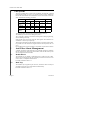
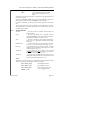
The System
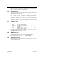
The Care-Tech 2000 Series consists of an 'End Station' with blank lid, controlled
from Remote Keypads (up to five) or optional remote keyswitch. Differences
between the three members of the 2000 Series concern the number of detection
zones, and detection technology, as follows:
2300
Technology
2700
2500
D. Pole
EoL
D. Pole
EoL
iD
No. of zones
(basic)
4
8
8
16
30
1 expander
8
16
12
24
-
2 expanders
-
-
16
32
-
-
Up to 4
Up to 4
Multiple End
Stations
No
The keypad includes 10 numeric digits used for entering codes, etc.
The ABCD keys are used in 'Area setting' the system.
The * (NO) and # (YES) keys are used in selecting choices whilst programming,
and in confirming code entry.
Some keypads may not show the 'NO' and 'YES' legends. These functions are
available on '*'' and '#' keys respectively.
The keyswitch (if fitted) provides alternative means to set and unset the control.
It is possible to set the control from keypad and unset with keyswitch, and vice
versa.
Down loading of the system is possible, in conjunction with 'In-Site PC software.
3
Anti False Alarm Management
A number of features of the 2000 Series are specifically designed to minimise
the risk of false alarms. When using these features, take care that security levels
are not compromised. These include
3.1
Double Knock
This attribute may be applied to individual zones to reduce the risk of false
alarms. The zone trigger will only be accepted by the control if it lasts in excess
of 10 seconds, or is repeated within that time.
For further information refer 9.1.3
3.2
Dual Trip
This attribute may be applied to pairs of zones, such that an alarm will only be
generated if both zones are in fault condition simultaneously.
For further information refer 9.1.3
Page 6
Issue 3a
2000 Series Diagnostic Alarm System Programming Manual
3.3
Misoperation (Abort) Signalling
A dedicated 'abort' output is available, and may be programmed to ANY of the
digi-comm channels. This output will fire whenever a valid user code is entered
following the generation of an 'Intruder' output signal to the Alarm Receiving
Centre. The output will reset at the next code entry.
Abort may also be signalled by the 'restore' of the 'Intruder' signal, which will
take place whenever a valid user code is entered following the generation of an
'Intruder' output signal to the Alarm Receiving Centre. This method is also
available using 'Area Alarm' signals for 'split' systems.
See also 'Entry Pre-Alarm Timer' and 'Engineer Reset Time' below.
3.4
Sequential Confirmation Signalling
A Sequential Confirmation Output is available, and can be programmed to ANY
digi-comm channel. This output functions as follows:
a. The output is inhibited for 180 seconds after the system is set, and after
the generation of an alarm on entry
b. The output will trigger when a further zone* goes into fault condition
following the end of the inhibit period.
c. The output will trigger at the second zone* trigger following a rearm.
d. The output will reset at next code entry.
* - applicable to 'Intruder,' '24 Hour Tamper,' and 'Walk Through' Zone
types only, except that a 'Walk Through' zone will NOT trigger a
confirmation signal if an 'Entry Exit' zone has been triggered.
It is essential that the system installation complies with the requirements of
DD243 (NACP14) if this facility is to be used. The 2000 Series cannot be
programmed to signal 'confirmation' from individually selected zones only.
3.5
Entry Pre-Alarm Timer
This facility permits the programming of a delay before the 'intruder' signal is
triggered in the event of an alarm being generated by entry time-out, or deviation
from entry.
3.6
Delay Bell
Any programmed bell delay will NOT be valid for the first 180 seconds after the
system is set. Nor will it be valid in the event of an alarm triggered by entry
time-out, or deviation from entry.
This ensures that the user will be aware of any alarm triggered in time to be able
to unset, and thus generate the 'abort' signal to avoid police attendance.
3.7
Engineer Reset Time
This enables a delay to be programmed to avoid the need for Engineer Reset
when an alarm has been 'aborted' without being policed.
For further information refer 9.8.2
This facility is not required to comply with DD243 (NACP14), and should
NOT be used such that engineer reset is not valid in the event of police attending
site.
January 2000
Page 7
Castle Care-Tech Ltd.
4
End Station and Keypad Addressing
Before powering up and programming, a check should be made to ensure that all
coding selections are correctly made:
4.1
End Stations
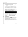
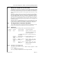
4.1.1
Address Switches (2500 and 2700 systems)
Address
4.1.2
Switch A1 Switch A2
SINGLE ES system
Closed
Closed
A
Closed
Closed
B
Open
Closed
C
Closed
Open
D
Open
Open
these
addresses
must
NOT
be
duplicated
Mode Switch (2300 and 2700 Systems)
This selection must be made BEFORE powering up.
For use with Double Pole mode, the 'EoL' switch should be CLOSED
For use with End of Line mode, the 'EoL' switch should be OPEN.
In the event of this switch setting being changed after power up, it will be
necessary to power the system down and up again, 'clean start' the NVM and
reprogram.
4.2
Slave Keypads
SLAVE keypads enable additional control points to be added to the system.
These provide the same facilities as the Master keypad.
Slave Keypads must be correctly coded BEFORE the system is powered up,
setting the 'dip' switches as per the following table:
Address
Switch A
Switch B
0
Closed
Closed
1
Closed
Open
2
Open
Closed
3
Open
Open
4
4.3
These addresses must NOT be
duplicated.
For use with 'Gateway' systems only, special '5th Slave'
software (CT.2110) may be used in a master or slave keypad.
Engineer Keypad
Provision is made for a keypad to be plugged onto the End Station to provide a
temporary control point whilst programming, testing, etc. This must be a
SLAVE keypad, coded to address 3 (provided that address 3 is not already in
use). This may be connected and disconnected as required whilst working
on the system, without the need to power down or re-start.
Page 8
Issue 3a
2000 Series Diagnostic Alarm System Programming Manual
5
Printing from the System
The printer, of standard IBM PC-compatible 'Centronics' parallel type (eg Epson
P40, Seiko DPU40, Datec DP1014.0400K, etc.), should be connected to the
'PRINTER' port at the left hand edge of the End Station pcb, using the correct
cable (CT5400 or CT5500). The loom should be connected with the BROWN
wire to pin 1 of the pcb connector - ie the bottom of the pcb.
The loom should NOT be left in place when the printer is 'OFF LINE' or
disconnected.
Due to the wide variety of software driving requirements, it is NOT possible for
the 2000 Series to correctly drive all types of printer, or for Castle Care-Tech to
advice on correct printer 'Dip-switch' settings.
5.1
Printing from Multiple End Station systems
As each ES is supplied with a parallel printer port, the multi- ES system can
intelligently locate the printer if it is connected to any ES. Log printouts can be
made from any ES and the keypad display will show you, before printing, where
it has found the printer connected.
Diagnostic printouts must be made from each ES individually, for the
information relevant to that ES. This means that all of the diagnostic features of
the 2000 System are available on the entire system.
6
Use with Communicators and STUs
6.1
Digital Communicator or RedCare 'STU'
The system is compatible with any 'industry-standard' plug-on communicator, or
may be used with 'stand-alone' devices via an interface.
All signalling outputs are fully programmable
Ensure that the communicator PROM is programmed correctly for the
signalling polarity as well as required channels.
A STU PROM must be programmed as CODE 3 for ALL channels. If a
'stand-alone' EURO-STU is used via a carrier pcb, the STU PROM must be
programmed as CODE 1 for all channels EXCEPT channel 4 which must be
programmed as CODE 3
For use with Digi-Com 'Tell-Back' / Red Care 'Reset' facility, refer 9.8.4
Responses toTelecom line faults harmonise with NACOSS directive NAD1, see
'Operating Instructions' for full details.
6.2
Multiple End Station Systems
The plug-on communicator outputs are live on
END STATION 'A' ONLY.
January 2000
Page 9
Castle Care-Tech Ltd.
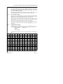
6.3
Communicator Pin / Channel Assignments
Discounting the two reserved pins at the top of the left hand connector, the
pins are numbered top to bottom, 1 to 8 on left hand connector, and 9 to 16 on
right hand connector. The outputs are completely programmable (see 9.7.3), the
factory default assignments are as follows:
Output No.
(see 15.7)
PIN
No.
1
2
3
4
5
1
2
3
4
5
6
7
8
7
6
8
9
10
11
12
13
14
15
16
Default Assignment
Channel
Digi STU
Aux/Fire
1
1
PA
2
2
Intruder
3
3
Open/Close
4
4
Trouble
5 5 or 7
Tell Back I/P
Comm Fail I/P
Low Volts
Lo
Lo
Bat Bat+12v
0v
Not Used
+5v
Abort (Mis-Operation)
6
Confirmation
7
6
Line Fail I/P
Digicom Reset
8
8
All output channels are 0v changing to +5v in alarm condition.
All inputs trigger with the application of +5v signal.
In the event of the End Station losing communication with the Master
Keypad (or Gateway) whilst set, channels 3 and 5 will self activate.
Low volts is automatically reported.
For further information concerning Abort (Misoperation) signalling, and
Sequential Confirmation, refer 3.3 and 3.4
Page 10
Issue 3a
2000 Series Diagnostic Alarm System Programming Manual
7
7.1
Power Up
Initial Power Up
Power should be applied from the Mains first. The system must have a standby
battery connected during use (7 AHr is recommended).
Slave keypads MUST be connected to the system before powering up, or they
will not be recognised by the system.
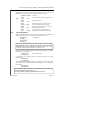
On powering up, the Master Keypad will progressively display:
CASTLE CARE-TECH Ltd.
2500 System v 4.1
(as appropriate)
iD mode
(as appropriate)
System Ready
Slave Keypads will display:
CASTLE CARE-TECH Ltd.
2000 Slave v2.7
Awaiting COMS
Slave Addr.x
'x' reflects the address coding (see 4.2)
System Ready
A 'System Tamper' or 'RS-485' alarm initiated at power up may be cancelled
with any valid code (including engineer code)
7.1.1
Clean Start
It is essential that a 'CLEAN START' is performed at initial power up to ensure
that the NV memory is initialised correctly. If the NVM chip is ever removed, it
MUST be replaced in the Master Keypad (or Gateway) BEFORE commencing
programming. To ensure you have a CLEAN START, follow this procedure:
With the display showing "CLEAN START?" in the Engineering menu, key in
"YES" followed by the number 2000, and the factory-set programme defaults
will load in the system memory. When completed, the display will show
"Initialised" and move to the next programming item.
Remember, the OLD programme is still stored in the NV Memory chip until you
leave the Engineer menu. At the point of exiting that menu, the message
"Updating NV Memory" will appear, confirming that the new program
parameters are resident in the NV Memory chip. Therefore, NEVER power
down whilst in Engineering mode.
If it is necessary to perform a 'Clean Start' with the NVM removed, after
powering up, enter engineering mode and select 'CLEAN START.' Insert the
NVM at this point, then enter code 2000, and proceed as above.
If a replacement NVM is being fitted, it is essential that the LOGS are
CLEARED before leaving Engineer mode.
January 2000
Page 11
Castle Care-Tech Ltd.
7.1.2
Subsequent Start
Powering up a 2000 series system fitted with a programmed NVM will
automatically load the system parameters from the NVM.
When adding slave keypads to the system, power should be removed first, or
they will not be recognised by the system. "Restarting" the Master keypad (or
Gateway) (by briefly shorting the 'R' and 'S' pins) will also cause it to search for
additional slaves, or correct for any removed.
7.2
Fault Finding
Power - Up Problems
1.
Power down and check the component parts of the system:
a. Master Keypad - identified by the NV Memory chip.
b. End Station - correctly coded.
c. Slave Keypads - coded to different addresses.
2.
Check Wiring between a, b and c above is correct.
3.
Power up on mains and check that there is 13v or more at the End Station
COMMS power supply terminals for the keypads.
4.
Supply voltage at keypads, at power up must be at least 12v.
5.
If keypad displays are blank - check their supply voltage.
6.
If keypad keys do not respond, check coding is correct, and keypad tamper
switch is closed correctly.
RS-485 Failure
If this message is displayed on the Master Keypad, there is a fault on the
communication link between the various keypads and the End Station.
Page 12
a.
Check voltage at keypads
b.
If Slave Keypads are present do they display 'RS-485 Failure' as well? If
YES then the fault is almost certainly at the End Station.
c.
If Slave keypads display 'Awaiting Comms', then the fault may lie with a
Slave keypad. Disconnect all slaves and see if the system responds
correctly with just the Master keypad. Replace slaves one at a time,
reinitialising the system each time, until the fault is discovered.
d.
If the End Station loudspeaker emits a 'beep - pause - beep' tone, with only
the Master Keypad connected, then the fault will lie with the wiring, or the
Master Keypad.
e.
Sometimes problems induced by an engineer shorting wires etc can be
overcome by shorting the RESTART pins on the End Station and on the
Master Keypad (or Gateway). This will totally reset the system and
re-load the system parameters from the NV Memory.
f.
If using multi-core cable between Keypads and End Station, whilst it is
advisable to common up multiple cores for the SUPPLY (+ and -)
connections, the COMMUNICATIONS LINK should have only one core
connected to each connection (T and R). Doubling up on these connections
is not necessary, and can cause 'ringing' resulting in data corruption.
DOUBLE UP SUPPLY CONNECTIONS ONLY.
Issue 3a
2000 Series Diagnostic Alarm System Programming Manual
8
Engineering Menu
Programming of the system parameters may be carried out from any keypad.
The ENGINEER CODE permits access to the Engineer Menu to use the
programming and diagnostic features of the system. The code may also be used
from the 'System Ready' prompt to set and unset the system whilst testing and
commissioning, to avoid the engineer having to know a Manager or User code.
The Engineer code will NOT unset the system if it has been set using a Manager
or User code, nor is it possible to perform sequences of area set and unset
operations.
The default code is 1111, this may be changed as described at 9.10
A loose programming chart is provided to assist in establishing the required
system parameters, before programming the system.
Ensure that the system is NOT in Engineering mode before powering
down, or newly programmed information will not be saved, and, in some
circumstances, memory corruption may occur.
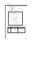
8.1
Engineering Menu Options
The ENGINEERS menu is entered through the MANAGER menu. :
Manager Menu ?
( 1234)
Engineer Menu ?
( YES key)
Enter Code :
( 1 1 1 1 is default code )
CLEAN START ?
( first option )
Alternatively, the Engineer Code may be entered directly at the 'Manager
Menu? display
The full range of Engineering Options that appear on the display is detailed
below, these are accessed by scrolling forwards with the * key, or backwards
with the 'B' key.
CHANGE ZONES ?
CHANGE TIMERS ?
SET TIME AND DATE ?
CHANGE EXIT MODES ?
SOUNDER OPTIONS
ALARM RESPONSE MENU
ASSIGN OUTPUTS
SITE OPTIONS
REDEFINE SIGN-ON MESSAGE
CHANGE CODES
ENGINEER TESTS
ENGINEER DIAGNOSTICS
LOG REVIEW
PRINT LOGS
CLEAR LOGS
PRINT SYSTEM PARAMETERS
EXIT ENGINEER MODE
Other options are available on systems fitted with Gateway Module.
To cycle through the Engineer menu again, press 'NO' five times.
January 2000
Page 13
Castle Care-Tech Ltd.
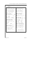
Some engineering options have further choices, for example :
CHANGE ZONES ?
Zone Type
Assign Areas ?
Assign Attributes?
Assign Name to Zone ?
(Quick exit from option: enter zone no.[99] # )
CHANGE TIMERS ?
Exit Route
Entry Route
Bell Duration
Bell Delay
Re-Arm Number
Deterrent Time
Entry Pre-Alarm
SET DATE & TIME
CHANGE EXIT MODES
Area Set ABCD
SOUNDER OPTIONS
Strobe Confirms Exit
Sounder Continue after Bells
Chime Option
Deterrent
Volume Settings
ALARM RESPONSE MENU
ABCD
ASSIGN OUTPUTS
Change Standard O/P 1 to 4
Change Digicom Outputs
Change Output Module
SITE OPTIONS
Engineer Reset
Engr. Reset Time
Dual Trip Fires Confirm
Digi-Reply
Enter Site Code
Silent Set Menu
Omit Zones Menu
Select Areas Menu
Common Lobby
REDEFINE SIGN-ON MESSAGE
CHANGE CODES
Change Engineer Code
Change Operator Codes
(Quick exit from option : enter code no [99] #)
Page 14
Issue 3a
2000 Series Diagnostic Alarm System Programming Manual
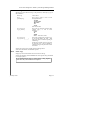
ENGINEER TESTS
Bell. Strobe. Sounder.
Outputs 1 - 4.
Test Digi-com
Test Inputs
Walk Test. Print Walk Test.
Inputs Test.
ENGINEER DIAGNOSTICS
Display iD Point Condition ?
Line Diagnostics
Display Current and Voltage?
Display End Station Faults ?
Print Diagnostics ?
Print Circuit Conditions ?
(These diagnostic print routines cannot be aborted and include
several delays while current tests are performed.)
LOG REVIEW
Alarm.
Activations.
Trouble.
(Scroll events forward with 'A' key, backward with 'C'' key)
PRINT LOGS
Alarm.
Activations.
Trouble
(To abort printing : Hold NO key down until 'Beep' is heard).
CLEAR LOGS ?
PRINT SYSTEM PARAMETERS ?
EXIT ENGINEER MODE
(Press 'NO' key 5 times to go around menu again)
8.2
Clean Start
It is essential that a 'CLEAN START' is performed at initial power up to ensure
that the NV memory is initialised correctly. If the NVM chip is ever removed, it
MUST be replaced in the Master Keypad (or Gateway) THE CORRECT
WAY ROUND BEFORE commencing programming. To ensure you have a
CLEAN START, follow this procedure:
With the display showing "CLEAN START?" in the Engineering menu, key in
"YES" followed by the number 2000, and the factory-set programme defaults
will load in the system memory. The display will then show "Initialised" and
move to the next programming item.
Remember, the OLD programme is still stored in the NVM chip until you leave
the Engineer menu. On leaving that menu, the message "Updating NV
Memory" will appear, confirming that the new program parameters are loaded
in the NVM chip.
Following a 'Clean Start' do NOT exit with 'A' or 'C' keys, scroll to 'Exit
Engineer Menu' and press 'YES.'
January 2000
Page 15
Castle Care-Tech Ltd.
9
Programming the System
9.1
Change Zones
To select the zone to be programmed:
Select Zone
No:
[01]
Use 'YES' key to select Zone 1, or 'NO' key
to scroll to number required. Alternatively,
enter required zone number from numeric
keypad, and select with 'YES'
This option allows the customising of the messages that are displayed as well as
tailoring the performance of the actual alarm system itself, eg
Change Zones ?
(YES key )
Select Zone
Number [ 01 ]
(NO to increment the number, or press the
digits of the zone number - eg 1 and 3 for
zone 13) and YES.
NB : selecting a number higher than the
highest zone available will exit this menu.
Zone [ 13 ] Type :- (NO scrolls round the available zone types.
Isolated
Press YES when correct type is displayed to
continue - or, using the numeric keypad,
simply press the digit that corresponds to
the zone type shown at 9.1.1 eg - 4 =
Intruder)
Zone [13] Type :Silent P.A.
(Press YES key when the correct type is
displayed)
Assign to Area ?
(YES / NO, see 9.1.2)
Assign Attributes ?
(YES / NO, see 9.1.3)
Assign a Name ?
(YES, see 9.1.4)
To exit from this item, select a number higher than the highest possible zone
number on the system (eg. 99 for a standard 2500 system) and press YES
A printout of all zone programming information is available as part of the
'System Parameters' printout (see 10.6)
9.1.1
Page 16
Zone Types
0. Fire
= When activated triggers communicator output.
(Aux/Fire Signal), and provides a (pulsing) warning
tone on speaker and bell outputs. After Bell time, the
internal sounder will continue until a code is entered.
NOTE: The 2000 series are NOT designed to meet Fire
Alarm standards, but regulations relevant to the selection
and siting of fire detectors MUST be followed.
1. PA
= Personal Attack. Usually push button devices.
Produces a full alarm at any time when pressed,
generating a PA communicator output (PA Signal).
2. Silent PA
= Personal Attack alarm, generating a communicator
(PA Signal) output without audible alarm.
Issue 3a
2000 Series Diagnostic Alarm System Programming Manual
3. 24Hr Tamper
= A security wiring feature, gives a local alarm, and
communicator (Trouble Signal) output, if wiring is
broken or shorted, whilst the system is unset, in addition
to the normal intruder response if set.
4. Intruder
= This is the usual designation for an alarm system zone.
Activating an alarm output and communicator (Intruder
Signal) output when the system is armed.
5. Final exit/entry
= The last detector on the entry/exit route. Typically the
front door.
6. WT-E/E in Area
= A 'Walk Through' zone (as type A below).
If the system is partially set only, this zone behaves as
final exit/ entry zones.
7. Deterrent
= 24Hr monitoring that will trip a unique output (outputs
1 to 4) that may be used to deter intruders at the site
perimeter, but not trip any form of system alarm
condition. See 'Assigning Outputs'at 9.7
8. Auxiliary
= An independent zone tripping a unique output for
things such as water, gas detectors etc. See 'Assigning
Outputs.' Also triggers communicator output (Aux/Fire
Signal) and system sounder. Auxiliary zone trips will be
logged whether the system is set or not.
9. Isolated
= Circuit/Zone Non-Active
A. Walk Through
= A detector on the exit/entry route that is before the final
exit/entry door, typically a PIR mounted in the hallway.
This may be 'walked through' during entry providing the
final exit/entry door is opened first.
These zones function as 'Walk Though' in all set modes.
B. E/E-WT in area
= A detector on the exit/entry route that will start entry
time when triggered, if the system is fully set.
This zone will function as a 'Walk through' zone in area
set modes.
C. Shunt
= A switch, which, when closed, will shunt out of
operation a zone, or group of zones, allocated to the
associated 'shunt list'. See 9.1.1.1
D. Push to Set
= 2500 ONLY; Provision for mounting a push button
outside the building to complete exit procedure, as an
alternative to the use of Input 1. (see 9.1.1.2).
The zone type may be selected either by scrolling to the type required with the
NO key, and selecting with YES, or by entering the type number (or letter) from
the keypad, followed by YES.
NOTE:
January 2000
If a 'Walk through' zone is triggered whilst the system is
set, an alarm will NOT be generated instantly. The system
will store this trigger for 5 seconds. If a 'Final Exit/Entry'
zone is triggered during this time, ENTRY TIME will
start, otherwise an alarm will be generated.
Page 17
Castle Care-Tech Ltd.
9.1.1.1
Programming Shunt Zones
On defining a 'Shunt' zone, as above, the display will show
'Shunt List xx
-- -- -- -- '
^
= cursor pointing to first dash
Enter the first zone number (2 digits) which it is required to add to the list,
followed by YES. This will appear beside the dash, thus
'Shunt List 15
-- 21 -- -- '
^
Continue to add zone numbers as required (any number may be entered).
To delete a zone from the shunt list, move the cursor to the zone number (using
'B' key to move left, and 'D' key to move right), and press the 'NO' key.
Press 'YES' to complete programming and move to next option.
Zones may NOT be assigned to more than one shunt list.
Isolated zones cannot be entered on a shunt list.
Any zone present on a shunt list which is subsequently isolated
will automatically be deleted from the shunt list.
A shunt list may be cleared completely by reassigning the zone as an alternative
zone type, and then reprogramming the zone as a shunt zone again.
In use, whenever a shunt zone is CLOSED, (eg by closing a keyswitch wired to
the zone input, the zones assigned to it will be shunted (ie inactive). When the
shunt zone is opened, the relevant zones will be live after a 10 second check
period. If, during that period, a fault exists on a shunted zone, the shunt will
remain in force to prevent an alarm from being generated.
'Zones Shunted,' 'Shunt Fault' and 'Zone Unshunting' outputs are available for
use in conjunction with shunt zones (see 9.7)
9.1.1.2
Push to Set Zones (2500 ONLY)
A zone programmed as 'Push to Set' will accept a standard normally open push
button, and will function in the same way as a push button wired into Input 1. A
'door bell' facility will also be available via this zone
Selecting this zone type does not permit the programming of any attributes or
area assignments.
Page 18
Issue 3a
2000 Series Diagnostic Alarm System Programming Manual
9.1.2
Area Assigned
ABCD
= Zones assigned to ABC or D will be
active whenever that specific area is
armed.
To adjust the areas for which the zone is assigned, press the appropriate key(s)
for the zones required.
To select as 'COMMON LOBBY' area, press any of the ABCD keys twice. The
display will show areas selected as 'COMM' for 'Common Lobby.'
For further information concerning Common Lobby operation, refer section
9.8.9
Note: The Deterrent circuit option is valuable to warn of approach to a 'set' area.
The deterrent tone and a visual warning sign such as 'Alarm Active' (driven by
an output) may be utilised.
9.1.3
Zone Attributes
Non Omit
= The zone cannot be manually omitted during the
setting procedure.
Chime
= The zone will CHIME if it is activated while the
system is DISARMED. The volume and rate of chime is
adjustable under software control. See 9.1.3.1
Soak
= The zone will indicate a fault without generating an
alarm, see 9.1.3.2. Applicable to 'Intruder' and 'Tamper'
zones only.
Double Knock
= Any alarm activation will be signalled if it lasts for
over 10 secs, or if two activations occur within 10 secs.
Dual Trip
= Two adjacent zones (eg. 5 and 6) are paired. An alarm
condition will be generated if both zones are in alarm
condition together, see 9.1.3.3
Special Log
= Every opening and every closing of a zone with this
attribute will be entered in the 'Trouble Log' whether or
not an alarm was initiated, see 9.1.3.4
Anti-Mask
= The zone will be checked before the system sets, and
interrupt the setting procedure if it has not been activated
since the system was last unset, see 9.1.3.5
NOTE :
These choices ( [YES] or [NO] ) are scrolled through by accepting them with the
YES key. The NO key will change the choice. For example :
NON - OMIT [YES]
(NO changes the choice)
NON - OMIT [ NO ]
(NO changes the choice)
NON - OMIT [ YES ]
(YES accepts the choice and
moves to the next option)
etc ....
CHIME
January 2000
[ NO ]
Page 19
Castle Care-Tech Ltd.
9.1.3.1
The 'Chime' attribute
If zones have been configured to 'CHIME' whilst the system is unset (eg shop
front door, garage or shed door), the following message will show, along with
the Chime tone, indicating that a door has been opened:
ATTENTION!
ZONE 1
The tone may be silenced using the 'YES'
key.
See separate option (9.5) to select chime as 'single' or 'follow'
All indications will clear by scrolling around the TOP MENU with the 'NO' key.
Any indications remaining show that the particular fault remains current.
Please note that the CHIME attribute is designed to be used only with the
following zone types:
INTRUDER, ENTRY-EXIT, WALK-THROUGH, DETERRENT
Whilst the system will accept an attempt to select this attribute for other types of
zone (PA, SILENT PA, FIRE, 24-HOUR, AUXILIARY), this will result in the
system refusing to accept the entry of an operator code to cancel an alarm
triggered by such a zone until the fault has been cleared / reset.
The chime facility may be disabled / enabled by toggling the 'C' key whilst the
'System Ready' prompt is displayed, at any keypad, as follows
Single press Small 'c'
System chimes only
Second press Capital 'C' System chimes and Displays zone triggered.
Third press
Chime off
9.1.3.2
The 'Soak' Attribute
A zone programmed with this attribute will NOT trigger an alarm condition, but
function as follows:
In fault when setting A fault will indicate, preventing the system from
setting.
Activated whilst
No alarm will be generated.
system set
At unset, the display will show 'Soak Failed.'
Activation will be recorded in 'Trouble log'
9.1.3.3
The 'Dual Trip' attribute
This option must be selected for two adjacent zones (eg zones 5 and 6). The
software searches either side of each zone and signals an alarm if two adjacent
zones are open together. If more than one pair is being used, a "gap" should be
left between pairs, or, for example if 5, 6, 7 and 8 were programmed as if two
pairs, 6 and 7 would also act as a pair.
During setting procedures any ONE zone in alarm will indicate a fault in the
usual way. When set, if only one zone of a pair is triggered, it will NOT trigger
an alarm, but will display as ' Dual Trip [ ] ' when unsetting, and record
similarly in the Trouble log.
An option is available to permit a 'dual trip' pairing to directly trigger the
'Confirmation' signal to the communicator in addition to 'Intruder.' (see 9.8.3)
Page 20
Issue 3a
2000 Series Diagnostic Alarm System Programming Manual
9.1.3.4
The 'Special Logged' attribute
Every opening and every closing of a zone with this attribute will be recorded in
the 'Trouble Log' whether or not an alarm was initiated. The entry in the Trouble
Log shows 'MONITOR ON/OFF' and identifies zone number. See 9.7 for
corresponding output configuration.
Dual-Trip or Double-Knock zones assigned the 'Special Logged' attribute will
log WHENEVER a zone is activated, not just if an alarm is generated.
9.1.3.5
The 'Anti-Mask' attribute
The zone will be checked before the system sets, and interrupt the setting
procedure if it has not been activated since the system was last unset. The
display will then show 'Not tested' and identify the zone(s) affected.
Activating these zones will cause them to disappear from the display, and the
setting procedure will continue when the 'YES' key is pressed. Pressing the 'NO'
key will return the system to 'day' mode for checks to be completed..
Alternatively, pressing 'YES' will abort the check and permit the system to set.
In this event, any untested zones will be recorded as 'Masked Zone [ ]' in the
Trouble log.
9.1.4
Assign Name to Zone
It is possible to assign a name to each zone on the system to make it more
'customer friendly'. This allows you to type in your own text for each zone.
Assign a Name
(Press YES)
to zone
Zone [13] Text:
>
Text characters are entered one at a time, using 2-digit codes from the following
table.
A
33
N
46
a
65
n
78
0
16
Space
00
B
34
O
47
b
66
o
79
1
17
C
35
P
48
c
67
p
80
2
18
D
36
Q
49
d
68
q
81
3
19
,
.
12
E
37
R
50
e
69
r
82
4
20
/
15
F
38
S
51
f
70
s
83
5
21
"
02
13
14
G
39
T
52
g
71
t
84
6
22
&
06
H
40
U
53
h
72
u
85
7
23
(
08
I
41
V
54
i
73
v
86
8
24
)
09
J
42
W
55
j
74
w
87
9
25
*
10
K
43
X
56
k
75
x
88
+
11
L
44
Y
57
l
76
y
89
!
01
M
45
Z
58
m
77
z
90
#
03
January 2000
Page 21
Castle Care-Tech Ltd.
After entering each code, the cursor will move to the next position. The 'D' key
may be used to move the cursor position to the right, and the 'B' key to move it
to the left.
Alternatively, text may be entered by using the 'A' and 'C' keys to scroll through
the available characters, and the 'B' and 'D' keys to move left and right.
Press the 'YES' key to terminate the text string.
9.2
Page 22
Change Timers
Exit
= Time allowed to exit the building (with all zones
clear) before the system sets. If a detector is open the
timer is held up until it is closed.
Entry
= Time allowed to enter the building, via the correct
route, and switch off the system.
Bell
= Time elapsing before the bell will stop ringing during
an alarm condition.
Bell Delay
= Time elapsing after an activation before the bell will
start to ring (to allow police to arrive and apprehend an
intruder).
This programmed delay does NOT become operative
until 180 seconds after the setting procedure is
completed.
NOT to be used unless a communicator is fitted.
Re-arm
= The number of times the system will re-arm itself at the
end of bell time. If the alarm was not confirmed, a
qualifying repeat alarm will initiate a 'confirmation'
signal.
A repeat 'intruder' signal will NOT be generated after a
re-arm.
Triggering of an 'Entry-Exit' zone will start normal entry
time.
Deterrent
= The number of seconds the deterrent output (output 1
to 4) is active when the deterrent zone is in alarm.
Entry Pre-Alarm
= A delay applied to the communicator output in the
event of an alarm caused by deviation from entry route;
during which the system audible warning devices only
will function, thus providing the user with the
opportunity to cancel the accidental alarm.
(Not required by ACPO / NACP14)
Issue 3a
2000 Series Diagnostic Alarm System Programming Manual
9.3
Set Date and Time
Setting the Real Time Clock time and Date ensures that all events will be
stamped with the correct date and time. Select the option as follows:
Set Date and Time ? ( YES key )
Year :
9.3.1
Enter
[ 90 ]
1996)
( press the digits for the year, eg 9 and 6 for
Enter
Year :
[ 96 ]
Enter
Month:
[Jan]
(Scroll with the NO key until the correct
month is displayed, then press YES)
Enter
Date :
[ 01]
(Press the digits of the date, eg 2 and 4 for
the 24th, then press YES)
Enter
Time :
[ 0938]
(Enter the time by pressing the digits,
expressed in 24 hour format, then YES)
(YES when correct)
Clock Adjustment
After entering the date and time, an option permits the clock to be adjusted by a
number of seconds per day to compensate for component tolerances
NO toggles to
Clock [Loses]
Secs/day [_ _ _ ]
Clock [Gains]
Secs/day [_ _ _ ]
If the system is fitted with END STATION software issue 6.0 or later,
this should NOT be used . The clock will be synchronised with mains
frequency, and needs no adjustment. In Multi-ES systems, the 'A' ES
must be fitted with 6.0 software for this to function correctly.
If used with earlier End Station software, establish what adjustment is required,
and enter this, as, for example
Clock [Loses]
Secs/day [ 054 ]
Press YES to confirm
If this function has previously been set, the display will show the existing
information, eg
Clock [Gains]
Secs/day [143]
This setting should be adjusted if required - eg if the above system is now losing
33 seconds per day, the setting should NOT be changed to a 'Loses' setting, but
be adjusted to
Clock [Gains]
Secs/day [110]
The clock adjust facility should ONLY be used when the system End Station
is fitted with software issues prior to 6.0.
It is NOT possible to upgrade such End Stations to Issue 6.0.
January 2000
Page 23
Castle Care-Tech Ltd.
9.4
Change Exit Modes
Lock Set
= The system will only set when the lock on the final
door is secured. Lock contact should be wired to a
biscuit programmed as 'Final Entry Exit.' Reopening
the lock will start entry time.
Push - Set
= The system will only set if the push button at
the final door is pressed (normally sited outside)
Timed
= The time allowed for exit before the system sets.
Quick Set
= System set occurs within 5 secs (for use where Areas
ABCD are used independently within one building).
Press the NO key to change the selection. The YES key accepts the choice
and moves you on to the next option.
AREA SETTING
If different areas are programmed to different exit modes, the system will
require the HIGHEST priority to be used when multiple areas are set, in
the order shown above.
9.5
Sounder Options
Strobe Confirm Exit
= At final set the strobe output will be live
for 5 secs to confirm 'system set'.
Sounder Continue
after Bells
= After Bell cut-off time expires, the
internal speaker(s) will continue to sound.
Chime Option
Follow
Single
=The tone follows the opening of the door
(Door Open = bip bip bip bip. . . . Closed =
silent).
= The tone sounds once when the door is
opened
Deterrent
Follow
Timed
Volume Settings
Page 24
= The programmed output follows the
opening of the door (see 9.1.1) (Door Open
= live. Closed = off).
= The output latches once the door is
opened and resets when the timer expires
(see 9.2)
= Each different sound signal may be
programmed to 'Low,' 'Medium' or 'High'
volume levels.
Issue 3a
2000 Series Diagnostic Alarm System Programming Manual
9.6
Alarm Response
This option allows the engineer to specify the type of alarm response that is
required in each area when an activation occurs. The choices for each of the
areas A,B,C and D are :
Keypad Bleepers
Internal Sound
Local Alarm
Full Alarm
( Bell, Strobe and Sounders )
( Communicator and Local Alarm )
NOTES :
Press the NO key to change the selection. The YES key accepts the choice and
moves on to the next option.
If the FULL ALARM response has been selected for any area, any BELL
DELAY programmed into the system will be applied to an alarm created within
that area, even if the system is area set only.
For details of 'Abort' and 'Confirmation' signalling, refer Section 3
9.6.1
System Tamper Response
If the system is AREA SET, a system tamper (ie Keypad or SAB tamper, or
Code Guessing alarm) will generate an alarm corresponding to the highest level
for any area set at the time of the alarm.
9.7
Assigning Outputs
The 2000 Series has the following outputs available, each of which can be
programmed to signal any one of the configurations outlined at 9.7.1
Digi-comm pins - 8 outputs
End Station Outputs 1 - 4 (2300 has 1 and 2 only)
In addition, further outputs are available at modules wired to the system as
follows:
Network Output Modules
- up to 8, with 8 outputs each - see 9.7.4
(Multiple End Station systems can accept up
to 16 modules)
These outputs switch as follows:
January 2000
Digi-comm outputs
= 0v, switching to +5v when active
LOGIC LEVELS ONLY available - no
current may be drawn.
End Station output 1
= +12v, switching to 0v when active.
A maximum of 65mA may be drawn at either
polarity
End Station O/P 2 - 4
= +12v, switching to 0v when active.
A maximum of 65mA may be drawn WHEN
ACTIVE ONLY.
Page 25
Castle Care-Tech Ltd.
Network O/P Modules
9.7.1
Outputs 1 and 2
= +12v, switching to 0v when active.
A maximum of 500 mA may be drawn
WHEN ACTIVE ONLY
When used as sounder outputs, volume level
is adjustable on module.
Outputs 3 and 4
= +12v, switching to 0v when active.
A maximum of 65mA may be drawn WHEN
ACTIVE ONLY
Outputs 5 to 8
= Changeover voltage free relay contacts.
Contacts rated at 1 amp 24v DC/120v AC.
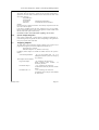
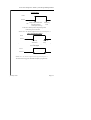
Output Types
PIR Latch 1
Inactive
Day
Active
Set*
*- Also changes in Walk Test
Alarm or
Unset
AUX
Inactive
Active
Aux Zone
tripped
Code
Entered
NOTE: Opening an Auxiliary Zone will also trigger an output programmed as
'Fire/Aux Signal'
Viper 12v Reset
12v
0v
<
2 secs
>
System switch -on
This configuration is shown as if programmed to End Station OUTPUT 1. If
programmed to any other output (other than Network Output Module relay
outputs) an external relay must be used to switch the current required at 12v.
This is designed to provide the 'power off' reset required by early VIPER, and
certain other detectors. It re-triggers every time any part of the system is set,
hence under area setting conditions, the reset signal can cause false alarms. The
preferred reset for VIPER + and VIPER 3 detectors (Viper 'Display Reset' or
'Set/Unset' terminal) should be used when area setting:
Page 26
Issue 3a
2000 Series Diagnostic Alarm System Programming Manual
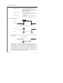
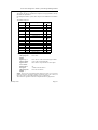
Viper Set/Unset
Inactive
Active
On
Additional
Off
area set
24 Hour Tamper
Inactive
<Duration of fault
>
Active
Tamper fault occurs
Tamper fault clears
This output is live when a zone programmed as '24 Hour' is triggered - NOT for
system tamper faults, etc.
Switch-On Indication
Inactive
Active
System
Switched on
System
Switched off
Deterrent
Inactive
Active
Deterrent Zone
triggered
January 2000
Follows
option
selected
Page 27
Castle Care-Tech Ltd.
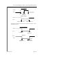
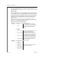
Area Set: Area A, B, C or D
Inactive
Active
Area is Set
Area Unset
NOTE: The Area Set output will be generated whenever that area is set,
including when other areas are already set.
Area Alarm: Area A, B, C or D
Inactive
Active
Alarm in Area
Code entered
NOTE: The Area Alarm output will be generated whenever an alarm is
generated within that area, whether other areas are set or not.
Special Logged
Inactive
Active
Special Logged
Zone opened
Zone
Closed
PIR Latch 2
Inactive
Day
Active
Set *
* - Also active in Walk Test
Page 28
Alarm or
Unset
Issue 3a
2000 Series Diagnostic Alarm System Programming Manual
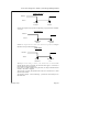
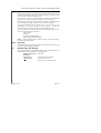
Tellback Received
Inactive
Active
Tellback
received
Code
entered
NOTE: This output is only operative if 'Digi Reply' is programmed as 'Tellback'
- see 9.8.4
Zones Shunted
Inactive
Active
Shunt Zone
closed
Shunt Zone
opened
NOTE: This output will be live when ANY shunt zone is operated, enabling an
indication to be provided to that effect.
Shunt Fault
Inactive
Active
Shunt
Released
Zone(s) now
live
This output will be steady, as shown, if all shunted zones are closed at the
moment that the shunt is released, and will clear after approx. 10 seconds, at
which point the zone(s) become live.
If any zone is in fault condition during that time, the output will PULSE until
cleared, or the shunt is reapplied.
This provides a warning that shunted zones will not be restored to live status
until correctly cleared.
An alternative output - 'Zone Unshunting' - provides the same facility for an
individual zone.
January 2000
Page 29
Castle Care-Tech Ltd.
Aux/ Fire Signal
Active
Inactive
Alarm
NOTES:
Code
Entry
This is the default configuration of Digicom Output No. 1
This output will also trigger if an Auxiliary zone is triggered.
PA Signal
Active
Inactive
Alarm
Reset
NOTE: This is the default configuration for Digi-com Output No. 2
Intruder Signal
Active
Inactive
Alarm
Reset
NOTE: This is the default configuration for Digi-com Output No. 3
Open / Close Signal
Active
Inactive
When first
Area is set
When system
no longer
Fully set.
NOTE: This is the default configuration for Digi-com Output No. 4
Page 30
Issue 3a
2000 Series Diagnostic Alarm System Programming Manual
Trouble Signal
Active
Inactive
Tamper Alarm when unset
OR
Code Entry
Set with omissions
(with Open/Close o/p)
Unset
ALSO active whilst system in Engineering mode
AND during Low Volts fault
NOTE: This is the default configuration for Digi-com Output No. 5
Abort (Mis-Operation) Signal
Active
Inactive
Code Entry
After alarm
Next Code
Entry
NOTE: This is the default configuration for Digi-com Output No. 6
Low Volts Signal
Active
Inactive
Duration of Fault
NOTE: This is the default configuration for Digi-com Output No. 7
This fault will also trigger the 'TROUBLE' output (if programmed).
January 2000
Page 31
Castle Care-Tech Ltd.
Confirmation Signal
Active
Inactive
Code
Entry
At next zone tripped after 'Intruder' o/p
OR
At SECOND zone tripped after ReArm
Output is inhibited for 90 seconds after set, and after
creation of an alarm on entry
NOTE: This is the default configuration for Digi-com Output No. 8
Entry Deviation
Active
Inactive
Alarm caused by
Deviation from
Entry route
Code
Entry
Common Lobby ON
Inactive
Active
As Last Area
on system sets
As First Area
on system Unsets
NOTE: This output is only live if 'Common Lobby' option is programmed as
'ON'
Page 32
Issue 3a
2000 Series Diagnostic Alarm System Programming Manual
Follow Zone
Inactive
Active
Zone opened
Follows Option
Selected
This output permits an indication to be provided as to the state of any individual
zone on the system. When this configuration is selected, the following additional
information is requested:
Output State
[Follow ]
Press YES to have output clear as zone
closes, or NO to change to
[Timed ]
Press YES to have output live for
programmed time; or NO again to change to
[Latched]
Press YES to have output live until another
zone is triggered, and nominate which zone
is to reset the latch
Once this selection has been made, the display will request
Select Zone
to follow [01]
Insert zone number required to follow
If the output was selected as 'Timed,' the required time is then programmed
Output on for
Secs
[000]
Insert the time required, MAXIMUM
setting is 255 seconds.
Zone Unshunting
Inactive
Active
Shunt Released
Zone Now Live
When this configuration is selected, the following additional information is
requested:
Select Zone
to follow [01]
Insert zone number required to follow
This output will be steady, as shown, if the shunted zone is closed at the moment
that the shunt is released, and will clear after approx. 10 seconds, at which point
the zone will become live.
If the zone is in fault condition during that time, the output will PULSE until
cleared, or the shunt is reapplied.
This provides a warning that the shunted zone will not be restored to live status
until correctly cleared.
January 2000
Page 33
Castle Care-Tech Ltd.
Follow Bell
Inactive
Active
Period Bell output is live
Courtesy Lights
Inactive
<Exit Time>
<Entry Time>
Active
Switch
On
9.7.2
Final
Set
Entry
Tone
Unset
Change Standard O/P 1 through 4
This enables the programming of the End Station outputs 1 through 4.
Select with YES and the display with show
Standard O/P 1
VIPER 12v Reset
Pressing the NO key will scroll through the available options (see 9.7.1), and the
YES key will select and move to the next output. The B key will scroll through
the available options backwards.
Page 34
Issue 3a
2000 Series Diagnostic Alarm System Programming Manual
9.7.3
Change Digicom Outputs
This permits the plug-on communicator outputs to be reprogrammed to suit any
individual site requirement.
On Multiple End Station systems, these outputs are live ONLY on End Station
'A'
The default settings are:
Output No.
PIN
No.
Default Assignment
1
2
3
4
5
1
2
3
4
5
6
7
8
Aux/Fire
PA
Intruder
Open/Close
Trouble
Tell Back I/P
Comm Fail I/P
Low Volts
9
10
11
12
13
14
15
16
+12v
0v
Not Used
+5v
Abort (Mis-Operation)
Confirmation
Line Fail I/P
Digicom Reset
7
6
8
Channel
Digi STU
1
1
2
2
3
3
4
4
5 5 or 7
Lo
Lo
Bat Bat
6
7
6
8
8
These may be reprogrammed as follows
Change Digicom
Outputs
Press 'YES'
Digicom o/p 1
Aux/Fire Signal
Press 'NO' to scroll forwards through available
types, or 'B' to scroll backwards
Digicom O/P 1
Area A Alarm
Press 'YES' to accept and move to next output
Digicom O/P 2
P.A. Signal
etc.
A final 'YES' will return to
Change Digicom
Outputs
Press 'NO' to continue
NOTE: In the event of an RS.485 failure whilst the system is set, the End
Station will activate, and trigger outputs on channels 3 and 5 (pins 3 and 5). If
the system is unset, it will activate channel 5 (pin 5) output only.
This will be true regardless of how these output channels are programmed.
January 2000
Page 35
Castle Care-Tech Ltd.
9.7.4
Network Output Modules
To enable additional outputs to be configured, additional modules may be
connected to the RS-485 (Keypad) bus (at any convenient location) to provide
additional outputs
Address Coding
The three address switches provided enable different output configurations to be
used - providing addresses 0 to 7, simply open switches to add up to the number
required. Addresses 8 to 15 (Multiple End Station systems only) are obtained
by using the same addresses with alternative software (version number endorsed
'Address Offset 8') on the output module. Any address configuration may be
repeated as required on additional modules to provide the same outputs at a
different location.
Address locations 0 and 1 select pre-set output configurations, outputs at
addresses 2 to 15 are fully programmable. The same address may be repeated to
provide the same configuration at different locations.
PRE-SET OUTPUT CONFIGURATIONS
Address 0 (basic software, all address switches closed)
Output 1 Sound
Sounder outputs provide loudspeaker
drive duplicating that on the 2000 Series
End Station. Volume control available
2 Sound
on module is NOT under software
control.
3 not used
4 not used
5 Area A Control Area Control outputs enable the sounder
outputs to be routed through the
appropriate Area Control relay to
6 Area B Control
provide sound only in the relevant area.
For example, if output 1 were routed via
the relay of output 5 to a loudspeaker
7 Area C Control located in area A, then exit time when
area A is being set (for example) would
sound in area A, whilst loudspeakers in
8 Area D Control other areas, wired via the other relays,
would remain silent.
Address 1 (basic software, address switch A1 open)
Output 1 Area A Set
2 Area B Set
3 Area C Set
4 Area D Set
These outputs repeat those available on
5 Area A Alarm the 2000 Series End Station
6 Area B Alarm
7 Area C Alarm
8 Area D Alarm
Page 36
Issue 3a
2000 Series Diagnostic Alarm System Programming Manual
PROGRAMMING MODULES ADDRESS 2 AND UPWARDS
Change Output Module Press 'YES'
Module [ - ] Chan [ - ]
Insert address of module to be programmed (eg 2)
Module [ 2 ] Chan [ - ]
Insert output channel on that module (eg 1)
Module [ 2 ] Chan [ 1 ]
No output
Press 'NO' to scroll forwards through available
types, or 'B' to scroll backwards
Module [ 2 ] Chan [ 1 ]
Area B Set
Press 'YES' to accept and move to next output
Module [ - ] Chan [ - ]
Inserting a module number higher than the
maximum (ie 8 for standard system, 16 for
multi-End Station systems) will return to
Change Output
Module
Press 'NO' to continue
9.8
Site Options
9.8.1
Engineer Reset
Engineer Reset
of PA?
Press 'YES' to select
Engineer Reset
of Intruder?
Press 'YES' to select
Engineer Reset
by:
Eng. only
Eng. + Rem
The 'NO' key will toggle between the
options, which are selected using 'YES'
If 'Engineer Reset' is enabled, once an alarm has been generated, the system is
'locked out' until reset. The attendance of an engineer on site is required to reset
the system to its full working state, by entering the engineer code.
If 'Eng. + Rem' has been set, a random 5-digit 'anticode' will be generated by the
system following an alarm, which will be displayed on the keypads. This code
may be referenced to a 'Psion Organiser II' or 'PC' programme to generate a
Remote Reset code which may be entered to perform the reset operation as an
alternative to the attendance of an engineer. The code should be entered whilst
the 'Engineer Reset' message is displayed.
NOTE: Engineer reset is required after an alarm only if the system was 'fully set'
at the time of the alarm, or if any part of the alarm which is set has "Full Alarm"
response valid.
For engineer reset (including Remote reset) to be performed, the area in which
the alarm was created MUST be unset, though other areas may remain set.
January 2000
Page 37
Castle Care-Tech Ltd.
9.8.2
Eng. Reset Time
A timer is provided so that the normal 'Engineer Reset' response may be
cancelled if the alarm is aborted within the filtering period at the Alarm
Receiving Centre.
Engr. Reset Time
Secs
[ 000 ]
Adjust the number of seconds required (max 255), and press YES to confirm.
NOTE: This facility should NOT be used in such a way that Police
attendance could be possible without Engineer Reset being in force.
9.8.3
Dual Trip Fires Confirm
If this option is selected 'ON', a CONFIRMATION signal will be generated
simultaneously with the intruder signal, if the alarm is generated by a pair of
'Dual Trip' zones.
NOTES: The detection configuration of the zone pairing MUST
comply with NACP14 for this option to be used.
This option does NOT appear on the 'System Parameters' printout.
9.8.4
Digi-Reply
Enables signals from communicators to be used:
a) Not Used: Default - use 'NO' key to scroll through alternatives, and 'YES' to
select
b) Tell-back Received: Records (in Trouble Log) acknowledgement from
Central Station of receipt of message from standard Digicom. Also triggers
output (if programmed)
c) RED CARE Reset: Accepts signal from Red Care Central Processor to
perform Engineer Reset of control. Recorded in Trouble Log
9.8.5
Enter Site Code
A code, or description (up to 15 characters) may be entered using the text editor
(see 9.1.4), which will appear on all printouts to distinguish between sites.
9.8.6
Silent Set Menu
If selected, a user, on setting the system, will be presented with the option to
select 'silent set' - in which case it will set without sounding the exit tone.
9.8.7
Omit Zones Menu
If selected, a user, on setting the system, will be presented with the option to
omit individual zones programmed to permit omission.
9.8.8
Areas Selected Menu
If selected, a user, on setting the system, will be presented with the option to
select individual areas, or combinations of areas, whilst setting the system.
Page 38
Issue 3a
2000 Series Diagnostic Alarm System Programming Manual
9.8.9
Common Lobby
If this option is selected as ON, then, when the last programmed area is set, the
system will automatically switch on the 'Common Lobby' area, adding an extra
level of security to those areas already armed.
The first user to unset an area automatically switches off the additional
protection (the Common Lobby) and the system reverts to being area set.
Zones to be allocated to the 'Common Lobby' area should be programmed with
the area assigned as 'COMM' - simply press any of the area keys twice.
The system automatically knows which areas are in use from the zone
programming, so that if, for example, only areas A,B and C are used, the
Common Lobby area will automatically set with the third of these areas.
Care must therefore be taken that all zones of the following types have any
unused areas deleted from their allocation:
24 Hr Tamper
Intruder
Entry Exit (including EE/WT)
Walk Through (including WT/EE)
NOTE: An alarm generated within a 'Common Lobby' area will NOT trigger
any of the 'Area Alarm' outputs.
9.8.10
XDF Filter
This defaults to 'Dynamic' and should NOT be changed unless advised by Castle
Care-Tech Technical Support department.
9.9
Redefine Sign On Message
This function permits the 'System Ready' prompt on the keypad display to be
reprogrammed to show any alternative message required.
January 2000
REDEFINE SIGN ON
MESSAGE
Press YES
Define Sign on:
>System Ready
Programme new text required
(up to 15 characters) as
described at 9.1.4, and press YES.
Page 39
Castle Care-Tech Ltd.
9.10
Change Codes
Selecting this option from the menu allows the engineer to set up the codes that
are used by the customer to control the system.
Change Engineer
Code
( YES allows the Engineer code to be
changed )
Change Operator
Codes
Enter User
No :- [ 01 ]
( Enter the number of the code to be
entered )
Enter User
No :- [ 08 ]
( YES to continue )
User Designator
[ User ]
( Scroll between User, Manager and Duress
by pressing the NO key )
[Manager]
( YES to continue )
Manager
( Press the 4 digit code and YES to
Code [08]= [- - - -]* confirm or NO to enter it again, or 'D' to
DELETE an existing code )
Select Areas:
[ABCD]
Press A,B,C,D to Select areas required,
or to de-select areas previously selected.
To exit, select code number 99, and press YES.
NOTES:
Code No.1 is fixed as a MANAGER code, and cannot be deleted.
* - If the display shows #### than a code is already programmed,
which may be changed, or deleted.
A 'Duress' code may be used to unset the system in the normal
way, but will simultaneously generate a SILENT alarm output.
A 2-key 'PA' facility is permanently available by pressing the '1' and
'7' keys simultaneously. This facility will NOT be available at Slave
Keypads fitted software earlier than 2.6
The Engineer code may be used to set and unset the system for test purposes see 14.1.2. It cannot be used to unset the system after being set by a Manager or
User code. It is not capable of being used for a sequence of area set or unset
operations.
9.11
Remaining Engineer Facilities
are described in section 10 - Engineer Tests and Diagnostics.
Page 40
Issue 3a
2000 Series Diagnostic Alarm System Programming Manual
10
Engineer Tests and Diagnostics
In engineer mode there are two menus devoted to checking the parameters and
functions of the alarm system.
10.1
Engineer Tests
All the outputs from the end station may be tested by simply selecting the
Engineer Tests option from the menu and then switching on the outputs one at a
time as the menu option allows.
ENGINEER TESTS ?
( YES key )
TEST BELL
10.1.1
10.1.2
10.1.3
Bell Test
TEST BELL
(YES key)
TEST Bell
0.5 Amps 13.75v
( NO key ends the test )
TEST BELL
( NO key moves to next test )
Strobe Test
TEST STROBE
(YES key)
TEST STROBE
0.4 Amps 13.75v
( NO key ends the test )
TEST STROBE
( NO key moves to next test )
Sounder Test
TEST SOUNDER
(YES key)
TEST SOUNDER
0.6 Amps 13.50V
( Select '1' key )
TEST SOUNDER 1
0.6Amps 13.50V
Level reduces to 'Low'
Repeat as required, using '2' key for Medium, and '3' key for High
levels to check, and adjust individual sounder levels.
TEST SOUNDER 2
0.6 Amps 13.50V
10.1.4
( NO key moves to next test )
Test Out 1
Each of the four End Station outputs (2300 two only) can be tested, simply by
selecting the appropriate test option.
TEST OUT 1
(YES key)
TEST OUT 1
0.4 Amps 13.75 Amps
( NO key ends the test )
TEST OUT 1
( NO key moves to next test )
Repeat for Outputs 2, 3 and 4
January 2000
Page 41
Castle Care-Tech Ltd.
10.1.5
Test Digi-Comm
This enables the engineer to test each of the outputs to a Digital Communicator
individually:
TEST DIGI-COMM
Press YES key
TEST DIGI-COMM
Press '1' key to initiate test on
channel 1
TEST DIGI-COMM 1
Aux/Fire Signal
type
Note that display shows channel
selected and programmed output
Channels (1 to 8) may be selected, as required, in any order
TEST DIGI-COMM 8
Confirm Signal
Press 'NO' key to move to next
test menu selection
The tests may be conducted with a communicator test pcb (CT5200) fitted, or
with a 'live' communicator.
10.1.6
Test Inputs
Inputs 1, 2 and 3(*) and the communicator inputs may be tested when this
option is selected. Inputs 1, 2 and 3 (*) need to be pulled to 0v to activate.
Communicator inputs can be tripped by pressing the appropriate button on a
2000D test PCB.
(*) - Input 3 is present ONLY on 2700.
Any inputs operated will trigger the internal sounder and be displayed on the
keypad LCD.
TEST INPUTS
(YES key)
Each of the inputs may then be operated. Each successful test will cause the
system to 'chime,' and the inputs will be identified on the keypad, thus:
TEST INPUTS
1 2 Tell CF LF
Press NO to cancel test, and NO again to move to next test.
Page 42
Issue 3a
2000 Series Diagnostic Alarm System Programming Manual
10.1.7
Walk Test
All the detectors on the system may be tested fully in Walk Test without having
to set the system.
WALK TEST
Press 'YES'
OMITTED: - -
Insert the number of a zone to be omitted from the
test, eg 01. The relevant zone text will be displayed,
and await further entries.
OMITTED: - Main Stores
All omitted zones will scroll
Key in the zone number again to remove it from the
omitted list.
Press 'YES' to commence test
WALK TEST 01 The display will scroll through all testable zones on
Front Entrance
the system
As each zone is triggered, the system will 'chime' and
the zone will be removed from the list scrolling, until
All Circuits
Tested
Press NO
Alternatively, the test may be aborted at any time by
pressing the 'NO' key
The option is now available to print a report of the Walk Test
Print Walk Test Press 'YES' to select, or 'NO' to move on
Report
WALK TEST
Printing ....
ENGINEER
TESTS
Press 'NO' to continue
The printout will show the following information:
CASTLE CARE-TECH 2500
v4.1
SITE CODE: J0467-SMITH
DATE: 15/1/00 TIME: 14:37
==========================
WALK TEST REPORT
==========================
Failed Walk Test:
CCT 013
-> Stores
CCT 029 - > Rear Fire Door
OMITTED: 001->Main Entrance
OMITTED: 002->Reception
-------------------------***
END OF REPORT ***
==========================
January 2000
Page 43
Castle Care-Tech Ltd.
10.2
Engineer Diagnostics
2000 Series Controls are unique in their ability to display voltage, current and
resistance readings. The diagnostic facilities are available as reports displayed
on the keypad LCDs or as collated printouts that give a total system diagnostic
report. These diagnostics are designed to improve confidence in the system, and
to simplify faultfinding. They do NOT replace the commissioning readings
required by BS4737.
The diagnostic information available obviously differs according to detection
technology in use.
10.2.1
Multiple End Station Systems
The diagnostic capability is fully available on the multi- ES versions. In the
various test modes, eg Bell Test, Strobe Test the panel will display the current
consumption and the voltage during the test. These facilities are available for
each End Station individually.
Simply press the A, B, C or D key (as appropriate) during an active test and the
area LED will update showing which ES is being communicated with, and the
readings on the display are from that ES.
10.2.2
Zone Condition (2300 and 2700)
Individual circuit information can be displayed on the keypad LCD by selecting
this option.
Display Circuit
Condition ?
( YES key )
The initial display shows the current state of all 16 (2300) or 32 (2700) zones
on the system, in the form of a single character per zone, as follows;
x
=
Closed circuit
O
=
Open circuit
F
=
Circuit fault (tamper open)
h
=
High (incorrect) cable resistance
The display will update in real time as zones are triggered, and will respond
whether or not the zones are programmed.
Multiple End Station systems, press A,B,C,D keys to cycle the display
between the End Station - the keypad LEDs indicate which is current.
Press YES or NO to move to next menu.
Enter Desired
Circuit :[ 01 ]
( Press the NO key to scroll through the
circuit numbers, or press the digits - eg 1
and 3 for circuit 13 and press the YES key)
CCT [13] Voltage
4.39v CC <900 ohms
(Press 'YES' key to step directly to next
circuit, or 'NO' key to return to 'Enter
Desired Circuit' option.)
Key:
CC
Closed Circuit
OC
Open Circuit
CF
Circuit Fault
HR
High (incorrect) resistance
Scroll to end, or select '99' (ie a zone number higher than the maximum possible)
and YES to exit.
Page 44
Issue 3a
2000 Series Diagnostic Alarm System Programming Manual
10.2.3
iD Point Condition (2500 only)
Individual circuit information can be displayed on the keypad LCD by selecting
this option.
Display iD Point
Condition ?
( YES key )
The initial display shows the current state of all 30 zones on the system, in the
form of a single character per zone, as follows;
x
O
F
h
=
=
=
=
Closed circuit
Open circuit
Circuit fault (tamper open)
Twin device (tamper)
The display will update in real time as zones are triggered, and will respond
whether or not the zones are programmed.
Multiple End Station systems, press A,B,C,D keys to cycle the display
between the End Station - the keypad LEDs indicate which is current.
Press YES or NO to move to next menu.
Enter Desired
Circuit : [ 01 ]
( Press the NO key to scroll through the
biscuit numbers or press the digits - eg 1
and 3 for circuit 13 and press the YES key)
iD Point 13
14mA CC
(Press 'YES' key to step directly to next
biscuit, or 'NO' key to return to 'Enter
Desired Circuit' option.)
Key: CC
Closed Circuit
OC
Open Circuit
CF
Circuit Fault
TD
Twin device
Typical current reading will be between 12 and 16mA
Scroll to end, or select '99' (ie a zone number higher than the maximum possible)
and YES to exit
10.2.4
Line Diagnostics (2500 only)
This permits an overall check of the iD line to be made:
Line Diagnostics
[iD Slow Scan]
Press YES to activate (see Wiring manual)
or NO to move to
Line Diagnostics
[Line Current]
Press Yes to read- eg
'iD Point Line 55mA'
or press NO to move to
Line Diagnostics
[Exit]
Press YES to move to next option.
The iD 'Slow Scan Voltages' should be:
Low 2.85; Mid 6.50; and High 11.0
The iD 'Line Current' should be approximately 1.8 mA per device - it is NOT
the sum of the individual biscuit currents displayed at 10.2.3.
January 2000
Page 45
Castle Care-Tech Ltd.
10.2.5
Display Current and Voltage
This option, allows the engineer to perform measurements on the system voltage
and current consumption of the alarm system.
The first display shows the voltage and quiescent current taken by the system
when NO alarm is in operation and no outputs are active.
Display Current
and Voltage?
Current
0.4 A
( YES key )
Volts
13.75V
Pressing the '0' key will toggle the system between quiescent and alarm
modes, so that the alarm current can be noted:
Current
0.9 A
Volts
13.25V
NOTE: Whenever using the system diagnostics to measure current, the
measurement will include any keypad plugged into the engineer keypad socket.
Unplug the engineers keypad to accurately measure the true value.
NOTE: The display will show 'OVERLOAD' in the event of the total system
load exceeding 1.5 amps. If the Voltage shown alongside the Alarm Current is
significantly lower than shown with Standby Current (eg if reading is lower than
12.5 volts), it may indicate that the system is so seriously overloaded that the
system voltage is being pulled down - steps should be taken to check and correct
this condition, as malfunctions may subsequently occur.
Pressing NO will terminate the option.
10.2.6
End Station Faults
This option provides indication of faults in the system Power Supply (Chg.) and
Battery (Bat.) in the following format:
10.2.7
Display End
Station Faults ?
( YES key )
End Stn Faults :[ Chg. Bat.]
( NO key to exit )
Display End
Station Faults ?
( NO key moves to next menu
option)
Earth Leakage (2700 only)
The 2700 only will also show earth leakage faults (including polarity) in the
'End Station Faults' display. This will indicate that a leakage below 1 mega-ohm
exists, whilst the End Station 'Gd' terminal is connected to mains earth.
This fault indication should be ignored if a communicator, or other piece of
equipment, with a direct earth connection, is linked to the system.
Page 46
Issue 3a
2000 Series Diagnostic Alarm System Programming Manual
10.2.8
Print Diagnostics
Selecting this option from the engineer menu will print out the main system
parameters;
Print
Diagnostics ?
( YES key )
after printing,
Print
Diagnostics ?
( NO key moves to next option)
The printout will show the following information:
CASTLE CARE-TECH 2500
v4.1
SITE CODE: J0467-SMITH
DATE: 15/1/00
TIME:
14:45
2500 EndStation Software Version 6.0
MAINS
ON
CHARGER/FUSE
ON
BATTERY/FUSE
ON
BATTERY HEALTH
13.25 VOLTS
SUPPLY VOLTAGE
13.75 VOLTS
QUIESCENT CURRENT
300mA
ALARM CURRENT
0.8 Amps @ 13.50V
From these Current readings
the calculated minimum
Battery Size is 5.6 Amp Hrs
--------------------------------***
END OF REPORT
***
=================================
Battery health is checked by disconnecting the AC supply and running the
system under load on the battery. Should the battery voltage be below 11.25v
the test will abort and indicate 'Fail'.
When measuring current, the keypad backlights will be extinguished to indicate
standby current during mains failure, so producing lower readings than those
displayed.
January 2000
Page 47
Castle Care-Tech Ltd.
10.2.9
Print Circuit Conditions
This option will print out the condition of the circuit inputs on the system. This
is best done with all circuits closed.
Print Circuit
Conditions ?
( YES key )
Circuit Conditions
Printing . . .
The format for this is:
CASTLE CARE-TECH 2500
v4.1
SITE CODE: J0467-SMITH
DATE: 15/1/00
*
TIME:
14:51
LINE CONDITION REPORT
*
CCT I(mA)
COND
---------------------------------01
02
03
04
12
13
12
26
30
00
OK - IN SPEC
OK - IN SPEC
OK - IN SPEC
TWIN DEVICE
etc. to
MISSING
CC
CC
OC
TD
CF
LINE CURRENT (typ 1.8mA/device)35mA
---------------------------------***
END OF REPORT
***
=================================
Or the equivalent for Double Pole / End of Line connections for 2300 and 2700.
The abbreviations used for Circuit Condition are
Page 48
CCT
COND
2300 / 2700
COND
01
CC
Closed Cct
CC
Closed Cct
2500
02
HR
Incorrect
resistance
TD
Twin Device
03
CF
Circuit Fault
CF
Circuit Fault
04
OC
Open Cct
OC
Open Cct.
Issue 3a
2000 Series Diagnostic Alarm System Programming Manual
10.2.10
Print System Parameters
Selecting this option causes the main system parameters to be printed. It takes
the form of :
CASTLE CARE-TECH 2500
v4.1
SITE CODE: J0467-SMITH
DATE:15/1/00 TIME:15.21
=====================
** SYSTEM PARAMETERS **
--------------------CHIME: Single
ON
SYSTEM TIMERS:
Exit Time (secs):
040
Entry Time (secs):
045
etc.
EXIT MODES:
Area Set A :
Area Set B :
Lock Set
Timed
etc.
SOUNDER OPTIONS:
Strobe Confirm Exit: No
Sounder Continues
after Bell Time:
No
etc.
VOLUMES:
Chime:
Fire:
Low
High
etc.
ALARM RESPONSE:
Area A : Full Alarm
Area B : Local Alarm
etc.
STANDARD OUTPUTS:
1 VIPER 12v Reset
2 PIR Latch 1
etc.
DIGICOM OUTPUTS:
1 Aux/Fire Signal
2 P.A. Signal
etc.
iD OUTPUT MODULE:
Output 1 Area A set
etc.
OUTPUT MODULES:
Module 2 Output 1
Courtesy Lights
Module 2 Output 2 Follow
Zone 01
etc.
SITE OPTIONS:
Engineer Reset PA:
OFF
Engineer Reset Int:
ON
etc.
USER CODES:
01 Manager ABCD
02 User
AB
03 User
A C
98 Duress
ABCD
ZONE CONFIGURATION:
CCT 01 : Main Entrance
TYPE: Final Ext/Entry
CCT 02 : Reception
TYPE: Walk Through
A
CCT 02: Sales Office
TYPE: Intruder B
etc.
--------------------*** END OF REPORT ***
=====================
January 2000
Page 49
Castle Care-Tech Ltd.
10.3
Log Review
Selecting this option allows the logs to be reviewed on the keypads.
LOG REVIEW?
YES key
Alarm Log
NO key scrolls to next log
YES key scrolls contents of log on
LCD
Activation Log
NO key scrolls again ....
Trouble Log
NO key exits from option
To view the logs, simply scroll up and down through the events by pressing the
A and C cursor keys.
Where Zone numbers have been replaced by text names, it is the text name that
will be displayed on the LCD.
The log information will be displayed in the following format:
Alarm log:
23/06 23:17:05 →
LOUNGE PIR
This indicates that an alarm was generated by the zone designated 'Lounge PIR'
at 12.17 (and 5 seconds) pm on 23rd June. In this case the additional
information accessed by the 'D' key will show the wiring circuit, or iD biscuit
number - eg
Circuit: 4
Activation log:
23/06 17:24:12 →
ABCD on Key [04]
This indicates that all four areas were set by codeholder number 4 at 5.24 (and
12 seconds) pm on 23rd June. The arrow at top right indicates that additional
information is available by pressing the 'D' key. In this case, it will itemise any
omitted zones.
Printed logs show the YEAR in addition to the information shown above.
Page 50
Issue 3a
2000 Series Diagnostic Alarm System Programming Manual
10.3.1
Print Logs
Selecting this option allows the logs to be printed out, selectively by type, or
date, as follows:
Print Logs
YES to select
Print
[ALARM] Log
Press YES to select, or NO to scroll
through alternatives:
ALARM
ACTIVATION
TROUBLE
ALL
NONE
then YES to select
Print {selected}
Log(s) [Whole]
Press YES to commence printing entire
selected log(s), or NO to select
alternative:
DATE
TO
FROM
EXIT - then YES to select
Print {selected}
Log(s){choice}[_ _ _ _]
Insert date required using numeric keys,
in the format 'ddmm' (eg 2605 = 26th
May), then YES to commence printing of
selected logs.
If 'DATE' is selected, the log(s) will print
for that date only, if 'TO' or 'FROM' is
selected, the log(s) will print INCLUSIVE
of that date.
NOTE: This option is also available from the Manager Menu.
Zone names and numbers will BOTH be printed.
10.3.2
Clear Logs
Simply key in the number 2000 to clear all events from the log.
NOTE: This should be performed ONLY after ensuring that all log information
is no longer required.
It is essential that the logs are cleared before exiting Engineer
menu after the system NVM has been replaced.
January 2000
Page 51
Castle Care-Tech Ltd.
10.4
Exit Engineer Menu
Press 'YES' to return to day mode, or 'NO' five times to scroll around the menu
again (this is designed to prevent overshooting the end of the menu if holding
down the 'NO' key to 'auto-repeat').
At any main menu item (ie with CAPITAL LETTERS), the 'B' key ,may be
used to move backwards through the menus.
The programme information is written to NV memory when the 'Exit Engineer'
option is selected. It is therefore vital that the system is NOT powered down
before this has been completed (ie until 'SYSTEM READY' prompt
displayed, or programmed information will be lost, and existing contents of
memory may be corrupted.
As the system returns to 'day' mode, the message 'Updating NV Memory' will be
displayed, along with an indication of the steps ( 1 to 6 ). If these steps are not
displayed correctly, information has not been correctly updated.
If no NVM is present, the system will continue to function, but will display
'NVM Fault.'
Fast Exit from Engineer Menu
It is possible to exit the Engineer menu at any main menu item. This may be
done by pressing the 'A' key to exit WITHOUT saving any parameters (eg if
only diagnostic features have been used), or the 'C' to exit and SAVE TO NVM.
Any programming changes made will still reside in system memory if the 'A' key
is used, but will NOT be saved to NVM, and hence will be lost if the system is
powered down or re-started.
Tamper Faults on exit from Engineer Menu
If a tamper fault exists at the point of returning to 'day' mode, then, after
updating the NVM, an intermittent tone will sound and the display will identify
the fault. Pressing the 'NO' key without clearing the fault will result in a tamper
alarm. Pressing the 'YES' key will return the system to the Engineer Menu.
The term 'SYSTEM TAMPER' may refer to a BOX tamper, or SAB tamper
fault.
Do NOT power the system down whilst
in Engineering mode.
This will result in failure to save
programmed information, and possible
corruption of data.
Page 52
Issue 3a
2000 Series Diagnostic Alarm System Programming Manual
11
Multi-End Station Systems (2500 and 2700)
11.1
Overview
To cater for the larger site, requiring more zones than the standard system can
monitor, additional End Stations may be added, up to a total of four.
The heart of the system is the Gateway M odule, which contains special
networking software to control all functions of the system. The NVM fitted must
be of type 2465. The Gateway Module plugs directly onto End Station B, C or
D . The four operating areas (A,B,C,D) which the system may be divided into
should NOT be confused with the End Stations. Zones may be assigned to
operating areas in any configuration required, regardless of the End Station
used.
Each End Station must be coded to different communication addresses, by
setting the blue 'dip' switches before powering the system (see 4.1.1). The
number of End Stations in use on the system must be programmed in software refer Section 11.3.1
11.2
Detection Circuits
The available zone (or biscuit) numbers are repeated at each End Station, and
are automatically allocated to the following zone numbers:
End Station
2500
2700
iD biscuits Zone numbers Wiring Cct Zone numbers
'A'
1 - 30
1 - 30
1 - 32
1 - 32
'B'
1 - 30
31 - 60
1 - 32
33 - 64
'C'
1 - 30
61 - 90
1 - 32
65 - 96
'D'
1 - 30
91 - 120
1 - 32
97 - 128
11.3
Programming
All programming functions are exactly as for the corresponding single ES
control, EXCEPT:
11.3.1
Program Valid End Stations
This is the first option available to the Engineer, after 'Clean Start', and enables
the number of End Stations in use to be programmed into the system, thus:
PROGRAM VALID
END STATIONS?
Press YES (#)
Valid End Stns
[ABCD]
Use keys to enter End
Stations which ARE fitted
to system, eg A and B
Valid End Stns
[AB ]
Press Yes to confirm, and
return to
PROGRAM VALID
END STATIONS?
Press No to continue to
next program item.
Upgrading by a further ES simply requires this programming to be adjusted.
January 2000
Page 53
Castle Care-Tech Ltd.
11.3.2
Set Up Communications
The system is ready for connection to a Digi-modem for Downloading, or to a
PC for programming purposes, see 11.4. If these are not used, the 'Comms Uses'
option should be left at 'None.'
The alternative settings ('Modem' and 'Direct') are for use when connected to an
'In-Site' system, full details are shown in the 'In-Site' instruction manual.
11.3.3
Powering up the Multiple End Station System
It is important that the End Station to which the Gateway module is connected
be the last item to power up, or some keypads on the system may not initialise
correctly.
If this is impractical, the Gateway module should be restarted (by shorting
momentarily the R and S pins on the module) after the remainder of the system
is powered.
11.3.4
Faults other than detection circuits
In the event of a fault specific to an ES, (including SAB tamper alarms), the
originating ES (A, B, C or D) will be identified on the display when the system
is silenced, and in the Trouble log.
11.3.5
RS-485 Failures
The failure of one of the ESs will produce a response equivalent to a tamper
fault. The display will identify the failed ES when the alarm is silenced. Note
that the system will indicate, and log, from the point of view of the Gateway
module.
11.4
Programming the system from a PC
The system may be programmed through the Gateway module from a PC fitted
with 'In-Site' software
A plug-on RS-232 assembly (CT5056) should be connected to the Gateway
module. This then connects to a Serial port on the PC.
Setting up the communications from the Engineer menu, and programming from
the PC is described in the 'In-Site' manual.
Page 54
Issue 3a
2000 Series Diagnostic Alarm System Programming Manual
12
DOWNLOADING SYSTEMS
The 2000 Series Controls are compatible with the Castle Care-Tech 'In-Site'
Downloading system. Systems for use in this way should be fitted with special
'Gateway' units combined with 'digi-modems. This enables both communication
with an Alarm Receiving Centre (via the digi-com) and a host PC (via the
modem).
Alternatively, a RedCare 'STU' may be used in the normal way for signalling to
the ARC. To facilitate the connection of the STU on single End Station systems,
the Gateway/Digi-modem unit may be ordered in 'stand-alone' format to
separately housed, whilst the digi-com pins on the End Station are used for the
STU. In the case of multi-End Station systems, the STU should be connected at
End Station 'A' - the controlling Gateway/ digi-modem unit may be plugged onto
any other End Station.
The entire system is programmed from the PC, for full details refer to the
'In-Site' manual. The following information is relevant to the setting up of the
system at the control panel prior to establishing communications with the PC.
12.1
The Digi-Modem (COM 100 or DC58M)
This combines the functions of a Digital Communicator and Modem in a single
package, and communicates with the Gateway unit by an RS.232 link.
12.1.1
Indications
An LED is provided on the digi-modem, giving the following indications:
COM100:
Flashing
Normal condition
Except when dialling
DC58M:
OFF *
Normal condition
Digicom NVM has at least
one number programmed and
system is ready for use.
* - In practice this may be lit very dimly, and pulse off
occasionally.
Digicom NVM is not Normal condition if only the
Flashing
modem section is in use.
approx. 2 per programmed
second
Flashing
Modem section
approx. 4 per dialling out
second
Steady
12.1.2
is Keypad display will show
'phone' with bouncing handset
for same period
Digicom section is Keypad display will show
dialling out
'phone with stationary handset
for same period.
Functions NOT Supported
The following Digi-modem function is NOT currently supported in Castle
'In-Site' systems:
Point ID Extended Format
'Three-way Calling' is supported ONLY when using the DC58M
January 2000
Page 55
Castle Care-Tech Ltd.
12.2
Setting Up at the Control Panel End
12.2.1
Multiple End Station Systems
1 Power up on BATTERY first. In the If the system has previously been
case of a multi-ES system, the ES powered, remove NVM from
with Gateway fitted must be Gateway unit before powering up.
powered up last of all. Then add
mains power.
2 Wait for system to initialise, and
enter Engineer menu
3 With 'Clean Start' on the display, Enter code '2000' when requested.
insert NVM and press YES
4 Scroll with 'NO' to 'Valid End
Stations [ABCD]'
5 Scroll with 'NO'
Communications'
to
'Set
Adjust to show combination in
use, eg [ABC ] and press 'YES'
Up Press 'YES'. Display will change to
'Comms Uses [none]'
6 Use 'NO' to change to 'Comms Uses Display shows
'Downloading
[modem]' and press 'YES.'
Options' - press 'NO'
(Use [Direct] option if setting up for
direct RS.232 link to PC)
7 Press 'NO' display shows 'Change
Modem Options' and press 'YES'
Scroll with 'NO' to 'Change PC
Host Details' and press 'YES'
8 Enter the 'PC Telephone Number' (ie
PC end modem) when requested
Use 'YES' to scroll to 'Set Up Wait for
Communications' then 'NO' to updating
scroll to
'EXIT ENGINEER
MODE' and 'YES' to return to
'System Ready'
NVM
to
complete
9 Check that PC is set up, with 'Wait
for Customer' selected and correct
customer database identified.
10 Press '5555' to initiate call to PC (or
'6666' if second PC being used).
The download of the programmed When this is completed, the system
database will be initiated from the will again Update NVM and show
PC end.
'System Ready'
11 Adjust Manager options as required
( see 12.3) and test system.
12.2.2
Page 56
Single End Station Systems
Issue 3a
2000 Series Diagnostic Alarm System Programming Manual
1
Power up on BATTERY first, then
add mains power
2
Wait for system to initialise, and
enter Engineer menu
Display will show
'Change Panel Options'
With ' Clean Start on the display,
insert NVM, and press YES
Scroll with 'NO' to 'Change Modem
Options'
Scroll with NO to 'Change PC Host
Details'
Enter the 'PC Telephone number' (ie
PC end modem) when requested.
Use 'YES' and 'NO' to answer
options offered whilst scrolling to
'Exit Engineer Menu'
3
4
5
6
7
8
9
10
11
If the system has been
powered before, first
remove NVM from
Gateway unit.
Select with YES
Enter code '2000' when
requested
Select with YES
Select with YES
Select with YES ands
wait for NVM to
complete updating, and
system return to 'System
Ready'
Enter Manager Menu and adjust
options as required (see 12.3)
Check that PC is set up with 'Wait for Customer' selected and
correct customer database identified.
Press '5555' to initiate call to PC
(use '6666' if second PC
is used)
The download of programmed
When this is completed,
information will be initiated by the
the system returns to
PC.
'System Ready' after
updating the NVM.
12
Test system, and make any final
adjustments to Manager menu
options (see 12.3)
12.3
Signalling to the ARC from the Digi-Modem
Programming of the Digi-Com section is done in the same way.
NOTE: If only one ARC telephone and account number are being programmed,
these should NOT be repeated in the 'second' location.
12.4
Additional Programming Options
The following options are available in the MANAGER menu to safeguard the
security of the site. They are NOT accessible via the Engineer menu, or the PC
programme.
January 2000
Page 57
Castle Care-Tech Ltd.
Option
Response if selected as 'yes'
Download in Engineer System must be in Engineer mode before
Download from PC can be initiated
only
Engineer reset may be performed from PC
Remote Reset Option
Isolate Zones Option
Zones may be downloaded from PC as
'Isolated'
Put CCTS on test
Zones attribute 'Soak' may be downloaded
Change User Codes
User Codes may be downloaded from PC
Activate Outputs
System outputs may be activated remotely
from PC diagnostic test routines
Remote Keypad Option
PC may access the system via a simulated
keypad, using standard panel codes
Clear Logs
The logs may be cleared by action from the
PC
View PC Tel Nos.
The PC modem telephone number(s) are
accessible from the PC
Adjust Clock
Clock adjustment may be made from the
PC
Dial In Mode
The Dial In mode may be adjusted from
the PC end.
If these options are selected as 'NO' the facility is blocked at the control, and
access to the PC will be denied or changes ignored as appropriate.
To access these options, enter the MANAGER menu
Scroll with 'NO' to 'Modem Press 'YES'
Options'
Display shows 'Hang Up
Call'
Press 'NO'
Display shows 'Change
Modem Site Options'
Press 'YES', and scroll through the options.
'NO' key changes selection for each item, 'YES'
confirms selection and moves to next item.
On completion, select 'YES' Wait for NVM to update.
to 'EXIT MANAGER
MENU'
NOTE: This information is NOT included in the 2000 Series User Manual
Page 58
Issue 3a
2000 Series Diagnostic Alarm System Programming Manual
13
Notes For Guidance
13.1
Panel Type and Version
Pressing the 'A' key whilst 'System Ready' is shown on the display will cause the
system to display the panel type (2300, 2500 or 2700) and software issue fitted.
13.2
System Measurements
13.2.1
System Voltage
Should be set to 13.75v DC to allow the standby batteries to charge at 13.5v
DC. If set too low the 'charger fault' warning will show. If an adjustment is
necessary to the system voltage, the following steps should be observed:
a) Ensure that quiescent load only is present on the system power supply.
b) Disconnect the system battery.
c) Adjust the control (labelled PSV) very slowly and carefully, measuring
at the battery connections, using a calibrated Digital voltmeter.
d) Reconnect the system battery
It is vital that the battery is disconnected whilst this is being done.
Battery fault indication means the battery is disconnected or discharged at least
3v below system voltage (or fuse fail)
Charger fault indication means the system voltage is below 12v, or the voltage
regulator has failed (or fuse failed)
13.2.2
Current Drain
Typical values for current drain for the 2000 series are:
Mains
On
Mains
Fail
Alarm
End Station plus Master Keypad
Slave Keypad
Remote speaker (16 ohm)
13.2.3
2300
2500
2700
ADD
ADD
210 mA
210 mA
210 mA
140 mA
140 mA
140 mA
160 mA
70 mA
-
200 mA
200 mA
230 mA
140 mA
250mA
Fuses
Mains
Regulator
Battery
Hold Off
Speaker
12v Outlets
iD Line
January 2000
250mA
1.5A
1.5A
800mA
800mA
800mA
160mA
20mm Slow blow
20mm Quick blow
20mm Quick blow
20mm Quick blow
20mm Quick blow
20mm Quick blow
20mm Quick blow
2500 only
Page 59
Castle Care-Tech Ltd.
13.3
Diagnostic Logs
By reading the system logs of historical events it is possible to diagnose
problems simply. All log entries are date and time stamped.
The ALARM LOG records all system full alarms when SET and PA/Fire
Alarms when UNSET. This will include details of the code used to generate a
Keypad Duress Alarm in the form:
DURESS CODE [no ]
The ACTIVATIONS LOG indicates which code holder set or unset the system
and records any Zone omissions.
The TROUBLE LOG contains a comprehensive history of other events,
including
Mains Fail
Mains Restored
Power Supply and Battery Problems
Earth Faults
Daytime Tampers ( Format : Cct Tamper [ no.] )
Engineer Mode Accessed
Telecom Line Fail/Restored
Communicator Fail to Transmit
Code changed
Code deleted
Monitor ON/OFF (Format: Monitor On [no.])
Manager Access
SAB Tamper
Tell Back Rec'd
RED CARE Reset
RS-485 Fail / Recovered
Set Clock to .......
Set Clock from ......
Zone Shunted / Unshunted
Zone Omitted / Readmitted
Soak zone failed [ ]
Masked zone [ ]
Clear Logs
The total number of log entries available within the system memory is 500
events, distributed as follows:
Activation log: 250 events, Alarm log: 100 events, Trouble log: 150 events
13.4
RS-485 Failure
If communications between the master keypad (or Gateway) and end station are
lost (due to cable failure, massive data corruption or insufficient voltage) then
the following indications will occur:
In Day mode the end station will emit intermittent 'bips' and the keypad
will show 'End Station Failure'.
In Armed mode the End Station will signal full alarm.
NOTE the End Station will do this according to factory default communicator
channel information - ie channels 3 and 5 will be triggered.
When communication is restored the system will then function as normal.
Page 60
Issue 3a
2000 Series Diagnostic Alarm System Programming Manual
13.5
Watchdog
Both the end station and keypads have watchdog circuitry to re-start the system
in the event of data corruption or programme failure.
13.6
System Memory
There are two memory provisions in the 2000 control system, both held in the
Master Keypad (or Gateway if used).
One is an E2PROM chip ('NVM') that holds all the major system parameters and
logs. At power up, re-start, or watchdog activation these parameters are
reinstalled in the system memory.
The RAM is used during operation, and does not store any information. The
'BBR' function is NOT now used.
The message 'NVM Fault' refers to the E2PROM not being present in its socket
and thus not storing the system parameters.
13.7
Volume Control
2300
2500
2700
MEDIUM = Adjustable, using control on
pcb labelled:
2
2
1
LOW
1
1
2
HIGH
= Full volume (no adjustment)
= Medium
level
further
adjusted by control labelled:
To simplify the adjustment of Low and Medium volume levels, the 'TEST
SOUNDERS' facility may be used - see 10.1.3
13.8
BABT Approval
2000 Series systems are approved for "indirect" connection to a public
telecommunications system (ie via an approved communicating device) .
Quote Apparatus Approval Number:
13.9
NS/G/23/J/10000
System Paperwork
System paperwork must NOT be left loose in the housing in such a way that it
could constitute a fire hazard.
January 2000
Page 61
Castle Care-Tech Ltd.
14
System Operation
Full details of the operation of the system are provided in the '2000 Series
Diagnostic Alarm Control System Operating Instructions'
14.1
14.1.1
Basic Operation
Setting the System
Check that the display shows 'System Ready.' If a fault message is shown, use
the 'NO' key to scroll till 'System Ready' shows.
Key in the full code (eg 1234):
The display will show;
Leave by Exit
Route
The exit tone will commence and, if programmed for Timed exit, the exit time
will display and count down.
If the facility to 'Select Areas' has been programmed, the display will show:
SELECT AREAS [ABCD]*
To change the areas being set, use the 'A,B,C,D' keys to change the status shown
on the display, then press 'YES'
Once 'YES' key is pressed, the system will commence exit time as above, or
move to next menu, if selected.
SILENT SET?
(YES key if you do not require an exit tone)
OMIT ZONES?
(YES key if you wish to omit a zone)
Leave by Exit
Route
(The exit tone will sound)
Exit the building by the permitted route.
IF A 'PUSH TO SET' BUTTON IS FITTED TO THE SYSTEM, THIS MUST
BE PRESSED ONCE THE FINAL DOOR IS CLOSED. FAILURE TO DO
SO WILL RESULT IN THE SYSTEM NOT SETTING.
SYSTEM READY
When the system is armed the keypad display backlight switches off.
* display will show the maximum areas authorised to be set by the code which
has been entered.
14.1.2
Setting the System with the Engineer Code
The above procedure may be followed using the Engineer code instead of the
user code. In this case, an additional option is presented:
Engineer
Force Arm Test
If selected with YES (#), the system will ignore any zones currently in fault
condition and set. Should any such zone then clear, it will automatically be
admitted to the system. If NO (*) is pressed, the system will set normally.
The engineer code can only unset the system if set by that code.
Page 62
Issue 3a
2000 Series Diagnostic Alarm System Programming Manual
14.1.3
What to do if there is a Fault on Exit
If the 'Force Arm Test' is not used, an open detector will result in the exit tone
becoming interrupted and the display showing the fault - eg:
Cannot Set [02]
HALLWAY
If the fault is part of the exit route (eg hallway PIR detector, or front door),
proceed with the exit procedure, closing all necessary doors on the way out.
The presence of a detector open will automatically extend any programmed exit
time, and prevent the system from setting. When the final door is closed, the tone
will be continuous. Complete the setting procedure, eg pressing a 'Push to Set'
button. The tone will stop. An interrupted tone continuing means that the system
has not set. Re-enter the building, key in the code, and correct the problem.
14.1.4
Unsetting the System
Enter via the authorised entry route, go to the keypad and enter the following
commands whilst the ENTRY TONE continues to sound:
Enter User Code
(Key in the full code - eg 1234)
Unset Areas [ABCD] (YES key)
SYSTEM READY
Alarm system is UNSET.
If the alarm system is PART ARMED when you enter the building:
Enter User Code
(Key in your full code - eg 1234)
UNSET SYSTEM?
(YES key)
Pressing the NO key will provide the option
to set additional areas.
UNSET AREAS:
(Press 'YES' key, or key in areas you wish
[ABCD]
to UNSET - ie what is shown on the
display is what you will unset.)
SYSTEM READY
Alarm system is UNSET
14.1.5
How to Cancel an Alarm
If an alarm occurs during the day (due to wiring failure/ personal attack switch
operated/ fire), go to the nearest keypad and key in the code as requested:
Enter User
(Key in the full code - eg 1234)
Code: - - - First Alarm [xx]
FIRE
If the system alarms whilst the system is set, it will automatically silence as the
system is unset (as above). Should an alarm occur whilst the system is fully set,
it may be silenced by ANY code valid for the system. If the code is not valid for
use with that area, it will remain set, and able to generate a further alarm. If
partially set, the code must be valid for the area in which the alarm occurred.
14.2
Code Guessing Alarm
A Tamper alarm will be generated after thirty keypresses without entering the
correct code.
January 2000
Page 63
Castle Care-Tech Ltd.
14.3
Duress Codes
If a valid 'Duress' code is entered, a SILENT PA alarm will be generated via the
Digital Communicator (if fitted). If this is done during the unsetting process, the
output will take the form of a pulse; if during the set procedure, the output will
remain live until the system is unset.
Additionally, a '2-key PA facility is permanently available at the keypad, by
pressing the '1' and '7' keys simultaneously. This will generate a full 'PA' alarm.
It is NOT possible to programme this facility as 'Silent.' This facility is NOT
available at Slave keypads fitted software prior to issue 2.7
14.4
Keypad Displays
When any keypad on the system is in use, all others will show "SYSTEM IN
USE" and cannot be used. This will clear 10 seconds after the last key entry, or
when the system is returned to 'System Ready'
Unless the mains fails the LCD display backlight will be on all the time that the
panel is in day mode, and during exit and entry time. In the event of mains
failure it will only light during exit/entry and if a key on the keypad is pressed.
When 'Area Set' the light will illuminate immediately any key is pressed,
remaining lit until approx. 10 seconds after the last keypress.
QUICK CHECK SUMMARY
COMMUNICATORS
Ensure correct POLARITY is programmed as well as
correct channels.
POWERING UP
Power up on mains first (except for Down Loading
systems)
Always remove power when connecting communicator or
other additional equipment
Ensure adequate standby battery is correctly connected.
ENGINEERING MODE AND PROGRAMMING
Clean Start before commencing programming
Move forwards with 'NO' ('*') and backwards with 'B'
Allocate Walk Through Zone iD biscuit number next
higher than associated Final Entry Exit zone
Exit with 'A' - with NO save to NVM,
or 'C' - WITH save to NVM
Do NOT power down whilst in Engineer
mode.
Page 64
Issue 3a
INSTRUCT-50
Issue 3a
© Castle Care-Tech Ltd.