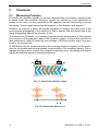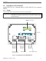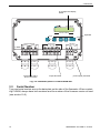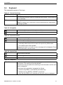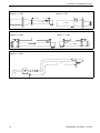
1
User Manual
UMADM5X07-PV1-2EN Standard Design
Ultrasonic Flowmeter
FLUXUS ADM 5107
FLUXUS ADM 5207
Firmware V5.xx
Note:
MS-DOS, Excel, Windows are registered trademarks of Microsoft Corporation.
FLUXUS is a registered trademark of FLEXIM GmbH.
FLEXIM GmbH
Wolfener Strasse 36
12681 Berlin
Germany
Tel.: +49 (30) 936 67 660
Fax: +49 (30) 936 67 680
E-mail: [email protected]
www.flexim.com
User Manual for FLUXUS ADM 5107 and FLUXUS ADM 5207 Standard Design
UMADM5X07-PV1-2EN 01.10.2007
Firmware V5.xx
Copyright (©) FLEXIM GmbH 2007
All rights reserved.
UMADM5X07-PV1-2EN 01.10.2007
Die Sprache, in der die Anzeigen auf dem FLUXUS erscheinen, kann eingestellt werden (siehe Abschnitt 6.3.1).
FLUXUS can be operated in the language of your choice (see section 6.3.1).
Il est possible de sélectionner la langue utilisée par FLUXUS à l'écran (voir
section 6.3.1).
FLUXUS puede ser manejado en el idioma de su elección (ver sección
6.3.1).
UMADM5X07-PV1-2EN 01.10.2007
Table of Contents
1
1.1
Introduction..........................................................................................................7
Regarding this Manual...........................................................................................7
1.2
Safety Precautions.................................................................................................7
2
2.1
Handling ...............................................................................................................9
First Inspection ......................................................................................................9
2.2
General Precautions ..............................................................................................9
2.3
Service...................................................................................................................9
2.4
Cleaning.................................................................................................................9
3
3.1
Flowmeter...........................................................................................................10
Measuring Principle .............................................................................................10
3.2
Description of the Flowmeter ...............................................................................11
3.3
Serial Number......................................................................................................12
3.4
Keyboard .............................................................................................................13
4
4.1
Selection of the Measuring Point .....................................................................14
Acoustic Penetration............................................................................................14
4.2
Undisturbed Flow Profile......................................................................................16
5
5.1
Installation..........................................................................................................19
Location ...............................................................................................................19
5.2
Installation............................................................................................................19
5.3
Connection of the Transducers (terminal strip KL1) ............................................20
5.4
Connection with the Power Supply (terminal strip KL3).......................................22
5.5
Connection of the Outputs (terminal strip KL2)....................................................22
6
6.1
Start-up ...............................................................................................................24
Switching on ........................................................................................................24
6.2
Displays ...............................................................................................................24
6.3
HotCodes.............................................................................................................26
6.4
Interruption of the Power Supply .........................................................................27
7
7.1
Basic Measurement ...........................................................................................28
Input of the Pipe Parameters ...............................................................................28
7.2
Input of the Medium Parameters .........................................................................30
7.3
Other Parameters ................................................................................................32
7.4
Selection of the Channels....................................................................................32
4
UMADM5X07-PV1-2EN 01.10.2007
7.5
Define Number of Sound Paths ...........................................................................33
7.6
Mounting and Positioning the Transducers .........................................................34
7.7
Start of Measurement ..........................................................................................39
7.8
Recognition of Flow Direction ..............................................................................39
7.9
Stopping of Measurement....................................................................................39
8
8.1
Displaying the Measured Values......................................................................40
Selection of the Physical Quantity and of the Unit of Measurement....................40
8.2
Toggling between the Channels ..........................................................................41
8.3
Setting the Display...............................................................................................42
8.4
Status Line...........................................................................................................42
8.5
Transducer Distance............................................................................................43
9
9.1
Advanced Measuring Functions ......................................................................44
Command Execution during Measurement .........................................................44
9.2
Damping Factor ...................................................................................................44
9.3
Totalizers .............................................................................................................45
9.4
Upper Limit of the Flow Velocity ..........................................................................46
9.5
Cut-off Flow .........................................................................................................47
9.6
Calculation Channels...........................................................................................48
9.7
Change of Limit for the Inner Pipe Diameter .......................................................51
9.8
Program Code .....................................................................................................51
10
10.1
Settings...............................................................................................................53
Time and Date .....................................................................................................53
10.2
Dialogs and Menus ..............................................................................................53
10.3
Measurement Settings.........................................................................................55
10.4
Setting the Contrast .............................................................................................56
10.5
Instrument Information.........................................................................................56
11
11.1
SuperUser-Modus..............................................................................................57
Activating/Deactivating ........................................................................................57
11.2
Malfunctions in SuperUser Mode.........................................................................57
12
12.1
Outputs ...............................................................................................................58
Installation of an Output.......................................................................................58
12.2
Error Value Delay ................................................................................................62
12.3
Circuits of the Outputs .........................................................................................63
12.4
Activation of an Analog Output ............................................................................63
UMADM5X07-PV1-2EN 01.10.2007
5
12.5
Activation of a Pulse Output ................................................................................ 64
12.6
Activation of an Alarm Output ............................................................................. 65
12.7
Behavior of the Alarm Outputs ............................................................................ 68
12.8
Deactivating the Outputs ..................................................................................... 70
13
13.1
Troubleshooting ................................................................................................ 71
Problems with the Measurement......................................................................... 72
13.2
Correct Selection of the Measuring Point............................................................ 73
13.3
Maximum Acoustic Contact................................................................................. 73
13.4
Application Specific Problems ............................................................................. 73
13.5
High Measuring Deviations ................................................................................. 74
13.6
Problems with the Totalizers ............................................................................... 75
A
Technical Data ................................................................................................... 76
B
Menu Structure .................................................................................................. 81
C
Reference ........................................................................................................... 89
D
Certificates......................................................................................................... 93
6
UMADM5X07-PV1-2EN 01.10.2007
1 Introduction
1
Introduction
1.1
Regarding this Manual
This manual has been written for the personnel operating the ultrasonic flowmeter FLUXUS. It contains important information on the flowmeter, how to handle it correctly and
how to avoid damages. Always keep this manual at hand.
Get acquainted with the safety rules and the handling precautions. Make sure you have
read and understood this manual before using the flowmeter.
All reasonable effort has been made to ensure the correctness of the content of this manual. If you, however, find some erroneous information, please inform us. We will be grateful for any suggestions and comments regarding the concept and your experience working with the flowmeter.
This will ensure that we can further develop our products for the benefit of our customers
and in the interest of technological progress. If you have any suggestions about improving the documentation and particularly this User Manual, please let us know so that we
can consider your comments for future reprints.
The content of this manual is subject to changes without prior notice. All rights reserved.
No part of this manual may be reproduced in any form without FLEXIM's written permission.
1.2
Safety Precautions
You will find in this manual the following safety information:
Note!
The notes contain important information which help you use the flowmeter optimally.
Attention!
This text contains important instructions which should be respected
to avoid damage or destruction of the flowmeter. Proceed with attention!
This text denotes an action which could result in injury or death of
personal. Proceed with attention!
Respect these safety precautions!
UMADM5X07-PV1-2EN 01.10.2007
7
1 Introduction
1.2.1
Warranty
The FLUXUS flowmeter is guaranteed for the term and to the conditions specified in the
sales contract provided the equipment has been used for the purpose for which it has
been designed and operated according to the instructions given in this User Manual. Misuse of the FLUXUS will immediately revoke any warranty given or implied. This includes:
• replacement of a component of FLUXUS by a component that was not authorized by
FLEXIM
• unsuitable or insufficient maintenance
• repair of FLUXUS by unauthorized personnel
FLEXIM assumes no responsibility for injury to the customer or third persons proximately
caused by the material owing to defects in the product which were not predictable or for
any indirect damages.
FLUXUS is a very reliable instrument. It is manufactured under strict quality control, using modern production techniques. If installed as recommended in an appropriate location, used cautiously and taken care of conscientiously, no troubles should appear.
If any problem appears which can not be solved with the help of this manual (see chapter
13), contact our sales office giving a precise description of the problem. Specify the type,
serial number and firmware version of the flowmeter.
8
UMADM5X07-PV1-2EN 01.10.2007
2 Handling
2
Handling
2.1
First Inspection
The flowmeter has already been tested thoroughly at the factory. At delivery, proceed to
a visual control to make sure that no damage has occurred during transportation.
Check that the specifications of the flowmeter delivered correspond to the specifications
given on the purchase order.
Type and serial number of the flowmeter are given on the data plate on the FLUXUS.
The transducer type is printed on the transducers.
2.2
General Precautions
FLUXUS is a precision measuring instrument and must be handled with care. To obtain
good measurement results and not to damage the flowmeter, it is important to pay great
attention to the instructions given in this user manual, and particularly to the following
points:
• Protect the flowmeter from excessive shock.
• Do not open the housing without authorization.
• Keep the transducers clean. Manipulate the transducer cables cautiously. Avoid excessive cable bend.
• Make sure to work under correct ambient and operating conditions (see annex A Technical Data).
• Take the degree of protection into account (see annex A Technical Data).
2.3
Service
No service work is necessary. Always respect the handling precautions and the instructions given in this manual.
If FLUXUS is installed correctly, in an appropriate location and as recommended, used
cautiously and taken care of conscientiously, no troubles should appear.
Attention!
2.4
Never replace a component of the instrument by parts other than
those supplied by FLEXIM!
Cleaning
• Clean the instrument with a soft cloth. Do not use detergents.
• Remove traces of acoustic coupling compound from the transducers with a soft paper
tissue.
UMADM5X07-PV1-2EN 01.10.2007
9
3 Flowmeter
3
Flowmeter
3.1
Measuring Principle
FLUXUS uses ultrasonic signals for the flow measurement of a medium, employing the
so-called transit time method. Ultrasonic signals are emitted by a first transducer installed on one side of a pipe, reflected on the opposite side and received by a second
transducer. These signals are emitted alternatively in flow direction and against it.
Because the medium in which the signals propagate is flowing, the transit time of the
sound signals propagating in the direction of flow is shorter than the transit time of the
signal propagating against the direction of flow.
The transit-time difference Δt is measured and allows the determination of the average
flow velocity on the propagation path of the ultrasonic signals. A flow profile correction is
then performed in order to obtain the area average of the flow velocity, which is proportional to the volume flow.
FLUXUS tests with its special electronics the incoming ultrasonic signals for their usefulness for the measurement and evaluates the plausibility of the measured values. The integrated microprocessor controls the complete measuring cycle, eliminating disturbance
signals by statistical signal processing techniques.
Fig. 3.1: Path of the ultrasonic signal
t
0
t
1
t
2
Fig. 3.2: Transit time difference Δt
10
UMADM5X07-PV1-2EN 01.10.2007
3 Flowmeter
3 Flowmeter
3.2
Description of the Flowmeter
FLUXUS ADM 5107 has 1 measuring channel. FLUXUS ADM 5207 has 2 measuring
channels.
3.2.1
Design
The front plate has to be removed to access the command panel.
Attention!
The degree of protection of the flowmeter is only guaranteed if the
cable glands are tightly screwed and the front plate is tightly screwed
with the housing.
2x 16-digit LCD display,
backlit
FLU XU S A D M 5107
U L T R A S O N IC F L O W M E T E R
keyboard
R ESTA R T
IN IT
TR A N SD U CER
P R O CESS O U TP U TS
M A R K ED
O R W H IT E
CA B LE
1 0
1 1
B IN A R Y
B 1
B IN A R Y
1 2
1 3
1 4
1
terminals for transducer connection
2
3
B 2
4
CU R R EN T
I1
5
6
P O W ER SU P P LY
O B SER V E LA B EL !
R S485
7
8
P E
9
output terminals
P E
L IN E
N (-)
FU SE
L (+ )
power supply terminals
Fig. 3.3: Command panel of FLUXUS ADM 5107
UMADM5X07-PV1-2EN 01.10.2007
11
3 Flowmeter
2x 16-digit LCD display,
backlit
FLU XU S A D M 5207
1 4
1
U L T R A S O N IC F L O W M E T E R
keyboard
R ESTA R T
IN IT
U L T R A S O N IC T R A N S D U C E R S
CH A N N EL A
=
M A R K ED O R
W H IT E C A B L E
U P
P R O CESS O U TP U TS
CH A N N EL B
D N
U P
B IN A R Y
D N
terminals for transducer connection
B 1
B IN A R Y
B 2
CU R R EN T CU R R EN T
I1
I2
P O W ER SU P P LY
R S485
O B SER V E LA B EL !
P E
L IN E
output terminals
FU SE
power supply terminals
Fig. 3.4: Command panel of FLUXUS ADM 5207
3.3
Serial Number
Type and serial number are on the data plate on the side of the flowmeter. When contacting FLEXIM, always have both numbers and the number of the firmware version at hand
(see section 10.5).
12
UMADM5X07-PV1-2EN 01.10.2007
3 Flowmeter
3 Flowmeter
3.4
Keyboard
The keyboard consists of five keys.
Table 3.1: General functions
ENTER
BRK + C + ENTER
BRK
confirm the selection or the entered value
RESET: Press these three keys simultaneously to recover from an error.
The reset has the same effect as restarting the flowmeter. Stored data will
not be affected.
interruption of the measurement and selection of the main menu
Note: Be careful not to interrupt a current measurement by inadvertently
pressing key BRK!
l
Table 3.2: Navigation
scroll to the right or upwards through a scroll list
scroll to the left or downwards through a scroll list
Table 3.3: Input of numbers
move cursor to the right
scroll through the digits above cursor
C
move cursor to the left. When the cursor is on the left margin:
• an already edited value will be reset to the previously saved value
• an unedited value will be deleted.
If the entered value is not valid, an error message will be displayed. Press
ENTER and enter a correct value.
Table 3.4: Input of text
move cursor to the right
scroll through character set above cursor
C
reset all characters to last saved entry
Table 3.5: Cold start
BRK + C
INIT (cold start): Most parameters and settings are reset to the factory default values. The memory will not be deleted.
Keep the two keys pressed while switching on the flowmeter until the main
menu is displayed.
A cold start during operation is executed as follows:
• Press the keys BRK, C and ENTER simultaneously.
• Release only key ENTER. A RESET is executed.
• Keep the keys BRK and C pressed until the main menu is displayed.
UMADM5X07-PV1-2EN 01.10.2007
13
4 Selection of the Measuring Point
4
Selection of the Measuring Point
The correct selection of the measuring point is crucial for achieving reliable measurement results and a high accuracy. A measurement must take place on a pipe
• where the sound can propagate (see section 4.1) and
• with a fully developed rotationally symmetrical flow profile (see section 4.2).
The correct transducer positioning is an essential condition for error-free measurement. It
guarantees that the sound signal will be received under optimum conditions and evaluated correctly.
Because of the variety of applications and the different factors influencing the measurement, there can be no standard solution for the transducer positioning. The correct position of the transducers will be influenced by the following factors:
• diameter, material, lining, wall thickness and form of the pipe
• medium
• presence of gas bubbles in the medium.
Note!
Avoid measuring points in the vicinity of deformations and defects of
the pipe and in the vicinity of weldings.
Avoid locations where deposits are building in the pipe. Make sure that the ambient temperature at the selected location is within the operating temperature range of the transducers (see annex A Technical Data).
4.1
Acoustic Penetration
It must be possible to penetrate the pipe with acoustic signals at the measuring point.
The acoustic penetration is reached when pipe and medium do not attenuate the sound
signal so strongly that it is completely absorbed before reaching the second transducer.
The attenuation of pipe and medium depends on:
• kinematic viscosity of the medium
• proportion of gas bubbles and solids in the medium
• deposits on the inner pipe wall
• pipe material.
The following conditions have to be respected at the measuring point:
• the pipe is always filled completely
• no solid deposits are building
• no bubbles accumulate.
Note!
Even bubble-free media can form gas pockets when the medium expands, e.g. before pumps and after great cross-section extensions.
Observe the notes in Table 4.1.
14
UMADM5X07-PV1-2EN 01.10.2007
4 Selection of the Measuring Point
Table 4.1: Measuring points to be avoided
Free supply or return pipe section:
Select the measuring point at a pipe location where the pipe can not run empty.
correct
disadvantageous
correct
disadvantageous
Vertical pipe
Select the measuring point at a pipe location where the medium flows upward. The pipe
must be completely filled.
correct
UMADM5X07-PV1-2EN 01.10.2007
disadvantageous
15
4 Selection of the Measuring Point
Table 4.1: Measuring points to be avoided
Horizontal pipe
Select a measuring point where the transducers can be mounted on the side of the pipe,
so that the sound waves propagate horizontally in the pipe. Thus, solids deposited on
the bottom of the pipe and the gas pockets developing at the top will not influence the
propagation of the signal.
correct
4.2
disadvantageous
Undisturbed Flow Profile
Many flow elements (elbows, slide valves, valves, control valves, pumps, reducers, diffusers, etc.) cause a distortion of the flow profile. The axisymmetrical flow profile needed
for correct measurement is no longer given. A careful selection of the measuring point
helps to reduce the impact of disturbance sources.
It is most important that the measuring point is chosen at a sufficient distance from any
disturbance source. Only then it can be assumed that the flow profile in the pipe is fully
developed. However, FLUXUS will give you significant measuring results even under
non-ideal measuring conditions if:
• e.g. a medium contains a certain proportion of gas bubbles or solids or
• the recommended distances to disturbance sources can not be observed for practical
reasons.
Recommended straight inlet and outlet pipe lengths are given for different types of flow
disturbance sources in the examples in Table 4.2.
Table 4.2: Recommended distance from disturbance sources
(D = nominal pipe diameter at the measuring point, L = recommended distance)
disturbance source: 90° elbow
supply: L ≥ 10D
16
return: L ≥ 5D
UMADM5X07-PV1-2EN 01.10.2007
4 Selection of the Measuring Point
disturbance source: 2x 90 ° elbows in one plane
supply: L ≥ 25D
return: L ≥ 5D
disturbance source: 2x 90 ° elbows in different planes
supply: L ≥ 40D
return: L ≥ 5D
disturbance source: T piece
supply: L ≥ 50D
disturbance source: diffuser
supply: L ≥ 30D
UMADM5X07-PV1-2EN 01.10.2007
return: L ≥ 10D
return: L ≥ 5D
17
4 Selection of the Measuring Point
disturbance source: reducer
supply: L ≥ 10D
disturbance source: valve
supply: L ≥ 40D
return: L ≥ 5D
return: L ≥ 10D
disturbance source: pump
supply: L ≥ 50D
18
UMADM5X07-PV1-2EN 01.10.2007
5 Installation
5
Installation
5.1
Location
Select the measuring point according to the recommendations in chapter 4 and make
sure that the ambient temperature is within the operating temperature range of the transducers (see annex A Technical Data).
Select the location of the flowmeter within cable reach of the measuring point. Make sure
that the ambient temperature is within the operating temperature range of the flowmeter
(see annex A Technical Data).
5.2
Installation
• Remove the front plate from the housing of the flowmeter.
• Drill four holes in the wall at the selected location (see Fig. 5.1 or Fig. 5.2).
• Insert dowels in the holes and fix the housing with screws in the wall.
103
140
165
Ø 8.4
Ø 4.5
3x M20 x 1.5
180
71
Fig. 5.1: Dimensions of FLUXUS ADM 5107 (in mm)
UMADM5X07-PV1-2EN 01.10.2007
19
Ø 4.5
103
140
205
Ø 8.4
5 Installation
71
220
Fig. 5.2: Dimensions of FLUXUS ADM 5207 (in mm)
5.3
Connection of the Transducers (terminal strip KL1)
Note!
It is recommended to run the cables from the measuring point to the
flowmeter before the connection of the transducers to avoid load on
the connectors.
Note!
The degree of protection of the flowmeter is only guaranteed if the
cable glands are tightly screwed and the front plate is tightly screwed
with the housing.
Connecting the Transducer Cable to the Flowmeter
• Prepare the connection cable as shown in Fig. 5.4.
• Remove the outer left blind plug from the housing (see Fig. 3.3 or Fig. 3.4).
• Open the cable gland (see Fig. 5.3). The compression part (2) remains in the cap nut
(1).
( 1 )
( 2 )
( 3 )
Fig. 5.3: Cable gland: cap nut (1), compression part (2), basic part (3)
20
UMADM5X07-PV1-2EN 01.10.2007
5 Installation
the rim of the compression part
is flush with the outer cable
sheath.
7 m m
2 5 m m
2 0 m m
4 5 m m
Fig. 5.4: Connection of the transducers to the flowmeter
• Press the cap nut (1) with the compression part (2) on the cable until the thin rim of the
compression part is flush with the outer cable sheath (see Fig. 5.4 and Fig. 5.3).
• Cut the outer shield of the transducer cable and brush it back.
Note!
For good high frequency shielding it is important to assure good contact between the cable shield and the cap nut (and thus the housing).
• Screw the basic part (3) with the housing.
• Insert the end of the transducer cable with the uninsulated leads in the housing.
• Fix the cable gland by screwing the cap nut (1) on the basic part (3).
• Connect the leads to the terminals of the flowmeter (see Fig. 5.5 or Fig. 5.6).
1 0
1 1 1 2
1 3
1 4
Fig. 5.5: Connection of the transducer cable with FLUXUS ADM 5107
1 U +
1 U -
1 D - 1 D +
2 U +
2 U -
2 D - 2 D +
Fig. 5.6: Connection of the transducer cable with FLUXUS ADM 5207
UMADM5X07-PV1-2EN 01.10.2007
21
5 Installation
5.4
Connection with the Power Supply (terminal strip KL3)
Install an external safety switch so that the power supply of the flowmeter can be interrupted rapidly at any time. The switch must be located near the flowmeter. Use a switch with appropriate disconnection effect.
• Prepare the power cable with a M20 cable gland.
• Remove the outer right blind plug from the housing (see Fig. 3.3 or Fig. 3.4).
• Screw the gasket ring side of the basic part (3 in Fig. 5.3) in the housing.
• Push the cable through the basic part (3) in the housing.
• Fix the cable gland by screwing the cap nut (1) on the basic part (3).
• Connect the leads to the terminals of the flowmeter (see Table 5.1).
Table 5.1: Connection with the power supply
Terminal
connection AC
PE
earth
N(-)
neutral
L(+)
Phase 100...230 V AC, 50/60 Hz
5.5
connection DC
earth
- DC
+ DC
Connection of the Outputs (terminal strip KL2)
• Prepare the output cable with a M20 cable gland.
• Remove the second filler plug on the right from the housing (see Fig. 3.3 or Fig. 3.4).
• Screw the gasket ring side of the basic part (3 in Fig. 5.3) in the housing.
• Push the cable through the basic part (3) in the housing.
• Fix the cable gland by screwing the cap nut (1) on the basic part (3).
• Connect the leads to the terminals of the flowmeter (see Table 5.2 or Table 5.3).
Attention!
22
The degree of protection of the flowmeter is only guaranteed if the
cable glands are tightly screwed and the front plate is tightly screwed
with the housing.
UMADM5X07-PV1-2EN 01.10.2007
5 Installation
Table 5.2: Connection of the outputs of FLUXUS ADM 5107
terminal
1, 2
3, 4
5, 6
7
8
9
connection
binary output B1
binary output B2
current output I1
-
Table 5.3: Connection of the outputs of FLUXUS ADM 5207
terminal
1, 2
3, 4
5, 6
7, 8
9
10
11
connection
binary output B1
binary output B2
current output I1
current output I2
-
Table 5.4: Default settings of the outputs of FLUXUS ADM 5107
output
source channel
source item
measured value
output range
error output
current output I1
A
measured value
physical quantity
4...20 mA
3.5 mA
Table 5.5: Default settings of the outputs of FLUXUS ADM 5207
output
source channel
source item
measured value
output range
error output
current output I1
A
measured value
physical quantity
4...20 mA
3.5 mA
current output I2
B
measured value
physical quantity
4...20 mA
3.5 mA
These settings can be changed. For installation of the outputs see section 12.1. For the
activation of the outputs see section 12.4...12.6.
UMADM5X07-PV1-2EN 01.10.2007
23
6 Start-up
6
Start-up
6.1
Switching on
FLEXIM FLUXUS
ADM5X07-25X00100
As soon as the power supply is connected to the flowmeter, the serial number of the flowmeter is displayed for a
short time.
Data can not be entered while the serial number is displayed.
>PAR< mea opt sf
Parameter
6.2
Displays
6.2.1
Main Menu
>PAR< mea opt sf
Parameter
After initialization, the main menu is displayed in the selected language. The language of the display can be set
(see section 6.3.1).
The main menu contains the program branches:
• PAR (Parameter)
• MEA (Measuring)
• OPT (output options)
• SF (special functions)
The selected program branch is displayed in capital letters between arrows. The full
name of the selected program branch is displayed in the lower line.
Use key
and
to select a program branch. Press ENTER.
Note!
By pressing key BRK, the measurement will be stopped and the main
menu selected.
Note!
In this manual, all program entries and keys are indicated in capital
letters. Program entries are indicated in typewriter characters (PARAMETER).
The menu items will be separated from the main menu by a backslash "\".
24
UMADM5X07-PV1-2EN 01.10.2007
6 Start-up
6.2.2
The Program Branches and their Menu Items
• The pipe and medium parameters will be input in the program branch PARAMETER.
• The steps for the measurement will be processed in the program branch MEASURING.
• Physical quantity with unit of measurement and all parameters necessary for the measured value output will be defined in the program branch OUTPUT OPTIONS.
• All functions that are not directly related with the measurement are in the program
branch SPECIAL FUNCTION.
For an overview of the program branches see section 6.2.3. For a detailed overview of
the menu structure see annex B.
6.2.3
1
Overview of the Program Branches
Parameter
Measuring
Output Options
Special Function
>PAR<
>MEA<
>OPT<
>SF<
↓
↓
↓
↓
selection of the
measuring channel
selection of the
measuring channel
selection of the
measuring channel
system
settings1)
↓
↓
↓
↓
pipe parameters
sound path
physical quantity
instrument
information
↓
↓
↓
↓
medium parameters
transducer
positioning
unit of
measurement
program code
↓
↓
↓
extension cable
measurement
damping
↓
↓
consistency check
measured value
output
The following menu items are in SYSTEM SETTINGS:
• dialogs/menus
• measurement
• outputs
• Miscellaneous
• set clock
UMADM5X07-PV1-2EN 01.10.2007
25
6 Start-up
6.2.4
Navigation
If a vertical arrow
is displayed, the menu item contains a scroll list. The current list
item is displayed in the lower line.
Parameter
for Channel
A:
Scroll with key
and
line. Press ENTER.
to select a list item in the lower
In some menu items, there is a horizontal scroll list in the lower line. The selected list
item is displayed between arrows.
Lining
no
>YES<
Scroll with key
and
line. Press ENTER.
to select a list item in the lower
In some menu items, there is a horizontal scroll list in the upper line. The selected list
item is displayed in capital letters between arrows. The current value of the list item is
displayed in the lower line.
R1=FUNC<typ mode
Function:
MAX
Scroll with key
to select a list item in the upper line.
Scroll with key
to select a value for the selected list
item in the lower line.
Press ENTER.
6.3
HotCodes
A HotCode is a key sequence activating some settings:
• language selection (see section 6.3.1)
• switching on the SuperUser mode (see chapter 11)
• manual input of the lower limit for the inner pipe diameter (see section 9.7)
SYSTEM settings
Miscellaneous
Input a HOTCODE
no
>YES<
Please input a
HOTCODE: 000000
INVALID HOTCODE
HOTCODE: 000000
Input a HOTCODE
no
>YES<
26
Select SPECIAL FUNCTION\SYSTEM SETTINGS\MISCELLANEOUS.
Select YES to enter a HotCode.
Enter the HotCode. Press ENTER.
An error message will be displayed if a HotCode not valid
is entered. Press ENTER.
Select YES to enter the HotCode again or NO to return the
menu item MISCELLANEOUS.
UMADM5X07-PV1-2EN 01.10.2007
6 Start-up
6.3.1
Language Selection
FLUXUS can be operated in the languages listed below. The language can be selected
with the following HotCodes:
Table 6.1: Language HotCodes
909031
909033
909034
909044
909049
Dutch
French
Spanish
English
German
Depending on the technical data of the flowmeter, some of the languages might not be
implemented.
When the last digit is entered, the main menu will be displayed in the selected language.
The selected language remains activated after switching the flowmeter off and on again.
The language can be selected as often as required.
Note!
6.4
After initializing of the flowmeter (keys BRK and C during switching
on), the display will be indicated in the factory preset language.
Interruption of the Power Supply
All current measuring parameters will be stored in a non-volatile cold start resistant
EPROM as soon as the measurement begins. The operation of the flowmeter will be interrupted if the power supply fails. All input data are preserved.
FLEXIM FLUXUS
ADM5X07-25X00100
After return of the power supply, the serial number will be
displayed for a few seconds.
The interrupted measurement will be continued. All selected output options are still active.
The flowmeter does not continue the measurement after return of the power supply if a
cold start was performed.
UMADM5X07-PV1-2EN 01.10.2007
27
7 Basic Measurement
7
Basic Measurement
The pipe and medium parameters will be entered for the selected measuring point (see
chapter 4). The ranges are limited by the characteristics of the transducers and of the
flowmeter. An error message will be displayed if the limits are exceeded (MINIMUM and
MAXIMUM plausibility check).
7.1
Input of the Pipe Parameters
Outer Diameter
1100.0
MAXIMAL
The entered outer diameter in the example is too high.
The upper limit of this parameter is displayed.
example: 1100.0 mm for the connected transducers and
for a pipe wall thickness of 50 mm.
Note!
The parameters will be stored only if the program branch PARAMETER is finished completely once.
>PAR< mea opt sf
Parameter
Parameter
for Channel
A:
Select the program branch PARAMETER. Press ENTER.
Select the channel for which parameters are to be entered. Press ENTER.
This display will not be indicated, if the flowmeter has
only one measuring channel.
7.1.1
Outer Pipe Diameter/Pipe Circumference
Outer Diameter
100.0
mm
Note!
Enter the outer pipe diameter. Press ENTER.
If the entered outer diameter is > 4000 mm, only a measurement in
diagonal mode will be possible (see section 7.5).
It is possible to enter the pipe circumference instead of the outer pipe diameter (see section 10.2.1). The setting is cold start resistant. It will be activated in the program branch
SPECIAL FUNCTION.
If the input of the pipe circumference has been activated and 0 (zero) is entered for the
OUTER DIAMETER, the menu item PIPE CIRCUMFER. will be displayed automatically. If
the pipe circumference is not to be entered, press key BRK to return to the main menu
and start the parameter input again.
28
UMADM5X07-PV1-2EN 01.10.2007
7 Basic Measurement
7.1.2
Pipe Wall Thickness
Wall Thickness
3.0
mm
Note!
Enter the pipe wall thickness. The range depends on
the connected transducers. Default is 3.0 mm. Press
ENTER.
The inner diameter (= outer diameter - 2x pipe wall thickness) will be
calculated internally. If the value is not within the inner pipe diameter
range of the connected transducers, an error message will be displayed.
It is possible to change the lower limit of the inner pipe diameter for a
given transducer type (see section 9.7).
7.1.3
Pipe Material
The pipe material has to be selected to determine the sound velocity. The sound velocities for the materials in the scroll list are stored in the flowmeter.
Select the pipe material from the scroll list.
Pipe Material
Carbon Steel
If the material is not in the scroll list, select OTHER MATERIAL. Press ENTER.
When the pipe material is selected, the corresponding sound velocity is set automatically. If OTHER MATERIAL is selected, the sound velocity has to be entered.
c-Material
3230.0
Note!
Enter the sound velocity of the pipe material.
m/s
Values between 600.0 m/s and 6553.5 m/s will be accepted. Press ENTER.
Enter the sound velocity of the material (i.e. longitudinal or transversal velocity) which is nearer to 2500 m/s.
For the sound velocity of some materials see annex C, Table C.1.
7.1.4
Pipe Lining
Lining
no
>YES<
If the pipe has an inner lining, select YES. Press ENTER.
If NO is selected, the next parameter will be displayed
(see section 7.1.5).
lining
Bitumen
UMADM5X07-PV1-2EN 01.10.2007
Select the medium from the scroll list.
If the material is not in the scroll list, select OTHER MATERIAL. Press ENTER.
29
7 Basic Measurement
If OTHER MATERIAL is selected, the sound velocity has to be entered.
c-Material
3200.0
m/s
Enter the sound velocity of the lining material. Values
between 600.0 m/s und 6553.5 m/s will be accepted.
Press ENTER.
For the sound velocity of some materials see annex C, Table C.1.
Liner Thickness
3.0
mm
Note!
7.1.5
Enter the thickness of the liner. Default is 3.0 mm.
Press ENTER.
The inner diameter (= outer diameter - 2x pipe wall thickness - 2x liner thickness) will be calculated internally. If the value is not within the
inner pipe diameter range of the connected transducers, an error
message will be displayed.
Pipe Roughness
The flow profile of the medium is influenced by the roughness of the inner pipe wall. The
roughness will be used for the calculation of the profile correction factors. As the pipe
roughness can not be exactly determined in most cases, it has to be estimated.
For the roughness of some materials see annex C, Table C.2. The values are based on
experience and measurements.
Roughness
0.4
mm
Enter the ROUGHNESS for the selected pipe or lining material.
Values between 0.0 mm and 5.0 mm will be accepted.
Default for steel as pipe material is 0.1 mm.
Change the value according to the condition of the inner
pipe wall. Press ENTER.
7.2
Input of the Medium Parameters
Medium
Water
Select the medium from the scroll list.
If the medium is not in the scroll list, select OTHER MATERIAL. Press ENTER.
If a medium is selected from the scroll list, the menu item for the input of the medium
temperature will be displayed directly (see section 7.2.4).
If OTHER MEDIUM is selected, the medium parameters have to be entered first (see the
following sections):
• min. and max. sound velocity
• kinematic viscosity
• density
30
UMADM5X07-PV1-2EN 01.10.2007
7 Basic Measurement
7.2.1
Sound Velocity
The sound velocity of the medium is used for the calculation of the transducer distance at
the beginning of the measurement. However, the sound velocity does not influence the
measuring result directly. Often, the exact value of the sound velocity for a given medium
is unknown. A range of possible values for the sound velocity must therefore be entered.
These displays are indicated only if OTHER MEDIUM has been selected.
c-Medium
1400.0
7.2.2
MIN
m/s
Enter the min. and max. sound velocity of the medium.
Values between 500.0 m/s and 3500.0 m/s will be accepted. Press ENTER after each input.
Kinematic Viscosity
The kinematic viscosity influences the flow profile of the medium. The entered value and
other parameters will be used for the profile correction. This display is indicated only if
OTHER MEDIUM has been selected.
Kinem. Viscosity
1.00
mm2/s
7.2.3
Enter the kinematic viscosity of the medium. Values between 0.01 mm2/s and 30 000.00 mm2/s will be accepted. Press ENTER.
Density
The density of the medium has to be entered. The mass flow will be calculated on the basis of the density (product of volume flow and density). This display is indicated only if
OTHER MEDIUM has been selected.
Note!
If the mass flow is not measured, press ENTER. The other measuring results will not be influenced.
Density
1.00
7.2.4
Enter the operating density of the medium.
g/cm3
Values between 0.01 g/cm3 and 20.00 g/cm3 will be accepted.
Medium Temperature
The medium temperature is used for the interpolation of the sound velocity and for the
calculation of the recommended transducer distance at the beginning of the measurement.
During measurement, the medium temperature will be used for the interpolation of density and viscosity of the medium.
Medium Temperat.
20.0
C
UMADM5X07-PV1-2EN 01.10.2007
Enter the medium temperature. The value must be
within the operating temperature range of the transducers. Default is 20 °C. Press ENTER.
31
7 Basic Measurement
7.3
Other Parameters
7.3.1
Cable Length
If the transducer cable has to be extended, enter the
additional cable length (e.g. between the junction box
and the flowmeter). Press ENTER.
Additional cable
65.0
m
7.4
Selection of the Channels
The channels on which will be measured can be activated individually. This is only possible if the flowmeter has more than one measuring channel.
Select the program branch MEASURING. Press ENTER.
par >MEA< opt sf
Measuring
If this error message is displayed, the parameters are
not complete. Enter the missing parameters in the program branch PARAMETER.
par >MEA< opt sf
NO DATA
!
The channels for the measurement can be activated
and deactivated.
KANAL: >A< B Y Z
MESSEN
- .
This display will not be indicated, if the flowmeter has
only one measuring channel.
The symbols mean:
: the channel is active
–: the channel is not active
•: the channel can not be activated
Note!
A measuring channel can not be activated if the parameters are not
valid, e.g. if the parameters in the program branch PARAMETER of the
channel are not complete.
• Select a channel with key
• Press key
.
to activate or deactivate the selected channel.
• Press ENTER.
A deactivated channel will be ignored during the measurement. Its parameters will remain unchanged.
32
UMADM5X07-PV1-2EN 01.10.2007
7 Basic Measurement
7.5
Define Number of Sound Paths
The sound path is the number of the transits of the ultrasonic waves through the medium
in the pipe.
At an odd number of transits (diagonal mode), the transducers will be mounted on opposite sides of the pipe.
At an even number of transits (reflection mode), the transducers will be mounted on the
same sides of the pipe.
diagonal mode, number of sound paths = 3
reflection mode, number of sound paths = 2
A
A
!
A < 0
diagonal mode, number of sound paths = 1, negative transducer distance
Fig. 7.1: Sound path and transducer distance (A)
An increased number of transits means increased accuracy of the measurement. However, the increased transit distance leads to a higher attenuation of the signal. The reflections on the opposite pipe wall and deposits on the inner pipe wall cause additional amplitude losses of the sound signal.
If the signal is attenuated strongly by the medium, the pipe, deposits, etc., the number of
sound paths has to be set to 1 if necessary.
Note!
Correct positioning of the transducer is easier for an even number of
transit paths than for an odd number.
A: Sound Path
4
NUM
UMADM5X07-PV1-2EN 01.10.2007
A value for the number of sound paths corresponding to
the connected transducers and the entered parameters
will be recommended. Change the value if necessary.
Press ENTER.
33
7 Basic Measurement
7.6
Mounting and Positioning the Transducers
7.6.1
Transducer Distance
Transd. Distance
A:54 mm Reflec
A value for the transducer distance will be recommended. Mount the transducers on the pipe adjusting
this value (see section 7.6.2). Press ENTER.
A - measuring channel
REFLEC - reflection mode
DIAGON - diagonal mode
The transducer distance given here is the distance between the inner edges of the transducers. A negative transducer distance is possible for a measurement in diagonal mode
on very small pipes (see Fig. 7.1).
Note!
7.6.2
The accuracy of the recommended transducer distance depends on
the accuracy of the pipe and medium parameters entered.
Mounting the Transducers
The transducer will be mounted that the engravings on the transducers form an arrow
(see Fig. 7.2). The arrow does not need to show in flow direction (see section 7.8). The
transducer cables show then in opposite directions.
Note!
The engravings should also form an arrow if the transducers are
mounted on opposite sides of the pipe.
Fig. 7.2: Correct positioning of the transducers (A = transducer distance)
34
UMADM5X07-PV1-2EN 01.10.2007
7 Basic Measurement
7
Basic
Measurement
The
transducers
will be fixed to the pipe by means of the supplied transducer mounting
fixture.
Rust, paint or other deposits on the pipe will absorb the sound signal. To reach a maximum acoustic contact between pipe and transducers, the measuring point as to be prepared as follows:
• Clean the pipe at the transducer positions.
• Remove rust or loose paint.
• An existing paint layer on the pipe should be sanded for a better measuring result.
• Use coupling foil or apply a bead of acoustic coupling compound along the center line
onto the contact surface of the transducer. Do not spread the acoustic coupling compound on the contact surface, but press the transducer on the pipe at the measuring
point.
• There should be no air pockets between transducer contact surface and pipe wall.
Make sure that the transducer mounting fixture applies the necessary pressure on the
transducers.
7.6.3
Mounting the Transducers with Transducer Shoes and Tension
Straps
• Cut the tension straps (pipe circumference + 120 mm).
• Make sure that part (2) of the clasp is on top of part (1) (see Fig. Fig. 7.3). The hooks of
part (2) must be on the outer side of the clasp.
• Pull approx. 2 cm of the tension strap through the slot of the clasp (see Fig. 7.4) to fasten the strap to the clasp.
• Bend the strap end back to fasten the strap to the clasp. Guide the free end of the tension strap through the groove on the top of the transducer shoe.
• Place the clasp on the side of the pipe just in front of you. Lay the tension strap around
the pipe (see Fig. 7.5).
• Place the transducer shoe on the pipe. Hold clasp and transducer shoe with one hand
while pushing the tension strap through parts (2) and (1) of the clasp (see Fig. 7.3).
• Pull the tension strap firmly and engage it in the inner hooks of the clasp.
Fig. 7.3: Clasp
Note!
At pipes with large diameters, use tongs, if necessary, to tense the
tension strap.
UMADM5X07-PV1-2EN 01.10.2007
35
7 Basic Measurement
Note!
The clasp must be completely in contact with the pipe to ensure a
good fixation.
Fig. 7.4: Clasp with tension strap
• Mount the second transducer shoe in the same way adjusting the displayed transducer
distance by means of the measuring tape.
• Tighten the screws of the clasps.
• Push the transducers in the transducer shoes. Press the transducer firmly on the pipe.
There should be no air pockets between transducer surface and pipe wall. Tighten the
screw of the transducer shoe firmly.
Note!
When the transducers are mounted on a vertical pipe and FLUXUS is
placed lower than the pipe, the cable of the upper transducer should
be fixed by a cable tie to the tension strap to protect the cable from
mechanical strain.
Fig. 7.5: Mounted transducer in transducer shoe
36
UMADM5X07-PV1-2EN 01.10.2007
7 Basic Measurement
7 Basic Measurement
7.6.4
Fine Adjustment of the Transducer Distance
Transd. Distance
A:54 mm Reflec
If the displayed transducer distance is adjusted, press ENTER.
The positioning procedure is started.
S=
A: <> =54
mm!
A bar graph S= displays the amplitude of the received signal.
Shift the transducer slightly in the range of the recommended transducer distance until the bar graph has max.
length (max. 6 squares)
By scrolling with key
through the upper line and with
key
through the lower line
S=
Q=
• transducer distance
• bar graph Q= (signal quality), must have max. length
trans.
Q=
94.0 μs
• transit time TRANS. in microseconds
• bar graph S= (signal amplitude)
can be displayed.
If the signal is not sufficient for measurement, Q= UNDEF
will be displayed.
In case of larger deviations, check if the entered parameters are correct or repeat the
measurement at a different location on the pipe.
Transd.Distance?
53.9
mm
After the precise positioning of the transducers, the recommended transducer distance is displayed again.
Enter the actual (precise) transducer distance. Press ENTER.
Repeat the steps for all channels on which will be measured. The measurement will be
started automatically afterwards.
7.6.5
Consistency Check
If a wide range for the sound speed has been entered in the program branch PARAMETER
or the exact parameters of the medium are not known, a consistency check is recommended.
The transducer distance can be displayed during measurement by scrolling with key
L=(50.0) 54.0 mm
54.5
m3/h
UMADM5X07-PV1-2EN 01.10.2007
.
In the upper line, the optimum transducer distance is displayed in parentheses (here: 50.0 mm), followed by the
entered transducer distance (here: 54.0 mm). The latter
value must correspond to the actually adjusted transducer
distance. Press ENTER to optimize the transducer distance.
37
7 Basic Measurement
The optimum transducer distance is calculated on the basis of the measured sound
speed. It is therefore a better approximation than the first value which had been calculated on the basis of the approximate sound speed range entered in the program branch
PARAMETER.
If the difference between optimum and entered transducer distance is less than given in
Table 7.1, the measurement is consistent and the measured values are valid. The measurement can be continued.
If the difference is greater, adjust the transducer distance to the displayed optimum value. Afterwards, check the signal quality and the signal amplitude bar graph (see section
7.6.4). Press ENTER.
Table 7.1: Standard values for signal optimization during consistency check
transducer type
Q
M
difference between optimum and actual transducer distance
< 6 mm
< 10 mm
Transd.Distance?
50.0
mm
L=(51.1) 50.0 mm
54.5
m3/h
Note!
Enter the new adjusted transducer distance. Press ENTER.
Scroll with key
again until the transducer distance is
displayed and check the difference between optimum and
adjusted transducer distance. Repeat the steps if necessary.
Never change the transducer distance during measurement without
having restarted the consistency check!
Repeat the steps for all channels on which will be measured.
7.6.6
Value of the Sound Speed
The sound velocity of the medium can be displayed during measurement by pressing key
.
If an approximate range for the sound speed has been entered in the program branch
PARAMETER and the transducer distance has been optimized afterwards as described in
section 7.6.5, it is recommended to note the sound velocity for the next measurement.
The optimization procedure does not need to be repeated then.
Also take note of the temperature of the medium as the sound speed depends on the
temperature. The value can be entered in the program branch PARAMETER.
38
UMADM5X07-PV1-2EN 01.10.2007
7 Basic Measurement
7.7
Start of Measurement
A:Volume Flow
31.82
m3/h
The measured values will be displayed in the lower line.
Press ENTER to return to the fine adjustment of the transducer distance (see section 7.6.4).
If more than one measuring channel is available/activated, the flowmeter works with an
integrated measuring point multiplexer providing quasi simultaneous measurement on
the different measuring channels. The flow is measured on one channel for approx. 1
second, then the multiplexer switches to the next activated channel. The measuring time
depends on the measuring conditions. If, e.g. the measuring signal can not be detected
immediately, the measurement might take longer than 1 second.
The results are displayed according to the actually selected output options (see chapter
8). The default unit of measurement for the volume flow is m3/h. The selection of the values to be displayed and the setting of the output options are described in chapter 8. Advanced measuring functions are described in chapter 9.
7.8
Recognition of Flow Direction
The flow direction in the pipe can be recognized with the help of the displayed volume
flow in conjunction with the arrow engraved on the transducers:
• The medium flows in arrow direction if the displayed volume flow is positive (e.g. 54.5
m3/h).
• The medium flows against the arrow direction if the displayed volume flow is negative
(e.g. -54.5 m3/h).
7.9
Stopping of Measurement
The measurement can be interrupted at any time by pressing key BRK if not being protected by a program code (see section 9.8).
Note!
Be careful not to interrupt a current measurement by inadvertently
pressing key BRK!
UMADM5X07-PV1-2EN 01.10.2007
39
8 Displaying the Measured Values
8
Displaying the Measured Values
The physical quantity will be set in the program branch OUTPUT OPTIONS (see section
8.1). The designation of the physical quantity will be displayed normally in the upper line,
its value in the lower line. The display can be adapted (see section 8.3).
8.1
Selection of the Physical Quantity and of the Unit of
Measurement
Depending on the configuration of the flowmeter, the following physical quantities can be
measured:
• flow velocity: is calculated on the basis of the measured transit time difference
• operational volume flow: will be calculated by multiplying the flow velocity by the
cross-section of the pipe
• mass flow: will be calculated by multiplying the operational volume flow by the operational density of the medium
The physical quantity will be selected as follows:
par mea >OPT< sf
Output Options
Output Options
for Channel
A:
Select the program branch OUTPUT OPTIONS. Press ENTER.
Select the channel for which the output options are to be
set. Press ENTER.
This display will not be indicated, if the flowmeter has only
one measuring channel.
Physic. Quant.
Volume Flow
Volume in
m3/h
Select the physical quantity in the scroll list. Press ENTER.
For the selected physical quantity, a scroll list with the
available units of measurement is displayed. The previously selected unit of measurement is displayed first.
Select the unit of measurement for the selected physical
quantity. Press ENTER.
Return to the main menu by pressing key BRK. The further menu items of the program
branch OUTPUT OPTIONS are for the activation of the measured value output.
Note!
40
If the physical quantity or the unit of measurement is changed, the
settings of the outputs have to be checked (see chapter 12).
UMADM5X07-PV1-2EN 01.10.2007
8 Displaying the Measured Values
8.2
Toggling between the Channels
If more than one channel is available/activated, the display for the measured values can
be adapted as follows:
• AutoMux mode
- all channels
- only calculation channels
• HumanMux mode
With the command
tion 9.1).
8.2.1
MUX:AUTO/HUMAN will be toggled between the modes (see sec-
AutoMux Mode
In AutoMux mode, the display and the measuring process are synchronized. The channel on which is currently measured will be displayed at the left side of the upper line (A:,
B:, etc.).
The measured values will be displayed as configured in the program branch OUTPUT
OPTIONS (see section 8.1). When the multiplexer switches to the next channel, the display is actualized.
A:Volume Flow
54.5
m3/h
B:Flow Velocity
1.25
m/s
The AutoMux mode is the default display mode. It will be activated automatically after a
cold start.
All Channels
The measured values of all channels (measuring and calculation channels) will be displayed. The next activated measuring channel will be switched to after min. 1.5 seconds.
Only Calculation Channels
The measured values of the calculation channels will be displayed only. The next active
calculation channel will be switched to after min. 1.5 seconds.
Note!
This mode can only be activated if min. two calculation channels are
activated.
UMADM5X07-PV1-2EN 01.10.2007
41
8 Displaying the Measured Values
8.2.2
HumanMux Mode
The measured values of one channel will be displayed in HumanMux mode. The measurement on the other channels will be continued, but not displayed:
B:Flow Velocity
1.25
m/s
The selected channel will be displayed at the left side of
the upper line.
Select the command MUX:NEXTCHAN. to display the next activated channel. The measured values of the selected channel will be displayed as configured in the program
branch OUTPUT OPTIONS (see section 8.1).
8.3
Setting the Display
During measurement, the display can be set as to display two measured values simultaneously (one in each line of the display). This does not have influence on the totalizing,
the measured value output, etc.
The following information can be displayed in the upper line:
• designation of the physical quantity
• totalizer values, if activated
• measuring mode
• transducer distance
• alarm state indication, if activated (see section 12.7.5) and if alarm outputs are activated
The following information can be displayed in the lower line:
• flow velocity
• sound velocity
• mass flow
• volume flow
The display in the upper line can be changed during measurement with key
play in the lower line can be changed during measurement with key
.
A:Flow Velocity
*
2.47
m/s
8.4
. The dis-
The character * indicates that the displayed value (here:
flow velocity) is not the selected physical quantity.
Status Line
Important data of the current measurement are summarized in the status line. Quality
and precision of the current measurement can be estimated.
A: S8 Q5 c
42
RT F ↓
The status line will be selected by scrolling during measurement with key
through the upper line.
UMADM5X07-PV1-2EN 01.10.2007
8 Displaying the Measured Values
value
S
0
…
9
Q
0
…
9
c
√
?
R
T
L
?
F
√
0
?
8.5
explanation
signal amplitude:
<5%
…
≥ 90 %
signal quality:
<5%
…
≥ 90 %
sound velocity:
comparison of the measured and expected sound velocity of the medium. The
expected sound velocity is calculated on the basis of the medium parameters
(medium selected in the program branch PARAMETER, temperature
dependency).
ok, corresponds to the expected value
> 20 % of the expected value
< 20 % of the expected value
unknown, can not be measured
flow profile:
information about the flow profile based on the Reynold's number
fully turbulent flow profile
fully laminar flow profile
the flow is in the transition range between laminar and turbulent flow
unknown, can not be calculated
flow velocity:
comparison of the measured flow velocity with the flow limits of the system
ok, flow velocity is not in a critical range
the flow velocity is higher than the actual limit
the flow velocity is lower than the actual cut-off flow (even if it is not set to zero)
the flow velocity is in the offset range of the measuring method
unknown, can not be measured
Transducer Distance
L=(51.1) 50.0 mm
54.5
m3/h
By pressing key
it is possible during measurement to
scroll to the display of the transducer distance.
The current optimum transducer distance is displayed in parentheses (here: 51.2 mm),
followed by the entered transducer distance (here: 50.8 mm).
The optimum transducer distance might change during measurement (e.g. due to temperature fluctuations).
A possible deviation from the optimum transducer distance (here: -0.4 mm) will be compensated internally.
Attention!
Never change the transducer distance during measurement!
UMADM5X07-PV1-2EN 01.10.2007
43
9 Advanced Measuring Functions
9
Advanced Measuring Functions
9.1
Command Execution during Measurement
Commands executable during a measurement are shown in the upper line. A command
always begins with . If programmed, a program code has to be entered (see section
9.8.1).
Scroll in the upper line with key
until the needed command is displayed. Press ENTER. The following commands are available:
Table 9.1: Commands that can be executed during measurement
COMMAND
ADJUST SENSORS
explanation
S=
A: <> =54
mm!
Select transducer positioning. If a program code is active, the current measurement will be automatically
continued 8 seconds after the last keyboard entry.
CLEAR TOTALIZER
MUX:AUTO/HUMAN
A:
32.5
54.5
m3
m3/h
The totalizers will be reset to zero.
Toggle between AutoMux and HumanMux mode (see
section 8.2).
MUX:NEXTCHAN.
This display will not be indicated, if the flowmeter has
only one measuring channel or only one measuring
channel is active.
displays the next channel
BREAK MEASURE
This display will not be indicated, if the flowmeter has
only one measuring channel or only one measuring
channel is active.
Stop measuring and return to main menu.
9.2
Damping Factor
Each displayed measured value is the floating average of all measured values of the last
x seconds, where x is the damping factor. A damping factor of 1 s means that the measured values are not averaged as the measuring rate is approx 1/s. The default value of
10 s is appropriate for normal flow conditions.
Strongly fluctuating values caused by high flow dynamics require a larger damping factor.
Select the program branch OUTPUT OPTIONS. Press ENTER until the menu item DAMPING is displayed.
44
UMADM5X07-PV1-2EN 01.10.2007
9 Advanced Measuring Functions
Damping
10
Enter the damping factor. Values between 1 s and 100 s
will be accepted. Press ENTER.
s
Press key BRK to return to the main menu.
9.3
Totalizers
Total volume or mass of the medium at the measuring point can be determined.
There are two totalizers, one for the positive flow direction, one for the negative flow direction.
The unit of measurement used for totalization corresponds to the volume or mass unit
selected for the physical quantity.
The value of a totalizer consists of max. 11 digits, including max. 3 decimal places.
Scroll in the upper line with key
ers.
A:Volume Flow
54.5
m3/h
A:
32.5
54.5
to display the totaliz-
The value of the totalizer will be displayed in the upper line
(here: the volume which has passed through the pipe at
the measuring point in positive flow direction since the activation of the totalizers).
m3
m3/h
• Press ENTER while a totalizer is displayed to toggle between the display of the totalizers for both flow directions.
• Select the command
zero. Press ENTER.
CLEAR TOTALIZER in the upper line to reset the totalizers to
A:NO COUNTING
!
3.5
m/s
9.3.1
This error message is indicated if the totalizers are to be
activated on a measuring channel where the flow velocity
is measured. The flow velocity can not be totalized.
Store the Totalizer Values
When the Measurement is Interrupted
The behavior of the totalizers after an interruption of the measurement or after a RESET
of the flowmeter will be set in SPECIAL FUNCTION\SYSTEM SETTINGS\MEASURING\QUANTITY RECALL. The setting is cold start resistant.
Quantity recall
off
>ON<
If ON is selected, the values of the totalizers will be stored
and used for the next measurement.
If OFF is selected, the totalizers will be reset to zero.
UMADM5X07-PV1-2EN 01.10.2007
45
9 Advanced Measuring Functions
9.3.2
Overflow of the Totalizers
The overflow behavior of the totalizers can be set:
Without overflow:
The value of the totalizer increases to the internal limit of 1038.
The values will be displayed as exponential numbers
(±1.00000E10), if necessary. The totalizer can only be reset to zero
manually.
With overflow:
The totalizer will be reset to zero automatically as soon as
±9999999999 is reached.
Select in SPECIAL FUNCTION\SYSTEM SETTINGS\MEASURING the menu item
QUANT. WRAPPING. The setting is cold start resistant.
Quant. wrapping
off
>ON<
Select ON to work with overflow. Select OFF to work without overflow.
Independently of the selected list item, the totalizers can be reset manually to zero.
Note!
The output of the sum of both totalizers (the throughput ΣQ) via an
output will not be valid anymore after the first overflow (wrapping) of
one of the respective totalizers.
To signalize the overflow of a totalizer, an alarm output with the
switching condition QUANTITY and the type HOLD has to be activated.
9.4
Upper Limit of the Flow Velocity
Single outliers caused by heavily disturbed surroundings can appear in the measured
values of the flow velocity. If outliers are not ignored, they will affect all derived physical
quantities, which will then be unsuitable for integration (e.g. pulse outputs).
It is possible to ignore all measured flow velocities higher than a preset upper limit. These
measured values will be marked as outliers.
The upper limit of the flow velocity will be set in SPECIAL FUNCTION\SYSTEM SETTINGS\MEASURING. The setting is cold start resistant.
Velocity limit
0.0
m/s
Select the menu item VELOCITY LIMIT.
Enter 0 (zero) to switch off the detection of outliers.
Enter a limit > 0 to switch on the detection of outliers.
The measured flow velocity will be compared then to the
entered upper limit.
Values between 0.1 m/s and 25.5 m/s will be accepted.
Press ENTER.
46
UMADM5X07-PV1-2EN 01.10.2007
9 Advanced Measuring Functions
If the flow velocity is higher than the upper limit,
• the flow velocity will be marked as invalid. The physical quantity can not be determined.
• "!" will be displayed after the unit of measurement. (In case of a normal error, "?" will
be displayed.)
Attention!
9.5
If the upper limit is too low, a measurement might be impossible, as
most of the measured values will be marked "invalid".
Cut-off Flow
The cut-off flow function automatically sets all measured flow velocities to zero that are
below a preset value. All values derived from this measured value will be also set to zero.
The cut-off flow can depend on the flow direction or not. The default is 2.5 cm/s (0.025 m/
s). The max. value is 12.7 cm/s (0.127 m/s). The cut-off value will be set in SPECIAL
FUNCTION\SYSTEM SETTINGS\MEASURING. The setting is cold start resistant.
Cut-off Flow
absolut
>SIGN<
Select SIGN to define a cut-off flow dependent on the
flow direction. There are two independent limits to be set
for the positive and negative flow directions.
Select ABSOLUTE to define a cut-off flow independent of
the flow direction. There is only one limit to be set.
The absolute value of the measured value will be compared to the cut-off flow.
Cut-off Flow
factory
>USER<
Select FACTORY to use the default value of 2.5 cm/s
(0.025 m/s) for the cut-off flow.
Select USER to enter the cut-off flow.
Press ENTER.
If CUT-OFF FLOW\SIGN and USER are selected, two values have to be entered:
+Cut-off Flow
2.5
cm/s
Enter the cut-off flow for positive measured values. All
positive values of the flow velocity less than this limit will
be set to zero.
-Cut-off Flow
-2.5
cm/s
Enter the cut-off flow for negative measured values. All
negative values of the flow velocity greater than this limit
will be set to zero.
If CUT-OFF FLOW\ABSOLUT and USER is selected, only one value has to be entered:
Cut-off Flow
2.5
cm/s
UMADM5X07-PV1-2EN 01.10.2007
The limit will be compared to the absolute value of the
measured flow velocity.
47
9 Advanced Measuring Functions
9.6
Calculation Channels
Note!
Calculation channels are only available if the flowmeter has more
than one measuring channel.
In addition to the ultrasonic measuring channels, FLUXUS has two virtual calculation
channels Y and Z. The measured values of the measuring channels A and B will be
summed up by the calculation channels.
The result of the calculation is the measured value of the selected calculation channel.
This measured value is equivalent to the measured values of a measuring channel. All
operations with the measured values of a measuring channel (totalizing, online output,
outputs, etc.) can be done with the values of a calculation channel, too.
9.6.1
Characteristics of the Calculation Channels
• In the program branch PARAMETER, the measuring channels to be used for the calculation and the calculation function have to be entered.
• A calculation channel can not be attenuated. The damping factor has to be set separately for each of the two measuring channels.
• Two cut-off flows for each calculation channel can be defined. The cut-off flow is not
based on the flow velocity as for measuring channels. Instead it will be defined in the
unit of measurement of the physical quantity selected for the calculation channel. During measurement, the calculated values are compared to the cut-off flow values and
set to zero if necessary.
• A calculation channel provides a valid measured value if both measuring channels provide valid measured values.
9.6.2
Parameterization of a Calculation Channel
Parameter
for Channel
Calculation:
Y= A - B
48
Y:
Select a calculation channel (Y or Z) in the program branch
PARAMETER. Press ENTER.
The current calculation function will be displayed. Press
ENTER to edit the function.
UMADM5X07-PV1-2EN 01.10.2007
9 Advanced Measuring Functions
Three scroll lists are displayed in the upper line:
>CH1< funct ch2
A
B
• selection of the first measuring channel (CH1)
• selection of the calculation function (FUNCT)
• selecton of the second measuring channel (CH2)
Select a scroll list with key
.
The list items will be displayed in the lower line.
Scroll with key
through the scroll list. All measuring
channels and their absolute values can be used for the calculation.
The following calculation functions are available:
ch1 >FUNCT< ch2
|A| (+)/2
|B|
• -: Y = CH1 - CH2
• +: Y = CH1 + CH2
• (+)/2: Y = (CH1 + CH2)/2
• |-|: Y = |CH1 - CH2|
Press ENTER.
9.6.3
Output Options for a Calculation Channel
Select a calculation channel in the program branch OUTPUT OPTIONS. Press ENTER.
Output Options
for Channel
Y:
Select the physical quantity to be calculated. Press ENTER.
Physic. Quant.
Mass Flow
Make sure that the physical quantity selected for the calculation channel can be calculated from the physical quantities of the selected measuring channels. Table 9.2 shows the
possible combinations.
Table 9.2: Physical quantity of the calculation channel
UMADM5X07-PV1-2EN 01.10.2007
x
x
x
mass flow
x
x
x
volume flow
x
possible physical quantity of the
second measuring channel (CH2)
flow velocity
mass flow
flow velocity
volume flow
mass flow
volume flow
possible physical quantity of the
first measuring channel (CH1)
flow velocity
physical quantity of the calculation channel
x
x
x
x
x
x
x
49
9 Advanced Measuring Functions
example:
The difference of the volume flows of the channels A and B has to be determined. The physical quantity of measuring channels A and B can be the
volume flow or the mass flow, but not the flow velocity. The physical quantities of the measuring channels do not need to be identical (channel A =
mass flow, channel B = volume flow).
Select the unit of measurement. Press ENTER.
Mass in
kg/h
Two cut-off flows for each calculation channel can be defined. They will be defined in the
unit of measurement of the physical quantity selected for the calculation channel.
+Cut-off Flow
1.00
kg/h
-Cut-off Flow
-2.00
kg/h
9.6.4
All positive calculated values below the limit will be set to
0.
All negative calculated values exceeding the limit will be
set to 0.
Measuring with Calculation Channels
par >MEA< opt sf
Measuring
Select the program branch MEASURING. Press ENTER.
CHANN: A B >Y< Z
MEASUR
.
Activate the desired channels. Calculation channels will be
activated or deactivated like a measuring channel. Press
ENTER.
WARNING! CHANNEL
B: INACTIV!
If a measuring channel is not activated although being
used for an activated calculation channel, a warning will be
displayed. Press ENTER.
Position the transducers for all activated measuring channels. The measurement will be
started automatically afterwards.
Y:Flow Velocity
53.41
m/s
When a calculation channel has been activated, the HumanMux mode (see section 8.2.2) will be selected at the
beginning of the measurement and the values of the calculation channel will be displayed.
If the AutoMux mode is selected, the measured values of
the measuring channels, but not of the calculation channels will be displayed alternately.
Y:
50
A - B
53.41
Press key
m/s
to display the calculation function.
Press key
to display the measured values of the various channels.
UMADM5X07-PV1-2EN 01.10.2007
9 Advanced Measuring Functions
9.7
Change of Limit for the Inner Pipe Diameter
It is possible to modify the lower limit of the inner pipe diameter for a certain transducer
type. The setting is cold start resistant.
Enter HotCode 071001 (see section 6.3).
DNmin Q-Sensor
15
mm
Enter the lower limit of the inner pipe diameter for the displayed transducer type. Press ENTER to select the next
transducer type.
Values between 3 mm and 63 mm will be accepted.
Attention!
9.8
If a transducer is used below its recommended inner pipe diameter, a
measurement might be impossible.
Program Code
A current measurement can be protected from an inadvertent intervention by a program
code.
If a program code was defined, it will be requested as soon as there is an intervention in
the measurement (a command or key BRK.
If a program code is active, the message PROGRAM CODE ACTIVE will be displayed
when a key is pressed.
To start a command, it is sufficient to enter the first three digits of the program code (=
access code).
To interrupt a current measurement, the complete program code has to be entered (=
break code).
The input of a program code will be interrupted by key C.
Attention!
Do not forget the program code!
Special Funct.
Set program code
Program Code
-----INVALID CODE!
909049
Select in the program branch SPECIAL FUNCTION the
menu item PROGRAM CODE.
Enter a program code with max. 6 digits. Press ENTER.
An error message will be displayed if a reserved number
has been entered (e.g. a HotCode for language selection).
A program code remains valid as long as:
• no other valid program code is entered or
• the program code is not deactivated.
UMADM5X07-PV1-2EN 01.10.2007
51
9 Advanced Measuring Functions
9.8.1
Intervention in the Measurement
Key BRK will be pressed:
INPUT BREAK_CODE
CODE:
000000
INPUT BREAK_CODE
INVALID CODE
Enter the program code with the keys
ENTER.
and
. Press
If the entered program code is not valid, an error message
will displayed for a few seconds.
If the entered program code is valid, the measurement will
be interrupted.
A command will be selected:
INP. ACCESS CODE
CODE:
000000
Enter the first three digits of the program code with the
keys
and
. Press ENTER.
At first 000000 will be displayed. If the program code
starts with 000, ENTER can be pressed directly.
9.8.2
Deactivation of the Program Code
Program Code
------
Select in the program branch SPECIAL FUNCTION the
menu item PROGRAM CODE.
The program code will be deleted by entering ------.
Press ENTER.
If the character “-“ is entered less than six times, this character string will be used as new program code.
52
UMADM5X07-PV1-2EN 01.10.2007
10 Settings
10
Settings
10.1 Time and Date
FLUXUS has a battery buffered clock.
10.1.1 Time
SYSTEM settings
Set Clock
TIME
ok
11:00
>NEW<
TIME
Set Time
11:00
!
Select in SPECIAL FUNCTION\SYSTEM SETTINGS the
list item SET CLOCK. Press ENTER.
The actual time is displayed. Select OK to confirm the time
or NEW to set the time. Press ENTER.
Select the digit to be edited by key
Edit the selected digit by key
.
and C.
Press ENTER.
TIME
>OK<
11:11
new
The new time will be displayed. Select OK to confirm the
time or NEW to set the time again. Press ENTER.
10.1.2 Date
After the time has been set, DATE will be displayed.
DATE
ok
25.01.2007
>NEW<
DATE 25.01.2007
Set Date
!
Select OK to confirm the date or NEW to set the date. Press
ENTER.
Select the digit to be edited by key
Edit the selected digit by key
.
and C.
Press ENTER.
DATE
>OK<
26.01.2007
new
The new date will be displayed. Select OK to confirm the
date or NEW to set the date again. Press ENTER.
10.2 Dialogs and Menus
SYSTEM settings
Dialogs/Menus
Note!
Select SPECIAL FUNCTION\SYSTEM SETTINGS. Select
the list item DIALOGS/MENUS. Press ENTER.
The settings of the menu item DIALOGS/MENUS will be stored at the
end of the dialog. If the menu item is left before the end of the dialog,
the settings will not be effective.
UMADM5X07-PV1-2EN 01.10.2007
53
10 Settings
10.2.1 Pipe Circumference
Pipe Circumfer.
off
>ON<
Select ON if the pipe circumference has to be entered instead of the pipe diameter in the program branch PARAMETER. The setting is cold start resistant. Press ENTER.
Outer Diameter
100.0
mm
If ON has been selected for PIPE CIRCUMFER. the outer
pipe diameter will be requested in the program branch PARAMETER nevertheless.
To change to the menu item PIPE CIRCUMFER., enter 0
(zero). Press ENTER.
Pipe Circumfer.
314.2
mm
The value displayed in PIPE CIRCUMFER. is calculated
on the basis of the last displayed value of the outer pipe diameter.
example: 100 mm * π = 314.2 mm
Pipe Circumfer.
180
mm
Enter the pipe circumference. The parameter limits for the
circumference are calculated on the basis of the limits for
the outer pipe diameter.
Outer Diameter
57.3
mm
During the next scroll through the program branch PARAMETER, the outer pipe diameter corresponding to the entered pipe circumference will be displayed.
example: 180 mm : π = 57.3 mm
Note!
example:
The circumference is edited temporarily only. When the flowmeter
switches back to the display of the pipe circumference (internal recalculation), slight rounding errors may occur.
entered circumference: 100 mm
displayed outer pipe diameter: 31.8 mm
When the flowmeter switches back to the circumference internally,
99.9 mm will be displayed.
10.2.2 Transducer Distance
Transd. Distance
auto
>USER<
recommended setting: USER
• USER will be selected if the measuring point is always
the same.
• AUTO can be selected if the measuring point changes often.
Transd. Distance?
(50.8) 50.0 mm
54
If the recommended and the entered transducer distance
are not identical, the recommended value will be displayed
in parentheses, followed by the entered transducer distance in the program branch MEASURING.
UMADM5X07-PV1-2EN 01.10.2007
10 Settings
Transd. Distance?
50.8
mm
During transducer positioning in the program branch MEASURING
• only the entered transducer distance will be displayed if
TRANSD. DISTANCE\USER is selected and the recommended and the entered transducer distances are identical
• only the recommended transducer distance will be displayed if TRANSD. DISTANCE\AUTO is selected.
10.2.3 Error Value Delay
The error value delay is the time after which an error value will be sent to an output if no
valid measured values are available.
Error-val. delay
damping
>EDIT<
Select EDIT to enter an error value delay. Select DAMPING
if the damping value is to be used as error value delay.
For further information on the behavior of missing measured values see sections 12.1.2 and 12.2.
10.2.4 Alarm State Indication
SHOW RELAIS STAT
off
>ON<
Note!
Select ON to display the alarm state during measurement.
Fur further information on alarm outputs see section 12.6.
All changes will be stored now at the end of the configuration dialog.
10.3 Measurement Settings
SYSTEM settings
Measuring
Note!
Select in SPECIAL FUNCTION\SYSTEM SETTINGS the
list item MEASURING. Press ENTER.
The settings of the menu item MEASURING will be stored at the end of
the dialog. If the menu item is left before the end of the dialog, the
settings will not be effective.
Cut-off Flow
absolut
>SIGN<
A lower limit for the flow velocity can be entered (see section 9.5).
Cut-off Flow
factory
>USER<
UMADM5X07-PV1-2EN 01.10.2007
55
10 Settings
Velocity limit
24.0
m/s
An upper limit for the flow velocity can be entered (see
section 9.4).
Values between 0.1 m/s and 25.5 m/s will be accepted.
Enter 0 (zero) to switch off the flow velocity check.
Quant. wrapping
off
>ON<
Quantity recall
off
>ON<
Select the overflow behavior of the totalizers (see section
9.3.2).
Select ON to keep the previous totalizer values after restart
of the measurement.
Select OFF to reset to zero the totalizers after restart of the
measurement.
Note!
All changes will be stored now at the end of the dialog.
10.4 Setting the Contrast
The contrast of the display of the flowmeter can be set in SPECIAL FUNCTION\SYSTEM
SETTINGS\MISCELLANEOUS.
Select SPECIAL FUNCTION\SYSTEM SETTINGS\MISCELLANEOUS. Press ENTER.
SYSTEM settings
Miscellaneous
SETUP DISPLAY
←
CONTRAST
→
The contrast of the display will be set by the following
keys:
increases the contrast
decreases the contrast
Note!
The display will be reset to medium contrast after a cold start.
10.5 Instrument Information
Special Funct.
Instrum. Inform.
ADM5X07-25X00100
V x.xx
dd.mm.yy
Select SPECIAL FUNCTION\INSTRUM. INFORM. to obtain information about the flowmeter. Press ENTER.
Type and serial number of the flowmeter will be displayed
in the upper line.
The firmware version with date is displayed in the lower
line
Press ENTER.
56
UMADM5X07-PV1-2EN 01.10.2007
11 SuperUser-Modus
11
SuperUser-Modus
The SuperUser mode allows experimental work. Features of the SuperUser mode are:
• Defaults will not be observed.
• There are no plausibility checks when parameters are being entered.
• There is no check whether the entered parameters are within the limit determined by
physical laws and technical data.
• The cut-off flow is not active.
• A value for the number of sound paths has to entered.
It is possible to modify the lower limit of the inner pipe diameter for a certain transducer
type without activating the SuperUser mode.
11.1 Activating/Deactivating
Enter HotCode 071049 to activate the SuperUser mode.
SUPERUSER MODE
*IS ACTIVE NOW*
It is displayed that the SuperUser mode is activated. Press
ENTER. The main menu will be displayed.
Enter HotCode 071049 again to deactivate the SuperUser mode.
SUPERUSER MODE
IS PASSIVE NOW
It is displayed that the SuperUser mode is deactivated.
Press ENTER. The main menu will be displayed.
The SuperUser mode will be deactivated by switching off the flowmeter, too.
11.2 Malfunctions in SuperUser Mode
As the SuperUser mode operates without any plausibility check, absurd entries may result in an automatic switching-off of the flowmeter or in a crash of the internal software.
An absurd entry is e.g. 0 (zero) for the number of sound paths or 0.1 mm for the outer
pipe diameter.
Switch on the flowmeter again and reactivate the SuperUser mode. If necessary, RESET
the flowmeter by pressing keys BRK, C and ENTER simultaneously.
UMADM5X07-PV1-2EN 01.10.2007
57
12 Outputs
12
Outputs
If the flowmeter is equipped with outputs, they have to be installed and activated before
they can be used:
• assigning a measuring channel (source channel) to the output (if the flowmeter has
more than one measuring channel)
• defining the physical quantity (source item) to be transmitted to the output by the
source channel and the properties of the signal
• defining the behavior of the output in case no valid measured values are available
• activation of the installed output in the program branch OUTPUT OPTIONS
12.1 Installation of an Output
The outputs will be installed in the program branch SPECIAL FUNCTION\SYSTEM SETTINGS\PROC. OUTPUTS.
Note!
The configuration of an output will be stored at the end of the dialog.
If the dialog is left by pressing key BRK, the changes will not be
stored.
SYSTEM-settings Ú
Proc. outputs
Select in SPECIAL FUNCTION\SYSTEM SETTINGS the
list item PROC. OUTPUTS. Press ENTER.
Ú
Select the output to be installed. The scroll list contains all
actually available outputs.
Install Output
Current I1
I1 enable
no
I1 disable
>NO<
A tick 9 after a list item indicates that this output has already been installed. Press ENTER.
>YES<
yes
I1 Source chan. Ú
Channel A:
This display is indicated if the output has not been installed
yet. Select YES. Press ENTER.
If the output is already installed, select NO to reconfigure it
or YES to deinstall the output and to return to the previous
menu item to select another output. Press ENTER.
Select in the scroll list the measuring channel to be assigned as source channel to the output. Press ENTER.
This display will not be indicated, if the flowmeter has only
one measuring channel or only one measuring channel is
active.
I1 Source item Ú
Measuring value
Select the physical quantity (source item) to be transmitted
from the source channel to the output.
If a binary output is configured, only the list items LIMIT
and IMPULS will be displayed.
58
UMADM5X07-PV1-2XEN 08.10.2007
12 Outputs
The source items and their scroll lists are described in Table 12.1.
Table 12.1: Configuration of the outputs
source item
MEASURED VALUE
list item
-
QUANTITY
Q+
QΣQ
LIMIT
R1
R2
R3
FROM ABS(X)
FROM X > 0
FROM X < 0
SOUNDSPEED FLUID
SIGNAL
IMPULS
MISCELLANEOUS
output
physical quantity selected in the program branch
OUTPUT OPTIONS
totalizer for the positive flow direction
totalizer for the negative flow direction
sum of the totalizers (positive and negative flow
direction)
limit message (alarm output R1)
limit message (alarm output R2)
limit message (alarm output R3)
pulse without sign consideration
pulse for positive measured values
pulse for negative measured values
sound velocity of the medium
signal amplitude of a measuring channel
12.1.1 Output Range
I1 Output range Ú
4/20 mA
When configuring an analog output, the output range will
be defined now. Select a list item or OTHER RANGE.. to
enter the output range manually.
I1 Output MIN
10.0
Ú
mA
If OTHER RANGE.. is selected, enter the values OUTPUT
MIN and OUTPUT MAX. Press ENTER after each input.
I1 Output MAX
11.0
Ú
mA
I1 Output MAX
Ú
12.0 MINIMAL
This error message will be displayed if the output range is
not min. 10 % of the max. output range. The next possible
value will be displayed. Repeat the input.
example: IMAX - IMIN ≥ 2 mA for a 4…20 mA current output
12.1.2 Error Output
In the further dialog, an error value can be defined which is to be output if the source item
can not be measured e.g. when gas bubbles are in the medium.
Table 12.2: Error output
error value
MINIMUM
HOLD LAST VALUE
MAXIMUM
OTHER VALUE ...
result
output of the lower limit of the output range
output of the last measured value
output of the upper limit of the output range
The value has to be entered manually. It has to be within the limits of the
output.
UMADM5X07-PV1-2XEN 08.10.2007
59
12 Outputs
example:
The volume flow has been selected as source item for a current output, the
output range is 4...20 mA, the error value delay td > 0.
The volume flow can not be measured in the time interval t0...t1 (see Fig.
12.1). The error value will be output.
v [m 3 /h ]
? ? ?
t0
t1
t
Fig. 12.1: Error output
Table 12.1: Examples for the error output
list item for the error output
Error-value
Ú
Minimum (4.0mA)
output signal
I [m A ]
2 0
td
4
Error-value
Ú
Hold last value
I [m A ]
2 0
4
60
UMADM5X07-PV1-2XEN 08.10.2007
12 Outputs
Table 12.1: Examples for the error output
list item for the error output
Error-value
Ú
Maximum (20.0mA)
output signal
I [m A ]
2 0
td
4
Error-value
Ú
Other value ...
I [m A ]
2 0
error output = 2.00 mA
td
4
Error-value
Ú
Minimum (4.0mA)
Error-value:
3.5
mA
Select a list item for the error output. Press ENTER.
If OTHER VALUE ... is selected, enter an error value. It
has to be within the limits of the output.
Press ENTER.
Note!
The settings will be stored now at the end of the dialog.
I1 active loop
Klemmen:P1+,P1-
The terminals to be used are now displayed (here: P1+
und P1- for the active current loop).
Press ENTER.
12.1.3 Function Test
The function of the installed output can now be tested. Connect a multimeter to the installed output.
UMADM5X07-PV1-2XEN 08.10.2007
61
12 Outputs
Test of the Analog Outputs
I1:Output Test
4
mA
I1=
4.0 mA
Again? no
>YES<
The current output is tested in the example. Enter a test
value. It has to be within the output range. Press ENTER.
If the multimeter displays the entered value, the output
works.
Select YES to repeat the test, NO to return to SYSTEM
SETTINGS. Press ENTER.
Test of the Binary Outputs
B1:Output Test Ú
Reed-Relais OFF
B1=OFF
Again? no
Select YES. Press ENTER.
>YES<
B1:Output Test Ú
Reed-Relais ON
B1=ON
Again? no
Select REED-RELAIS OFF in the scroll list OUTPUT TEST
to test the de-energized state of the output. Press ENTER.
Measure the resistance at the output. The value has to be
high ohmic.
>YES<
Select REED-RELAIS ON in the scroll list OUTPUT TEST
to test the energized state of the output. Press ENTER.
Measure the resistance at the output. The value has to be
low ohmic.
Select YES to repeat the test, NO to return to SYSTEM
SETTINGS. Press ENTER.
12.2 Error Value Delay
The error value delay is the time interval after which the error value will be transmitted to
the output in case no valid measured values are available. The error value delay can be
entered in the program branch OUTPUT OPTIONS if this menu item has been previously
activated in the program branch SPECIAL FUNCTION. If you do not enter a value for the
error delay, the damping will be used.
Error-val.delay
>DAMPING<
edit
Select in SPECIAL FUNCTION\SYSTEM SETTINGS\DIALOGS/MENUS the menu item ERROR-VAL. DELAY.
Select DAMPING if the damping value is to be used as error value delay. Select EDIT to activate the error value
delay request.
Error-val. delay
10
s
62
From now on, the error value delay can be entered in the
program branch OUTPUT OPTIONS. The setting is cold
start resistant.
UMADM5X07-PV1-2XEN 08.10.2007
12 Outputs
12.3 Circuits of the Outputs
Table 12.2: Circuits of the outputs
output
active
current loop
FLUXUS
circuits
RLOAD < 500 Ω
+
-
+
binary output (Reed
relay)
-
mA
a
UMAX = 24 V
IMAX = 150 mA
b
RLOAD is the sum of all ohmic resistances in the circuit (resistance of the conductors, resistance of the amperemeter/voltmeter, etc.).
12.4 Activation of an Analog Output
Note!
An output can only be activated in the program branch OUTPUT OPTIONS if it has been previously installed.
Output Options Ú
for Channel
A:
Select in the program branch OUTPUT OPTIONS the channel for which an output has to be activated. Press ENTER.
This display will not be indicated, if the flowmeter has only
one measuring channel.
Current Loop
I1: no
>YES<
Press ENTER until CURRENT LOOP is displayed. Select
YES to activate the output. Press ENTER.
12.4.1 Measuring Range of the Analog Outputs
After an analog output has been activated in the program branch OUTPUT OPTIONS, the
measuring range of the source item has to be entered.
Zero-Scale Val.
0.00
m3/h
Enter in ZERO-SCALE VALUE the lowest measured value
expected. The unit of measurement of the source item will
be displayed.
ZERO-SCALE VALUE is the measured value corresponding to the lower limit of the output range as defined in section 12.1.1.
UMADM5X07-PV1-2XEN 08.10.2007
63
12 Outputs
Full-Scale Val.
300.00
m3/h
Enter in FULL-SCALE VALUE the highest measured value
expected.
FULL-SCALE VALUE is the measured value corresponding to the upper limit of the output range as defined in section 12.1.1.
example:
The output range 4…20 mA was selected for a current loop, the zero-scale
value was set to 0 m3/h and the full-scale value to 300 m3/h.
If the volume flow is 300 m3/h, a 20 mA signal is transmitted to the output.
If the volume flow is 0 m3/h, a 4 mA signal is transmitted to the output.
12.5 Activation of a Pulse Output
A pulse output is an integrating output which emits a pulse when volume or mass of the
medium which has passed the measuring point reaches a given value (PULSE VALUE).
The integrated quantity is the selected physical quantity. Integration is restarted when a
pulse is emitted.
Note!
The menu item PULSE OUTPUT will be displayed in the program
branch OUTPUT OPTIONS only if a pulse output has been installed.
Output Options Ú
for Channel
A:
Select in the program branch OUTPUT OPTIONS the channel for which a pulse output has to be activated. Press ENTER.
This display will not be indicated, if the flowmeter has only
one measuring channel.
Pulse Output
B1: no
>YES<
Pulse Output
NO COUNTING
!
Select YES to activate the output. Press ENTER.
This error message will be displayed if the flow velocity is
selected as physical quantity.
The use of the pulse output is not possible in this case as
integration of the flow velocity does not result in a reasonable value.
Pulse Value
0.01
m3
Enter the PULSE VALUE. The unit of measurement of the
current physical quantity will be displayed automatically.
When the totalized physical quantity reaches the pulse value, a pulse will be emitted.
Pulse Width
100
ms
Enter the PULSE WIDTH. Values between 80 ms and 1000
ms will be accepted.
The range of possible pulse widths depends on the specifications of the instrument (e.g. counter, PLC) which will be
connected with the pulse output.
64
UMADM5X07-PV1-2XEN 08.10.2007
12 Outputs
The max. flow that the pulse output can work with will be displayed now. This value is calculated from the data given for pulse value and pulse width.
If the flow exceeds this value, the pulse output will not function properly. In such a case,
the pulse value and pulse width should be adapted to the flow conditions. Press ENTER.
12.6 Activation of an Alarm Output
Note!
The menu item ALARM OUTPUT will be displayed in the program
branch OUTPUT OPTIONS only if an alarm output is installed.
Max. 3 alarm outputs R1, R2, R3 per channel operating independently of each other can
be configured. The alarm outputs can be used to output information on the current measurement or to start and stop pumps, motors, etc.
12.6.1 Alarm Properties
The switching condition, the holding behavior and the switching function can be defined
for an alarm output:
Table 12.3: Alarm properties
alarm property
FUNC
(switching condition)
setting
MAX
MIN
+Ö-
-Ö+
QUANTITY
ERROR
TYP
(holding behavior)
OFF
NON-HOLD
HOLD
MODE
(switching function)
NO CONT.
NC CONT.
description
The alarm will switch when the measured value exceeds the upper limit.
The alarm will switch when the measured value falls
below the lower limit.
The alarm will switch when the flow direction changes (sign change of measured value).
The alarm will switch when totalizing is activated
and the totalizer reaches the limit.
The alarm will switch when no measurement is
possible.
The alarm is switched off.
If the switching condition is not true any more, the
alarm returns to idle state after approx. 1 second.
The alarm remains activated even if the switching
condition is not true anymore.
The alarm is energized when the switching condition is true and de-energized when idle.
NO = normally open
The alarm is de-energized when the switching condition is true and. de-energized when idle.
NC = normally closed
Attention!
If no measurement takes place, all alarms will be de-energized, independently of the programmed switching function.
UMADM5X07-PV1-2XEN 08.10.2007
65
12 Outputs
Select in the program branch OUTPUT OPTIONS the channel for which an alarm output has to be activated. Press
ENTER.
Output Options Ú
for Channel
A:
This display will not be indicated, if the flowmeter has only
one measuring channel.
Select YES to activate the alarm output. Press ENTER.
Alarm Output
no
>YES<
Three scroll lists will be displayed:
R1=FUNC<typ mode
Function:
MAX
• FUNC for the switching condition
• TYP for the holding behavior
• MODE for the switching function
A scroll list will be selected in the upper line with keys
the lower line with keys
.
. A scroll list will be selected in
Press ENTER to store the settings.
12.6.2 Setting the Limits
If MAX or MIN has been selected in the scroll list FUNC, the limit of the output has to be
defined:
R1 Input:
Volume Flow
Select in the scroll list INPUT the physical quantity to be
used for comparison. The following list items are available:
Ú
• the selected physical quantity
• signal amplitude
• sound velocity of the medium
Press ENTER.
Enter the limit:
table 12.4: limits MAX and MIN
switching
condition
MAX
display
comparison
measured value > limit
High Limit:
-10.00
m3/h
measured value < limit
MIN
Low Limit:
-10.00
66
The alarm will switch when the measured value exceeds the upper limit.
m3/h
The alarm will switch when the measured value falls below the lower limit.
UMADM5X07-PV1-2XEN 08.10.2007
12 Outputs
example 1:
upper limit = -10.0 m3/h
A measured value of e.g. -9.9 m3/h exceeds the limit. The alarm switches.
A measured value of e.g. -11.0 m3/h does not exceed the limit. The alarm
does not switch.
example 2:
lower limit = -10.0 m3/h
A measured value of e.g. -11.0 m3/h is below the limit. The alarm switches.
A measured value of e.g. -9.9 m3/h is not below the limit. The alarm does
not switch.
If QUANTITY has been selected in the scroll list FUNC, the limit of the output has to be defined:
Table 12.5: Limit of totalizer
switching
condition
QUANTITY
display
comparison
totalizer ≥ limit
Quantity Limit:
1.00
m3
The alarm will switch when the totalizer
reaches the limit.
A positive limit will be compared to value of the totalizer for the positive flow direction.
A negative limit will be compared to value of the totalizer for the negative flow direction.
The comparison will also be made if the totalizer of the other flow direction is displayed.
Note!
The unit of measurement of the limit corresponds to the unit of measurement of the selected physical quantity.
If the unit of measurement of the physical quantity is changed, the
limit has to be converted and input again.
example 1:
physical quantity volume flow in m3/h, quantity limit = 1.0 m3
example 2:
physical quantity volume flow in m3/h, lower limit = 60.0 m3/h
The unit of measurement of the physical quantity will be changed to m3/
min. The new limit to be entered is 1.0 m3/min.
12.6.3 Defining the Hysteresis
A hysteresis can be defined for alarm output R1 preventing a constant triggering of the
alarm by measuring values fluctuating marginally around the limit.
The hysteresis is a symmetrical range around the limit. The alarm will be activated if the
measured values exceed the upper limit and deactivated if the measured values fall below the lower limit.
UMADM5X07-PV1-2XEN 08.10.2007
67
12 Outputs
example:
The limit is 30 m3/h and the hysteresis 1m3/h. The alarm will be triggered
at values > 30.5 m3/h deactivated at values < 29.5 m3/h.
R1 Hysterese:
1.00
m3/h
Enter the hysteresis or 0 (zero) to work without hysteresis.
Press ENTER.
12.7 Behavior of the Alarm Outputs
12.7.1 Apparent Switching Delay
Measured values and totalizer values will be displayed rounded to two decimal places.
The limits, however, will be compared to the non-rounded measured values. This might
cause an apparent switching delay when the measured value changes marginally (less
than two decimal places). In this case, the switching accuracy of the output is greater
than the accuracy of the display.
12.7.2 Reset and Initialization of the Alarms
After a cold start, all alarm outputs will be initialized. They will then be in the following
state:
Table 12.6: State of the output after initialization
FUNC
TYPE
MODE
LIMIT
OFF
NON-HOLD
NO CONT.
0.00
Press three times key C during measurement to set all alarm outputs to the idle state.
Alarm outputs whose switching condition is still met will be reactivated after 1 second.
This function is used to reset alarm outputs of type HOLD if the switching conditions is not
met anymore.
By pressing key BRK, the measurement will be stopped and the main menu selected. All
alarms outputs will be de-energized, independently of the programmed idle state.
12.7.3 Alarm Outputs during Transducer Positioning
When the positioning of the transducers begins (bar graph display), all alarms outputs
switch back to the programmed idle state.
If the bar graph is selected during measurement, all alarm outputs switch back to the programmed idle state.
An alarm output of type HOLD being activated during the previous measurement remains
in the idle state after transducer positioning if the switching condition is not anymore met.
Switching of the alarms into the idle state will not displayed.
12.7.4 Alarm Outputs during Measurement
An alarm output with switching condition MAX or MIN will be updated max. once per second to avoid humming (i.e. fluctuation of the measured values around the value of the
switching condition).
68
UMADM5X07-PV1-2XEN 08.10.2007
12 Outputs
An alarm output of type NON-HOLD will be activated if the switching condition is met. It
will be deactivated if the switching condition is not met anymore. The alarm remains activated min. 1 second even if the switching condition is met shorter.
Alarm outputs with switching condition QUANTITY will be activated immediately when the
limit is reached.
Alarm outputs with switching condition ERROR will be activated only after several unsuccessful measuring attempts. Therefore, typical short-term disturbances of the measurement (e.g. switching on of a pump) will not activate the alarm.
Alarm outputs with switching condition +Ö- -Ö+ and type NON-HOLD will be activated
with each change of the flow direction for approx. 1 second (see Fig. 12.2).
Alarm outputs with switching condition +Ö- -Ö+ and type HOLD will be activated after the
first change of the flow direction. They can be switched back by pressing key C three
times (see Fig. 12.2).
FLOW
D u r c h flu s s
+
FLOW
D u r c h flu s s
+
0
0
-
-
type
A l a r NON-HOLD
m ty p : N IC H T H A L T E N D
type
A l a r HOLD
m ty p : H A L T E N D
c a . 1 s 1s
approx.
C
M manual
a n u e l l e s reset
R ü c k s of
e t z the
e n
d e s A la r m s
alarm
Fig. 12.2: Behavior of a relay when the flow direction changes
If there is an internal adaptation to changing measuring conditions, e.g. to a considerable
rise of the medium temperature, the alarm will not switch. Alarm outputs with the switching condition OFF will be set automatically to the switching function NO CONT.
12.7.5 Alarm State Indication
Note!
There is no visual or acoustic indication of alarm switching.
The state of the alarm can be displayed during measurement. This function will be activated in SPECIAL FUNCTION\SYSTEM SETTINGS\DIALOGS/MENUS. The setting is
cold start resistant.
SHOW RELAIS STAT
off
>ON<
Select the menu item SHOW RELAIS STAT. Select ON to
activate the display of the alarm state.
Scroll during measurement with key
line.
UMADM5X07-PV1-2XEN 08.10.2007
until the state of alarm is displayed in the upper
69
12 Outputs
RX =
, where
example:
is a pictogram according to Table 12.1.
R1 =
Table 12.1: Pictograms in the display of the state of alarm
no.
switching condition (FUNC)
holding behavior
(TYPE)
switching function (MODE)
actual
state
R
=
1
OFF
NON-HOLD
NO CONT.
closed
2
MAX
HOLD
NC CONT.
open
3
MIN
+Æ- Æ+
QUANTITY
ERROR
12.8 Deactivating the Outputs
If the programmed outputs are no longer required, they can be deactivated. The configuration of the deactivated output is stored and will be available when the output is reactivated.
Alarm Output
>NO<
70
yes
To deactivate an output, select NO in OUTPUT
TIONS\ALARM OUTPUT. Press ENTER.
OP-
UMADM5X07-PV1-2XEN 08.10.2007
13 Troubleshooting
13
Troubleshooting
If any problem appears which can not be solved with the help of this manual, contact our
sales office giving a precise description of the problem. Specify the type, serial number
and firmware version of the flowmeter.
Calibration
FLUXUS is a very reliable instrument. It is manufactured under strict quality control, using modern production techniques. If installed as recommended in an appropriate location, used cautiously and taken care of conscientiously, no troubles should appear. The
flowmeter has been calibrated at the factory and usually, a re-calibration of the flowmeter
will not be necessary. A re-calibration is recommended if
• the contact surface of the transducers show visible wear or
• the transducers were used for a prolonged period at a high temperature (several
months > 130 °C for normal transducers or > 200 °C for high temperature transducers).
The flowmeter has to be sent to FLEXIM for recalibration under reference conditions.
The display does not work at all or always fails
Make sure that the correct voltage is available at the terminals. The voltage is indicated
on the metal plate below the outer right terminal strip. If the power supply is ok, the transducers or an internal component of the flowmeter are defective. Transducers and flowmeter have to be sent for repair to FLEXIM.
The message SYSTEM ERROR is displayed
Press key BRK to return to the main menu.
If the message is displayed repeatedly, note the number in the lower line. Track down the
situations when the error is displayed. Contact FLEXIM.
The flowmeter does not react when key BRK is pressed during measurement
A program code has been defined. Press key C and enter the program code.
The backlight of the display does not light, but all other functions are available.
The backlight is defective. This problem has no influence on the other functions of the
display. Send the flowmeter to FLEXIM for repair.
Date and time are wrong
The data backup battery has to be replaced. Send the flowmeter to FLEXIM.
An output does not work
Make sure that the outputs are configured correctly. Check the function of the output as
described in section 12.1.3. If the output is defective, contact FLEXIM.
UMADM5X07-PV1-2EN 01.10.2007
71
13 Troubleshooting
Measurement is impossible or the measured values substantially differ from the
expected values
See section 13.1.
The totalizer values are wrong
See section 13.6.
13.1 Problems with the Measurement
A measurement is impossible as no signal is received. A question mark will be displayed at the right side of the lower line
• Make sure that the entered parameters are correct, especially the outer pipe diameter,
the wall thickness and the sound velocity of the medium. (Typical errors: The circumference or the radius was entered instead of the diameter. The inner diameter was entered instead of the outer diameter.)
• Make sure that the transducer distance recommended by FLUXUS was adjusted when
mounting the transducers.
• Make sure that an appropriate measuring point has been selected (see section 13.2).
• Try to obtain better acoustic contact between the pipe and the transducers (see section
13.3).
• Enter a lower value for the number of sound paths. The signal attenuation might be too
high due to a high medium viscosity or deposits on the inner pipe wall (see section
13.4).
The measuring signal is received but no measuring values can be obtained
• An exclamation mark "!" in the lower right edge of the display indicates that the defined upper limit of the flow velocity is exceeded and, thus, the measured values will be
marked invalid. The limit has to be adapted to the measuring conditions or the check
has to be deactivated (see section 9.4).
• If no exclamation mark "!" is displayed, a measurement at the selected measuring
point is impossible.
Loss of signal during measurement
• If the pipe had been run empty and then has filled up again: Was there no measuring
signal afterwards? Contact FLEXIM.
• Wait briefly until the acoustic contact is reestablished. The measurement can be temporarily impossible by a high proportion of gaseous or solid particles in the medium.
The measuring values substantially differ from the expected values
• Wrong measured values are often caused by wrong parameters. Make sure that the
parameters entered are correct for the measuring point.
• If the parameters are correct, see section 13.5 for the description of typical situations in
which wrong measured values are obtained.
72
UMADM5X07-PV1-2EN 01.10.2007
13 Troubleshooting
13.2 Correct Selection of the Measuring Point
• Make sure that the recommended min. distance to any disturbance source is respected (see Table 4.2 in chapter 4).
• Avoid locations where deposits are building in the pipe.
• Avoid measuring points in the vicinity of deformations and defects of the pipe and in
the vicinity of weldings.
• Measure the temperature at the measuring point and make sure that the transducers
are appropriate for this temperature.
• Make sure that the outer pipe diameter is within the measuring range of the transducers.
• When measuring on horizontal pipes, the transducers have to be mounted to the side
of the pipes.
• A pipe vertically mounted has always to be filled at the measuring point, and the medium should flow upward.
• Bubbles should be avoided (even bubble-free media can form gas pockets when the
medium expands, e.g. before pumps and after great cross-section extensions).
Note!
If the temperature fluctuates at the measuring point, it is important
that the inner hook of the clasp grabs in the tension strip. Otherwise,
the pressure of the transducer will be insufficient when the temperature is low.
Note!
For high temperature fluctuations, it is recommended to fix the transducers with the help of FLEXIM clasps with compensating springs.
Contact FLEXIM.
13.3 Maximum Acoustic Contact
Observe the points in section 7.6.2.
13.4 Application Specific Problems
The sound velocity of the medium is wrong
The entered sound velocity will be used to calculate the transducer distance and, thus, is
very important for the transducer positioning. The sound velocities programmed in the
flowmeter only serve as orientation values.
The entered pipe roughness is not appropriate
Reconsider the entered value, taking into account the state of the pipe.
Measurements on porous pipe materials (e.g. concrete or cast iron) are only possible under certain conditions
Contact FLEXIM.
UMADM5X07-PV1-2EN 01.10.2007
73
13 Troubleshooting
The pipe liner may cause problems during measurement if it is not attached tightly
to the inner pipe wall or consists of acoustically absorbing material
Try measuring on a liner free section of the pipe.
Media with high viscosity strongly attenuate the ultrasonic signal
Measurements on media with a viscosity > 1000 mm2/s are only possible under certain
conditions.
Higher proportions of or solids in the medium scatter and absorb ultrasounds and
therefore attenuate the measuring signal
A measurements is impossible if the value is ≥ 10 %. If the proportion is high, but
< 10 %, a measurement might be possible under certain conditions.
The flow is in the transition range between laminar and turbulent flow where flow
measurement is problematic.
Calculate the Reynolds number of the flow at the measuring point with the program FluxFlow (free download: www.flexim.com). Contact FLEXIM.
13.5 High Measuring Deviations
The sound velocity of the medium is wrong
A wrong sound velocity can lead to the ultrasonic signal reflected on the pipe wall being
mistaken for the measuring signal passing the medium. The flow calculated from the
wrong signal by the flowmeter is very small or fluctuates around zero.
The defined upper limit of the flow velocity is too low
All measured flow velocities that are greater than the upper limit will be ignored and
marked as invalid. All quantities derived from the flow velocity are marked as invalid, too.
If several correct measured values are ignored, the totalizer values will be too low.
The entered cut-off flow is too high
All flow velocities below the cut-off flow are set to zero. All derived values are set to zero
as well. To measure at small flow velocities, the cut-off flow (default: 2.5 cm/s) must be
set to an appropriate low value.
The entered pipe roughness is inappropriate
The flow velocity to be measured is outside the measuring range of the flowmeter.
The measuring point is not appropriate
Select another measuring point to check whether the results are better. The cross-section of the pipe is never perfectly circular, thus influencing the flow profile. Change the
transducer position according to the pipe deformation.
74
UMADM5X07-PV1-2EN 01.10.2007
13 Troubleshooting
13.6 Problems with the Totalizers
The totalizer values are too high
See SPECIAL FUNCTION\SYSTEM SETTINGS\MEASURING\QUANTITY RECALL. If
this menu item is activated, the totalizer values will be stored. The totalizer will take this
value at the start of the next measurement.
The totalizer values are too low
One of the totalizers has reached the upper limit and has to be reset to zero manually.
The sum of the totalizers is not correct
See SPECIAL FUNCTION\SYSTEM SETTINGS\MEASURING\QUANT. WRAPPING. The
output sum of both totalizers is not valid after the overflow (wrapping) of one of the totalizers.
UMADM5X07-PV1-2EN 01.10.2007
75
A Technical Data
A
Technical Data
Subject to modifications without prior notice.
FLUXUS ADM 5X07
measuring
measuring principle:
flow velocity:
resolution:
repeatability:
accuracy:
- volume flow:
measurable media:
flowmeter
enclosure
- weight:
- degree of protection:
- material:
- dimensions
(L x H x D) without
cable glands:
measuring channels:
power supply:
display:
operating temperature:
power consumption:
signal damping:
measuring cycle:
response time:
measuring functions
physical quantities:
totalizers:
calculation functions:
operating languages:
ultrasonic time difference correlation principle
0.01...25 m/s
0.025 cm/s
0.25 % of reading ± 0.01 m/s
(for fully developed, rotationally symmetrical flow profile)
± 2 % of reading ± 0.01 m/s*
all acoustically conductive fluids with < 10 %
gaseous or solid content in volume
ADM 5107
ADM 5207
1.5 kg
1.7 kg
IP 66 according to EN 60529
aluminum, powder coated
180 x 140 x 71 mm
220 x 140 x 71 mm
1
2
100...240 V AC or 24 V DC
2x 16 characters, dot matrix, backlit
-10...+60 °C
< 10 W
0...100 s, adjustable
100 Hz (1 channel)
1 s (1 channel)
flow velocity, volume flow, mass flow
volume, mass
5207: average, difference, sum
English, German, French, Dutch, Spanish
* under reference conditions and v > 0.25 m/s
76
UMADM5X07-PV1-2EN 01.10.2007
A Technical Data
outputs
The outputs are galvanically isolated from main device.
The basic instrument is equipped with 1 current output and 2 binary outputs (Reed relay).
current
active, Rext < 500 Ω
- measuring range:
0/4...20 mA
- accuracy:
0.1 % of reading ± 15 μA
binary
Reed contact: 48 V/0.25 A
as state output:
limit, sign change or error
as pulse output:
value: 0.01...1000 units
width: 80...1000 ms
clamp-on flow transducers
type M5
(possible) rated pipe
diameter range:
dimensions:
operating temperature (process):
operating temperature (ambient):
degree of protection:
(50) 100...2500 mm
58 x 28 x 31 mm
-30...+100 °C
-30...+100 °C
IP 65 according to EN 60529
type Q5
(possible) rated pipe
diameter range:
dimensions:
operating temperature (process):
operating temperature (ambient):
degree of protection:
(10) 25...400 mm
35 x 21 x 18 mm
-30...+100 °C
-30...+100 °C
IP 65 according to EN 60529
UMADM5X07-PV1-2EN 01.10.2007
77
A Specifications
A Specifications
Units of measurement
operationflow
al volume
velocity
flow
m3/d
m/s
3
mass flow
totalizer
volume
mass
kg/h
m3
g
m /h
cm/s
kg/min
l
kg
m3/min
inch/s
g/s
gal
t
m3/s
fps
t/d
ml/min
t/h
l/h
lb/d
l/min
lb/h
l/s
lb/min
hl/h
lb/s
hl/min
hl/s
Ml/d
bbl/d
bbl/h
bbl/m
USgpd
USgph
USgpm
USgps
MGD
CFD
CFH
CFM
CFS
1 US gallon = 3.78 barrel = 42 US gallons = 158.76 l
78
UMADM5X07-PV1-2EN 01.10.2007
A Specifications
Flow Nomogram (metrical):
volume flow
10
10
10
10
0
10
DN 0
08
DN
0
60
DN 00
5
DN 0
40
DN
3
10
3
4
10
0
10
100
3
1
DN
0
8
DN
5
6
DN
50
DN
10
10
6
4
10
0
30
DN 250
ND
0
20
DN
0
15
DN
100
10
5
4
5
10
flu s s
b b l/ d
g a l/ m in
volume
V o l u flow
m e n
m 3 /h
l/ m in
l/ s
V o lu m e n flu s s
10
5
3
10
4
00
100
10
100
3
30
DN
1
10
1
100
10
0 ,1
1
0 ,1
1
10
flow
S t r ö velocity
m u n g s [m/s]
g e sc
UMADM5X07-PV1-2EN 01.10.2007
h w in d ig k e it (m / s )
79
A Specifications
Flow Nomogram (imperial):
volume flow
D N
D N
D N
D N
1 0
1 0
6
4
D N
1 0
5
3
D N
1 0
D N
4
1 0
4
5
1 0
0
1 5
0
1 0
D N 0
8
D N 6 5
D N
1 0
1 0
l/ s
D N
D N
5
m 3 / h
b b l/ d
g a l/ m in
1 0
D N
D N
0
1 0
08 0
0
6 0
0
5 0
0
4 0
0
3 0
52 0
0
2 0
l/ m in
volume
flow
0
V o lu m e n flu s s
V o lu m e n flu s s
1 0
1 0
3
3
4
1 0 0
5 0
3 0
1 0 0
1 0
3
1 0
1 0 0
1 0
1 0
3
1 0 0
1
1 0
1
1 0 0
1 0
0 ,1
1
1
80
1 0
1 0 0
flow S velocity
t r ö m u n [m/s]
g s g e s c h w in d ig k e it (ft/ s )
UMADM5X07-PV1-2EN 01.10.2007
B Menu Structure
B
Menu Structure
Program Branch PARAMETER
>PAR< mea opt sf
Parameter
Parameter
for Channel
A:
main menu: selection of the program branch PARAMETER
Selection of a measuring channel (A, B) or of a calculation
channel (Y, Z)
This display will not be indicated, if the flowmeter has only
one measuring channel.
When a measuring channel is selected (A, B):
Outer Diameter
100.0
mm
Pipe Circumfer.
314.2
mm
Wall Thickness
3.0
mm
Lining
no
This display is indicated only, if PIPE CIRCUMFER. is activated in SPECIAL FUNCTION\SYSTEM SETTINGS\DIALOGS/MENUS and OUTER DIAMETER = 0 has been entered.
input of the pipe wall thickness
input of the sound velocity of the pipe material
m/s
This display is indicated only if OTHER MEDIUM has been
selected.
selection, whether the pipe is lined
>YES<
selection of the lining material
lining
Bitumen
c-Material
3200.0
input of the pipe circumference
selection of the pipe material
Pipe Material
Carbon Steel
c-Material
3230.0
input of the outer pipe diameter
This display is indicated only if LINING = YES has been
selected.
input of the sound velocity of the lining material
m/s
Liner Thickness
3.0
mm
UMADM5X07-PV1-2EN 01.10.2007
This display is indicated only if OTHER
been selected.
MATERIAL has
input of the liner thickness
81
B Menu Structure
input of the roughness of the inner pipe wall
Roughness
0.4
mm
selection of the medium
Medium
Water
c-Medium
1400.0
MIN
m/s
c-Medium
1550.0
MAX
m/s
Kinem. Viscosity
1.00
mm2/s
Density
1.00
input of the min. sound velocity of the medium
This display is indicated only if OTHER MEDIUM has been
selected.
input of the max. sound velocity of the medium
This display is indicated only if OTHER MEDIUM has been
selected.
input of the kinematic viscosity of the medium
This display is indicated only if OTHER MEDIUM has been
selected.
input of the operational density of the medium
g/cm3
Medium Temperat.
20.0
C
Additional cable
65.0
m
This display is indicated only if OTHER MEDIUM has been
selected.
input of the medium temperature
input of the additional transducer cable length
When a calculation channel is selected (Y, Z):
Calculation channels are only available if the flowmeter has more than one measuring
channel.
Calculation:
Y= A - B
>CH1< funct ch2
A
B
82
display of the current calculation function
selection of the calculation function
UMADM5X07-PV1-2EN 01.10.2007
B Menu Structure
Program Branch MEASURING
main menu: selection of the program branch MEASURING
par >MEA< opt sf
Measuring
KANAL: >A< B Y Z
MESSEN
- .
activation of the channels
This display will not be indicated, if the flowmeter has only
one measuring channel.
display of the transducer distance to be adjusted between
the inner edges of the transducers
Transd. Distance
A:54 mm Reflec
Program Branch OUTPUT OPTIONS
main menu: selection of the program branch OUTPUT OPTIONS
par mea >OPT< sf
Output Options
Output Options
for Channel
A:
selection of the physical quantity
Physic. Quant.
Volume Flow
selection of the unit of measurement for the physical quantity
Volume in
m3/h
Damping
10
selection of the channel whose output options are to be
defined
s
UMADM5X07-PV1-2EN 01.10.2007
input of the duration over which a floating average of the
measured values has to be determined
83
B Menu Structure
CURRENT LOOP
Current Loop
I1: no
>YES<
Meas.Values
>ABSOLUT<
sign
activation of a current output
This display is indicated only if the current output has been
installed in SPECIAL
FUNCTION\SYSTEM
SETTINGS\PROC. OUTPUTS.
selection whether the sign of the measured values is to be
considered for the output
This display is indicated only if CURRENT LOOP has been
activated.
Zero-Scale Val.
0.00
m3/h
input of the lowest/highest measured value to be expected
for the current output. This value will be assigned to the
lower/upper limit of the output range.
These displays are indicated only if CURRENT LOOP has
been activated.
Full-Scale Val.
300.00
m3/h
Error-val. delay
10
s
input of the error value delay, i.e. of the time interval after
which the value entered for the error output will be transmitted to the output if no valid measured values are available
This display is indicated only if ERROR-VAL. DELAY is activated (= EDIT) in SPECIAL FUNCTION\SYSTEM SETTINGS\DIALOGS/MENUS.
PULSE OUTPUT
Pulse Output
B1: no
>YES<
Pulse Value
0.01
m3
activation of a pulse output
This display is indicated only if a pulse output has been installed in SPECIAL
FUNCTION\SYSTEM
SETTINGS\PROC. OUTPUTS.
input of the pulse value (value of the totalizer at which a
pulse will be emitted)
This display is indicated only if PULSE OUTPUT has been
activated.
Pulse Width
100
84
input of the pulse width
ms
This display is indicated only if PULSE OUTPUT has been
activated.
UMADM5X07-PV1-2EN 01.10.2007
B Menu Structure
ALARM OUTPUT
Alarm Output
no
>YES<
R1=FUNC<typ mode
Function:
MAX
activation of an alarm output
This display is indicated only if an alarm output has been
installed in SPECIAL
FUNCTION\SYSTEM
SETTINGS\PROC. OUTPUTS.
selection of the switching condition (FUNC), of the holding
behavior (TYP) and of the switching function (MODE) of the
alarm output
This display only is indicated if ALARM OUTPUT has been
activated.
selection of the physical quantity to be monitored
R1 Input:
Volume Flow
High Limit:
-10.00
This display only is indicated only for R1 if an ALARM
OUTPUT is activated.
m3/h
input of the upper limit of the physical quantity to be monitored
This display is indicated only if ALARM OUTPUT has been
activated and MAX has been selected as switching condition.
Low Limit:
-10.00
m3/h
input of the lower limit of the physical quantity to be monitored
This display is indicated only if ALARM OUTPUT has been
activated and MIN has been selected as switching condition.
Quantity Limit:
1.00
m3
input of the limit for the totalizer of the physical quantity to
be monitored
This display is indicated only if ALARM OUTPUT has been
activated and QUANTITY has been selected as switching
condition.
R1 Hysterese:
1.00
m3/h
UMADM5X07-PV1-2EN 01.10.2007
input of the hysteresis for the lower or upper limit
This display is indicated only if ALARM OUTPUT has been
activated and MIN or MAX has been selected as switching
condition.
85
B Menu Structure
Program Branch SPECIAL FUNCTION
par mea opt >SF<
Special Function
main menu: selection of the program branch SPECIAL
FUNCTION
SYSTEM SETTINGS
Special Funct.
SYSTEM settings
selection of SPECIAL FUNCTION\SYSTEM SETTINGS
SYSTEM SETTINGS\SET CLOCK
SYSTEM settings
Set Clock
selection of the displays for the input of date and time
SYSTEM SETTINGS\DIALOGS/MENUS
SYSTEM settings
Dialogs/Menus
Pipe Circumfer.
off
>ON<
Transd. Distance
auto
>USER<
selection of the displays for activation/deactivation or setting of menu items in the other program branches
activation of the menu item for the input of the pipe circumference in the program branch PARAMETER
setting for the display for the input of the transducer distance in the program branch MEASURING:
• USER: only the entered transducer distance will be displayed if the recommended and the entered transducer
distances are identical
• AUTO: only the recommended transducer distance will
be displayed
recommended setting: USER
Error-val. delay
damping
>EDIT<
selection of the error value delay
• DAMPING: the damping value will be used.
• EDIT: The menu item for the input of the error value delay in the program branch OUTPUT OPTIONS will be activated.
SHOW RELAIS STAT
off
>ON<
86
activation of the indication of the alarm state during measurement
UMADM5X07-PV1-2EN 01.10.2007
B Menu Structure
SYSTEM SETTINGS\MEASURING
SYSTEM settings
Measuring
Cut-off Flow
absolut
>SIGN<
selection of the displays for the settings of the measurement
selection of the input of a lower limit for the flow velocity.
• ABSOLUT: independent of the flow direction
• SIGN: dependent on the flow direction
Cut-off Flow
factory
>USER<
activation of the input of a lower limit of the flow velocity:
• FACTORY: the default limit of 2.5 cm/s will be used
• USER: input of a limit
+Cut-off Flow
2.5
cm/s
-Cut-off Flow
-2.5
cm/s
Cut-off Flow
2.5
cm/s
input of the cut-off flow for positive measured values
This display is indicated only if CUT-OFF FLOW\SIGN and
USER have been selected before.
input of the cut-off flow for negative measured values
This display is indicated only if CUT-OFF FLOW\SIGN and
USER have been selected before.
input of the cut-off flow for the absolute value of the measured values
This display is indicated only if CUT-OFF FLOW\ABSOLUT
and USER have been selected before.
Velocity limit
0.0
m/s
input of an upper limit of the flow velocity
All measured values exceeding the limit will be marked as
outliers.
Input of 0 (zero) switches off the detection of outliers.
Quant. wrapping
off
>ON<
Quantity recall
off
>ON<
activation of the overflow of the totalizers
activation of the taking over of the totalizer values after restart of the measurement
SYSTEM SETTINGS\PROC. OUTPUTS
SYSTEM-settings
Proc. outputs
Install Output
Current I1
UMADM5X07-PV1-2EN 01.10.2007
selection of the displays for the setting of the outputs of the
flowmeter
selection of the output to be installed
87
B Menu Structure
SYSTEM SETTINGS\MISCELLANEOUS
selection of the display for the setting of the contrast
SYSTEM settings
Miscellaneous
SETUP DISPLAY
←
CONTRAST
setting of the contrast of the display
→
Input a HOTCODE
no
>YES<
Please input a
HOTCODE: 000000
confirmation that a HotCode has to be entered
input of a HotCode
INSTRUM. INFORM.
Special Funct.
Instrum. Inform.
ADM5X07-25X00100
V x.xx
dd.mm.yy
selection of the displays for the information about the flowmeter
display of type, serial number and firmware version with
date (dd - day, mm - month, yy - year)
PROGRAMMIER-CODE
Special Funct.
Set program code
Program Code
-----INPUT BREAK_CODE
CODE:
000000
INP. ACCESS CODE
CODE:
000000
88
selection of the displays for input of a program code
input of the program code
input of the break code (= program code)
input of the access code (= the first three digits of the program code)
UMADM5X07-PV1-2EN 01.10.2007
C Reference
C
Reference
The following tables provide assistance for the user. The accuracy of the data depends
on the composition, the temperature and the manufacturing process of the material.
FLEXIM does not assume liability for any inaccuracies.
Table C.1:
Sound Velocity of Selected Pipe and Lining Materials
at 20 °C
The values of some of these materials are stored in the internal database of FLUXUS. In
the column cflow, the sound velocity (longitudinal or transversal) used for flow measurement is indicated.
Material
clong
[m/s]
ctrans
[m/s]
aluminum
3100
asbestos
cement
2200
6300
Material
1670
trans
polyethylene
925
trans
trans
polystyrene
1150
trans
trans
PP
2600
trans
700
brass
2100
4300
trans
PVC
carbon steel
3230
5800
trans
PVC (hard)
copper
2260
4700
Cu-Ni-Fe
2510
ductile iron
2650
glass
3400
grey cast iron
2650
1250
PFA
plastics
1120
cflow
platinum
2500
Perspex
clong
[m/s]
trans
bitumen
4700
ctrans
[m/s]
trans
lead
PE
2200
cflow
2395
948
trans
PVDF
760
trans
quartz glass
3515
trans
rubber
1900
trans
silver
1590
4600
long
Sintimid
1950
long
stainless steel
2730
long
1185
long
2000
long
titanium
long
trans
2050
long
trans
2400
trans
trans
2472
long
5790
trans
Teka PEEK
2537
long
Tekason
2230
long
5955
trans
3230
3067
Take into consideration for the measuring task that the sound velocity depends on the
composition and the processing of the material.
The sound velocity of alloys and cast materials will fluctuate over a certain range. The
values give a rough orientation.
UMADM5X07-PV1-2EN 01.10.2007
89
C Reference
Table C.2:
Typical Roughness Coefficients of Pipes
The values are based on experience and measurements.
material
absolute roughness
[mm]
drawn pipes of non-ferrous metal,
glass, plastics and light metal
0…0.0015
drawn steel pipes
0.01…0.05
fine-planed, polished surface
max. 0.01
planed surface
0.01…0.04
rough-planed surface
0.05…0.1
welded steel pipes, new
0.05…0.1
long usage, cleaned
0.15…0.2
lightly and evenly rusted
max. 0.4
heavily encrusted
max. 3
cast iron pipes:
bitumen lining
> 0.12
new, without lining
0.25…1
rusted
1…1.5
encrusted
1.5…3
90
UMADM5X07-PV1-2EN 01.10.2007
C Reference
Table C.3:
Properties of Water at 1 bar and at Saturation
Pressure
medium temperature
[°C]
0
10
20
30
40
50
60
70
80
90
100
120
140
160
180
200
220
240
260
280
300
320
340
360
374.15
medium pressure
[bar]
1
1
1
1
1
1
1
1
1
1
1.013
1.985
3.614
6.181
10.027
15.55
23.20
33.48
46.94
64.20
85.93
112.89
146.05
186.75
221.20
density
[kg/m3]
999.8
999.7
998.3
995.7
992.3
988.0
983.2
977.7
971.6
965.2
958.1
942.9
925.8
907.3
886.9
864.7
840.3
813.6
784.0
750.5
712.2
666.9
610.2
527.5
315.5
specific heat*
[kJ/kg/K-1]
4.218
4.192
4.182
4.178
4.178
4.181
4.184
4.190
4.196
4.205
4.216
4.245
4.285
4.339
4.408
4.497
4.613
4.769
4.983
5.290
5.762
6.565
8.233
14.58
∞
* at constant pressure
UMADM5X07-PV1-2EN 01.10.2007
91
C Reference
Table C.4:
Chemical Resistance of Autotex
Autotex (keyboard) is resistant according to DIN 42115, part 2 against following chemicals for a contact time of more than 24 hours without visible modification:
•
•
•
•
•
•
•
•
•
•
•
•
•
•
•
•
•
•
•
•
•
•
•
•
•
•
•
•
•
•
•
•
•
ethanol
cyclohexanol
diacetone alcohol
glycol
isopropanol
glycerine
methanol
triacetin
Dowandol DRM/PM
acetone
methyl-ethyl-ketone
Dioxan
cyclohexanone
MIBK
isophorone
ammonia <40 %
soda lye <40 %
potassium hydroxide <30 %
alcalicarbonate
bichromate
potassium hexacyanoferrates
acetonitrile
sodium bisulfate
formaldehyde 37…42%
acetaldehyde
aliphatic hydrocarbons
Toluol
Xylol
diluent (white spirit)
formic acid <50 %
acetic acid <50 %
phosphoric acid <30 %
hydrochloric acid <36 %
•
•
•
•
•
•
•
•
•
•
•
•
•
•
•
•
•
•
•
•
•
•
•
•
•
•
•
•
•
•
•
•
•
nitric acid <10 %
trichloroacetic acid <50 %
sulphuric acid <10 %
drilling emulsion
diesel oil
varnish
paraffin oil
castor oil
silicone oil
turpentine oil substitute
Dccon
plane fuel
gasoline
water
saltwater
1,1,1-trichlorethane
ethyl acetate
diethyl ether
N-butyl acetate
amyl acetate
butylcellosolve
ether
chlornatron <20 %
hydrogen peroxide <25 %
potash soft soap
detergent
tensides
softener
iron chloride (FeCl2)
iron chloride (FeCl3)
dibutyl phthalate
dioctyl phthalate
sodium carbonate
Autotex is resistant according to DIN 42115, part 2 to acetic acid for a contact time <1
hour without visible damage.
Autotex is not resistant to following chemicals:
• concentrated mineral acids
• concentrated alkaline solutions
• high pressure steam >100 °C
92
• benzyl alcohol
• methylene chloride
UMADM5X07-PV1-2EN 01.10.2007
D Certificates
D
Certificates
UMADM5X07-PV1-2EN 01.10.2007
93
D Certificates
94
UMADM5X07-PV1-2EN 01.10.2007
Declaration of conformity
We
FLEXIM Flexible Industriemesstechnik GmbH
Wolfener Str. 36
12681 Berlin
Germany
declare under our sole responsibility that the ultrasonic flowmeter
FLUXUS ADM 5107
to which this declaration relates is in conformity with the EEC directives
EMC Directive 89/336/EEC for Electromagnetic Compatibility
Low Voltage Directive 73/23/EEC for Electrical Safety
when used with the Flexim transducers.
The ultrasonic flowmeter is in conformity with the following European Standards:
Class
EMC Directive
Standard
EN61326-1
EN61326/A1
- Immunity
EN61326-1
EN 61000-4-2
EN 61000-4-3
EN 61000-4-4
EN 61000-4-5
EN 61000-4-6
EN 61000-4-11
- Emission
EN61326-1
EN 55011
EN 55011
Low Voltage Directive EN 61010-1
EN 61010-1/A2
- Isolation
Description
Electrical equipment for measurement, control and laboratory
use - EMC requirements
Electrical equipment for continuous, unattended operation
Electrostatic Discharge Immunity
RF Field Immunity
Electrical Fast Transient / Burst Immunity
Surge Immunity Test
RF Conducted Immunity
AC Mains Voltage Dips and Interruption Immunity
Electrical equipment Class A
Disturbance Voltage Class A
Disturbance Field Strength Class A
Safety requirements for electrical equipment for measurement,
control and laboratory use
Pollution degree 2
Overvoltage category 2
Safety class 1
Berlin, 28/03/2006
Dipl.-Ing. Jens Hilpert
Managing Director
FLEXIM Flexible Industriemesstechnik GmbH · Wolfener Straße 36 · 12681 Berlin · Tel. +49 (0)30 93 66 76 60 · Fax +49 (0)30 93 66 76 80
Declaration of conformity
We
FLEXIM Flexible Industriemesstechnik GmbH
Wolfener Str. 36
12681 Berlin
Germany
declare under our sole responsibility that the ultrasonic flowmeter
FLUXUS ADM 5207
to which this declaration relates is in conformity with the EEC directives
EMC Directive 89/336/EEC for Electromagnetic Compatibility
Low Voltage Directive 73/23/EEC for Electrical Safety
when used with the Flexim transducers.
The ultrasonic flowmeter is in conformity with the following European Standards:
Class
EMC Directive
Standard
EN61326-1
EN61326/A1
- Immunity
EN61326-1
EN 61000-4-2
EN 61000-4-3
EN 61000-4-4
EN 61000-4-5
EN 61000-4-6
EN 61000-4-11
- Emission
EN61326-1
EN 55011
EN 55011
Low Voltage Directive EN 61010-1
EN 61010-1/A2
- Isolation
Description
Electrical equipment for measurement, control and laboratory
use - EMC requirements
Electrical equipment for continuous, unattended operation
Electrostatic Discharge Immunity
RF Field Immunity
Electrical Fast Transient / Burst Immunity
Surge Immunity Test
RF Conducted Immunity
AC Mains Voltage Dips and Interruption Immunity
Electrical equipment Class A
Disturbance Voltage Class A
Disturbance Field Strength Class A
Safety requirements for electrical equipment for measurement,
control and laboratory use
Pollution degree 2
Overvoltage category 2
Safety class 1
Berlin, 28/03/2006
Dipl.-Ing. Jens Hilpert
Managing Director
FLEXIM Flexible Industriemesstechnik GmbH · Wolfener Straße 36 · 12681 Berlin · Tel. +49 (0)30 93 66 76 60 · Fax +49 (0)30 93 66 76 80