1
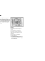
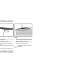
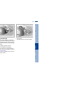
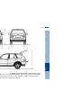
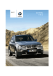
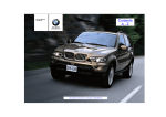
X5 3.0i
X5 4.4i
X5 4.6is
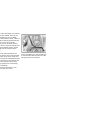
ations, and thank you for choosing a BMW.
familiarity with your vehicle will provide you with enhanced control and
when you drive it. We therefore have this request:
ke the time to read this Owner's Manual and familiarize yourself with the
n that we have compiled for you before starting off in your new vehicle. It
mportant data and instructions intended to assist you in gaining maximum
atisfaction from the unique range of technical features on your BMW. The
so contains information on vehicle maintenance designed to enhance
safety and contribute to maintaining the value of your BMW throughout an
service life.
onal information refer to the supplemental manuals.
er's Manual should be considered a permanent part of this vehicle. It
ay with the vehicle when sold to provide the next owner with important
safety and maintenance information.
ual is supplemented by a Service and Warranty Information Booklet
ls) or a Warranty and Service Guide Booklet (Canadian models).
mmend that you read this publication thoroughly.
W is covered by the following warranties:
hicle Limited Warranty
Rust Perforation Warranty
Emissions System Defect Warranty
Emissions Performance Warranty
a Emission Control System Limited Warranty
nformation about these warranties is listed in the Service and Warranty
n Booklet (US models) or in the Warranty and Service Guide Booklet
models).
you an enjoyable driving experience.
Vorwort
cks and security systems:
ys 30
ntral locking system 30
ening and closing
via the door lock 31
ening and closing
via the remote control 32
ening and closing
from the inside 35
gate 36
lgate 37
rm system 39
ctric power windows 40
ding/tilt sunroof with glass
moonroof 42
justments:
rrect sitting posture 44
ats 44
chanical seat 45
wer seat 46
ad restraints 47
wer rear-seat backrest
djustment 48
ety belt 49
at, mirror and steering wheel
memory 50
at heating 51
usting steering wheel 52
ering wheel heating 53
rors 53
Passenger safety systems:
Airbags 55
Transporting children safely 58
Vehicle Memory, Key
Memory 61
Driving:
Ignition lock 62
Starting the engine 62
Switching off the engine 64
Parking brake 64
Manual transmission 65
Automatic transmission with
Steptronic 66
Indicator/Headlamp flasher 68
Washer/Wiper system/Rain
sensor 69
Cruise control 71
Everything under control:
Odometer, outside temperature
display 74
Tachometer 75
Energy control 75
Fuel gauge 75
Coolant temperature gauge 76
Service Interval Display 76
Check Control 77
Computer 80
Multi-Information Display
(MID) 82
Digital clock in the MID 83
Computer in the MID 86
Inhalt
Overview
Maintenance Controls
Repairs
Wheels and tires:
Tire inflation pressures 136
Tire condition 136
Tire replacement 137
Wheel and tire
combinations 139
Winter tires 140
Snow chains 140
Data
Special operating instructions:
Break-in procedures 132
Driving your BMW X5 133
General driving notes 134
Antilock Brake System
(ABS) 134
Brake system 135
Index
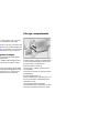
oading and transporting:
ki bag 120
Cargo area
Fold the rear backrests
down 122
Cargo area cover 122
Partition net 123
Cover panels in the cargo
area 124
Power outlets 125
Pull-out cargo floor 126
towing cargo 127
Roof-mounted luggage rack 128
Operation, maintenance
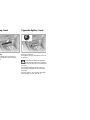
Cabin convenience:
BMW Universal Transmitter 113
Glove compartment 116
torage compartments 116
Cellular phone 117
Beverage holder 117
Glasses compartment 118
Ashtray, front 118
Cigarette lighter, front 118
Ashtray, rear 119
Cigarette lighter, rear 119
5n
sistance, giving and
eiving:
mp-starting 164
wing the vehicle 166
Technical data
placement procedures:
board tool kit 152
ndshield wiper blades 152
mps and bulbs 153
anging a wheel 156
tery 162
ses 163
Engine specifications 170
Dimensions 171
Weights 172
Capacities 173
Index
Data
Repairs
Maintenance Controls
Overview
7n
ls used
dicates precautions that must
followed precisely in order to
e possibility of personal injury
ous damage to the vehicle.<
ontains information that will
sist you in gaining the optimum
from your vehicle and enable
are more effectively for your
<
fers to measures that can
taken to help protect the
ment.<
t Identifies index entries that refer to
owner service procedures or topics on
vehicle maintenance.
Identifies systems or components,
which can either be activated or
adapted to suit an individual driver's
requirements ("Vehicle Memory", "Key
Memory"), refer to page 61.
Remember that activation and adjustments on some of these systems can
only be performed at your BMW Sports
Activity Vehicle center.<
s the end of a specific item of
tion.
ates special equipment, countryequipment and optional extras.
Notes
Symbols
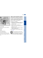
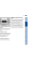
The individual vehicle
If your BMW features equipment which
is not described in this Owner's Manual
(car radio or telephone, for instance),
Supplementary Owner's Manuals are
enclosed. We ask you to read these
manuals as well.
Controls
We hope you will understand that
equipment and features are included
that you might not have chosen for your
vehicle. Any differences can easily be
identified, since all optional accessories
and special equipment are marked with
an asterisk *.
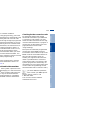
Maintenance
BMW pursues a policy of continuous,
ongoing development that is conceived
to ensure that our vehicles continue to
embody the highest quality and safety
standards combined with advanced,
state-of-the-art technology. For this
reason, it is possible that the features
described in this Owner's Manual could
differ from those on your vehicle. Nor
can errors and omissions be entirely
ruled out. You are therefore asked to
appreciate that no legal claims can be
entertained on the basis of the data,
illustrations or descriptions in this
manual.
Repairs
On buying your BMW, you have
decided in favor of a model with individualized equipment and features. This
Owner's Manual describes all models
and equipment that BMW offers within
the same group.
Data
Status at time of printing
Index
The individual vehicle
Overview
9n
Aktualität bei Drucklegung
portant safety information.
Installation and operation of non-BMW
approved accessories such as alarms,
r own safety, use genuine parts radios, amplifiers, radar detectors,
wheels, suspension components, brake
essories approved by BMW.
dust shields, telephones (including
ou purchase accessories tested
operation of any portable cellular phone
proved by BMW and Original
from within the vehicle without using an
arts, you simultaneously acquire
externally mounted antenna) or transurance that they have been thorceiver equipment (for instance, CBs,
ested by BMW to ensure
walkie-talkie, ham radio or similar
m performance when installed
accessories) may cause extensive
vehicle.
damage to the vehicle, compromise its
arrants these parts to be free
safety, interfere with the vehicle's elecfects in material and workman- trical system or affect the validity of the
BMW Limited Warranty. Contact your
BMW Sports Activity Vehicle center for
ill not accept any liability for
additional information.<
resulting from installation of
d accessories not approved by
Maintenance, replacement, or
repair of the emission control
annot test every product from
devices and systems may be performed
anufacturers to verify if it can be
by any automotive repair establishment
a BMW safely and without risk
or individual using any certified autor the vehicle, its operation, or its
motive part.<
nts.
BMW Parts, BMW Accessories
er products approved by BMW,
r with professional advice on
ese items, are available from all
ports Activity Vehicle centers.
Symbol on vehicle parts
Indicates that you should consult
the relevant section of this
Owner's Manual for information on a
particular part or assembly.
For your own safety
Overview
11n
To contact NHTSA, you may either call the Auto Safety Hotline toll-free at 1-800-424-9393 (or 366-0123 in
Washington, D.C. area) or write to: NHTSA, U.S. Department of Transportation, Washington, D.C. 20590. You can
also obtain other information about motor vehicle safety from the Hotline.
Maintenance
Repairs
If NHTSA receives similar complaints, it may open an investigation, and if it finds that a safety defect exists in a
group of vehicles, it may order a recall and remedy campaign. However, NHTSA cannot become involved in individual problems between you, your dealer or BMW of North America, LLC.
Data
If you believe that your vehicle has a defect which could cause a crash or could cause injury or death, you should
immediately inform the National Highway Traffic Safety Administration (NHTSA) in addition to notifying BMW of
North America, LLC, P.O. Box 1227, Westwood, New Jersey 07675-1227, Telephone (201) 307-4000.
Index
REPORTING SAFETY DEFECTS
Controls
The following only applies to vehicles owned and operated in the US.
13n
Overview
Overview
Operation, maintenance
Maintenance
Controls
Controls and features
Repairs
Owner service procedures
Data
Technical data
Index
Index
Overview
/Washer system 69
7 Hazard warning flashers
window defroster 104, 109
8 Horn, the entire surface
al locking system 30
9 Adjusting steering wheel 52
ector lever and program display
automatic transmission* 66
vice Interval Display 76
Overview
Maintenance Controls
Repairs
Data
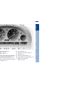
cator and warning
ps 18 to 21
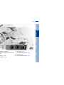
10 Computer display –
operation via the turn signal lever,
refer to page 80:
> Outside temperature
> Average fuel consumption
> Cruising range
> Average speed
Index
olant temperature gauge 76
15n
meter and trip odometer 74
cator for Check Control 77
15 Reset button for trip odometer 74
16 Indicator and warning
lamps 18 to 21
Repairs
Maintenance Controls
Overview
17n
dicator and warning
mps 18 to 21
12 Trip odometer 74
HECK button 77
14 Odometer 74
elector lever and program display
r automatic transmission* 66
15 Service Interval Display 76
dicator lamp for Dynamic Stability
ontrol (DSC) 20
Data
16 Reset button for trip odometer 74
17 Indicator and warning
lamps 18 to 21
Index
utside temperature display 74
13 Indicator for Check Control 77
top immediately
Battery charge current ●
The battery is no longer being
charged. There is a malfunction
ternator drive belt or in the
g circuit of the alternator. Please
the nearest BMW Sports
Vehicle center.
he drive belt is defective, do not
ntinue driving. The engine could
aged due to overheating. If the
lt is defective, increased
effort is also required. <
Engine oil pressure ●
Stop the vehicle immediately
and switch off the engine.
he engine oil level; top off as
d. If the oil level is correct:
contact the nearest BMW Sports
Vehicle center.
o not continue driving. The
gine could be damaged
e of inadequate lubrication. <
Parking brake*/
Brake hydraulic system ●
Comes on when you engage the
parking brake. For additional information: refer to page 64.
Comes on although the parking brake
is released: have the brake fluid level
checked. Before continuing your
journey, be sure to read the notes on
pages 135 and 146.
Also comes on in the Check Control
with the message "CHECK BRAKE
LININGS".
Parking brake warning lamp*/
Brake hydraulic system warning
lamp for Canadian models.
Tire Pressure Monitor (RDC) * ●
In addition, an acoustic signal is
sounded: a flat tire has
occurred. Reduce vehicle speed immediately and stop the vehicle. Avoid hard
brake applications. As you steer the
vehicle, use caution and avoid overcorrecting.
For additional information: refer to
page 98
19n
Airbags ●
Please have the system
inspected by your BMW Sports
ty Vehicle center.
dditional information: refer to
55.
ABS warning lamp for Canadian
models.
Engine oil level
Comes on while driving:
The oil level is at the absolute
minimum; refill as soon as possible. Do
not drive more than approx. 30 miles
(50 km) until you do.
For additional information: refer to
page 143.
Engine oil level
Comes on after the engine has
been switched off: add engine
oil at your earliest opportunity (when
you stop to refuel).
For additional information: refer to
page 143.
Overview
Maintenance Controls
Please fasten safety belts ●
Together with an acoustic signal
or a message* in the Check
ol. Comes on until the safety belts
stened. For additional information
ety belts: refer to page 49.
Repairs
Parking brake warning lamp* for
Canadian models.
Antilock Brake System (ABS) ●
ABS has been deactivated in
response to system malfunction.
Conventional braking performance
remains available with no loss of efficiency. Please have the system
inspected by your BMW Sports Activity
Vehicle center.
For additional information: refer to
page 134
Data
Parking brake*
Comes on when the parking
brake is engaged.
dditional information: refer to
64.
Yellow: check as soon as possible
Index
an important reminder
Dynamic Stability Control
DSC) ●
ndicator lamp flashes:
tem is active and governs drive
king force.
ning lamp comes on and stays
e driving:
s been switched off with the
If, after repeatedly pressing the
tton, the warning lamp still does
off, then that means that the
DC and the vehicle's roadability are defective.
have the system checked by the
BMW Sports Activity Vehicle
itional information: refer to
2 and 94.
Engine electronics*
There is a fault in the engine's
electronic control system. You
tinue to drive with reduced
output or engine speed. Please
e system inspected by your
ports Activity Vehicle center.
Tire Pressure Monitor (RDC)* ●
Check tire inflation pressures,
efer to pages 26, 98
Service Engine Soon ●
If the indicator lamp comes on
either continuously or intermittently, this indicates a fault in the
emissions-related electronic systems.
Although the vehicle remains operational, you should have the systems
checked by your BMW Sports Activity
Vehicle center at the earliest possible
opportunity.
For additional information: refer to
page 149.
Service Engine Soon warning
lamp for Canadian models.
Check Filler Cap* ●
If the indicator lamp comes on
although the fuel cap is secured
correctly: this indicates a malfunction in
the fuel system. Have the system
inspected by your BMW Sports Activity
Vehicle center at the earliest opportunity.
Additional information: refer to page 25
21n
Maintenance Controls
Repairs
Data
Index
High beams
Lights up when the high beams
are on or the headlamp flasher
uated.
dditional information: refer to
68 and 101.
Overview
for your information
on buttons
between phone and radio,
e and CD.
Volume
Cruise control: calling up.
d:
briefly: scans for stations in FM
ded pressure: search function
briefly: jump to next track
ded pressure: fast forward in
ette
briefly: stop track scan or fast
rd
ded pressure: fast forward
e
personal phone book.
: functions as for fast forward.
Cruise control: store and accelerate (+);
decelerate and store (–).
Cruise control: activate/interrupt/deactivate.
Recirculated-air mode and automatic
recirculated-air control (AUC) or heated
steering wheel: switch on/off.
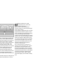
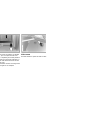
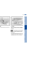
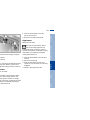
rst-aid kit is located under the
passenger's seat.
en: pull the handle and fold the
down.
Overview
23n
Maintenance Controls
t-aid kit*
Data
Index
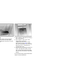
Some of the articles in the first-aid
kit may be used within a limited
only. For this reason, check the
tion dates of each of the items
arly, and replace any whose
tion dates have passed. You can
re replacements in any drugstore
armacy.
s observe all legal regulations
ing a first-aid kit to be carried in
hicle.<
Repairs
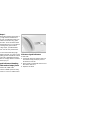
ose: fold the cover up.
530us008
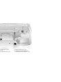
hen handling fuels, comply with
of the applicable safety precaud regulations pertaining to
ever carry spare fuel containers
vehicle. Whether empty or full,
ontainers can leak, cause an
on, or lead to fire in the event of
on.<
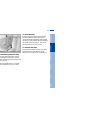
Simple and environmentally
friendly
Open the filler cap carefully to
prevent fuel from spraying out.
Fuel spray may cause injury.
Do not top off. Topping off may cause
fuel spillage.<
Keep the filler cap in the bracket
attached to the fuel filler door.
When refueling, insert the filler nozzle
completely into the filler pipe. Pulling
the nozzle out of the pipe during refueling
> results in premature pump shutoff
> and will reduce the effect of the vapor
recovery system on the pump.
l specifications
25n
red fuel:
mium Unleaded Gasoline,
. 91 AKI.
Overview
ngine uses lead-free gasoline
Repairs
Data
Index
Do not use leaded fuels. The use
of leaded fuels will cause permadamage to the system's oxygen
r and the catalytic converter.<
Maintenance Controls
Anti Knock Index
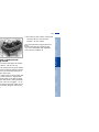
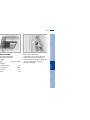
heck tire inflation pressures
gularly — at least every two
and before beginning a longer
orrect tire pressure can otherd to tire damage and accidents.
he tire inflation pressure of the
re. Inflate the spare tire to
est inflation of any tire on your
<
Comply with tire approval
specifications
The inflation pressures in the table
apply to tire sizes and tires from BMWapproved manufacturers. Your
BMW Sports Activity Vehicle center is
familiar with these pressures. Higher
pressures may be specified for tires
from other manufacturers.
Your vehicle is equipped with tires that
not only meet US standards, but also
European standards. We recommend
the exclusive use of BMW-approved
tires.
Maintenance Controls
39 (270)
Repairs
32 (220)
Data
32 (220)
Index
20)
Overview
27n
Controls
29n
Overview
Overview
Operation, maintenance
Maintenance Controls
Controls and features
Repairs
Owner service procedures
Data
Technical data
Index
Index
key for storage in a safe place,
as in your wallet. This key is not
ded for continuous use
and ignition key
ock for the glove compartment
ot be operated with this key.
s recommended for valet
ng, for instance.
Central locking system
The concept
The central locking system is ready for
operation as soon as you close the front
doors. The system engages and
releases the locks on the
> doors
> liftgate/tailgate
> fuel filler door.
The central locking system can be
operated
> from outside via the driver's door lock
as well as via the remote control
> from inside via the button for the
central locking system.
If the system is locked from inside, the
fuel filler door remains unlocked, refer
to page 35.
When the system is actuated from
outside of the vehicle, the anti-theft
system is actuated simultaneously. The
alarm system is also armed or
disarmed.
In the event of an accident, the central
locking system unlocks automatically
(only those doors which were not
locked separately with the safety lock
buttons), refer to page 35. In addition,
the hazard warning flashers and interior
lamps come on.
door lock
31n
open: with the door closed, turn
key to the "Unlock" position and
d it
close: with the door closed, turn
key to the "Lock" position and
d it.
Watch during the closing process
o be sure that no one is inadvertnjured. Releasing the key stops
peration.<
ual operation
Maintenance Controls
an also operate the windows and
g/tilt sunroof via the door lock.
Overview
enience operation
Index
Data
Repairs
event of an electrical malfunction)
he key to the extreme left or right
ock/lock the door.
mote control
Master keys with remote control
unit
Children might be able to lock the
doors from the inside. For this
reason, always take the vehicle's keys
with you so that the vehicle can be
opened again from the outside at any
time.<
Master keys that are used repeatedly are always ready for operation since the battery in the key is
charged automatically in the ignition
k, convenience opening and
lock as you drive.
system
If it is no longer possible to lock the
and secure, interior lamp activa- vehicle via the remote control, the
switching off tilt alarm sensor
battery is discharged. Use this key
nterior motion sensor
while driving for an extended period in
the liftgate, panic mode
order to charge the battery, refer also to
page 30.
To prevent unauthorized use of the
remote control, surrender only the door
and ignition key 3 or the spare key 2
(refer to page 30) when leaving the
vehicle for valet parking, for example.
In the event of a system malfunction,
please contact your BMW Sports
Activity Vehicle center. You can also
obtain replacement keys there.<
emote control
To open the liftgate
button.
Press button.
Before and after a trip, be sure
that the tailgate/liftgate was not
opened unintentionally.<
ocking the vehicle, press button
To switch off the alarm
Press button.
Repairs
button a second time immediafter locking.
dditional information: refer to
40.
By pressing and holding the button for
more than two seconds, you can trigger
an alarm via the alarm system if there is
an impending danger (the alarm system
must be armed).
Data
witch off the tilt sensor alarm
nterior motion sensor
Panic mode
Index
witch on the interior lamps
Maintenance Controls
ck and secure
Overview
33n
mote control
owners only
nsmitter and receiver units
with part 15 of the FCC (Federal
nication Commission) regulaperation is governed by the
g:
LX8EWS
LX8FZVS
LX8FZVE
ance statement:
vice complies with part 15 of the
les. Operation is subject to the
g two conditions:
device may not cause harmful
erence, and
evice must accept any interferreceived, including interference
may cause undesired operation.
y unauthorized modifications or
anges to these devices could
user's authority to operate this
ent.<
e inside
the release handle for each door
ce: the first pull unlocks the door,
the second one opens it.
When the vehicle is moving, do
not lock the doors with the safety
lock buttons. Doors locked in this
manner would not unlock automatically
in the event of an accident.
Since passengers or animals remaining
in the vehicle might be able to lock the
doors from the inside, take the vehicle's
keys with you so that the vehicle can be
opened again from the outside at any
time.<
Maintenance Controls
> Use the central locking button to lock
all of the doors simultaneously,
or
> press down the individual safety lock
buttons. The fuel filler door remains
unlocked. As an added design
feature to prevent the driver from
being inadvertently locked out of the
vehicle, the driver's safety lock
button will not engage as long as the
door is open.
Repairs
er unlock the doors together with
button for the central locking
tem and then pull the door handle
ve the armrest
Data
To engage the locks
Index
nlock and open the doors
Overview
35n
530de316
ng from inside the vehicle
Manual release
his button to open the liftgate
e vehicle is stationary.
In the event of an electrical malfunction,
you can release the liftgate manually:
pointed or sharp-edged objects
uld strike the rear window while
be sure to provide protection
all edges. If you do not do this,
ting conductors of the rear
could be damaged.<
rmation on the cargo area cover
other details in the cargo area,
"Cargo area", beginning on
22.
1. Remove the plastic plug from inside
the cargo area and pull toward the
interior (arrow). The liftgate will be
released
2. Reinstall the plug.
Repairs
When opened, the tailgate can
accept loads of up to 440 lbs
(200 kg). When the vehicle is parked,
you may utilize the tailgate as a seat or
as a loading platform for luggage or
recreation gear, for example.<
Data
Press the button:
You can fold the tailgate down.
Index
To open
Maintenance Controls
Overview
37n
530de246
Operate the vehicle only when
both gates are completely closed.
wise, exhaust fumes could penehe interior of the vehicle. Should it
solutely necessary to operate the
e with an open gate:
se all windows. Shut the sliding/
sunroof
ease the air supply for the air
ditioner or automatic climate
trol to a high level, refer to
e 104 or 108.<
Tailgate
g the same tool, press the latch
direction of the arrow; the
te is released
stall the trim panel.
394de302
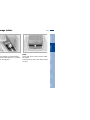
Luggage straps
Use the retaining straps on the cargo
area floor to secure smaller items of
luggage.
Movement is reduced when objects are
placed on the straps.
The lashing eyes located at the corners
of the cargo area provide you with a
convenient means of attaching luggage
nets* or flexible straps for securing
luggage.
Refer also to "Stowing cargo" on
page 127.
39n
Repairs
> The indicator lamp below the interior
rearview mirror flashes continuously:
the system is armed
> The indicator lamp flashes during
arming: the door(s), the hood or liftgate are not completely closed. Even
if you do not close the alerted area,
the system begins to monitor the
remaining areas, and the indicator
lamp flashes continuously after
10 seconds. However, the interior
motion sensor is not activated
> If the indicator lamp goes out when
the system is disarmed: no manipulation or attempted intrusions have
been detected in the period since the
system was armed
Data
an still open the liftgate after the
m has been armed by pressing the
n of the remote control, refer to
33. When you close the liftgate, it
ured again.
Indicator lamp displays
Index
You can have different acknowledgment signals set to confirm
m arming and disarming.<
530us018
the vehicle is locked or unlocked
he key or the remote control, the
system is also simultaneously
d or disarmed.
Maintenance Controls
Overview
m and disarm the alarm
m
Electric power windows
r motion sensor
r, be sure to switch off the inteion sensor (see the previous
when you
children or animals in the
e
d to leave the windows or
g/tilt sunroof open.
530us020
for the interior motion sensor to
properly, the windows and
ilt sunroof must be completely
Open and close windows
From ignition key position 1:
> Press the switch up to the pressure
point:
The window continues to move as
long as you continue to hold the
switch
> Press the switch beyond the pressure
point:
The window moves downward automatically. Touch the switch again to
stop the opening movement.
You can close the windows in the same
manner by pulling the switch.
Maintenance Controls
Overview
Press the safety switch whenever
children are riding in the rear of
the vehicle. Careless use of the power
windows can lead to injury.<
Repairs
With the safety switch, you can prevent
the rear windows from being opened or
closed via the switches in the rear
passenger area (by children, for
example). You can also prevent adjustments of the power rear-seat backrests
from the rear passenger area, refer to
page 48.
Data
Safety switch
Index
530us209
Despite this safety feature, be
extremely careful that the closing
of the window is not obstructed
ever it is closed. Otherwise, an
t might not touch the contact strip
me situations (with very thin
ts, for instance).
an override this safety feature by
g the switch beyond the pressure
and holding it.
use the power windows are sealed
h pressure to prevent wind noise
closed, a powerful motor is
ed for efficient closing. When
g the windows, always ensure
hey are not obstructed in any way.
pervised use of these systems can
in serious personal injury.
ve the ignition key to deactivate
ectric power windows whenever
ave the vehicle. Never leave the
n the vehicle with unsupervised
en. Never place anything that
obstruct the driver's vision on or
o the windows.<
41n
oonroof*
– Opening – Closing
e ignition key in position 1 or
press the switch or slide it in the
direction until you feel resis-
dliner slides back somewhat
ou raise the sunroof. When the
is opened the headliner retracts
t remains open, and it is possible
it back and forth as long as the
is not completely open.
e headliner insert cannot be
osed with the sliding/tilt sunroof
sed position.<
e ignition has been switched off,
still operate the sliding/tilt
as long as neither of the front
as been opened.
Automatic* opening and closing
Press the switch briefly past the pressure point and then release it.
Other automatic operations are:
> With the sunroof open, press the
switch briefly toward "Lift": the
sunroof automatically extends to its
fully raised position.
Pressing the switch again briefly stops
the motion.
> With the sunroof raised, hold the
switch toward "Open" until the roof
has reached the desired position.
Safety feature
If the sliding/tilt sunroof encounters
resistance at a point roughly past the
middle of its travel when it is closing,
the closing cycle is interrupted and the
sliding/tilt sunroof will open again
slightly.
moonroof*
In the event of an electrical malfunction,
you can operate the sliding/tilt sunroof
manually:
se the sliding/tilt sunroof fully
ss and hold the switch for approx.
enty seconds.
1. Open the glasses compartment, refer
to page 118
2. Insert the Allen wrench from the
vehicle tool kit (refer to page 152) in
the opening provided and turn the
sliding/tilt sunroof in the desired
direction.
Maintenance Controls
nterruptions in the electrical
y (when the battery is discond, for instance), the sunroof may
ft. To reinitialize the mechanism:
Repairs
Manual operation
Data
er loss
Index
530us124
Overview
43n
ith safety belts
ever allow more than one person
wear a single safety belt. Never
fants or small children to ride in
nger's lap. Avoid twisting the
le routing it firmly across the
nd shoulder, wear it as snugly
your body as possible. Do not
e belt to rest against hard or
bjects in your pockets. Never
e belt across your neck, do not
ross sharp edges and ensure
belt does not become caught
ed. Avoid wearing bulky
and pull on the lap belt periodiretension it over your shoulders.
vent of a frontal impact, a loose
could slide over your hips,
to abdominal injury. In addition,
ty belt's restraint effectiveness
ed if the belt is worn loosely.
nt mothers should always wear
ety belts, taking care to position
belt against the lower hips,
will not exert pressure against
ominal area.<
ructions on operating the safety
fer to page 49.
Seats
Observe the following before
adjusting
Never try to adjust your seat while
operating the vehicle. The seat
could respond with unexpected movement, and the ensuing loss of vehicle
control could lead to an accident. Never
ride with the backrest reclined to an
extreme horizontal angle (especially
important for front passengers to
remember). Keep the backrest relatively
upright to minimize the risk of "sliding
under" the safety belt and sustaining
injury in an accident.<
Seat adjustment
> Mechanical seat adjustment, refer to
page 45
> Power seat adjustment, refer to
page 46
> Head restraints, refer to page 47
> Power rear backrest adjustment,
refer to page 48
Overview
Maintenance Controls
Pull the lever and adjust the position of
the thigh support for your personal
comfort.
Repairs
530de253
You can adjust the thigh support additionally:
Data
Comply with the adjustment
nstructions on page 44. Failure
so could result in diminished
nal safety.<
Adjusting the BMW sports seat*
Index
krest angle
the lever and apply weight to or
ove weight from the backrest as
uired.
45n
> Press the front/rear of the switch:
Increase/decrease curvature
> Press the upper/lower end of the
switch:
Increase the upper/lower curvature.
ng the BMW comfort seat*
at allows you to make additional
ents for:
ar support
der support
restraint height
support:
n adjust the backrest's contour
tional support in the curvature
spine's lumbar region.
per hips and spinal column
supplementary support to help
ntain a relaxed, upright posture.
Head restraints
47n
To adjust the height of the front or rear
head restraints, pull the head restraint
up or push it down.
Power electric height adjustment, refer
to page 46.
Head restraints reduce the risk of
spinal injury in the event of an
accident. Adjust the head restraint so
that its center is approximately level
with your ears.<
Maintenance Controls
Repairs
the switch in the desired direc-
To adjust the angle of the front head
restraints, tilt the head restraint to the
desired angle.
Data
restraint height:
Adjustments
Index
Make corrections in the forward/
backward adjustment of the seat
sure that the safety belt still fits
against your body. If you do not
s, the protection provided by the
belt may be reduced.<
530de250
ust the upper backrest section to
extreme rear position
the backrest down to a slightly
re horizontal angle
ng the upper backrest section
ward until your shoulders are well
pported.
Overview
passenger's seat adjusted for
d traveling:
n make separate adjustments of
krest tilt angle on the right and
s.
n select a comfortable sitting
and also increase the capacity
argo area by moving the backo their most upright position.
e rear seats: press the correg switch.
u can prevent adjustments of
e power rear-seat backrest from
passenger area with the safety
or the power windows, refer to
1.<
530de224
er rear-seat backrest adjustment*
From the cargo area: the switches are
located on both sides of the cargo area.
49n
Safety belt height adjustment
You can adjust the safety belts to fit
your own physical dimensions by using
the safety belt height adjustment.
Maintenance Controls
530de259
Overview
n the rear, the belt buckle with
he word "CENTER" is intended
sively for passengers sitting in the
e. If it is not possible to extract the
r belt, this indicates that the larger
est is not securely locked, refer to
122.<
Data
If the safety belt system has been
subjected to the stresses involved
in an accident or otherwise damaged:
Have the entire safety belt system
replaced by your BMW Sports Activity
Vehicle center. In addition, have your
BMW Sports Activity Vehicle center
inspect the safety belt anchors. Otherwise, the safety function can no longer
be ensured.c
Index
Also observe the instructions on
adjusting the seats on page 44.
Repairs
Slide the button up or down as
required.
memory*
re
To call up a stored setting
he ignition key to position 1 or 2 Convenience function:
st the desired positions for the
1. Open the driver's door after
exterior mirror and steering
unlocking the vehicle or place the
l
ignition key in position 1
s the MEMORY button: the indi- 2. Briefly press memory button 1, 2
lamp in the button comes on
or 3, as desired.
s memory button 1, 2 or 3, as
Movement stops immediately when
ed: the indicator lamp goes out.
one of the seat-adjustment or
memory buttons is activated during
the adjustment process.
Security function:
1. With the driver's door closed and the
ignition key either removed or in
position 0 or 2
2. Maintain pressure on the desired
memory button (1, 2 or 3) until the
adjustment process is completed.
If you press the MEMORY button accidentally: press the button a second
time — the indicator lamp goes out.
Do not call up a position from the
memory while the vehicle is
moving. There is a risk of accident from
unexpected movement of the seat or
steering wheel.<
Seat heating*
enger side exterior mirror tilt
ion
Front
an deactivate this automatic
e by setting the mirror selector
h to the "passenger side" position.
Maintenance Controls
530de233
You can also switch the higher heating
modes off directly:
Press the button and hold it slightly
longer.
Repairs
You can call up different heating modes
by repeatedly pressing the button.
Data
ve the mirror selector switch
ow) to the "driver's mirror" posin
en the gearshift lever or the
ector lever is placed in "Reverse",
passenger-side mirror tilts downrd to help the driver monitor the
a directly adjacent to the vehicle
ing parking (curbs, etc.).
The seat cushion and backrest can be
heated when the ignition key is in position 2.
Index
matic curb monitor)
51n
Overview
l memory*
sting steering wheel
ering wheel can be moved in
our directions. Adjust the wheel
ng the control lever in the
direction.
o not adjust the steering wheel
hile the vehicle is moving. If you
here is a risk of accident from
cted movement.<
e the steering wheel setting,
"Seat, mirror and steering
memory" on page 50.
Automatic steering wheel
adjustment
(only in conjunction with seat, mirror
and steering wheel memory)
In order to make it easier to get into and
out of the vehicle, the steering wheel
automatically moves into the top position and returns to the driving (memory)
position.
This automatic feature is controlled by
the position of the ignition key and by
the driver's door.
rors
/right selector switch
Before going through a car wash,
manually fold the exterior mirrors
d, otherwise they could be
ged, depending on the width of
ar wash system.<
The passenger-side mirror
features a convex lens. When estimating the distance between yourself
and other traffic, bear in mind that the
objects reflected in the mirror are closer
than they appear. This means that estimations of the distance to following
traffic should not be regarded as
precise.<
Self-defrosting mirrors
Both mirrors are defrosted automatically when the ignition key is in
position 2.
Overview
Convex mirror
Maintenance Controls
ror switch for 4-way adjustment
To store the mirror settings, refer to
"Seat, mirror and steering wheel
memory" on page 50.
Repairs
ior mirrors
53n
sting manually
Index
on the outer edges of their
s.
Data
an also adjust the mirrors manu-
r and exterior rearview
with automatic dimmer*
mirrors automatically dim
an infinitely-variable range.
tomatically revert to their
ed mode whenever the transis placed in reverse gear or
lever in "Reverse".
re two photocells located in the
rearview mirror for this purpose.
otocell (arrow) is in the mirror
while the other is offset somethe back of the mirror.
For trouble-free operation, keep the
photocells clean and do not cover the
area between the interior rearview
mirror and the windshield. Do not
attach any kind of stickers on the windshield in front of the mirror, either.
The airbags will not be triggered in
he event of a minor accident, a
e roll-over, or collisions from the
<
Overview
Maintenance Controls
Repairs
formation on the correct sitting
re, refer to page 44.
Data
The side airbags in the rear
passenger area* of your vehicle
lready have been deactivated
at the time of manufacture or by a
Sports Activity Vehicle center.
may have them activated if you
e to do so. Please contact your
Sports Activity Vehicle center for
onal information.<
Do not apply adhesive materials to
the cover panels of the airbags,
cover them or modify them in any other
way. Do not attempt to remove the
airbag restraint system from the
vehicle. In the event of a malfunction,
deactivation, or triggered actuation (as
a response to an accident) of the airbag
restraint system, consult your
BMW Sports Activity Vehicle center for
testing, repairs or service operations.
Do not modify or tamper with either the
wiring or the individual components in
the airbag system. These include the
padded steering wheel hub, the instrument cluster, the side trim panels of the
front or rear doors and the roof pillars or
the sides of the headliner. Do not
remove or dismantle the steering wheel
yourself. To ensure compliance with
official safety regulations, entrust
disposal of airbag generators to a
BMW Sports Activity Vehicle center.
Unprofessional attempts to service the
system could lead to failure in an emergency or undesired airbag activation,
either of which could result in personal
injury. Do not touch the individual
components directly after the system
has been triggered, as otherwise there
is a danger of burns.<
Index
mpact. Each of the side airbags is
ned to help support the upper
55n
hen all these guidelines are
d, there is still a small residual
njuries to the face, hands and
curring from airbag deployment
ed instances. The ignition and
noise may provoke a mild
ary hearing loss in extremely
e individuals.
warning information is also
d on both sun visors.
530us026
r seat side airbags may already
en deactivated, either at the
manufacture or by a BMW
Activity Vehicle center. Labels in
door opening should indicate
us of your rear seat side
If you are uncertain of their
or wish to have the airbags actir deactivated, please contact
MW Sports Activity Vehicle
<
This is the right way a child should sit in
a child-restraint device when rear side
airbags (arrow) are provided.
57n
The indicator lamp in the instrument cluster shows the operational status of the airbag
m from ignition key position 1
p.
Overview
ator lamp
e is a system malfunction, have
BMW Sports Activity Vehicle
r inspect the system immediately.
do not, there is a risk that the
gs will not be triggered within their
al response range, even if the level
pact would normally have trigthem.
Repairs
indicator lamp fails to come on
indicator lamp comes on briefly
ore going out and then lighting up
in.
Data
m malfunction:
Index
indicator lamp comes on briefly
n goes out.
Maintenance Controls
m operational:
se a child-restraint system with
strap, three additional tether
ge points (refer to the arrows in
tration) have been provided.
ing on the location selected for
in the rear passenger area,
he tether strap to the correg anchorage point to secure the
straint system. Remove the
st on the middle location.
spective seating position is
th a head restraint lift the head
t and pass the tether strap
n the head restraint and the seat
he tether strap according to the
straint manufacturer's instruc-
Before installing any childrestraint device or child seat,
please read the following:
Never install a rear-facing childrestraint system in the front passenger
seat of this vehicle.
Your vehicle is equipped with an airbag
supplemental restraint system for the
front passenger. Because the backrest
on any rear-facing child-restraint
system (of the kind designed for infants
under 1 year and 20 Ibs/9 kg) would be
within the airbag's deployment range,
you should never mount such a device
in the front passenger seat, since the
impact of the airbag against the child
restraint's backrest could lead to
serious or fatal injuries.
If it is necessary for a child (not an
infant) to ride in the front seat, certain
precautions should be taken. First,
move the passenger seat as far away
from the instrument panel as possible.
This important precaution is intended to
maximize the distance between the
airbag and the child. Older children
should be tightly secured with a safety
belt.
Release the buckle, remove the childrestraint device and allow the belt
retractor to reel the belt completely in.
Overview
Maintenance Controls
To release the belt
Repairs
mation regarding this is located
he buckle latch of each safety
Pull the entire length of the belt from
the belt retractor. Allow the reel to
retract the belt somewhat and engage
the buckle, then tighten the belt against
the child-restraint system. The retraction mechanism is now locked.
Data
the rear belt retractors and the
passenger's safety belt can be
d for mounting and securing childint systems.
To lock the belt
Index
-restraint system security
59n
530de226
stration shows the mounts for a
child-restraint system in the left
t.
Child-safety locks
ll a LATCH child-restraint
please follow the manufacperating instructions and safety
ions.
The door can now be opened from the
outside only.
Slide the safety lever on the rear doors
downward:
61n
ples for Vehicle Memory:
ous signals that can serve as
nowledgment for locking and
ocking the vehicle
activating/activating the "Follow
home" lamps function.
Overview
Maintenance Controls
BMW Sports Activity Vehicle
r can provide you with details on
pabilities of the "Vehicle Memory"
Key Memory" systems. A few
ples follow below:
You will see this symbol
throughout the Owner's Manual. It
is to remind you at appropriate places
of the settings that are available to
you.<
Repairs
the system can do
> Automatically moving the driver's
seat, outside mirror and steering
wheel into position for the respective
person when unlocking the vehicle
> Calling up customized settings for the
automatic climate control when
unlocking the vehicle.
Data
er for you to distinguish between
ent keys, colored decals are
ed together with the keys.
Examples for Key Memory:
Index
your vehicle is unlocked with the
e control, the vehicle recognizes
dividual user by means of a data
nge with the key, and makes
ments accordingly.
ustic warning is sounded when
to remove the ignition key after
the driver's door.
hicles with automatic transssion:
move the selector lever from the
position until the engine is
(ignition key in position 2).
to turn the key to position 0 or
ve it, first move the selector
the "Park" position (Interlock).<
ng lock disengaged
find that it is often easier to turn
ion key from position 0 to posihen you move the steering
lightly to help disengage the
al electrical devices are ready
ation.
g the engine
hicles with manual transmison: depress the clutch when
the engine. If you do not, a lock
s the engine from starting.<
Starting the engine
Before starting
> Engage the parking brake
> Be sure that the gearshift lever is in
"Neutral" (or the selector lever in
"Park" if the vehicle is equipped with
an automatic transmission)
> Depress the clutch pedal.
Do not allow the engine to run in
enclosed spaces. The exhaust
gases contain carbon monoxide, an
odorless and colorless, but highly toxic
gas. Breathing the exhaust gases poses
an extreme health risk, and can lead to
unconsciousness and death.
Do not leave the vehicle unattended
with the engine running. An unattended
vehicle with a running engine represents a potential safety hazard.<
e idle speed is controlled by the
e computer system. Increased
ds at start-up are normal and
d decrease as the engine warms
engine speed does not decrease,
e is required.
vent the battery from discharging,
s switch off electrical devices that
ot in use. Switch the ignition off
the vehicle is not being driven.
Overview
Maintenance Controls
the initial start attempt, allow the
ter to remain engaged somewhat
ger (approx. 10 seconds).
When driving, standing at idle,
and parking the vehicle, take care
to avoid contact between the hot
exhaust system and flammable materials (grass, hay, leaves, etc.). Such
contact could lead to a fire, resulting in
serious personal injury and property
damage.<
Repairs
starts at very low temperatures,
approx. +5 7 (–15 6) and at altiabove 3,300 ft (1,000 meters):
Data
ss the accelerator pedal halfway
wn while engaging the starter.
Extended starting attempts, characterized by excessively frequent
or long periods with the starter
engaged, can lead to damage of the
catalytic converter.<
Index
d the engine fail to start on the
ttempt (if it is very hot or cold, for
ce):
63n
ng brake
king brake is primarily designed
ent the vehicle from rolling while
It operates against the rear
age
er engages automatically when
it up and the "PARK BRAKE" or
E" (in Canada "P") indicator lamp
on in the instrument panel in
key position 2, refer to
8 and 19.
ase
slightly on the lever, press the
and lower the lever.
If, in exceptional circumstances, it
should be necessary to engage
the parking brake while the vehicle is in
motion, do not pull it with excessive
pressure. Keep your thumb pressed
against the release button while carefully pulling up the lever to apply
moderate pressure.
Excessive pressure can lead to overbraking and loss of traction (fishtailing)
at the rear axle.
The brake lamps do not come on when
the parking brake is engaged.
Vehicles with manual transmission:
Always engage the parking brake when
parking on slopes and inclined
surfaces. Even placing the gearshift
lever in 1st gear or reverse may not
provide adequate resistance to rolling.
Vehicles with automatic transmission:
Place the selector lever in "Park".<
To avoid corrosion, apply the parking
brake lightly from time to time when
coasting to a standstill (at a traffic
signal, for instance), provided that it is
safe to do so.
65n
Maintenance Controls
Repairs
Do not hold the vehicle in place on
slopes by slipping or "riding" the
. Use the parking brake instead.
ping clutch increases clutch
<
Data
u do this, the backup lamps will
n automatically when the ignition
in position 2.
Index
t "Reverse" only when the vehicle
mpletely stopped. Press the gearever to the left to overcome the
ance.
Overview
rse
530de263
eptronic*
or lever positions
Range selection
R N D M/S
A detent prevents inadvertent shifts to
the "Reverse" or "Park" selector lever
positions. To disengage the detent,
press the button on the front side of
the selector lever knob (arrow).
nsmission range display varies
ng to the equipment of your
(refer to the illustrations).
g the engine
ine can only be started in
lever positions P ("Park") or
tral").
While the vehicle is stationary and
before shifting out of "Park" or
"Neutral", depress the footbrake in
order to disengage the selector lever's
lock mechanism (Shiftlock).
Hold the footbrake down until starting
off. The vehicle will otherwise "creep"
when a drive position is engaged.<
teptronic*
67n
When you change from D to M/S, the
Sport Program is activated. This is indicated by "D S" in the transmission
range display. The Sport Program is
designed for performance-oriented
driving.
With the first brief touch, the automatic
transmission shifts from the Sport
Program to the manual mode.
Whenever you tap the selector lever in
the "+" direction, the transmission shifts
up, and when you tap it in the "–" direction, the transmission will shift down.
Depending on the equipment version,
1 to 5 or M1 to M5 is indicated in the
transmission range display.
Repairs
M/S Manual mode and
Sport Program
Data
kickdown mode, you achieve
mum acceleration and in
on D top speed.
ss the accelerator pedal past the
ased resistance point at the fulle position.
Index
down
530de264
osition is designed for driving
all normal operating conditions.
ward gears are available.
Maintenance Controls
Overview
Drive
matic shift program)
eptronic*
Indicator/Headlamp flasher
onic transmission control
e
Information on jump-starting, towstarting and towing begins on
page 164.
f the indicator lamp comes on
or the message "TRANS.FAILSAFE PROG" appears in the
Control*, there is a fault in the
ssion system.
e vehicle to a stop. Move the
ssion selector lever to "P". Set
ing brake and switch the engine
ion key to position 0).
ew seconds, then start the
dicator lamp goes out after a
onds, normal transmission
ance has been restored. You
ntinue to drive as usual. If the
r lamp does not go out, you can
e selector lever in all positions.
r, the vehicle will now only drive
with limited gear selection.
appens, avoid extreme engine
nd consult the nearest
ports Activity Vehicle center.
o not work in the engine
mpartment when a drive gear
d or reverse) is engaged. If you
the vehicle could move.<
an the windshield
ecial wash program*
ary dial for control of the wipe
rval or the sensitivity of the rain
sor*
If equipped with a rain sensor *:
1. Switch on the wipers with the lever in
position 1, 2 or 4
2. When the wipers are approx. vertical,
switch the ignition off.
Overview
Maintenance Controls
> With the lever in position 1, switch off
the ignition as soon as the wipers
come to a stop.
For changing the wiper blades, refer to
page 152.
Fold the wipers back down onto
the windshield before you turn the
ignition key to position 1 or 2 again. If
you do not, they could be damaged.<
Repairs
t wipe
ef wipe
The left wiper is partially concealed by
the hood. In order to bring the wipers to
roughly a vertical position (this is important for changing the wiper blades or to
fold the wipers out during frosty
weather, for example):
Data
rmittent mode or rain sensor *
mal wipe
Wipers retracted (home position)
Index
ers retracted
69n
witch the rain sensor off in autoatic car washes. If you do not,
may occur if the wipers switch
entionally.<
l wipe
tem switches automatically to
tent mode when the vehicle is
ing (not on vehicles with rain
).
Clean the headlamps*
> With the special wash program 6
> With every fifth actuation of clean the
windshield 5 when the vehicle's
lighting is switched on.
ers operate at normal speed
e vehicle is not moving (not on
with rain sensor*).
Do not use the washers if there is
any danger that the fluid will
freeze on the windshield. If you do so,
your vision could be obscured. For this
reason, use an antifreeze agent, refer to
page 143.
Do not use the washers when the reservoir is empty. This could cause damage
to the washer pump.<
the windshield
Windshield washer jets
tem sprays washer fluid against
dshield and activates the wipers
ef period.
The windshield washer jets are warmed
automatically when the ignition key is in
position 2.
ipe
l wash program*
there are also several additional
ycles, and the headlamps are
*.
gram is recommended after you
ven on extremely dirty roads.
Overview
You can use cruise control whenever
the system is active while the engine is
running.
Maintenance Controls
hanging the wiper blade, refer to
152.
Repairs
prox. 10 seconds after the lever is
ced in position 0 or
r the engine is switched off.
You can automatically maintain and
store any desired vehicle speed above
approx. 20 mph (30 km/h).
Data
amming is deleted:
71n
Index
ise control*
ntain and store speed or
elerate
utton (+) briefly:
tem maintains and stores the
vehicle speed. Every time you
ouch the button, the speed
es by approx. 0.6 mph (1 km/h).
To decelerate
Press button (–) briefly:
When cruise control is active, every
brief touch of the button reduces the
speed by approx. 0.6 mph (1 km/h).
Press and hold button (–):
With the cruise control active, the
nd hold button (+):
system automatically reduces the
icle accelerates without presthrottle opening to slow the vehicle.
the accelerator pedal. When
When you release the button, the
ase the button, the system
system maintains and stores the
ns and stores the current speed. current speed.
on a downhill gradient, the
gine's braking effect is not suffie controlled speed can be
ed. Speed can drop on uphill
f the engine output is insuffi-
Index
Data
Repairs
Maintenance Controls
Overview
73n
e display
ide temperature display
utside temperature appears in the
y from ignition key position 1 and
r.
an change the units of measure(6/7) by
ssing and holding down the
ton (arrow) with the ignition key
position 1
d then turning the ignition key to 0.
also to page 80.
Ice warning
If the outside temperature drops to
approx. +37.5 7 (+3 6), a signal
sounds as a warning and the display
flashes for a brief period.
The ice warning does not alter the
fact that surface ice can form at
temperatures above +37.5 7 (+3 6),
on bridges or shaded road surfaces, for
instance.<
Fuel gauge
s the current fuel consumption
in liters/100 km on Canadian
). This allows you to see
your current driving style is
ve to fuel economy with
m exhaust emissions.
If the indicator lamp comes on and
stays on, there are approx.
Maintenance Controls
390us006
> 2.0 gal. (8 liter) – 6-cylinder engine
> 2.5 gal. (10 liter) – 8-cylinder engine
Certain operating conditions (such as
those encountered in mountainous
areas) may cause the needle to fluctuate slightly.
Please refuel early, as driving to
the last drop of fuel can result in
damage to the engine and/or catalytic
converter.<
When you switch on the ignition, the
indicator lamp comes on briefly to
confirm that the system is operational.
Data
Tank capacity: refer to page 173.
Repairs
of fuel still in the tank.
Index
he vehicle is stationary, the
goes to "Maximum" (zero on
an models).
75n
Overview
gy control
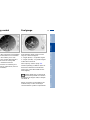
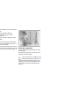
Service Interval Display
een the blue and red zones
390us008
al operating range. It is not
al for the needle to rise as far as
dge of the red zone.
The range of available displays varies
according to your individual vehicle's
equipment.
Green lamps
The number of illuminated lamps
decreases as the time for your next
maintenance visit approaches.
Yellow lamp
This field appears together with
OILSERVICE or INSPECTION.
Maintenance is due. Please contact
your BMW Sports Activity Vehicle
center for an appointment.
Red lamp
The maintenance deadline has been
passed.
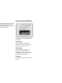
These defects are immediately indicated by a gong and a flashing warning
symbol 1. Simultaneous defects will be
displayed consecutively. These status
messages remain in the display until the
defects are corrected. They cannot be
deleted by pressing the CHECK
button 3:
s messages symbol
ay
CK button
es concerning system faults are
tiated based on two priorities:
> RELEASE PARKINGBRAKE
> COOLANT TEMPERATURE
The coolant is overheated. Stop the
vehicle immediately and switch off
the engine, refer to pages 76 and 145
> STOP!ENGINE OILPRESS
The oil pressure is too low. Stop the
vehicle immediately and switch off
the engine, refer to pages 18 and 143
Repairs
ssages are used to alert the
o system malfunctions when the
key is turned to position 2. The
accompanied by a gong.
Data
Priority 1
Index
numeric display*
Maintenance Controls
Overview
77n
y2
displays appear for 20 seconds
the ignition key is turned to posi. The warning symbols remain
he message disappears. You can
p the messages again for display
essing the CHECK button.
UNKLID OPEN
s message appears only at the
t of a trip
OR OPEN
s message appears after a
imal defined road speed has been
eeded
STEN SEAT BELTS*
ddition to this message, an indior lamp with the safety belt icon
ears and an acoustical signal is
nded
SHER FLUID LOW
fluid level is too low; top off at
next opportunity, refer to
e 143
ECK ENGINE OIL LEV
oil level is at the absolute
imum; refill as soon as possible,
r to page 143. Do not drive more
n approx. 30 miles (50 km) until
add oil
> CHECK FILLER CAP
Check to see whether the fuel filler
cap has been closed properly, refer
to page 24. A fuel filler cap that has
not been closed all the way will set
off the Service Engine Soon lamp
> OUTSIDE TEMP. +23 7 (–5 6)
This display is only an example. The
current temperature is displayed at
outside temperatures of +37.5 7
(+3 6) and below, refer also to
page 74
> SET TIRE PRESSURE*
The RDC has imported the current
inflation pressure in the tires as the
target values which the system will
monitor, refer to page 98
> CHECK TIRE PRESSURE*
Check and correct the tire inflation
pressure to specifications at the
earliest opportunity (next stop to
refuel), refer to page 99
> TIRECONTROL INACTIVE*
A temporary interference of the RDC
or a system fault, refer to page 99
> CHECK BRAKE LIGHTS
A lamp has failed or the electrical
circuit has a fault, refer to pages 155
and 156 or consult a BMW Sports
Activity Vehicle center.
ays after completion of trip
To check the Check Control
he malfunctions registered during
p appear consecutively when the
n key is turned to position 0.
Press the CHECK button 3 with the
ignition key in position 2:
CHECK CONTROL OK appears in the
display.
s messages remain available for a
d of approx. three minutes after
splay goes out and the key is
ved from the ignition lock. Press
HECK button 3. If there were
ple messages, press the CHECK
n repeatedly to view them all in
nce.
You can have the Check Control
and computer messages
displayed in a different language.<
Maintenance Controls
You can find a description of the
computer on pages 80 and 86 as well
as in the Owner's Manual for the
Onboard Computer.
Repairs
isplay appears when you open
iver's door after parking the
e. A supplementary gong is also
.
Computer
Data
HTS ON
Y IN IGNITION LOCK
ECK ENGINE OIL LEV
d engine oil at the next opportunity
xt stop to refuel), refer to
e 143.
No malfunctions are present in the
monitored systems.
Index
ollowing displays will appear when
priate:
Overview
79n
e temperature and average
nsumption
n change the units of measure6/7) for the outside temperaplay by
Cruising range and average speed
The computer bases its calculations
of the cruising range on the previous
driving style and conditions.
The computer ignores any time spent
with the vehicle stationary and the
engine switched off in its average
speed calculations.
To cancel the display
If the button in the turn signal lever is
pressed briefly while the average speed
is displayed, the computer display can
be masked out.
To restart calculations
If you continue to press the button in
ing and holding the trip
the turn signal lever, the average values
meter reset button (in ignition
which were just displayed for fuel
osition 1)
consumption and speed will be recalhen turning the ignition key to 0. culated from that point. The engine
so to page 74.
must be running for this calculation.
Computer with alphanumeric
display*
If your vehicle has Check Control with
alphanumeric display, the system's
computer is described beginning on
page 86 and in the Owner's Manual for
the Onboard Computer.
Index
Data
Repairs
Maintenance Controls
Overview
81n
ion button for audio systems
ion button for the cellular
e*
ator lamp for independent venti-
*
mains on if switch-on time is
ve
hes while operating
ion button for the digital clock
omputer*
ator display for the various
ard systems
6 Display for the entry and query
buttons. Depending on the operating
mode, the functions and alternatives
that can be selected at the buttons
are displayed here
7 Entry and query buttons for operating
the various onboard systems
83n
the left side of the button.
Press the left side of the button.
the right side of the button:
ots flash in the display.
Press.
er the setting:
on the left or right, or hold the
n down.
Press the right side of the button:
The dots and the DATE display flash.
To alter the setting:
Overview
To change the date
Maintenance Controls
hange the time
To store the entry:
Press the right side of the button.
The clock takes leap years into account
and therefore does not have to be reset
manually.
Data
Press on left or right, or hold the button
down.
Index
the right side of the button.
Repairs
ore the entry:
atch
he left side of the button.
shows:
To start the stopwatch function:
Press the right side of the button.
To take an intermediate time reading:
Press.
Press.
The stopwatch display can be seen
counting up; the stopwatch continues
to run.
To halt the stopwatch:
Press the right side of the button.
The stopwatch is halted when the
ignition switch is turned back to 0,
but starts to run again when the ignition
key is turned to 1.<
ter the time:
on the left/right, or hold the
n down.
Directly switching
the independent ventilation*
on and off
The independent ventilation function can only be called up in ignition key position 1.<
Overview
85n
Press the left side of the button.
the right side of the button.
ctivated time is marked with an
sk.
Press.
Maintenance Controls
nfirm the entry:
tivate/deactivate the time:
twice.
Data
the switch-on time is active, the
omes on in the MID. During actual
tion of the ventilation, the LED
s. The LED goes out when the
m is switched off.
Index
an change switch-on times that
already been stored by making a
me entry as described above.
Repairs
witch-on times remain stored until
ntries are made.
limit
Display shows:
imit entry:
n enter the road speed here
h you wish to hear and see a
Enter the limit by pressing the function
er signal: a signal will sound,
buttons.
d LIMIT will flash, and with the
To correct an entry:
Control with alphanumeric
*, the speed limit warning stored
emory will appear on the instruuster briefly.
Press the left side of the button and
ed limit reminder is only
repeat the entry.
d if road speed has fallen at
To store the entry:
mph (approx. 5 km/h) below the
peed limit.
he right side of the button.
he right side of the button.
Press the right side of the button.
87n
emaining distance to the destinaill be displayed on the screen.
the entire distance before starting
urney.
To correct an entry:
Press the left side of the button and
repeat the entry.
Overview
nce to destination
the right side of the button.
Press the right side of the button.
Checking stored value:
the left side of the button.
Press the right side of the button.
Maintenance Controls
To store the entry:
Press the left side of the button.
Repairs
the right side of the button.
ay shows:
Index
Data
an enter the distance by pressing
nction buttons.
ng range
Fuel consumption
ance which the vehicle should
n the remaining fuel in the tank
ayed.
You can have the average fuel
consumption displayed for two different
distances, for example a complete
journey and part of the journey .
he right side of the button.
To start the calculation, select the
CONS function with the engine running.
Press the right side of the button.
play shows the probable range.
hen you have only enough fuel
t to drive fewer than 30 miles
then refuel, as otherwise the
or the catalytic converter could
aged.<
Press on the left or right:
The display will show the average fuel
consumption.
To restart the fuel consumption
calculation:
mputer will only register fuel
s over 1.8 gal (6 liters).
Press on the left or right.
Press the right side of the button.
89n
Press the right side of the button.
Turn the ignition key to position 0.
Deactivate the code:
When you are asked to enter the code
(ignition key in position 1 or 2):
the left side of the button.
ay shows:
the code with the function
ns.
> Enter the code at the function
buttons.
Press the right side of the button.
Maintenance Controls
To store the entry:
lishing and activating the code:
the right side of the button.
Overview
Press on the left side of the button and
repeat the entry.
Repairs
do not have access to the code,
mergency deactivation procedure
ave to be carried out, refer to next
After the code has been entered
correctly and confirmed with the SET
button, the time display appears.
Data
an establish a code that will
nt the engine from being started
s the code is entered.
To correct an entry:
Index
nded immobilizer function
e control
ton on the turn signal indicator
n be used to select the items of
er information which are to
ayed.
his, press:
utton on the lever until PROG 1
s on the display
ID buttons in the order in which
wish the information to be
ayed.
time an entry is stored, the
am number appears on the
ay.
inate the selection procedure:
he right side of the button.
To have all the available information
displayed, press:
> the button on the lever until the
display shows PROG
> the SET button.
To obtain individual items of information, press the button in briefly as often
as necessary.
91n
ual deactivation
the button again.
If there is a malfunction of the system:
The indicator lamp flashes and a short
steady signal tone is sounded
> if you activate PDC with the button
> when you select reverse for the first
time after switching on the ignition
> if a malfunction occurs while the PDC
system is active.
Switch the system off and have the
cause of the malfunction corrected by
your BMW Sports Activity Vehicle
center.
Controls
Maintenance
driving a distance of more than
x. 160 ft (50 m) or exceeding a
d of approx. 20 mph (30 km/h), the
m switches off and the indicator
goes out. Switch the system on
as required.
Repairs
the button; the indicator lamp
s on.
The warning signal is canceled after
approx. 3 seconds if you are moving
parallel to a wall.
Data
ual activation
Index
The distance from an obstacle is indicated in front with a higher intermittent
tone, and at the rear with a lower intermittent tone. As the distance between
vehicle and object decreases, the intervals between the tones become
shorter.
A continuous tone indicates the presence of an object less than approx. 1 ft
(30 cm) away.
Overview
Acoustical signals
mic Stability Control (DSC)
ncept
aintains vehicle stability, even in
driving situations.
tem optimizes vehicle stability
acceleration and when starting
ull stop, as well as optimizing
. In addition, it recognizes
e vehicle conditions, such as
eering or oversteering, and, as
possible within the laws of
, keeps the vehicle on a steady
by adapting the rpms and brake
ions to the individual wheels.
tem starts up automatically
me you start the engine.
Indicator lamp
The indicator lamp in the instrument cluster goes out shortly
after you switch on the ignition,
refer to page 20.
Indicator lamp flashes:
The system is active and governs drive
and braking force.
If the indicator lamp fails to go out after
the engine is started, or comes on
during normal driving and stays on:
The system is either defective or was
switched off with the button: the stabilizing applications described to the left
are no longer available. The vehicle will
remain completely operational,
however, without DSC.
Consult your BMW Sports Activity
Vehicle center to have the system
repaired.
C)
The laws of physics cannot be
epealed, even with DSC. An
priate driving style always
ns the responsibility of the driver.
erefore urge you to avoid using
dditional safety margin of the
m as an excuse for taking risks.
t make any modifications to the
system. Service procedures on
stem are to be performed by
rized technicians only.<
Do not reduce the pressure exerted
against the brake pedal until the
braking maneuver has been completed.
DBC is deactivated when you release
the brake pedal.
Overview
Controls
Maintenance
the button again; the indicator
goes out.
The system responds to sudden, highintensity applications of force to the
brake pedal by automatically braking
the vehicle with maximum boost to
achieve the shortest-possible braking
distances during "panic stops." This
system exploits all the benefits of ABS.
Repairs
witch the system on again
DBC is an integral component of the
DSC system.
Data
aintain vehicle stability, always
with the system switched on when
ble.<
Dynamic Brake Control (DBC)
Index
As a result of the traction intervenion, the brakes may be subjected
ditional loads when the system is
hed off. For this reason, it is
ble that the braking intervention
e disabled automatically for a brief
d in order to limit brake tempera-
93n
tch the system on
he button. The indicator lamp
on.
cator lamp flashes when the
are applied automatically.
tch the system off
he button again; the indicator
es out.
deactivated automatically above
peed of approx. 35 mph
h) and when the ignition is
d off.
To use HDC
With manual transmission:
Use HDC in first gear and in Reverse
since the engine's braking effect is
diminished in the higher gears.
With automatic transmission:
You can use HDC in every drive
position.
In the event of a fault
The indicator lamp goes out in the HDC
mode or does not come on when HDC
is switched on:
HDC is temporarily not available if
brake temperature is too high.
If the DSC indicator lamp also
lights up:
There is a fault in the HDC and
DSC systems. Have your BMW Sports
Activity Vehicle center inspect this
system as soon as possible.
ndard
"standard" setting is intended for
st operating conditions, including
er towing
Road
her ride height for increased
und clearance
ess
wers vehicle for more convenient
go handling and easier passenger
ess and exits
The system's automatic self-leveling
feature automatically compensates for
variations in the vehicle's load.
Frequent changes in ride height
initiated at short intervals can
overheat the compressor, causing the
system to briefly suspend active operation.<
Overview
Controls
Maintenance
may choose from among the
ing ride heights:
Repairs
vehicle is equipped with Variable
Height acting on both the front
ear suspension. This system
ines automatic self-leveling,
compensates for variations in
to-rear load-distribution patterns,
selection feature allowing drivers
oose from among several ridet options.
Changes in ride height are initiated
either manually, using the control
button (refer to page 96), or automatically in response to specific speeds.
When the ride height is selected manually, the driver has the additional option
of revising the ride-height selection by
entering a new command during the
adjustment process.
When the vehicle is stationary, the
system executes ride-height changes in
both directions (up and down) whenever the doors are closed. The tailgate/
liftgate may be open. The system raises
the vehicle only when the engine is
running.
Data
concept
95n
Index
able Ride Height on both axles*
the suspension reaches the
ide height the flashing LED
s to continuous operation, and
ED for the earlier level goes out
or current ride height flashes for
ly 3 seconds when you press
utton: change in ride height is
ossible.
530de219
es*
Raising
Available only when the engine is
running.
From "Standard" to "Off-Road":
Press button 1 while traveling at a
speed of less than approx. 30 mph
(50 km/h).
From "Access" to "Standard":
> Press button 1 or
> The setting automatically reverts to
the "standard" setting once the
vehicle exceeds a speed of roughly
20 mph (35 km/h).
Overview
Controls
Maintenance
Repairs
Data
"Off-Road" to "Standard":
ss button 2 or
omatically once you exceed a
ed of approx. 30 mph (50 km/h).
97n
Index
xles*
tch the system on
the ignition key to position 2 (do
tart the engine)
ain pressure on the button until
ellow indicator lamp in the
ment cluster comes on for
al seconds or the message
TIRE PRESSURE" appears in
heck Control
you have driven for a few
es, the RDC will import the
nt inflation pressure in the tires
e reference values which the
m will monitor.
only have to repeat this procehe tire inflation pressure must
ected. Otherwise, the RDC functomatically when the ignition
position 2, and thus operates
er the vehicle is driven.
Loss of tire pressure
If, after a certain period of time, the
inflation pressure has gone down
significantly (which is normal for any
tire), the yellow indicator lamp comes
on or the message "CHECK TIRE
PRESSURE" appears in the Check
Control.
This alerts you that you should have the
tires inflated to the specified pressures
as soon as possible.
If you are prompted to check the
tire pressure shortly after a
correction has been made, this indicates that the corrected values were
not accurate. Please check the inflation
pressure again and make corrections
according to the inflation pressure
table.<
e contact your BMW Sports
ty Vehicle center for additional
mation.
Overview
Controls
> Normal braking:
The brake light units within the taillight clusters and the high-mount
brake light integrated within the rear
spoiler both light up with normal
intensity
> Hard braking or braking with ABS
active:
The taillights also come on, lighting
up with the same intensity as the
brake lights to provide a larger a
more conspicuous warning.
Maintenance
he event of a system malfunction
wheel is mounted without the
C electronics
n addition to the spare tire, addial wheels with RDC electronics
on board.
The display occurs in two stages:
Repairs
will also see the same message
The adaptive brake light (in preparation)
provides drivers of following vehicles
with an indication of the intensity with
which the brakes are being applied in
your own vehicle.
Data
g the period of the malfunction,
llow indicator lamp comes on or
essage "TIRECONTROL INACappears in the Check Control.
99n
Index
em malfunction
Adaptive brake light
ollow me home" lamps:
hen you activate the headlamp
after parking the vehicle and
ng off the lamps, the low beams
me on for a brief period. You may
ve this function deactivated if
h.<
S ON warning
er you open the driver's door,
ving turned the ignition key to
0, you will hear a buzzing
or a few seconds to remind you
lamps have not been switched
cles with alphanumeric Check
*:
minder is given through the
Control.
e driving lamps*
dlamps are automatically
d on for daylight driving at
key position 2.
Automatic headlamp control*
When the switch is set to this
position the system automatically activates or deactivates the
low beams in response to changes in
ambient light (in tunnels, at dusk, etc.)
as well as rain and snow.
The vehicle's external lamps
remain on constantly when you
switch on the fog lamps after the headlamps have come on automatically.<
Automatic headlamp control
cannot serve as a substitute for
the driver's judgement in determining
when the vehicle lamps should be
switched on. For example, the sensors
are not able to detect fog. To avoid
safety risks, you should respond to
these kinds of low-visibility situations
by switching the headlamps on manually.<
You can have the sensitivity of
your vehicle's automatic headlamp control adjusted.<
A green indicator lamp appears
in the instrument cluster to indicate that the front fog lamps are
amp flasher (blue indicator
dditional feature, you can
te your vehicle on either side
ing, if you wish to do so:
e ignition key in position 0,
the lever in the appropriate
nal position.
If the high beams are switched on, the
fog lamps go out.
If the automatic headlamp control
is activated, the low beams will
automatically be switched on when the
front fog lamps are switched on.<
Repairs
ng lamps, left or right*
on.
Data
ing lamps
Maintenance Controls
530us210
Fog lamps
Index
beams (blue indicator lamp)
101n
Overview
beams/Standing lamps Fog lamps
Reading lamps*
ell and cargo area lamps
ps are controlled in the same
as the front interior lamps.
hting system in the two exterior
illuminates the ground in the
ar the two front doors. It is also
ed in the same manner as the
erior lamps, but it does not
while the vehicle is moving.
530us057
area lighting*
Reading lamps are provided in the front
and rear* near the interior lamp. They
can be switched on and off with the
button (arrows) next to each lamp.
In order to prevent battery
discharge, all of the lamps in the
vehicle are switched off automatically
approx. 15 minutes after the ignition
key is turned to position 0.<
Overview
Maintenance Controls
Repairs
8 Air supply 104
w for the upper body in the rear
105
10 Cooling 104
9 Rear window defroster 104
erature 104
11 Recirculated-air mode 104
Data
footwell ventilation
103n
Index
stribution 104
window defroster
Recirculated-air mode
When the rear window
You can respond to
defroster is activated, the
unpleasant odors outside the
r lamp comes on. The rear
vehicle by temporarily switching off the
defroster switches off automat- outside air supply. The system then
recirculates the air currently within the
vehicle.
g
The air is cooled and dehumidified and — depending on
perature setting — warmed
hen the air conditioner system
hed on. Depending on the
, the windshield may fog over
when the engine is started. You
uce condensation forming on
dows by switching on the air
ner.
ondensation forms in the air
nditioner system during operaich then exits under the vehicle.
of condensed water of this kind
normal.<
If you have a steering wheel with multifunction buttons with the button for the
recirculated-air mode, you can also use
this button to switch to the recirculatedair mode, refer to page 22.
If the windows fog over in the
recirculated-air mode, switch the
recirculated-air mode off and increase
the air supply as required.<
Maintenance Controls
1. You can specify an interior temperature that is comfortable for you with
the rotary temperature dial. A good
ers for adjusting airflow direction.
starting point is +72 7 (+22 6)
r that flows out here is somewhat
2. Set the air distribution rotary dial
r than the air delivered to the footto
3. Set the blower/air supply rotary dial
completely to the right
ofilter
4. Close the vent outlets in the rear
microfilter removes dust and pollen
seating area
he incoming air. It is replaced by
5. Switch on the rear window defroster
BMW Sports Activity Vehicle
to defrost the rear window.
r during regular maintenance. A
antial reduction in air supply indithat the filter must be replaced
e normal maintenance.
Repairs
To defrost windows and remove
condensation
Data
passenger area ventilation
ary dial for opening and closing
vent outlets through an infinitelyable range
Index
530us149
Overview
105n
footwell ventilation
7 Individual air distribution 108
w for the upper body in the rear
110
8 Temperature control –
left-hand side 108
matic air distribution 108
9 Display for temperature and air
supply 108
16 Maximum cooling 109
or using up residual heat 110
ear window defroster 109
17 Air grille for interior temperature
sensor – please keep clear and
unobstructed
r supply 108
Index
utomatic recirculated-air control
UC) 109
Data
Repairs
Maintenance
Controls
Overview
107n
ual air distribution
Air supply
You can cancel the AUTO
program by selecting
specific air distribution
patterns for your personal
comfort, the automatic air
emains in operation. You can
r to flow onto the windows
,
the upper body
, and into the
. You can reactivate the
tic air distribution mode by
g the AUTO button.
In the AUTO program, the
air supply is controlled
automatically. AUTO will appear in the
display 9, refer to the overview on
page 106. Use "+" and "–" to vary the
air supply. When your setting is
displayed by bars, the automatic air
supply is switched off. Automatic air
distribution maintains its setting. You
can reactivate the automatic air supply
by pressing the AUTO button.
rature
You can make individual
temperature settings on the
driver's side or the front
ger side. Your settings will be
n the display 9. The displayed
atures are reference values for
rior temperature. We recom72 7 (+22 6) as a comfortable
whether the air conditioner is
ng or not. When you start the
this system ensures that the
d temperature is achieved as
as possible. It then maintains
perature, regardless of the
When you press "–" during operation at
minimum blower speed all displays are
canceled: the blower, heating and air
conditioner are switched off. The outside air supply is closed. You can
switch the system back on by pressing
any button of the automatic climate
control.
To defrost windows and remove
condensation
This program quickly
removes ice and condensation from the windshield and the side
windows.
Rear window defroster
When the rear window
defroster is activated,
the indicator lamp comes on. The
rear window defroster switches off
automatically.
Overview
Controls
Maintenance
cator lamps off: outside air supply
rational
-hand indicator lamp on – AUC
de: the system recognizes polluts in the outside air and blocks the
w of air when necessary. The
tem then recirculates the air
rently within the vehicle.
pending on the air quality, the
omatic system then switches back
forth between outside air supply
recirculation of the air within the
icle
ht-hand indicator lamp on: the
side air supply into the vehicle is
mpletely blocked. The system then
rculates the air currently within
vehicle.
If the windows fog over in the
recirculated-air mode, switch the
recirculated-air mode off and increase
the air supply as required.<
Repairs
the button repeatedly to run
gh the following control sequence:
Data
If there are unpleasant
odors or pollutants in the
de air, you can temporarily block
rflow from the outside. The
m then recirculates the air
ntly within the vehicle.
If you have a steering wheel with multifunction buttons with the button for
recirculated-air mode (refer to page 22),
you can also use this button to switch
between "Off" and the recirculated-air
mode or AUC and the recirculated-air
mode.
Index
matic recirculated-air
rol (AUC)
109n
ree ventilation
n adjust the vent outlets for the
ody area to select the optimum
ates and directions for your
l comfort:
y dials for opening and closing
ent outlets through an infinitelyble range
tor levers for airflow direction
he rotary dial you can adjust the
erature of the incoming air.
n toward blue – colder
n toward red – warmer.
530de272
Rear passenger area climate
control
1 Air supply
2 Temperature
3 Adjusting the direction of the airflow
ngers in the rear seating area can
their own temperature for the
outlets:
Overview
The microfilter removes dust and pollen
from the incoming air. The activatedcharcoal filter provides additional
protection by filtering gaseous pollutants from the outside air. Your
BMW Sports Activity Vehicle center
replaces this combined filter as a standard part of your scheduled maintenance. A substantial reduction in air
supply indicates that the filter must be
replaced before normal maintenance.
Controls
Microfilter, activated-charcoal
filter
Maintenance
perature
111n
Data
A temperature setting is only
possible when the blower is
hed on (not in the "0" setting).<
Index
you start the vehicle, this system
es that the selected temperature
ieved as quickly as possible. It
maintains this temperature,
dless of the season.
Repairs
n toward blue – colder
n toward red – warmer
pendent ventilation system*
use this system to ventilate the
and lower its temperature, using
wer of the automatic climate
ependent ventilation system is
d via the Multi-Information
(MID), refer to page 85 or via the
d computer, refer to the sepaner's Manual.
n set two different times for the
to start; it will remain active for
tes. You can also switch it on
directly. Since the system uses
antial amount of electrical
you should refrain from
ng it on twice in succession
allowing the battery to be
ed in normal operation between
When a preselected activation time is
set, the independent ventilation system
is operational at outside temperatures
above +60 7 (+16 6), or by direct
switch activation. It cannot be switched
on when the vehicle is moving.
The air emerges via the vent outlets for
the upper body. Therefore, the vent
outlets must be open for the system to
operate.
If this symbol is present on the
packaging or in the instructions
of the original hand-held trans, it may be assumed that this
held transmitter is compatible
he BMW Universal Transmitter.
If you have additional questions,
please consult your BMW Sports
Activity Vehicle center or call
1-800-355-3515.
You can also visit this website:
www.bmwusa.com.<
Overview
Maintenance Controls
Then press and hold the programmed
channel key of the BMW Universal
Transmitter. If the indicator lamp of the
BMW Universal Transmitter flashes for
two seconds and then comes on
steadily, the original hand-held transmitter is provided with a conversioncode system. With a conversion-code
system, program the channel keys as
described on the next page (right-hand
column under "Programming a handheld transmitter with conversion code").
Repairs
nal hand-held transmitter
To determine whether the original
hand-held transmitter is provided with
a conversion-code system, you may
either read the instructions for the original hand-held transmitter or program a
channel key as described on the next
page (left-hand column under
"Programming").
Data
Before programming, read the
"User information" section on
115.<
Checking for the conversion code
Index
To Canadian residents:
During programming, your handransmitter may automatically stop
mitting after two seconds. This
ot be long enough to program the
Universal Transmitter. If you are
amming from one of these handransmitters, the Universal Trans's light may begin to flash in a
of double-blinks. If this occurs,
nue to hold the button of the
rsal Transmitter while you reactiour hand-held transmitter. You
ave to repeat this function several
while programming.<
113n
the original hand-held transr toward the receiver 3 a
mum of 2 in (5 cm) away
s the transmission key of the
al hand-held transmitter
w 2) and the desired channel
f the Integrated Universal
ote Control (arrow 1) simultasly. Release both keys as soon
e indicator lamp flashes rapidly
ogram other original hand-held
mitters, repeat steps 3 and 4.
Programming a hand-held
transmitter with conversion code
Read and comply with the safety
precautions on the previous
page.<
When programming the BMW Universal
Transmitter, consult the instructions for
the specific device. For using the BMW
Universal Transmitter with a conversioncode system, note the following supplemental programming instructions:
A second person facilitates
programming of the BMW
Universal Transmitter.<
1. Program the BMW Universal
Transmitter as described previously
under "Programming"
2. Press and hold the programming key
on the receiver of the device for
approx. two seconds until the
programming lamp on the device
comes on
responding channel key is now
mmed with the signal of the orig- 3. Press the desired channel key of the
BMW Universal Transmitter three
d-held transmitter.
times.
If you have additional questions,
please consult your BMW Sports
Activity Vehicle center.<
115n
Maintenance Controls
Repairs
Data
evice complies with Section 15 of
CC Rules. Operation is subject to
lowing two conditions: as defined
regulations, this device must not
harmful interference, and must be
ed against interference from
nal sources to prevent unauthoor inadvertent activation.
Index
t use this BMW Universal Transwith any garage door opener that
safety "stop" and "reverse"
es as required by federal safety
ards (this includes any garage
opener model manufactured
e April 1, 1982).
Overview
information
Storage compartments
k
you turn over only your door and
nition key for valet parking (refer
30), for example, access to the
ompartment is not possible.<
rgeable flashlight*
on the left-hand side of the
ompartment.
s integral overload-protection,
n be left in its holder continu-
avoid completely discharging
d possibly damaging the lamp,
ensure that it is switched off
nserting it in the socket.<
530de276
e of the master keys. A master
so required for unlocking.
You will find two storage compartments
in the armrest between the front seats.
To open the top compartment:
Press the button (arrow 1).
You will find a cellular phone* in this
compartment.
To move the armrest or open the lower
compartment:
Pull the handle (arrow 2).
In this compartment, you will find a coin
tray and a storage compartment * for
cassettes or CDs.
You will find additional storage
compartments in all of the doors as well
as on the backrests of the front seats.
erage holder
Overview
Maintenance Controls
Press briefly to open; push back inward
to close.
Repairs
530de278
At the end of the center console under
the lighter.
Data
w the sliding cover (illustration).
ve the insert which is a compartfor storing pens.
Rear
Index
t
117n
Cigarette lighter, front
pty
Press the lighter in.
The lighter can be removed as soon as
it retracts.
he edge of the lid (arrow):
tray moves up and can be
d.
530de238
ray, front
Hold or touch the hot cigarette
lighter by the knob only. Holding
or touching it in other areas could result
in burns.
The cigarette lighter remains operational when the ignition key has been
removed.
For this reason, do not leave unsupervised children in the vehicle.<
Maintenance Controls
Overview
Hold or touch the hot cigarette
lighter by the knob only. Holding
or touching it in other areas could result
in burns.
The cigarette lighter remains operational when the ignition key has been
removed.
For this reason, do not leave unsupervised children in the vehicle.<
Repairs
Press the lighter in.
The lighter can be removed as soon as
it retracts.
Data
ve the insert tray.
119n
Index
mpty
Cigarette lighter, rear
530de239
tray, rear
g
the center armrest outward.
en the trim from the upper
o® fastener and place it on the
est
530de283
2. Press button 1 downward and swing
the cover forward
3. Press button 2: the cover in the
cargo area is unlocked.
Together with the pull-out cargo
floor* (refer to page 126): pull the
floor out, release the cover and slide
the floor back in – the floor then
conceals the cover
4. Extend the ski bag between the front
seats. The zipper provides convenient access to the inside of the bag,
and can also be left open to promote
drying.
To store the ski bag, perform the above
steps in reverse sequence.
Overview
Maintenance Controls
Repairs
Data
Index
f the cover is concealed in the
cargo area by the pull-out cargo
do not fold the larger rear backown. If you do so, it will damage
over.<
121n
area cover
cover out by the handle and
n the rear holders.
n carry light objects such as
of clothing on the cover.
o not place heavy or hard
jects on the cover. If you do so,
uld pose a danger to vehicle
nts during braking or evasive
ers.<
you slide it back into position,
e grip in the rear fold of the
530de287
When the cover is pulled out, it can be
opened behind the rear-seat backrest
to gain access to the cargo area from
the rear seats during a trip, for example.
For removing the cover, refer to the
next page.
Overview
530de289
Maintenance Controls
Repairs
Note how the bag with the partiion net is secured in the vehicle
ow the partition net is rolled up
tored in the bag so that you can
everything to its place after use.
r vehicle is equiped with a pull-out
floor* be sure to read the note on
126.<
Data
move the bag with the partition
from the retainer by releasing the
oks from the lashing eyes on both
es
move the partition net from the
g and unroll it half way
3. Slide back the covers on the
retainers for the partition net on both
sides of the roof (arrow)
4. Insert the curved ends of the partition net rod in the retainers on both
sides
5. Now you can slide the covers toward
the front again (arrow)
Index
tion net*
123n
n the rear backrests are folded
, you can open the Velcro®
, completely unroll the partition
nsert it in the front retainers on
oof and attach the three hooks
he eyes.
lustration shows securing at the
m right as an example.
530de290
Side covers
Pull the handle to open the side covers.
Overview
When you fold the cover cap up, you
have access to additional power
outlets.
e you fold the floor cover down,
the retainer to its original posi-
You can use the power outlets for flashlights, car vacuum cleaners or other
automotive appliances with up to
approx. 200 watts at 12 volts. Avoid
damage to the socket caused by
inserting plugs of a different shape or
size.
Maintenance Controls
p the black retainer on the lower
f the floor cover and hook it into
pper frame of the liftgate cutout.
Repairs
530us084
Power outlets
Data
Refer also to page 119.
Index
the floor cover up
125n
is extended, you can load the
oor:
o not overload the cargo floor
hen it is extended. If you do so,
cause damage.
ou slide the cargo floor back in,
grasp it on the bottom. If you do
e is a risk of personal injury.<
530de240
up to 990 Ibs (450 kg),
buted evenly across the
surface
up to 330 Ibs (150 kg) on the
dge.
Raise the cargo floor
For access to the spare wheel or other
stored items:
Swing the cargo floor up and secure it
with the rod (see detail).
If your vehicle has a partition net *:
Take the bag with the partition net
out of the retainer (refer to page 123),
before you raise the cargo floor panel.
Otherwise, the bag could slide downward.<
Overview
Maintenance Controls
Repairs
Data
ure smaller, light pieces with the
ining straps or a luggage net *, or
elastic straps, refer to page 38
large, heavy pieces, see your
W Sports Activity Vehicle center
oad-securing devices*. The
hing eyes provided at the corners
he cargo area serve for mounting
se load-securing devices
ad and comply with the informaenclosed with the load-securing
ices.
Always position and secure the
load correctly. If you do not, it can
endanger the passengers during
braking or evasive maneuvers.
Do not exceed the permissible gross
vehicle weight and the permissible axle
loads, refer to page 172. If you do, the
operating safety of the vehicle is no
longer ensured and you are in violation
of the law.
Do not carry hard or heavy objects
unsecured in the passenger compartment. If you do so, they may be
projected through the air during braking
and evasive maneuvers, thus endangering vehicle occupants.<
Index
ring the load
127n
loading and driving hints
ounted luggage racks raise the
of gravity of the vehicle when
loaded. For this reason, they
e a major effect on the vehicle's
g and steering response.
uld therefore always remember
xceed the approved roof
the approved gross vehicle
or the axle loads when loading
.
find the specifications under
cal Data" on page 172.
ure that the load is not too
and attempt to distribute it
Always load the heaviest pieces
the bottom). Be sure that
te clearance is maintained for
he sliding/tilt sunroof, and that
do not project into the opening
the liftgate.
Always ensure that roof-mounted
loads are tightly secured, as loose
loads can shift or even fly off the roof,
posing a serious hazard for following
traffic.<
Drive smoothly. Avoid sudden acceleration and braking maneuvers. Take
corners gently.
Index
Data
Repairs
Maintenance Controls
Overview
129n
131n
Overview
Overview
Operation, maintenance
Maintenance Controls
Controls and features
Repairs
Owner service procedures
Data
Technical data
Index
Index
Mainte-
echnical factors associated
ir manufacture, tires do not
their full traction potential until
l break-in period has elapsed.
reason, drive with extra care
he initial 200 miles (300 km).
our local and state maximum
mits.
hen the vehicle is operated on
et or slushy roads, a wedge of
ay form between the tire and
d surface. This phenomenon is
to as aquaplaning, or hydroand can lead to partial or
e loss of traction, vehicle
and braking effectiveness.
your speed on wet roads.<
Brake system
Approx. 300 miles (500 km) must
elapse before the brake pads and
rotors achieve the optimal pad-surface
and wear patterns required for troublefree operation and long service life later
on.
To break in the separate parking brake
drums, apply the parking brake lightly
when coasting to a standstill (at a traffic
signal, for instance), provided that
traffic conditions allow you to do so.
To avoid corrosion, repeat this procedure from time to time.
The brake lamps do not light up
when the parking brake is applied.
Vacuum for the brake system servo unit
on your BMW is available only when the
engine is running. When you move the
vehicle with the engine switched off –
when towing, for instance – substantially higher levels of pedal force will be
required to brake the vehicle.<
Overview
Maintenance Controls
> Clean accumulations of dirt from the
body and check the undercarriage for
damage
> Clean mud, snow, ice and other
materials from the wheels and tires.
Check the tires for damage
> Check to determine whether rocks,
gravel or accumulations of dirt on the
brake rotors and calipers could influence braking performance. Remove
all such foreign objects
> In order to clean the brake rotors,
apply the footbrake gently several
times while driving at a low speed. Be
sure that following traffic is not
endangered by this
> For cleaning the parking brake, apply
the lever slightly at approx. 25 mph
(40 km/h) and continue to drive for
approx. 200 yards (200 meters),
provided that traffic conditions allow
you to do so.
Repairs
In recommending that you observe the
following points after driving on adverse
road surfaces, it is not as a "beauty
treatment" for your BMW. Instead, it is
intended for the maintenance of driving
safety:
Data
in (200 mm) with up to four
assengers
in (180 mm) fully loaded (without
ariable Ride Height)
not drive in water that is deeper
n 20 inches (50 cm). If you must
e through water up to that depth,
e at a walking speed and do not
p.
er leaving the water, press on the
brake gently several times while
ing at a low speed. The brake
lications will help to dry the
kes, thus preventing a reduction in
king performance caused by the
sture.
Back onto the paved road
Index
rting from a full stop is possible on
ill gradients of up to 32 %.
permitted side tilt is also 50 %
le driving, watch carefully for
tacles such as rocks or holes. Try
void these obstacles whenever
sible
hill crests and bumpy roads, for
mple, be careful to prevent the
y from "bottoming" (contact
ween the body and the ground).
ground clearance of the vehicle
133n
rea cover:
place heavy or hard objects on
go area cover. These objects
ndanger vehicle occupants
heavy brake applications or
maneuvers.
hooks:
uspending articles of clothing
e hooks, be sure that they will
truct the driver's vision. Do not
avy objects on the hooks. If you
hey could cause personal injury
braking or evasive maneuvers.<
Antilock Brake System (ABS)
The concept
The Antilock Brake System (ABS) keeps
the wheels from locking during braking,
thereby enhancing active driving safety.
Braking with ABS
If you are in a situation that requires full
braking, you will exploit the full benefits
of the ABS system if you apply
maximum pedal pressure ("panic stop").
Since the vehicle maintains steering
responsiveness, you can avoid possible
obstacles with a minimum of steering
effort, despite the full brake application.
Pulsation at the brake pedal combined
with sounds from the hydraulic circuits
indicates to the driver that ABS is in its
active mode.
driving in wet conditions and in
rain, it is advisable to apply light
ure to the brake pedal from time
e. Watch traffic conditions to
e that this maneuver does not
nger other road users. The heat
is generated by the brake applis helps to dry the brake pads and
. The braking force is then immey available when required.
ded or steep mountain descents
d be driven in the gear in which
minimal periodic brake application
uired. This avoids excessive strain
Overview
Maintenance Controls
Repairs
brake rotors are corroded, they
nd to respond to braking with a
ing effect which even extended
ation will fail to cure.
Do not coast with the clutch
depressed or with the transmission or selector lever in neutral. Do not
drive with the engine switched off. The
engine provides no braking effect when
the clutch is depressed or the transmission is in neutral, and there is no
power-assist for braking or steering
when the engine is not running.
Have brake inspections performed at a
BMW Sports Activity Vehicle center
only. If you do not, parts of the fourwheel drive system could be damaged.
Never allow floor mats, carpets or any
other objects to protrude into the area
around the accelerator, clutch and
brake pedals and obstruct their movement.<
Brake pads
For your own safety: use only
brake pads that BMW has
released for your particular vehicle
model. BMW cannot evaluate nonapproved brake pads to determine if
they are suited for use, and therefore
cannot ensure the operating safety of
the vehicle if they are installed.<
Data
the vehicle is driven only occaly, during extended periods when
hicle is not used at all, and in
ting conditions where brake applis are less frequent, there is an
ased tendency for corrosion of the
and accumulation of contaminan the brake pads. This occurs
use the minimal pressure which
be exerted by the pads to clean
scs by brake applications is not
ed.
on the brakes and possible impairment
of the braking effect.
Index
brakes
135n
condition
ead – Tire damage
your tires frequently for tread
gns of damage and for foreign
lodged in the tread. Check the
attern depth.
epth should not be allowed to
w 0.12 in (3 mm), even though
lly specified minimum tread
0.063 in (1.6 mm). Tread wear
rs (arrow) are embedded in the
the tire's tread. Their locations
cated by the legend TWI – Tread
dicator – at various points on
s shoulder. When the tread
a depth of 0.063 in (1.6 mm),
dicators appear to signal that
have worn to the minimum
vel. Below 0.12 in (3 mm) tread
here is an increased risk of
ning, even at relatively
moderate speeds and with only small
amounts of water on the road.
Do not drive on a deflated (flat)
tire. A flat tire greatly impairs
steering and braking response, and can
lead to complete loss of control over
the vehicle.
Avoid overloading the vehicle so that
the permitted load on the tires is not
exceeded. Overloading leads to overheating and causes damage inside the
tires. The ultimate result can assume
the form of a sudden air loss.
Unusual vibrations encountered during
normal vehicle operation can indicate a
flat tire or some other vehicle malfunction. The type of problem can be
caused by contact with curbs, etc. This
is also true for irregularities in the
vehicle's handling characteristics, such
as a pronounced tendency to pull to the
left or right. Should this occur, respond
by immediately reducing your speed.
replacement
Quality Grades
wear
on AA A B C
erature A B C
All passenger vehicle tires must
conform to Federal Safety
rements in addition to these
s.<
The traction grades, from highest to
lowest, are AA, A, B, and C.
Those grades represent the tire's ability
to stop on wet pavement as measured
under controlled conditions on specified government test surfaces of
asphalt and concrete. A tire marked C
may have poor traction performance.
The traction grade assigned to
this tire is based on straightahead braking traction tests, and does
not include acceleration, cornering,
aquaplaning, or peak traction characteristics.<
Overview
Traction
Maintenance Controls
aintain good handling and vehicle
nse, use only tires of a single
configuration from a single manuer. BMW tests and approves
/tire combinations.
137n
Data
Index
ead wear grade is a comparative
based on the wear rate of the tire
tested under controlled condion a specified government test
e.
xample, a tire graded 150 would
one and one-half (1 g) times as
n the government course as a tire
d 100. The relative performance
s depends upon the actual condiof their use, however, and may
t significantly from the norm due
iations in driving habits, service
ces and differences in road charstics and climate.
Repairs
d wear
m Tire Quality Grading
Tire age
grades can be found where
ble on the tire sidewall between
houlder and maximum section
or example:
The date on which the tire was manufactured is indicated by the code on the
sidewall:
DOT ... 4101 indicates that the tire was
manufactured in week 41 of 2001.
ear 200
n AA
ature A
o not use retreaded tires, since
ving safety may be impaired by
e. This is due to the possible
ns in casing structures and, in
ases, to their extreme age,
an lead to a decrease in their
y.<
BMW recommends the replacement of
all tires when the tires are no more than
6 years old, even if a tire life of 10 years
is possible.
Overview
Maintenance Controls
Repairs
Store tires in a cool, dry place,
protecting them against light whenever possible. Protect the tires against
contact with oil, grease and fuel.
Data
e use of rims and lug bolts that
not meet the specifications of
inal factory-installed equipment
ct the safe operation of your
and may cause an accident and
l injury.
mix tires of different design, such
-belted radials with radial bias
or bias-ply tires, etc. Mixing tire
ill adversely affect roadholding
lead to loss of vehicle
<
Storage
Index
e correct wheel and tire combition affects different systems
ABS, ATC and DSC. The funchese systems is impaired if
er wheel and tire combinations
d.
reason, use only tires of the
and and tread pattern on the
and, for example, restore the
ed wheel and tire combination
g a flat tire as soon as
e.<
139n
exceed specified
um speeds
ever exceed the maximum speed
which the tires are rated.
ssional attempts by laymen to
tires can lead to damage and
ts.
is work performed by skilled
onals only. Your BMW Sports
Vehicle center will be glad to
ou with both their expertise and
per equipment for your vehicle.<
ndition, tire pressure
ires display a perceptible loss in
lity to cope with winter driving
ns once the tread wears to
.16 in (4 mm), and should thus
aced.
with the specified tire inflation
es — and be sure to have the
nd tire assemblies balanced
me you change the tires.
Snow chains*
The use of narrow-link BMW snow
chains is approved only in pairs on the
rear wheels and only with tire size
235/65 R 17. Comply with all manufacturer's safety precautions when
mounting the chains. Do not exceed a
maximum speed of 30 mph (50 km/h).
Allow the hood to fall from a height of
about 12 in (30 cm) so that it audibly
engages.
To avoid injuries, be sure that the
travel path of the hood is clear
when it is closed, as with all closing
procedures.
If it is determined that the hood is not
completely closed while driving, stop
immediately and close it securely.<
Maintenance Controls
he release handle and open the
Repairs
To close
Data
pen
Index
530de297
Overview
141n
ary terminal for jump
ng 164
nt expansion tank 145
5 Engine oil filler neck 143
6 Reservoir for windshield and
headlamp washer system* 143
ine oil
h fuel economy, oil consumption
ctly influenced by your driving
and vehicle operating conditions.
Overview
Maintenance Controls
Repairs
530us205
BMW X5 4.6is:
If the vehicle's performance reserves
are used extensively (high-performance driving) the oil level should be
maintained at the upper graduation on
the dipstick.
Data
k the vehicle on a level surface
itch the engine off after it has
ched normal operating temperae
er approx. 5 minutes, pull the
stick out and wipe it off with a
an lint-free cloth, paper towel, or
ilar material
sh the dipstick carefully all the way
o the guide tube and pull it out
ain
e oil level should be in between
two marks on the dipstick.
The oil volume between the two marks
on the dipstick corresponds to approx.
1.1 US quarts (1 liter). Do not fill beyond
the upper mark on the dipstick. Excess
oil will damage the engine
Index
king oil level
143n
ontinuous exposure to used oil
s caused cancer in laboratory
For this reason, any skin areas
me into contact with oil should
oughly washed with soap and
store oils, grease and similar
s so that they are inaccessible
en. Comply with warning labels
rmation on containers.<
omply with the applicable envinmental laws regulating the
l of used oil.<
ed engine oils
lity of the engine oil selected
cal significance for the operaservice life of an engine. Based
nsive testing, BMW has
ed only certain engine oils.
y approved "BMW High PerforSynthetic Oil."
e unable to obtain "BMW High
ance Synthetic Oil," you can
all amounts of synthetic oil in
n oil changes. Use only oils with
SH specification or higher.
Ask your BMW Sports Activity
Vehicle center for details
concerning the specific "BMW High
Performance Synthetic Oil" or
"synthetic oils" which have been
approved.<
You can also call BMW of North
America at 1-800-831-1117 or visit this
website: www.bmwusa.com to obtain
this information.
Viscosity ratings
Viscosity is the oil flow rating as established in SAE classes.
The selection of the correct SAE class
depends on the climatic conditions in
the area where you typically drive your
BMW.
Approved oils are in SAE classes
5W-40 and 5W-30.<
These oils may be used for driving in all
ambient temperatures.
Overview
Maintenance Controls
Repairs
rt by turning the cap of the expann tank counterclockwise. Pause to
w any accumulated pressure to
ape, then open
e coolant level is correct when the
d of the red float is aligned with
upper edge of the filler opening
er to the arrow in the illustration),
max. 0.8 in (2 cm) higher, i. e. up
he mark on the float (refer also to
schematic diagram, next to the
p)
Comply with the applicable environmental laws regulating the
disposal of extended-duty antifreeze
with corrosion inhibitor.<
Data
ct coolant level when the engine
d approx. +68 7(+20 6):
3. If necessary, add coolant. Slowly add
coolant until the correct level is
reached – do not overfill.
Index
king coolant level and
ng coolant
145n
ake fluid is hygroscopic, that is,
absorbs moisture from the air
e.
to ensure the safety and relif the brake system, have the
uid changed every two years by
Sports Activity Vehicle center.
so to the Service and Warranty
tion Booklet (US models) or the
y and Service Guide Booklet
an models).
uid is toxic and damages the
s paint. You should always store
original container and in a locach is out of reach of children.
spill the fluid and do not fill the
uid reservoir beyond the "MAX"
he brake fluid could ignite upon
with hot engine parts and
erious burns.<
omply with the applicable envinmental laws regulating the
l of brake fluid.<
As a precaution against corrosion, it is
advisable to have the body checked for
damage from rocks or gravel at the
same time, depending upon operating
conditions.
Have your BMW Sports Activity
Vehicle center do the maintenance and repair.
Be sure that all maintenance work is
mining the maintenance intervals
confirmed in the Service and Warranty
ding to the actual loads on the
Information Booklet (US models) or the
e covers every kind of operating
Warranty and Service Guide Booklet
on. However, even those who
(Canadian models).
only short distances – significantly
These entries will constitute your proof
han 6,000 miles (10,000 km) annuthat the vehicle has received regular
should have the engine oil
maintenance. They are also required for
ged at least every 2 years since oil
warranty claims.<
orates over time, regardless of
MW Maintenance System
es the Engine Oil Service and
ctions I and II.
Overview
Maintenance Controls
the point of view of maintenance,
0 miles (100,000 km) accumulated
rt-distance urban driving are not
quivalent of the same distance
ed at moderate speeds in longce highway travel.
For additional information on maintenance intervals and procedures, please
refer to the Service and Warranty Information Booklet (US models) or the
Warranty and Service Guide Booklet
(Canadian models).
Repairs
entional systems rely solely on
ce traveled to determine when
e is due. The BMW Maintenance
m, on the other hand, began many
ago to take the actual conditions
which the vehicle is driven into
deration. After all, different drivers
ccumulate mileage in very
ent ways.
Service and Warranty Information
Booklet (US models)/Warranty
and Service Guide Booklet
(Canadian models)
Data
ce Interval Display
147n
Index
m
ornia Proposition 65 Warning
ia laws require us to state the
g warning:
gine exhaust, some of its
nstituents, and certain vehicle
nents contain or emit chemicals
o the State of California to
ancer and birth defects or other
ctive harm.<
Controls
MainteRepairs
Service Engine Soon warning
lamp for Canadian models.
Data
r certain conditions, the indicator
nk or flash. This indicates a rather
e level of engine misfire. When
ccurs, you should reduce speed
onsult the nearest BMW Sports
ty Vehicle center as soon as
ble. Severe engine misfire over
short period of time can seriously
ge emission control components,
ially the catalytic converter.
When the filler cap is not properly
tightened, the OBD system can
detect the vapor leak and the indicator
will light up. If the filler cap is subsequently tightened, the indicator should
go out within a few days.<
Index
An illuminated lamp informs you
of the need for service, not of
the need to stop the vehicle.
ver, the systems should be
ed by your BMW Sports Activity
e center at the earliest possible
tunity.
Overview
149n
151n
Overview
Overview
Operation, maintenance
Maintenance
Controls
Controls and features
Repairs
Owner service procedures
Data
Technical data
Index
Index
Repairs
the wiper to a fold-out position
to page 69)
he wiper arm and press the
ing spring (arrow)
he wiper blade off toward the
arm
t the new blade and snap it into
.
ld the wipers back down onto
e windshield before you turn the
key to position 1 or 2 again. If
not, they could be damaged.<
530de301
shield wiper blades
Rear
1. Hold the wiper blade on the window
and remove/unclip the wiper arm at
the articulated joint (arrow)
2. Insert a new wiper blade and press it
on/clip it into the wiper arm.
Use only wiper blades approved
by BMW.<
h beams
For checking and adjusting headamp aim, please contact your
Sports Activity Vehicle center.<
Overview
High beams
HB3 bulb, 60 watts
The bulb is pressurized. Therefore, wear safety glasses and
protective gloves. Failure to comply
with this precaution could lead to injury
if the bulb is accidentally damaged
during replacement.<
1. Turn the bulb holder to the left and
remove
2. Disconnect the plug
3. Plug the new bulb into the plug
connector. Be sure that it is securely
engaged
4. Install in the opposite order.
Maintenance Controls
w beams
1. Turn the bulb holder to the left
(arrow) and remove
2. Remove and replace the bulb.
Repairs
ght side of the engine compart-
153n
beams
Index
The bulb is pressurized. Thereore, wear safety glasses and
ctive gloves. Failure to comply
his precaution could lead to injury
bulb is accidentally damaged
g replacement.<
Data
lb, 55 watts
erating life of these lamp units is
ly long and the likelihood of
ery low, provided that they are
ched on and off a very great
of times. If one of these bulbs
nevertheless fail, it is possible to
e driving with great caution
e fog lamps, provided traffic
your area do not prohibit this.
cause of the extremely high
ltages involved, any work on the
ghting system should be carried
echnically-qualified personnel
ilure to comply with this creates
fatal injury.<
gnal indicators/Standing
(side marker lamps), front
ament bulb, 28/8 watts
contact a BMW Sports Activity
center in case of a malfunction.
530de304
lamps*
Side turn signal indicators
5 watt bulb
1. Use finger pressure against the rear
end of the lamp (arrow) to press it
forward for removal
2. Press gently on the bulb and turn it to
the left to remove it
3. Replace the bulb.
1. Open the cover in the side panel
2. Lift the side panel if necessary
3. Press gently on the bulb holder and
turn it to the left to remove it
4. Remove the bulb.
n signal
cator
ar lamps/
e marker lamps
kup lamps
yellow or white
red
white
ke lamps
red
ector
red
Maintenance Controls
mp 2: 21/5 watt bulb
ining bulbs: 21 watts
Repairs
Lamps in the side panel:
Data
amp assembly
Index
530de305
Overview
155n
e plate lamps
ulb
s the lamp out to the side with a
wdriver
ove the lamp and replace the
Changing a wheel
Safety measures in the event of a
flat tire or wheel change: stop the
vehicle as far as possible from passing
traffic. Park on a firm, flat, surface.
Switch on the hazard warning flashers.
Turn the steering wheel to the straightahead position, remove the key and
engage the steering lock. Shift into 1st
or reverse (selector lever in "Park" with
automatic transmission) and engage
the parking brake.
All passengers should be outside the
vehicle and well away from your immediate working area (behind a guardrail,
for instance).
If a warning triangle or portable hazard
warning lamp is required, set it up on
the roadside at an appropriate distance
from the rear of the vehicle.
Comply with all safety guidelines and
regulations.
Change the wheel only on a level, firm
surface which is not slippery. Avoid
jacking the vehicle up on a soft or slippery surface (snow, ice, very smooth
surfaces, etc.), since it could slide sideways.
o wedges (wheel chocks)
en the liftgate and tailgate.
he cargo area, fold up the floor
er or pull-out cargo floor, refer to
e 125 or 126.
e out the wedges (arrow) next to
spare wheel
Maintenance Controls
Repairs
er to avoid rattling noises later,
he position of the tools when you
ve them and return them to their
al position when you are through
them.
> Lug wrench
Is located next to the spare wheel
Data
you will need
Index
530us120
Overview
157n
ve the rubber band from the
r (arrow) and take out the jack.
you have completed work,
w the jack all the way back
, remove the handle and insert it
s holder.
530us118
Spare wheel
1. Loosen the wing nut 1
2. Remove the plate 2 to the side
3. Unscrew the threaded rod 3
completely.
Overview
Maintenance Controls
Repairs
Data
530de312
4. Remove the support rod from the
bracket
Index
ok both buckles into the latch of
tailgate (arrow); the tailgate is
eased
159n
t the support rod in the tailgate
and press down until it engages
w 1); then lock hook of rod in
r (arrow 2)
sure that the support rod is
cked firmly in place. If you fail to
could retract sharply upward
se personal injury and vehicle
.<
can now release the locked tailand take the spare wheel down
the tailgate. It is recommended
ou leave the tailgate locked into
until you have completed the
l change and placed the wheel
he defective tire into the
val aid.
Procedure
1. Read carefully and comply with the
safety precautions on page 156
2. Secure the vehicle to prevent it from
rolling:
Place the wedges (chocks) behind
the wheels on the side opposite the
side you are lifting. If the vehicle is
parked on a downward slope, place
the wedges securely in front of the
wheels. If the wheel must be
changed on a surface with a more
severe slope, take additional precautions to secure the vehicle from
rolling
3. Loosen the lug bolts 1/2-turn
4. Insert the jack handle into the jack
(refer to the illustration in the next
column)
Replace the defective tire as soon as
possible and have the new wheel/tire
balanced.
Overview
Maintenance Controls
If light-alloy wheels other than original
BMW light-alloy wheels have been
mounted, it may be necessary to use
different lug bolts for those wheels.
Repairs
Before removing the support rod,
be sure that the tailgate is held
down firmly. If you fail to do so, it could
retract sharply upward and cause
personal injury and vehicle damage.
After you remove the rod, close the tailgate carefully. Continue to hold it firmly
until it is completely closed.<
Data
The vehicle jack is designed for
changing wheels only. Do not
pt to raise another vehicle model
or to raise any load of any kind.
so could cause accidents and
nal injury.
sure continued safety, have the
ess of the lug bolts checked with
brated lug wrench [torque specifi: 101 lb-ft (140 Nm)] at the
st opportunity.<
Store the wheel and the tools in the
order opposite that for removal.
Index
osition the spare wheel. Secure
e wheel by turning at least two
g bolts into opposite bolt holes
crew in the remaining lug bolts.
ghten all the bolts securely
ower the jack and remove it from
eneath the vehicle
ghten the lug bolts in a diagonal
attern
heck and correct the tire inflation
essure at the earliest opportunity.
ehicles with Tire Pressure Monitor
DC):
ter mounting the spare tire or
orrecting the tire inflation presure, reactivate the system, refer to
age 98.
161n
ery
ttery posts, terminals and
ated accessories contain lead
d compounds. Wash hands after
g.<
nance
tery is maintenance-free, that is,
nal electrolyte will normally last
service life of the battery under
te climatic conditions.
r all questions that regard the
ttery, please consult your
ports Activity Vehicle center.
he battery is maintenance-free,
wing is for your information
o not disconnect the battery
hen the engine is running. If
so, the ensuing voltage surge
mage the vehicle's onboard elec<
Charging the battery
Charge the battery in the vehicle only
when the engine is not running. Use the
connections provided in the engine
compartment (for correct connections,
refer to "Jump-starting" on page 164).
Return used batteries to a recycling point or your BMW Sports
Activity Vehicle center. Maintain the
battery in an upright position for transport and storage. Secure the battery
against tilting during transport.<
Overview
Maintenance Controls
Repairs
Do not attempt to repair a burned
use or replace it with a fuse
g a different color or ampere
. To do this could cause a fire in
hicle resulting from a circuit over<
Data
the right cover by pulling the
e.
Index
e cargo area
163n
530de325
ure that the battery on the
ort vehicle is also rated at
lts. This information is provided
e top of the battery casing
ot disconnect your battery from
vehicle's electrical system.
h off all electrical accessories in
vehicles
absolutely certain that there is
ntact between the bodywork of
wo vehicles – short circuit
d
the engine on the support
le and allow it to run
5. Use one jumper cable (+) to connect
the positive terminal of the battery in
the support vehicle with the auxiliary
positive terminal provided in the
engine compartment of your BMW
specifically for jump starting. The
cover on this auxiliary terminal is
identified by a "+" symbol, refer to
the illustration. To remove the cover,
tip up the cap (arrow)
Overview
Maintenance Controls
Repairs
Data
nding on the cause of the fault,
he battery recharged by your
Sports Activity Vehicle center.
Index
rt the support vehicle's engine
d let it run at an increased idling
eed for a few minutes. Start the
gine on the vehicle needing the
mp-start, and allow it to run as
ual. If the first start attempt is not
cessful, wait a few minutes
ore another attempt in order to
w the discharged battery to
harge
ore disconnecting the jumper
bles let the engines run for a few
nutes
en disconnect the jumper cables
everse sequence.
165n
ull the cover off.
rew the tow fittings in until they
e tight. If you do not, the threads
e damaged.
ow the vehicle by any compothe running gear, or lash them
any way. If you do so, the
nents could be damaged,
to possible accidents.<
y a nylon towing strap to tow
cle, since the inherent resilthis material helps protect both
from sudden jerking move-
Avoid "off-center" towing. Be sure
that the tow rope is pulled tightly
when the towing vehicle begins to
move.<
The towed vehicle should always
be the lighter of the two vehicles.
If this is not the case, it is no longer
possible to control vehicle response.<
Tow-starting
It is not possible to start the engine of a
vehicle equipped with an automatic
transmission by towing or pushing.
For instructions on jump starting refer
to page 164.
Never attempt to use your vehicle to
push another vehicle. If you do so,
damage to the energy-absorbing
bumpers could result.
Overview
Maintenance Controls
Remove the rear driveshaft for
longer towing distances with the
front axle lifted; remove the front driveshaft for towing over longer distances
with the rear axle lifted. Failure to
comply with this will result in damage to
the transfer box.<
Repairs
Never allow passengers to ride in
a towed vehicle for any reason.<
1. Place the gearshift lever or selector
lever in "Neutral"
2. Turn the ignition key to position 0 or
take it out
3. Towing speed:
Maximum 30 mph (50 km/h)
4. Towing distance:
Maximum 95 miles (150 km).
Data
not tow with sling-type equipment
e a wheel-lift or flatbed carrier
ase comply with applicable towing
s.
Towing with a raised axle
Index
ng with a commercial tow
167n
169n
Overview
Overview
Operation, maintenance
Maintenance Controls
Controls and features
Repairs
Owner service procedures
Data
Technical data
Index
Index
Index
BMW X5 3.0i
BMW X5 4.4i
BMW X5 4.6is
181.8 (2979)
6
268.4 (4398)
8
281.9 (4619)
8
225
5900
290
5400
340
5700
214 (290)
3500
324 (440)
3600
350 (475)
3700
10.2
10.0
10.5
3.53 (89.6)
3.31 (84)
3.26 (82.7)
3.62 (92.0)
3.35 (85.0)
3.66 (93.0)
Digital electronic engine-management system
an appropriate chassis dynamometer.
Controls
67.2 (1707)
Overview
171n
184 (4667)
t: with Variable Ride Height: 67.2 (1,707); without Variable Ride Height:
age rack: with Variable Ride Height: 68.5 (1,740); without Variable Ride
X5 3.0i: 62.0 (1,576); X5 4.6is: front 61.7 (1,566), rear 62.8 (1,596).
ning circle dia.: 39.7 ft (12.1 meters)
Data
111 (2820)
Index
81.7 (2076)
85.8 (2180)
Repairs
Maintenance
61.4 (1560)
BMW X5 3.0i
BMW X5 4.4i
n, full tank of fuel, options not included)
4533 (2056)
–
4586 (2080)
4824 (2188)
BMW X5 4.6is
–
4824 (2188)
6005 (2724)
6005 (2724)
–
6005 (2724)
–
6005 (2724)
2787 (1264)
2787 (1264)
2787 (1264)
3307 (1500)
3307 (1500)
3307 (1500)
220 (100)
he gross vehicle weight.
16.4 – 54.4 (465 – 1540) – according to DIN
69.04 (1955) – according to SAE
ers) 11.1 (10.5) – BMW X5 3.0i
13.7 (13.0) – BMW X5 4.4i, 4.6is
For details: page 145
ers) 8.0 (7.5) – BMW X5 3.0i
8.5 (8.0) – BMW X5 4.4i, 4.6is
"BMW High Performance
Synthetic Oil"
For details: page 144
–
Lifetime fluid, no fluid
change required
Controls
For details: page 143
Maintenance
ers) approx. 8.2 (approx. 7.8)
Repairs
Fuel specification: page 25
Data
approx. 24.6 (approx. 93)
approx. 2.0 (approx. 8) –
BMW X5 3.0i
approx. 2.5 (approx. 10) –
BMW X5 4.4i, 4.6is
Overview
Notes
Index
s)
s)
173n
175n
Overview
Overview
Operation, maintenance
Maintenance Controls
Controls and features
Repairs
Owner service procedures
Data
Technical data
Index
Index
Index
nsation
ws 108
ontrol 71
onitor 51
g
mirror 54
ht
ated-air
09
g wheel
ssion with
0
0, 89
onal
B
Backup lamps 65
bulb replacement 155t
Battery 162
charge 162
discharged 164t
Battery charge indicator
lamp 18
Belts 49
Beverage holder 117
Blower 104, 108
BMW comfort seat 46
BMW High Performance
Synthetic Oil 144
BMW Maintenance
System 147
BMW sports seat 45
BMW Universal
Transmitter 113
Brake fluid 146
Brake lamps
bulb replacement 155t
Brake light, adaptive 99
Brake system 135
brake fluid 146
brake fluid level 135
brake pads indicator 20
disc brakes 135
hydraulic system
indicator 18
malfunctions 135t
Break-in procedures 132
Bulbs and lamps 153
C
California Proposition
65 Warning 148
Can holder, refer to
beverage holder 117
Capacities 173
Car care, refer to the "Caring
for your vehicle" manual
Car wash systems, refer to
the "Caring for your
vehicle" manual
Care of upholstery materials,
refer to the "Caring for your
vehicle" manual
Cargo area 38, 122
capacity 172
cover 122
lamps 102
Cargo floor, pull-out 126
Cargo loading 127
Cellular phone 117
Center (high-mount) brake
lamp 156
Central locking system 30
button 35
Changing a wheel 157t
CHECK button 77
2
ctor for Ontics 149
e Owner's
Onboard
amp 100
Brake
3
Electric power seat 46
Electric power windows 40
Electrical malfunction
liftgate 36t
sliding/tilt sunroof 43t
tailgate 38t
Elements of operation 14
Emergency operation
doors 31t
liftgate 36t
sliding/tilt sunroof 43t
tailgate 38t
Energy Control 75
Engine
output 170
power rating 170
specifications 170
Engine compartment
essentials 142
Engine coolant 145
Overview
Maintenance Controls
E
Repairs
auge 76
4
osture 44
nt 44
1
80, 88
Driving through water 133
Driving your BMW X5 133
DSC (Dynamic Stability
Control) 20, 92
Dynamic Brake Control
(DBC) 20, 93
Dynamic Stability Control
(DSC) 20, 92
Data
arting
Deactivating the interior
motion
sensor 33t, 40t
Deep water 133
Defrosting the
windows 105t, 108t
Digital clock 83
refer also to the Owner's
Manual for the Onboard
Computer
Dimensions 171
Dipstick, engine oil 144t
Disc brakes 135
Displacement 170
Display lighting 101
Displays 15, 17
Disposal
used batteries 162
used oil 144t
Distance from
destination 87
Distance warning 91
Divided rear backrest 122
Door keys 30
Doors
manual operation 31
remote control 33
unlocking and locking 31
DOT Quality Grades 137
Drink holder, refer to
beverage holder 117
Driving notes 134
Index
vidual
hicle and
61
el 88
eration of
sliding/tilt
177n
5
88
ction 24
er 113
tes 134
ment 118
nt 116
ght 172
133
m 117
shers 14
angle 23
HDC (Hill Descent
Control) 94
Head restraints 47
Headlamp covers,
care 154t
Headlamp flasher 69
Headlamp washer
system 70, 143
Heated seats 51
Heated steering wheel 53
Heating and
ventilation 103, 106
Heating while stopped 110
Heavy cargo 127
Height 171
Height adjustment
seats 46
steering wheel 52
High beams 21, 101
bulb replacement 153t
High-mount brake lamp 156
Hill Descent Control
(HDC) 94
Holder for cans, refer to
beverage holder 117
Hood 141t
Hood release 141t
Hydraulic Brake Assistant
refer to DBC 20
I
Ice warning 74
Identification, tires 139
Ignition key 30
Ignition lock 62
Imprint 4
Independent ventilation
system 85, 112
switching on and off 85
Indicator lamps 18
Inflation pressures,
tires 136
monitoring 98
INSPECTION 76
Instrument cluster 15, 17
Instrument lighting 101
Instrument panel 15, 17
Intensive cleaning
system 70
Interior lamps 102
remote control 33
Interior mirror 54
Interior motion sensor 40
Interior rearview mirror,
automatic dimming
feature 54
Interlock 62
Intermittent wipe 69
24
oof 43t
sion 65
g 109
45
50
50
erning
ctions 77
N
Navigation system, refer to
the separate Owner's
Manual
O
OBD interface socket 149
Odometer 74
Oil
additives 144
consumption 144t
dipstick 144t
grades 144
Maintenance Controls
140
6t, 147t
stem 147
lays 77t
n
Repairs
38
46
Oil change interval, refer to
the Service and Warranty
Information Booklet (US
models) or to the Warranty
and Service Guide Booklet
(Canadian models)
Oil level 19
indicator lamp 19
Oil pressure, indicator
lamp 18
OILSERVICE 76
Onboard computer, refer to
the separate Owner's
Manual
Onboard Diagnostic (OBD)
system 149
Onboard tool kit 152t
Opening and closing
from the inside 35
from the outside 31
using the key 31
using the remote
control 32
Outlets, ventilation 103, 106
Outside temperature
display 74
in the computer 80
Data
7t
Microfilter 105, 111
MID (Multi-Information
Display) 82
digital clock 83
Mirror defrosting 53
Mirror memory 50
Mirrors 53
Modifications,
technical 10, 148
Monitoring inflation
pressure, tires 98
Moonroof 42
Multifunction buttons,
steering wheel 22
Multi-Information Display
(MID) 82
digital clock 83
Index
0
ent 153t
g lamp 75
Overview
179n
02
lding
t
ea climate
48
09
r 71
ent 152t
t, folding
ts,
3
hlight 116
g an
t
Memo) 84
2
e spare
Removing condensation
from the
windows 105t, 108t
Replacing
antifreeze, radiator 145t
bulbs 153t
fuses 163t
tires 137t
windshield wiper
blades 152t
Reporting Safety Defects 11
Reservoir, washer
system 143t
Residual heat 107, 110
Restraint systems 58
Reverse 65
Rims 139
Roof load capacity 172
Roof-mounted luggage
rack 128
S
Safety belts 49
height adjustment 49
Safety Defects, reporting 11
Safety lock buttons 35
Seat adjustment 44
Seat belts 49
Seat, electric power 46
Seat heating 51
Seat, mechanical 45
Seat memory 50
Seat, mirror and steering
wheel memory 50
Securing cargo 38, 127
Selector lever, automatic
transmission 66
Service and Warranty
Information Booklet (US
models) 147
Service Engine Soon
indicator lamp 20
Service Interval
Display 76, 147
Set temperature 108t
Shiftlock 66
Shoulder support 47
Side airbags 55
Side Impact Head Protection
System 55
Side lamps 100
bulb replacement 154t
Sitting correctly 44
Ski bag 120
Sliding/tilt sunroof 42
closing following an
electrical
malfunction 43t
convenience operation 31
power loss 43t
remote control 33
Snow chains 140
t
ent 155t
he
peration 33
ng an
8t
73
10, 148
aration 117
U
Uniform Tire Quality Grading
(UTQR) 138
Universal Transmitter 113
Used batteries,
disposal 162
Used oil, disposal 144t
Overview
Maintenance Controls
Repairs
44
ion
Tire Pressure Monitor
(RDC) 98
warning lamp 18, 20
Tire Quality Grading 138
Tools 152t
Torque 170
Tow fittings 166t
Towing the vehicle 166t
Tow-starting 166t
Track width 171
Traction Control System,
refer to DSC 92
Transmission 65, 66
Transporting children
safely 58
Tread depth, tires 136
Trip odometer 74
Turn signal indicator 69
bulb replacement 154t
Turning circle 171
Data
e engine 64
e vehicle 64
Temperature display,
outside
temperature 74, 80
Temperature gauge 76
Temperature
layering 105, 110
Temperature setting 108t
Thigh support
adjustment 45
Third brake lamp 156
Tilt alarm 33
Tilt alarm sensor 40
Tilt function, passenger side
mirror 51
Time
calling up 83
changing 83
of arrival, estimated 88
Timer
refer to Stopwatch
refer also to the Owner's
Manual for the Onboard
Computer
Tire 136
damage 136t
pressure monitoring 98
renewal 137
tread 136
Tire inflation
pressures 26, 136
monitoring 98
table 27
Index
tments 116
ea 124
39
181n
head 105
8
s 77t
23
ice Guide
an
em 69
cle, refer
r your
39
139
eration 31
33
g
ogram 69
Windshield washer
filling reservoir 143t
Windshield wiper 69
blade replacement 152t
Winter tires 140
Wiper blade
replacement 152t
Wipers 69
Work in the engine
compartment 141t
X
Xenon lamps 154
ueling
nation
e enter your preferred fuel here.
ne oil
y
il volume between the two marks
e oil dipstick corresponds to
x. 1.1 US quarts (1 liter).
nflation pressures
sons
sons or 4 plus luggage
Summer
Front
Rear
Winter
Front
Rear
More about BMW
The Ultimate
Driving Machine
01 41 0 156 416 ue
bmwusa.com