1
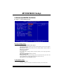
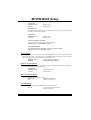
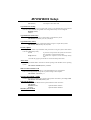
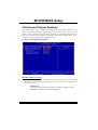
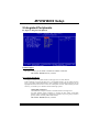
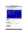
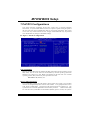
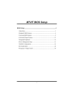
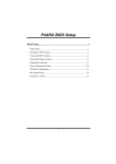
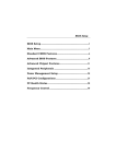
M7VIW BIOS Setup BIOS Setup .......................................................................................1 1 Main Menu ................................................................................................... 3 2 Standard CMOS Features ............................................................................. 6 3 Advanced BIOS Features ............................................................................. 9 4 Advanced Chipset Features ........................................................................ 13 5 Integrated Peripherals ................................................................................. 17 6 Power Management Setup .......................................................................... 21 7 PnP/PCI Configurations.............................................................................. 25 8 PC Health Status ......................................................................................... 28 9 Frequency Control ...................................................................................... 30 i M7VIW BIOS Setup BIOS Setup Introduction This manual discussed Award™ Setup program built into the ROM BIOS. The Setup program allows users to modify the basic system configuration. This special information is then stored in battery-backed RAM so that it retains the Setup information when the power is turned off. The Award BIOS™ installed in your computer system’s ROM (Read Only Memory) is a custom version of an industry standard BIOS. This means that it supports Intel Pentium ® 4 processor input/output system. The BIOS provides critical low-level support for standard devices such as disk drives and serial and parallel ports. Adding important has customized the Award BIOS™, but nonstandard, features such as virus and password protection as well as special support for detailed fine-tuning of the chipset controlling the entire system. The rest of this manual is intended to guide you through the process of configuring your system using Setup. Plug and Play Support These AWARD BIOS supports the Plug and Play Version 1.0A specification. ESCD (Extended System Configuration Data) write is supported. EPA Green PC Support This AWARD BIOS supports Version 1.03 of the EPA Green PC specification. APM Support These AWARD BIOS supports Version 1.1&1.2 of the Advanced Power Management (APM) specification. Power management features are implemented via the System Management Interrupt (SMI). Sleep and Suspend power management modes are supported. Power to the hard disk drives and video monitors can be managed by this AWARD BIOS. ACPI Support Award ACPI BIOS support Version 1.0 of Advanced Configuration and Power interface specification (ACPI). It provides ASL code for power management and device configuration capabilities as defined in the ACPI specification, developed by Microsoft, Intel and Toshiba. 1 M7VIW BIOS Setup PCI Bus Support This AWARD BIOS also supports Version 2.1 of the Intel PCI (Peripheral Component Interconnect) local bus specification. DRAM Support DDR (Double Data Rate Synchronous DRAM) are supported. Supported CPUs This AWARD BIOS supports the AMD Socket CPU. Using Setup In general, you use the arrow keys to highlight items, press <Enter> to select, use the <PgUp> and <PgDn> keys to change entries, press <F1> for help and press <Esc> to quit. The following table provides more detail about how to navigate in the Setup program by using the keyboard. Keystroke Up arrow Down arrow Left arrow Right arrow Move Enter PgUp key PgDn key + Key - Key Esc key F1 key F5 key F6 key F7 key F10 key Function Move to previous item Move to next item Move to the item on the left (menu bar) Move to the item on the right (menu bar) Move to the item you desired Increase the numeric value or make changes Decrease the numeric value or make changes Increase the numeric value or make changes Decrease the numeric value or make changes Main Menu – Quit and not save changes into CMOS Status Page Setup Menu and Option Page Setup Menu – Exit Current page and return to Main Menu General help on Setup navigation keys Load previous values from CMOS Load the fail-safe defaults from BIOS default table Load the optimized defaults Save all the CMOS changes and exit 2 M7VIW BIOS Setup 1 Main Menu Once you enter Award BIOS™ CMOS Setup Utility, the Main Menu will appear on the screen. The Main Menu allows you to select from several setup functions. Use the arrow keys to select among the items and press <Enter> to accept and enter the sub-menu. !! WARNING !! The information about BIOS defaults on manual (Figure 1,2,3,4,5,6,7,8,9) is just for reference, please refer to the BIOS installed on board, for update information. Figure 1. Main Menu Standard CMOS Features This submenu contains industry standard configurable options. Advanced BIOS Features This submenu allows you to configure enhanced features of the BIOS. 3 M7VIW BIOS Setup Advanced Chipset Features This submenu allows you to configure special chipset features. Integrated Peripherals This submenu allows you to configure certain IDE hard drive options and Programmed Input/ Output features. Power Management Setup This submenu allows you to configure the power management features. PnP/PCI Configurations This submenu allows you to configure certain “Plug and Play” and PCI options. PC Health Status This submenu allows you to monitor the hardware of your system. Frequency/Voltage Control This submenu allows you to change CPU Vcore Voltage and CPU/PCI clock. (However, this function is strongly recommended not to use. Not properly change the voltage and clock may cause CPU or M/B damage!) Load Optimized Defaults This selection allows you to reload the BIOS when the system is having problems particularly with the boot sequence. These configurations are factory settings optimized for this system. A confirmation message will be displayed before defaults are set. Set Supervisor Password Setting the supervisor password will prohibit everyone except the supervisor from making changes using the CMOS Setup Utility. You will be prompted with to enter a password. 4 M7VIW BIOS Setup Set User Password If the Supervisor Password is not set, then the User Password will function in the same way as the Supervisor Password. If the Supervisor Password is set and the User Password is set, the “User” will only be able to view configurations but will not be able to change them. Save & Exit Setup Save all configuration changes to CMOS(memory) and exit setup. Confirmation message will be displayed before proceeding. Exit Without Saving Abandon all changes made during the current session and exit setup. message will be displayed before proceeding. Upgrade BIOS This submenu allows you to upgrade bios. 5 confirmation M7VIW BIOS Setup 2 Standard CMOS Features The items in Standard CMOS Setup Menu are divided into 10 categories. Each category includes no, one or more than one setup items. Use the arrow keys to highlight the item and then use the<PgUp> or <PgDn> keys to select the value you want in each item. Figure 2. Standard CMOS Setup 6 M7VIW BIOS Setup Main Menu Selections This table shows the selections that you can make on the Main Menu. Item Options Date mm : dd : yy Set the system date. Note that the ‘Day’ automatically changes when you set the date. Time hh : mm : ss Set the clock. IDE Primary Master Options are in its sub menu. Press <Enter> to enter the sub menu of detailed options IDE Primary Slave Options are in its sub menu. Press <Enter> to enter the sub menu of detailed options. IDE Secondary Master Options are in its sub menu. Press <Enter> to enter the sub menu of detailed options. IDE Secondary Slave Options are in its sub menu. Press <Enter> to enter the sub menu of detailed options. Drive A 360K, 5.25 in Drive B 1.2M, 5.25 in Select the type of floppy disk drive installed in your system. 720K, 3.5 in Description system internal 1.44M, 3.5 in 2.88M, 3.5 in None Video EGA/VGA CGA 40 CGA 80 MONO 7 Select the default video device. M7VIW BIOS Setup Item Options Description Halt On All Errors Select the situation in which No Errors you want the BIOS to stop All, but Keyboard All, but Diskette the POST process and notify you. All, but Disk/ Key Base Memory N/A Displays the amount of conventional memory detected during boot up. Extended Memory N/A Displays the amount of extended memory detected during boot up. Total Memory N/A Displays the total memory available in the system. 8 M7VIW BIOS Setup 3 Advanced BIOS Features Figure 3. Advanced BIOS Setup Boot Seq & Floppy Setup First/ Second/ Third/ Boot Other Device These BIOS attempt to load the operating system from the device in the sequence selected in these items. The Choices: Floppy, LS120, HDD-0, SCSI, CDROM, HDD-1, HDD-2, HDD-3, ZIP100, LAN, Disabled. Swap Floppy Drive For systems with two floppy drives, this option allows you to swap logical drive assignments. The Choices: Disabled (default), Enabled. Boot Up Floppy Seek Enabling this option will test the floppy drives to determine if they have 40 or 80 tracks. Disabling this option reduces the time it takes to boot-up. The Choices: Disabled, Enabled (default). Cache&Shadow Setup CPU Internal Cache Choosing “enable” in this option will make the memory access time faster. 9 M7VIW BIOS Setup The Choices: Enabled (default) Disabled Enable cache. Disable cache. External Cache For improving performance you can select enable in this option. It will make the secondary cache come into effect. The Choices: Enabled (default) Disabled Enable cache. Disable cache. CPU L2 Cache ECC Checking CPU L2 Cache ECC Checking is enable or disable. The Choices: Disabled, Enabled (default). Video BIOS Shadow This option enable Video Bios to copy into shadow RAM. The Choices: Disabled, Enabled (default). Virus Warning This option allows you to choose the Virus Warning feature that is used to protect the IDE Hard Disk boot sector. If this function is enabled and someone attempt to write data into this area, BIOS will show a warning message on the screen. Disabled (default) Virus protection is disabled. Enabled Virus protection is activated. Quick Power On Self Test Enabling this option will cause an abridged version of the Power On Self-Test (POST) to execute after you power up the computer. The Choices: Enabled (default) Enable quick POST. Disabled Normal POST. Boot Up NumLock Status Selects the NumLock. State after power on. On (default) Numpad is number keys. Off Numpad is arrow keys. Gate A20 Option Select if chipset or keyboard controller should control Gate A20. Normal A pin in the keyboard controller controls Gate A20. 10 M7VIW BIOS Setup Fast (default) Lets chipset control Gate A20. Typematic Rate Setting When a key is held down, the keystroke will repeat at a rate determined by the keyboard controller. When enabled, the typematic rate and typematic delay can be configured. Disabled (default) Enabled Typematic Rate (Chars/Sec) Sets the rate at which a keystroke is repeated when you hold the key down. The Choices: 6 (default), 8,10,12,15,20,24,30. Typematic Delay (Msec) Sets the delay time after the key is held down before it begins to repeat the keystroke. The Choices: 250 (default), 500,750,1000. Security Option This option will enable only individuals with passwords to bring the system online and/or to use the CMOS Setup Utility. System A password is required for the system to boot and is also required to access the Setup Utility. Setup (default) A password is required to access the Setup Utility only. This will only apply if passwords are set from the Setup main menu. APIC Mode By selecting Enabled enables ACPI device mode reporting from the BIOS to the operating system. The Choices: Enabled (default), Disabled. MPS Version Control For OS The BIOS supports version 1.1 and 1.4 of the Intel multiprocessor specification. Select version supported by the operation system running on this computer. The Choices: 1.4 (default), 1.1. OS Select For DRAM > 64MB A choice other than Non-OS2 is only used for OS2 systems with memory exceeding 64MB. The Choices: Non-OS2 (default), OS2. Video BIOS Shadow Determines whether video BIOS will be copied to RAM for faster execution. The Choices: Enabled (default) Optional ROM is enabled. Disabled Optional ROM is disabled. Summary Screen Show 11 M7VIW BIOS Setup This item allows you to enable/ disable display the Summary Screen Show. The Choices: Disabled (default), Enabled. 12 M7VIW BIOS Setup 4 Advanced Chipset Features This submenu allows you to configure the specific features of the chipset installed on your system. This chipset manage bus speeds and access to system memory resources, such as DRAM. It also coordinates communications with the PCI bus. The default settings that came with your system have been optimized and therefore should not be changed unless you are suspicious that the settings have been changed incorrectly. Figure 4. Advanced Chipset Setup DRAM Clock/Drive Control To control the Clock/Drive. If you highlight the literal “Press Enter” next to the “DRAM Clock/Drive Control” label and then press the enter key, it will take you a submenu with the following options: DRAM Clock This item determines DRAM clock following 100MHz, 133MHz or By SPD. The Choices: 100MHz, 133MHz, By SPD (default). 13 M7VIW BIOS Setup DRAM Timing This item determines DRAM clock/ timing follow SPD or not. The Choices: By SPD (default), Manual. DRAM CAS Latency When DRAM is installed, the number of clock cycles of CAS latency depends on the DRAM timing. The Choices: 2.5 (default), 2. Bank Interleave This item allows you to enable or disable the bank interleave feature. The Choices: Disabled (default), 2 bank, 4 bank. Precharge to Active (Trp) This items allows you to specify the delay from precharge command to activate command. The Choices: 2T, 3T (default). Active to Precharge (Tras) This items allows you to specify the minimum bank active time. The Choices: 6T (default), 5T. Active to CMD (Trcd) Use this item to specify the delay from the activation of a bank to the time that a read or write command is accepted. The Choices: 2T, 3T (default). DRAM Burst Length This item allows you to choose DRAM Burst Length The Choices: 4 (Default), 8. DRAM Queue Depth This item permits to place the depths of the memory. the better is this function. The Choices: 4 level (default), 2 level, 3 level. The deeper the depth is, DRAM Command Rate This item controls clock cycle that must occur between the last valid write operation and the next command. The Choices: 1T Command, 2T Command (default). AGP & P2P Bridge Control If you highlight the literal “Press Enter” next to the “AGP & P2P Bridge Control” label and then press the enter key, it will take you a submenu with the following options: AGP Aperture Size Select the size of the Accelerated Graphics Port (AGP) aperture. The aperture is 14 M7VIW BIOS Setup a portion of the PCI memory address range dedicated for graphics memory address space. Host cycles that hit the aperture range are forwarded to the AGP without any translation. The Choices: 64M (default), 256M, 128M, 32M, 16M, 8M, 4M. AGP Mode This item allows you to select the AGP Mode. The Choices: 4X (default), 2X, 1X. AGP Driving Control By choosing “Auto” the system BIOS will the AGP output Buffer Drive strength P Ctrl by AGP Card. By choosing “Manual”, it allows user to set AGP output Buffer Drive strength P Ctrl by manual. The Choices: Auto (default), Manual. AGP Driving Value While AGP driving control item set to “Manual”, it allows user to set AGP driving. The Choices: DA (default). AGP Fast Write The Choices: Enabled, Disabled (default). AGP Master 1 WS Write When Enabled, writes to the AGP (Accelerated Graphics Port) are executed with one-wait states. The Choices: Disabled (default), Enabled. AGP Master 1 WS Read When Enabled, read to the AGP (Accelerated Graphics Port) are executed with one wait states. The Choices: Disabled (default), Enabled. CPU & PCI Bus Control If you highlight the literal “Press Enter” next to the “CPU & PCI Bus Control” label and then press the enter key, it will take you a submenu with the following options: PCI1 Master 0 WS Write When enabled, writes to the PCI bus are executed with zero-wait states. The Choices: Enabled (default), Disabled. PCI2 Master 0 WS Write When enabled, writes to the AGP bus are executed with zero-wait states. The Choices: Enabled (default), Disabled. 15 M7VIW BIOS Setup PCI1 Post Write When Enabled, CPU writes are allowed to post on the PCI bus. The Choices: Enabled (default), Disabled. PCI2 Post Write When Enabled, CPU writes are allowed to post on the AGP bus. The Choices: Enabled (default), Disabled. PCI Delay Transaction The chipset has an embedded 32-bit posted write buffer to support delay transactions cycles. Select Enabled to support compliance with PCI specification. The Choices: Enabled (default), Disabled. Memory Hole When enabled, you can reserve an area of system memory for ISA adapter ROM. When this area is reserved, it cannot be cached. Refer to the user documentation of the peripheral you are installing for more information. The Choices: Disabled (default), 15M – 16M. System BIOS Cacheable Selecting the “Enabled” option allows caching of the system BIOS ROM at F0000h-FFFFFh, which can improve system performance. However, any programs writing to this area of memory will cause conflicts and result in system errors. The Choices: Enabled, Disabled (default). Video RAM Cacheable Enabling this option allows caching of the video RAM, resulting a better system performance. However, if any program writes to this memory area, a system error may result. The Choices: Disabled (default), Enabled. 16 M7VIW BIOS Setup 5 Integrated Peripherals Figure 5. Integrated Peripherals USB2.0 Support This option allows you to enable or disable the USB2.0 Controller. The Choices: Enabled (default), Disabled. VIA OnChip IDE Device The chipset contains a PCI IDE interface with support for two IDE channels. Select “Enabled” to activate the first and / or second IDE interface. If you install a primary and / or secondary add-in IDE interface, select “Disabled” to deactivate an interface. If you highlight the literal “Press Enter” next to the “Onchip IDE Control” label and then press the enter key, it will take you a submenu with the following options: OnChip IDE Channel 0/1 The motherboard chipset contains a PCI IDE interface with support for two IDE channels. Select “Enabled” to activate the first and/or second IDE interface. Select “Disabled” to deactivate an interface if you are going to install a primary and/or secondary add-in IDE interface. The Choices: Enabled (default), Disabled. 17 M7VIW BIOS Setup IDE Prefetch Mode The “onboard” IDE drive interfaces supports IDE prefetching for faster drive access. If the interface does not support prefetching. If you install a primary and/or secondary add-in IDE interface, set this option to “Disabled”. The Choices: Enabled (default), Disabled. IDE Primary / Secondary Master / Slave PIO The IDE PIO (Programmed Input / Output) fields let you set a PIO mode (0-4) for each of the IDE devices that the onboard IDE interface supports. Modes 0 through 4 provides successively increased performance. In Auto mode, the system automatically determines the best mode for each device. The Choices: Auto (default), Mode0, Mode1, Mode2, Mode3, Mode4. IDE Primary / Secondary Master / Slave UDMA Ultra DMA/100 functionality can be implemented if it is supported by the IDE hard drives in your system. As well, your operating environment requires a DMA driver (Windows 95 OSR2 or a third party IDE bus master driver). If your hard drive and your system software both support Ultra DMA/100, select Auto to enable BIOS support. The Choices: Auto (default), Disabled. VIA OnChip PCI Device If you highlight the literal “Press Enter” next to the “OnChip PCI Device” label and then press the enter key, it will take you a submenu with the following options: VIA-3058 AC97 Audio This option allows you to control the onboard AC97 audio. The Choices: Auto (default), Disabled. VIA-3068 MC97 Modem This option allows you to control the onboard MC97 modem. The Choices: Auto (default), Disabled. VIA-3043 OnChip LAN This option allows you to control the onboard LAN. The Choices: Enabled (default), Disabled. Onboard LAN Boot ROM This item allows you to enable or disable Onboard LAN Boot ROM. The Choices: Disabled (default), Enabled. Super IO Device If you highlight the literal “Press Enter” next to the “Super IO Device” label and then press the enter key, it will take you a submenu with the following options: Onboard FDC Controller 18 M7VIW BIOS Setup Select Enabled if your system has a floppy disk controller (FDC) installed on the system board and you wish to use it. If install and FDC or the system has no floppy drive, select Disabled in this field. The Choices: Enabled (default), Disabled. Onboard Serial Port 1 Select an address and corresponding interrupt for the first and second serial ports. The Choices: Disabled, 3F8/IRQ4 (default), 2F8/IRQ3, 3E8/IRQ4, 2E8/IRQ3, Auto. Onboard Serial Port 2 Select an address and corresponding interrupt for the first and second serial ports. The Choices: Disabled (default), 2F8/IRQ3, 3F8/IRQ4, 3E8/IRQ4, 2E8/IRQ3, Auto. UART Mode Select This item allows you to determine which Infra Red (IR) function of onboard I/O chip. The Choices: Normal, ASKIR, IrDA (default). UR2 Duplex Mode Select the value required by the IR device connected to the IR port. Full-duplex mode permits simultaneous two-direction transmission. Half-duplex mode permits transmission in one direction only at a time. The Choices: Half (default), Full. Onboard Parallel Port This item allows you to determine access onboard parallel port controller with which I/O address. The Choices: 378/IRQ7 (default), 278/IRQ5, 3BC/IRQ7, Disabled. Parallel Port Mode The default value is EPP. SPP (default) EPP ECP ECP+EPP Using Parallel port as Standard Printer Port. Using Parallel port as Enhanced Parallel Port. Using Parallel port as Extended Capabilities Port Using Parallel port as ECP & EPP mode. ECP Mode Use DMA Select a DMA Channel for the port. The Choices: 3 (default), 1. Game Port Address Game Port I/O Address. 19 M7VIW BIOS Setup The Choices: 201 (default), 209, Disabled. Midi Port Address Midi Port Base I/O Address. The Choices: 330 (default), 300, 290, Disabled. Midi Port IRQ This determines the IRQ in which the Midi Port can use. The Choices: 10 (default), 5. Init Display First With systems that have multiple video cards, this option determines whether the primary display uses a PCI Slot or an AGP Slot. The Choices: PCI Slot (default), AGP. OnChip USB Controller This option should be enabled if your system has a USB installed on the system board. You will need to disable this feature if you add a higher performance controller. The Choices: All enabled (default). USB Keyboard Support Enables support for USB attached keyboards. The Choices: Disabled (default), Enabled. IDE HDD Block Mode Block mode is also called block transfer, multiple commands, or multiple sector read / write. If your IDE hard drive supports block mode (most new drives do), select Enabled for automatic detection of the optimal number of block mode (most new drives do), select Enabled for automatic detection of the optimal number of block read / write per sector where the drive can support. The Choices: Enabled (default), Disabled. 20 M7VIW BIOS Setup 6 Power Management Setup The Power Management Setup Menu allows you to configure your system to utilize energy conservation and power up/power down features. Figure 6. Power Management Setup ACPI fnction This item displays the status of the Advanced Configuration and Power Management (ACPI). The Choices: Enabled (default), Disabled. ACPI Suspend Type The item allows you to select the suspend type under the ACPI operating system. The Choices: S1 (POS) (default) Power on Suspend S3 (STR) Suspend to RAM S1 & S3 POS+STR Power Management This category allows you to select the type (or degree) of power saving and is directly related to the following modes: 1.HDD Power Down. 2.Suspend Mode. 21 M7VIW BIOS Setup There are four options of Power Management, three of which have fixed mode settings Min. Power Saving Minimum power management. Suspend Mode = 1 hr. HDD Power Down = 15 min Max. Power Saving Maximum power management only available for sl CPU’s. Suspend Mode = 1 min. HDD Power Down = 1 min. User Defined (default) Allows you to set each mode individually. When not disabled, each of the ranges are from 1 min. to 1 hr. except for HDD Power Down which ranges from 1 min. to 15 min. and disable. HDD Power Down When enabled, the hard disk drive will power down and after a set time of system inactivity. All other devices remain active. The Choices: Disabled (default), 1 Min, 2 Min, 3 Min, 4 Min, 5 Min, 6 Min, 7 Min, 8 Min, 9 Min, 10 Min, 11 Min, 12 Min, 13 Min, 14 Min, 15 Min. Suspend Mode When enabled and when after the set time of system inactivity, all devices except the CPU will be shut off. The Choices: Disabled (default), 1 Min, 2 Min, 4 Min, 6 Min, 8 Min, 10 Min, 20 Min, 30 Min, 40 Min, and 1Hour. Video Off Option This field determines when to activate the video off feature for monitor power management. The Choices: Suspend→Off (default), Always on, All Modes→Off. Video Off Method This option determines the manner in which the monitor is goes blank. V/H SYNC+Blank (default) This selection will cause the system to turn off the vertical and horizontal synchronization ports and write blanks to the video buffer. Blank Screen 22 M7VIW BIOS Setup This option only writes blanks to the video buffer. DPMS Initial display power management signaling. Modem Use IRQ This determines the IRQ, which can be applied in MODEM use. The Choices: 3 (default),4 / 5 / 7 / 9 / 10 / 11 / NA. Soft-Off by PWR-BTTN Pressing the power button for more than 4 seconds forces the system to enter the Soft-Off state when the system has “hung.” The Choices: Delay 4 Sec, Instant-Off (default). Run VGABIOS if S3 Resume Choosing Enabled will make BIOS run VGA BIOS to initialize the VGA card when system wakes up from S3 state . The system time is shortened if you disable the function , but system will need AGP driver to initialize the card . So , if the AGP driver of the VGA card does not support the initialization feature , the display may work abnormally or not function after S3 . The Choices:Auto (default), Yes, No. IRQ/Event Activity Detect If you highlight the literal “Press Enter” next to the “IRQ/Event Activity Detect” label and then press the enter key, it will show you a submenu with the following options: VGA When set to On, any event occurring at a VGA Port will awaken a system which has been powered down. The Choices: Off (default), On. LPT & COM When this option is set to On, any event occurring at a COM(serial)/LPT (printer) port will awaken a system which has been powered down. The Choices: LPT/COM (default), COM, LPT, NONE. HDD & FDD When this option is set to On, any event occurring on a hard drive or a floppy drive will awaken a system which has been powered down. The Choices: On (default), Off. PCI Master When set to On, you need a LAN add-on card which supports the power function. It should also support the wake-up on LAN jump. The Choices: Off (default), On. 23 M7VIW BIOS Setup PowerOn by PCI Card When you select Enabled, a PME signal from PCI card returns the system to Full ON state. The Choices: Disabled (default), Enabled. Wake Up On LAN/Ring To use this function, you need a LAN add-on card which support power on function. It should also support the wake-up on LAN jump. Disabled (default) Wake up on LAN/Ring not supported. Enabled Wake up on LAN/Ring supported. RTC Alarm Resume When “Enabled”, you can set the date and time at which the RTC (real-time clock) alarm awakens the system from Suspend mode. The Choices: Enabled, Disabled (default). IRQs Activity Monitoring Press Enter to access another sub menu used to configure the different wake up events (i.e. wake on LPT & COMM activity). Primary INTR IRQ3 (COM2) IRQ4 (COM1) IRQ5 (LPT2) IRQ6 (Floppy Disk) IRQ7 (LPT1) IRQ8 (RTC Alarm) IRQ9 (IRQ2 Redir) IRQ10 (Reserved) IRQ11 (Reserved) IRQ12 (PS/2 Mouse) IRQ13 (Coprocessor) IRQ14 (Hard Disk) IRQ15 (Reserved) On Enabled Enabled Enabled Enabled Enabled Disabled Disabled Disabled Disabled Enabled Enabled Enabled Disabled 24 M7VIW BIOS Setup 7 PnP/PCI Configurations This section describes configuring the PCI bus system. PCI, or Personal Computer Interconnect, is a system which allows I/O devices to operate at speeds nearing the speed of the CPU itself uses when communicating with its own special components. This section covers some very technical items and it is strongly recommended that only experienced users should make any changes to the default settings. Figure 7. PnP/PCI Configurations PNP OS Installed When set to YES, BIOS will only initialize the PnP cards used for the boot sequence (VGA, IDE, SCSI). The rest of the cards will be initialized by the PnP operating system like Window™ 95. When set to NO, BIOS will initialize all the PnP cards. For non-PnP operating systems (DOS, Netware™), this option must set to NO. The Choices: No (default), Yes. Reset Configuration Data The system BIOS supports the PnP feature which requires the system to record which resources are assigned and protects resources from conflict. Every peripheral device has a node, which is called ESCD. This node records which resources are assigned to it. The system needs to record and update ESCD to the memory locations. These locations (4K) are reserved in the system BIOS. If the Disabled (default) option is chosen, the system‘s 25 M7VIW BIOS Setup ESCD will update only when the new configuration varies from the last one. If the Enabled option is chosen, the system is forced to update ESCDs and then is automatically set to the “Disabled” mode. The above settings will be shown on the screen only if “Manual” is chosen for the resources controlled by function. Legacy is the term, which signifies that a resource is assigned to the ISA Bus and provides non-PnP ISA add-on cards. PCI / ISA PnP signifies that a resource is assigned to the PCI Bus or provides for ISA PnP add-on cards and peripherals. The Choices: Disabled (default), Enabled. Resources Controlled By By Choosing “Auto(ESCD)” (default), the system BIOS will detect the system resources and automatically assign the relative IRQ and DMA channel for each peripheral.By Choosing “Manual”, the user will need to assign IRQ & DMA for add-on cards. Be sure that there are no IRQ/DMA and I/O port conflicts. IRQ Resources This submenu will allow you to assign each system interrupt a type, depending on the type of device using the interrupt. When you press the “Press Enter” tag, you will be directed to a submenu that will allow you to configure the system interrupts. This is only configurable when “Resources Controlled By” is set to “Manual”. IRQ-3 IRQ-4 IRQ-5 IRQ-7 IRQ-9 IRQ-10 IRQ-11 IRQ-12 IRQ-14 IRQ-15 assigned to assigned to assigned to assigned to assigned to assigned to assigned to assigned to assigned to assigned to PCI Device PCI Device PCI Device PCI Device PCI Device PCI Device PCI Device PCI Device PCI Device PCI Device PCI / VGA Palette Snoop Choose Disabled or Enabled. Some graphic controllers which are not VGA compatible take the output from a VGA controller and map it to their display as a way to provide boot information and VGA compatibility. However, the color information coming from the VGA controller is drawn from the palette table inside the VGA controller to generate the proper colors, and the graphic controller needs to know what is in the palette of the VGA controller. To do this, the non-VGA graphic controller watches for the Write access to the VGA palette and registers the snoop data. In PCI based systems, where the VGA controller is on the PCI bus and a non-VGA graphic controller is on an ISA bus, the Write Access to the palette will not show up on the 26 M7VIW BIOS Setup ISA bus if the PCI VGA controller responds to the Write. In this case, the PCI VGA controller should not respond to the Write, it should only snoop the data and permit the access to be forwarded to the ISA bus. The non-VGA ISA graphic controller can then snoop the data on the ISA bus. Unless you have the above situation, you should disable this option. Disabled (default) Disables the function. Enabled Enables the function. Assign IRQ For VGA Lets the user choose which IRQ to assign for the VGA. The Choices: Enabled (default), Disabled. Assign IRQ For USB Lets the user choose which IRQ to assign for the USB. The Choices: Enabled (default), Disabled. 27 M7VIW BIOS Setup 8 PC Health Status Figure 8. PC Health Status Shutdown Temperature This item allows you to set up the CPU shutdown Temperature. This item only effective under Windows 98 ACPI mode. The Choices: Disabled (Default), Enabled. CPU Voltage/+3.3V/+5V/+12V/-12V/-5V Detect the system’s voltage status automatically. Current CPU Temperature This field displays the current temperature of the CPU. Current CPUFAN Speed This field displays the current speed of CPU fan. Current SYSFAN Speed This field displays the current speed SYSTEM fan. 28 M7VIW BIOS Setup Show H/W Monitor in POST If your computer contains a monitoring system, it will show PC health status during POST stage. The item offers several delay time for you to choose. The Choices: Enabled (default), Disabled. The Choices: Disabled (default), 60OC/140OF, 65OC/149OF, 70OC/158OF, 75OC/167OF. Chassis open warning This item allows you to enable or disable Chassis Open Warning beep. The Choices: Disabled (Default), Enabled. 29 M7VIW BIOS Setup 9 Frequency Control Figure 9. Frequency/ Voltage Control CPU Clock This item allows you to select CPU Clock, and CPU over clocking. If unfortunately, the system’s frequency that you are selected is not functioning, there are two methods of booting-up the system. Method 1: Clear the COMS data by setting the JCOMS1 ((2-3) closed)) as “ON” status. All the CMOS data will be loaded as defaults setting. Method 2: Press the <Insert> key and Power button simultaneously, after that keep-on pressing the <Insert> key until the power-on screen showed. This action will boot-up the system according to FSB of the processor. ※ It’s strongly recommended to set CPU Vcore and clock in default setting. If the CPU Vcore and clock are not in default setting, it may cause CPU or M/B damage. 30