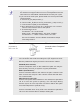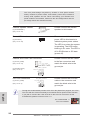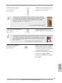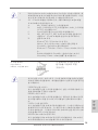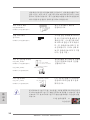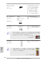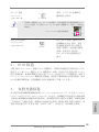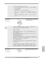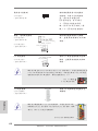
1
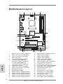
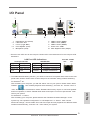
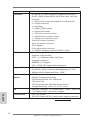
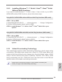
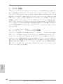
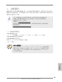
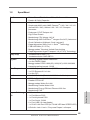
Copyright Notice: No part of this installation guide may be reproduced, transcribed, transmitted, or translated in any language, in any form or by any means, except duplication of documentation by the purchaser for backup purpose, without written consent of ASRock Inc. Products and corporate names appearing in this guide may or may not be registered trademarks or copyrights of their respective companies, and are used only for identification or explanation and to the owners’ benefit, without intent to infringe. Disclaimer: Specifications and information contained in this guide are furnished for informational use only and subject to change without notice, and should not be constructed as a commitment by ASRock. ASRock assumes no responsibility for any errors or omissions that may appear in this guide. With respect to the contents of this guide, ASRock does not provide warranty of any kind, either expressed or implied, including but not limited to the implied warranties or conditions of merchantability or fitness for a particular purpose. In no event shall ASRock, its directors, officers, employees, or agents be liable for any indirect, special, incidental, or consequential damages (including damages for loss of profits, loss of business, loss of data, interruption of business and the like), even if ASRock has been advised of the possibility of such damages arising from any defect or error in the guide or product. This device complies with Part 15 of the FCC Rules. Operation is subject to the following two conditions: (1) this device may not cause harmful interference, and (2) this device must accept any interference received, including interference that may cause undesired operation. English CALIFORNIA, USA ONLY The Lithium battery adopted on this motherboard contains Perchlorate, a toxic substance controlled in Perchlorate Best Management Practices (BMP) regulations passed by the California Legislature. When you discard the Lithium battery in California, USA, please follow the related regulations in advance. “Perchlorate Material-special handling may apply, see www.dtsc.ca.gov/hazardouswaste/perchlorate” ASRock Website: http://www.asrock.com Published August 2012 Copyright©2012 ASRock INC. All rights reserved. ASRock 970 Pro2 Motherboard 1 Motherboard Layout 2 3 PWR_FAN1 CPU_FAN1 1 5 4 7 6 19.1cm (7.5-in) PS2 Mouse PS2 Keyboard ErP/EuP Ready AM3+ 140W CPU Top: LINE IN DDR3_B2 (64 bit, 240-pin module) FSB800 DDR3_B1 (64 bit, 240-pin module) AMD 770 Chipset CMOS BATTERY 30.5cm (12.0-in) Bottom: MIC IN Support 8-Core CPU Top: RJ-45 Center: FRONT USB 2.0 T: USB0 B: USB1 FSB800 DDR3 1866 USB 2.0 T: USB0 B: USB1 DDR3_A2 (64 bit, 240-pin module) SOCKET AM3b USB 2.0 T: USB2 B: USB3 DDR3_A1 (64 bit, 240-pin module) COM1 ATX12V1 8 CLRCMOS1 1 36 35 PCIE1 970 Pro2 9 34 IDE1 33 PCIE2 X Fast RAM X Fast USB LAN PHY 32 30 29 Designed in Taipei 31 PCIE3 X Fast LAN 10 PCIE4 AMD SB710 Chipset RoHS Super I/O 8Mb BIOS 12 SATAII_6(PORT 5) 13 14 USB8_9 AUDIO CODEC 1 1 SATAII_5(PORT 4) PCI2 USB6_7 SATAII_2(PORT 1) SATAII_4(PORT 3) SATAII_1(PORT 0) SATAII_3(PORT 2) HDMI_SPDIF1 28 1 1 PLED PWRBTN 26 25 English ATX 12V Power Connector (ATX12V1) Power Fan Connector (PWR_FAN1) CPU Fan Connector (CPU_FAN1) AM3+ CPU Socket CPU Heatsink Retention Module 2 x 240-pin DDR3 DIMM Slots (Dual Channel: DDR3_A1, DDR3_B1) 2 x 240-pin DDR3 DIMM Slots (Dual Channel: DDR3_A2, DDR3_B2) Northbridge Controller ATX Power Connector (ATXPWR1) Chassis Fan Connector (CHA_FAN1) Southbridge Controller SPI Flash Memory (8Mb) SATA2 Connector (SATA2_6 (PORT 5)) SATA2 Connector (SATA2_5 (PORT 4)) SATA2 Connector (SATA2_4 (PORT 3)) SATA2 Connector (SATA2_3 (PORT 2)) SATA2 Connector (SATA2_2 (PORT 1)) USB4_5 PLED1 SPEAKER1 1 FLOPPY1 27 1 PANEL 1 CD1 HD_AUDIO1 1 2 11 PCI1 IR1 1 2 3 4 5 6 7 8 9 10 11 12 13 14 15 16 17 CHA_FAN1 1 HDLED RESET 1 15 16 24 23 22 21 20 19 18 17 18 19 20 21 22 23 24 25 26 27 28 29 30 31 32 33 34 35 36 SATA2 Connector (SATA2_1 (PORT 1)) USB 2.0 Header (USB6_7) USB 2.0 Header (USB4_5) USB 2.0 Header (USB8_9) System Panel Header (PANEL1) Power LED Header (PLED1) Chassis Speaker Header (SPEAKER 1) Floppy Connector (FLOPPY1) Internal Audio Connector: CD1 Front Panel Audio Header (HD_AUDIO1) HDMI_SPDIF Header (HDMI_SPDIF1) Infrared Module Header (IR1) PCI Slots (PCI1-2) PCI Express 2.0 x1 Slot (PCIE4) PCI Express 2.0 x16 Slot (PCIE3) PCI Express 2.0 x1 Slot (PCIE2) IDE1 Connector (IDE1) PCI Express 2.0 x1 Slot (PCIE1) Clear CMOS Jumper (CLRCMOS1) ASRock 970 Pro2 Motherboard I/O Panel 1 2 3 4 5 10 1 * 2 3 ** 4 5 8 9 PS/2 Mouse Port (Green) LAN RJ-45 Port Line In (Light Blue) Front Speaker (Lime) Microphone (Pink) 7 6 7 8 9 10 6 USB 2.0 Ports (USB01) USB 2.0 Port (USB01) USB 2.0 Ports (USB23) Serial Port: COM1 PS/2 Keyboard Port (Purple) * There are two LED next to the LAN port. Please refer to the table below for the LAN port LED indications. LAN Port LED Indications Activity/Link LED Status Description Off No Link Blinking Data Activity On Link Status Off Orange Green SPEED LED Description 10Mbps connection 100Mbps connection 1Gbps connection ACT/LINK SPEED LED LED LAN Port ** To enable Multi-Streaming function, you need to connect a front panel audio cable to the front panel audio header. Please refer to below steps for the software setting of Multi-Streaming. For Windows® XP: After restarting your computer, you will find “Mixer” tool on your system. Please select “Mixer ToolBox” , click “Enable playback multi-streaming”, and click “ok”. Choose “2CH” or ASRock 970 Pro2 Motherboard English “4CH” and then you are allowed to select “Realtek HDA Primary output” to use Rear Speaker and Front Speaker, or select “Realtek HDA Audio 2nd output” to use front panel audio. Then reboot your system. For Windows® 7 / VistaTM: After restarting your computer, please double-click “Realtek HD Audio Manager” on the system tray. Set “Speaker Configuration” to “Quadraphonic” or “Stereo”. Click “Device advanced settings”, choose “Make front and rear output devices playbacks two different audio streams simultaneously”, and click “ok”. Then reboot your system. 3 1. Introduction Thank you for purchasing ASRock 970 Pro2 motherboard, a reliable motherboard produced under ASRock’s consistently stringent quality control. It delivers excellent performance with robust design conforming to ASRock’s commitment to quality and endurance. This Quick Installation Guide contains introduction of the motherboard and step-bystep installation guide. More detailed information of the motherboard can be found in the user manual presented in the Support CD. Because the motherboard specifications and the BIOS software might be updated, the content of this manual will be subject to change without notice. In case any modifications of this manual occur, the updated version will be available on ASRock website without further notice. You may find the latest VGA cards and CPU support lists on ASRock website as well. ASRock website http://www.asrock.com If you require technical support related to this motherboard, please visit our website for specific information about the model you are using. www.asrock.com/support/index.asp 1.1 Package Contents ASRock 970 Pro2 Motherboard (ATX Form Factor: 12.0-in x 7.5-in, 30.5 cm x 19.1 cm) ASRock 970 Pro2 Quick Installation Guide ASRock 970 Pro2 Support CD 2 x Serial ATA (SATA) Data Cables (Optional) 1 x I/O Panel Shield ASRock Reminds You... To get better performance in Windows® 7 / 7 64-bit / VistaTM / VistaTM 64 bit, it is recommended to set the BIOS option in Storage Configuration to AHCI mode. For the BIOS setup, please refer to the “User Manual” in our support CD for details. English 4 ASRock 970 Pro2 Motherboard 1.2 Specifications CPU Chipset Memory Expansion Slot Audio LAN Rear Panel I/O - ATX Form Factor: 12.0-in x 7.5-in, 30.5 cm x 19.1 cm - All Solid Capacitor design - Support for Socket AM3+ processors - Support for Socket AM3 processors: AMD PhenomTM II X6 / X4 / X3 / X2 (except 920 / 940) / Athlon II X4 / X3 / X2 / Sempron processors - Supports 8-Core CPU - Digi Power Design - Supports CPU up to 140W - Supports AMD OverDriveTM with ACC feature (Advanced Clock Calibration) - Supports AMD’s Cool ‘n’ QuietTM Technology - FSB 2600 MHz (5.2 GT/s) - Supports Untied Overclocking Technology - Supports Hyper-Transport 3.0 (HT 3.0) Technology - Northbridge: AMD 770 - Southbridge: AMD SB710 - Dual Channel DDR3 Memory Technology - 4 x DDR3 DIMM slots - Support DDR3 1866(OC)/1600(OC)/1333/1066/800 non-ECC, un-buffered memory (see CAUTION 1) - Max. capacity of system memory: 32GB (see CAUTION 2) - 1 x PCI Express 2.0 x16 slot (PCIE3 @ x16 mode) - 3 x PCI Express 2.0 x1 slots - 2 x PCI slots - 5.1 CH HD Audio (Realtek ALC662 Audio Codec) - PCIE x1 Gigabit LAN 10/100/1000 Mb/s - Realtek RTL8111E - Supports Wake-On-LAN - Supports LAN Cable Detection - Supports Energy Efficient Ethernet 802.3az - Supports PXE English Platform I/O Panel - 1 x PS/2 Mouse Port - 1 x PS/2 Keyboard Port - 1 x Serial Port: COM1 - 6 x Ready-to-Use USB 2.0 Ports - 1 x RJ-45 LAN Port with LED (ACT/LINK LED and SPEED LED) ASRock 970 Pro2 Motherboard 5 Connector - HD Audio Jack: Line in / Front Speaker / Microphone - 6 x SATA2 3.0 Gb/s connectors, support RAID (RAID 0, RAID 1, RAID 10 and JBOD), NCQ, AHCI and “Hot Plug” functions - 1 x ATA133 IDE connector (supports 2 x IDE devices) - 1 x Floppy connector - 1 x IR header - 1 x HDMI_SPDIF header - 1 x Power LED header - 1 x CPU Fan connector (4-pin) - 1 x Chassis Fan connector (4-pin) - 1 x Power Fan connector (4-pin) - 24 pin ATX power connector - 8 pin 12V power connector - CD in header - Front panel audio connector - 3 x USB 2.0 headers (support 6 USB 2.0 ports) - 8Mb AMI Legal BIOS - Supports “Plug and Play” - ACPI 1.1 Compliance Wake Up Events - Supports jumperfree - SMBIOS 2.3.1 Support - CPU, VCCM, NB Voltage Multi-adjustment - Drivers, Utilities, AntiVirus Software (Trial Version), AMD OverDriveTM Utility, CyberLink MediaEspresso 6.5 Trial, ASRock MAGIX Multimedia Suite - OEM - CPU Temperature Sensing - Chassis Temperature Sensing - CPU/Chassis/Power Fan Tachometer - CPU Quiet Fan - CPU/Chassis/Power Fan Multi-Speed Control - Voltage Monitoring: +12V, +5V, +3.3V, Vcore - Microsoft® Windows® 7 / 7 64-bit / VistaTM / VistaTM 64-bit / XP / XP Media Center / XP 64-bit compliant - FCC, CE, WHQL - ErP/EuP Ready (ErP/EuP ready power supply is required) BIOS Feature English Support CD Hardware Monitor OS Certifications * For detailed product information, please visit our website: http://www.asrock.com 6 ASRock 970 Pro2 Motherboard WARNING Please realize that there is a certain risk involved with overclocking, including adjusting the setting in the BIOS, applying Untied Overclocking Technology, or using third-party overclocking tools. Overclocking may affect your system’s stability, or even cause damage to the components and devices of your system. It should be done at your own risk and expense. We are not responsible for possible damage caused by overclocking. CAUTION! English 1. Whether 1866/1600MHz memory speed is supported depends on the AM3/AM3+ CPU you adopt. If you want to adopt DDR3 1866/1600 memory module on this motherboard, please refer to the memory support list on our website for the compatible memory modules. ASRock website: http://www.asrock.com 2. Due to the operating system limitation, the actual memory size may be less than 4GB for the reservation for system usage under Windows® 7 / VistaTM / XP. For Windows® 64-bit OS with 64bit CPU, there is no such limitation. ASRock 970 Pro2 Motherboard 7 1.3 Unique Features ASRock OC Tuner ASRock OC Tuner is a user-friendly overclocking tool which allows you to surveil your system by hardware monitor function and overclock your hardware devices to get the best system performance under Windows® environment. ASRock Intelligent Energy Saver Featuring an advanced proprietary hardware and software design, Intelligent Energy Saver is a revolutionary technology that delivers unparalleled power savings. The voltage regulator can reduce the number of output phases to improve efficiency when the CPU cores are idle. In other words, it is able to provide exceptional power saving and improve power efficiency without sacrificing computing performance. To use Intelligent Energy Saver function, please enable Cool ‘n’ Quiet option in the BIOS setup in advance. ASRock Instant Boot ASRock Instant Boot allows you to turn on your PC in just a few seconds, provides a much more efficient way to save energy, time, money, and improves system running speed for your system. It leverages the S3 and S4 ACPI features which normally enable the Sleep/Standby and Hibernation modes in Windows® to shorten boot up time. By calling S3 and S4 at specific timing during the shutdown and startup process, Instant Boot allows you to enter your Windows® desktop in a few seconds. English ASRock Instant Flash ASRock Instant Flash is a BIOS flash utility embedded in Flash ROM. This convenient BIOS update tool allows you to update system BIOS without entering operating systems first like MSDOS or Windows®. With this utility, you can press the <F6> key during the POST or the <F2> key to enter into the BIOS setup menu to access ASRock Instant Flash. Just launch this tool and save the new BIOS file to your USB flash drive, floppy disk or hard drive, then you can update your BIOS only in a few clicks without preparing an additional floppy diskette or other complicated flash utility. Please be noted that the USB flash drive or hard drive must use FAT32/16/12 file system. 8 ASRock 970 Pro2 Motherboard ASRock OC DNA The software name itself – OC DNA literally tells you what it is capable of. OC DNA, an exclusive utility developed by ASRock, provides a convenient way for the user to record the OC settings and share with others. It helps you to save your overclocking record under the operating system and simplifies the complicated recording process of overclocking settings. With OC DNA, you can save your OC settings as a profile and share with your friends! Your friends then can load the OC profile to their own system to get the same OC settings as yours! Please be noticed that the OC profile can only be shared and worked on the same motherboard. ASRock APP Charger If you desire a faster, less restricted way of charging your Apple devices, such as iPhone/iPad/iPod Touch, ASRock has prepared a wonderful solution for you - ASRock APP Charger. Simply install the APP Charger driver, it makes your iPhone charge much quickly from your computer and up to 40% faster than before. ASRock APP Charger allows you to quickly charge many Apple devices simultaneously and even supports continuous charging when your PC enters into Standby mode (S1), Suspend to RAM (S3), hibernation mode (S4) or power off (S5). With APP Charger driver installed, you can easily enjoy the marvelous charging experience. ASRock XFast USB ASRock XFast USB can boost USB storage device performance. The performance may depend on the properties of the device. ASRock 970 Pro2 Motherboard English ASRock XFast LAN ASRock XFast LAN provides a faster internet access, which includes the benefits listed below. LAN Application Prioritization: You can configure your application’s priority ideally and/or add new programs. Lower Latency in Game: After setting online game’s priority higher, it can lower the latency in games. Traffic Shaping: You can watch Youtube HD videos and download simultaneously. Real-Time Analysis of Your Data: With the status window, you can easily recognize which data streams you are transferring currently. 9 ASRock XFast RAM ASRock XFast RAM fully utilizes the memory space that cannot be used under Windows® OS 32-bit CPU. ASRock XFast RAM shortens the loading time of previously visited websites, making web surfing faster than ever. And it also boosts the speed of Adobe Photoshop 5 times faster. Another advantage of ASRock XFast RAM is that it reduces the frequency of accessing your SSDs or HDDs in order to extend their lifespan. English 10 ASRock 970 Pro2 Motherboard 2. Installation This is an ATX form factor (12.0-in x 7.5-in, 30.5 cm x 19.1 cm) motherboard. Before you install the motherboard, study the configuration of your chassis to ensure that the motherboard fits into it. Pre-installation Precautions Take note of the following precautions before you install motherboard components or change any motherboard settings. Before you install or remove any component, ensure that the power is switched off or the power cord is detached from the power supply. Failure to do so may cause severe damage to the motherboard, peripherals, and/or components. 2. 3. 4. 5. Unplug the power cord from the wall socket before touching any component. To avoid damaging the motherboard components due to static electricity, NEVER place your motherboard directly on the carpet or the like. Also remember to use a grounded wrist strap or touch a safety grounded object before you handle components. Hold components by the edges and do not touch the ICs. Whenever you uninstall any component, place it on a grounded antistatic pad or in the bag that comes with the component. When placing screws into the screw holes to secure the motherboard to the chassis, please do not over-tighten the screws! Doing so may damage the motherboard. English 1. ASRock 970 Pro2 Motherboard 11 2.1 CPU Installation o Step 1. Unlock the socket by lifting the lever up to a 90 angle. Step 2. Position the CPU directly above the socket such that the CPU corner with the golden triangle matches the socket corner with a small triangle. Step 3. Carefully insert the CPU into the socket until it fits in place. The CPU fits only in one correct orientation. DO NOT force the CPU into the socket to avoid bending of the pins. Step 4. When the CPU is in place, press it firmly on the socket while you push down the socket lever to secure the CPU. The lever clicks on the side tab to indicate that it is locked. Lever 90° Up CPU Golden Triangle Socker Corner Small Triangle STEP 1: Lift Up The Socket Lever STEP 2 / STEP 3: STEP 4: Match The CPU Golden Triangle Push Down And Lock To The Socket Corner Small The Socket Lever Triangle 2.2 Installation of CPU Fan and Heatsink After you install the CPU into this motherboard, it is necessary to install a larger heatsink and cooling fan to dissipate heat. You also need to spray thermal grease between the CPU and the heatsink to improve heat dissipation. Make sure that the CPU and the heatsink are securely fastened and in good contact with each other. Then connect the CPU fan to the CPU FAN connector (CPU_FAN1, see Page 2, No. 3). For proper installation, please kindly refer to the instruction manuals of the CPU fan and the heatsink. English 12 ASRock 970 Pro2 Motherboard 2.3 Installation of Memory Modules (DIMM) This motherboard provides four 240-pin DDR3 (Double Data Rate 3) DIMM slots, and supports Dual Channel Memory Technology. For dual channel configuration, you always need to install identical (the same brand, speed, size and chip-type) DDR3 DIMM pair in the slots. In other words, you have to install identical DDR3 DIMM pair in Dual Channel (DDR3_A1 and DDR3_B1; Black slots; see p.2 No.6) or identical DDR3 DIMM pair in Dual Channel (DDR3_A2 and DDR3_B2; Black slots; see p.2 No.7), so that Dual Channel Memory Technology can be activated. This motherboard also allows you to install four DDR3 DIMMs for dual channel configuration, and please install identical DDR3 DIMMs in all four slots. You may refer to the Dual Channel Memory Configuration Table below. Dual Channel Memory Configurations (1) (2) (3)* DDR3_A1 (Black Slot) Populated - Populated DDR3_A2 (Black Slot) - Populated Populated DDR3_B1 DDR3_B2 (Black Slot) (Black Slot) Populated Populated Populated Populated * For the configuration (3), please install identical DDR3 DIMMs in all four slots. 1. Please install the memory module into the slots DDR3_A2 and DDR3_B2 for the first priority. 2. If you want to install two memory modules, for optimal compatibility and reliability, it is recommended to install them either in the set of slots DDR3_A1 and DDR3_B1, or in the set of slots DDR3_A2 and DDR3_B2. 3. If only one memory module or three memory modules are installed in the DDR3 DIMM slots on this motherboard, it is unable to activate the Dual Channel Memory Technology. 4. If a pair of memory modules is NOT installed in the same Dual Channel, for example, installing a pair of memory modules in DDR3_A1 and DDR3_A2, it is unable to activate the Dual Channel Memory Technology . 5. It is not allowed to install a DDR or DDR2 memory module into DDR3 slot; otherwise, this motherboard and DIMM may be damaged. 6. If you adopt DDR3 1866/1600 memory modules on this motherboard, it is recommended to install them on DDR3_A2 and DDR3_ B2 slots. ASRock 970 Pro2 Motherboard English 13 Installing a DIMM Please make sure to disconnect power supply before adding or removing DIMMs or the system components. Step 1. Unlock a DIMM slot by pressing the retaining clips outward. Step 2. Align a DIMM on the slot such that the notch on the DIMM matches the break on the slot. notch break notch break The DIMM only fits in one correct orientation. It will cause permanent damage to the motherboard and the DIMM if you force the DIMM into the slot at incorrect orientation. Step 3. Firmly insert the DIMM into the slot until the retaining clips at both ends fully snap back in place and the DIMM is properly seated. English 14 ASRock 970 Pro2 Motherboard 2.4 Expansion Slots (PCI and PCI Express Slots) There are 2 PCI slots and 4 PCI Express slots on this motherboard. PCI Slots: PCI slots are used to install expansion cards that have the 32-bit PCI interface. PCIE Slots: PCIE1 / PCIE2 / PCIE4 (PCIE x1 slot; Black) is used for PCI Express cards with x1 lane width cards, such as Gigabit LAN card and SATA2 card. PCIE3 (PCIE x16 slot; Black) is used for PCI Express x16 lane width graphics cards. Installing an expansion card Step 2. Step 3. Step 4. Step 5. Step 6. Before installing the expansion card, please make sure that the power supply is switched off or the power cord is unplugged. Please read the documentation of the expansion card and make necessary hardware settings for the card before you start the installation. Remove the system unit cover (if your motherboard is already installed in a chassis). Remove the bracket facing the slot that you intend to use. Keep the screws for later use. Align the card connector with the slot and press firmly until the card is completely seated on the slot. Fasten the card to the chassis with screws. Replace the system cover. English Step 1. ASRock 970 Pro2 Motherboard 15 2.5 Jumpers Setup The illustration shows how jumpers are setup. When the jumper cap is placed on pins, the jumper is “Short”. If no jumper cap is placed on pins, the jumper is “Open”. The illustration shows a 3-pin jumper whose pin1 and pin2 are “Short” when jumper cap is placed on these 2 pins. Jumper Setting Clear CMOS Jumper Description (CLRCMOS1) (see p.2, No. 36) Default Clear CMOS Note: CLRCMOS1 allows you to clear the data in CMOS. To clear and reset the system parameters to default setup, please turn off the computer and unplug the power cord from the power supply. After waiting for 15 seconds, use a jumper cap to short pin2 and pin3 on CLRCMOS1 for 5 seconds. However, please do not clear the CMOS right after you update the BIOS. If you need to clear the CMOS when you just finish updating the BIOS, you must boot up the system first, and then shut it down before you do the clear-CMOS action. Please be noted that the password, date, time, user default profile, 1394 GUID and MAC address will be cleared only if the CMOS battery is removed. English 16 ASRock 970 Pro2 Motherboard 2.6 Onboard Headers and Connectors Onboard headers and connectors are NOT jumpers. Do NOT place jumper caps over these headers and connectors. Placing jumper caps over the headers and connectors will cause permanent damage of the motherboard! FDD connector (33-pin FLOPPY1) (see p.2 No. 25) the red-striped side to Pin1 Note: Make sure the red-striped side of the cable is plugged into Pin1 side of the connector. Primary IDE connector (Black) (39-pin IDE1, see p.2 No. 34) connect the black end to the IDE devices connect the blue end to the motherboard 80-conductor ATA 66/100/133 cable Note: Please refer to the instruction of your IDE device vendor for the details. SATAII_6 (PORT 5) (SATAII_1 (PORT 0): see p.2, No. 18) (SATAII_2 (PORT 1): see p.2, No. 17) (SATAII_3 (PORT 2): see p.2, No. 16) (SATAII_4 (PORT 3): see p.2, No. 15) SATAII_5 (PORT 4) (SATAII_5 (PORT 4): see p.2, No. 14) (SATAII_6 (PORT 5): see p.2, No. 13) SATAII_2 (PORT 1) SATAII_4 (PORT 3) SATAII_1 (PORT 0) SATAII_3 (PORT 2) These six Serial ATA2 (SATA2) connectors support SATA data cables for internal storage devices. The current SATA2 interface allows up to 3.0 Gb/s data transfer rate. ASRock 970 Pro2 Motherboard English Serial ATA2 Connectors 17 Serial ATA (SATA) Data Cable Either end of the SATA data cable can be connected to the (Optional) SATA / SATA2 hard disk or the SATA2 connector on this motherboard. USB 2.0 Headers (9-pin USB4_5) (see p.2 No. 20) Besides six default USB 2.0 ports on the I/O panel, there are three USB 2.0 headers on this motherboard. Each USB 2.0 header can support two USB 2.0 ports. USB_PWR P-7 P+7 GND DUMMY (9-pin USB6_7) (see p.2 No. 19) 1 GND P+6 P-6 USB_PWR USB_PWR P-9 P+9 GND DUMMY (9-pin USB8_9) (see p.2 No. 21) 1 GND P+8 P-8 USB_PWR Infrared Module Header (5-pin IR1) (see p.2 No. 29) IRTX +5VSB DUMMY 1 This header supports an optional wireless transmitting and receiving infrared module. GND IRRX Internal Audio Connectors (4-pin CD1) (CD1: see p.2 No. 26) CD-L GND GND CD-R English Front Panel Audio Header (9-pin HD_AUDIO1) (see p.2 No. 27) CD1 GND PRESENCE# MIC_RET OUT_RET 1 This connector allows you to receive stereo audio input from sound sources such as a CD-ROM, DVD-ROM, TV tuner card, or MPEG card. This is an interface for the front panel audio cable that allows convenient connection and control of audio devices. OUT2_L J_SENSE OUT2_R MIC2_R MIC2_L 18 ASRock 970 Pro2 Motherboard 1. High Definition Audio supports Jack Sensing, but the panel wire on the chassis must support HDA to function correctly. Please follow the instruction in our manual and chassis manual to install your system. 2. If you use AC’97 audio panel, please install it to the front panel audio header as below: A. Connect Mic_IN (MIC) to MIC2_L. B. Connect Audio_R (RIN) to OUT2_R and Audio_L (LIN) to OUT2_L. C. Connect Ground (GND) to Ground (GND). D. MIC_RET and OUT_RET are for HD audio panel only. You don’t need to connect them for AC’97 audio panel. E. To activate the front mic. For Windows® XP / XP 64-bit OS: Select “Mixer”. Select “Recorder”. Then click “FrontMic”. For Windows® 7 / 7 64-bit / VistaTM / VistaTM 64-bit OS: Go to the "FrontMic" Tab in the Realtek Control panel. Adjust “Recording Volume”. System Panel Header (9-pin PANEL1) (see p.2 No. 22) This header accommodates several system front panel functions. Connect the power switch, reset switch and system status indicator on the chassis to this header according to the pin assignments below. Note the positive and negative pins before connecting the cables. PWRBTN (Power Switch): Connect to the power switch on the chassis front panel. You may configure the way to turn off your system using the power switch. RESET (Reset Switch): Connect to the reset switch on the chassis front panel. Press the reset switch to restart the computer if the computer freezes and fails to perform a normal restart. PLED (System Power LED): Connect to the power status indicator on the chassis front panel. The LED is on when the system is operating. The LED keeps blinking when the sys-tem is in S1 sleep state. The LED is off when the system is in S3/S4 sleep state or powered off (S5). HDLED (Hard Drive Activity LED): Connect to the hard drive activity LED on the chassis front panel. The LED is on when the hard drive is reading or writing data. ASRock 970 Pro2 Motherboard English 19 The front panel design may differ by chassis. A front panel module mainly consists of power switch, reset switch, power LED, hard drive activity LED, speaker and etc. When connecting your chassis front panel module to this header, make sure the wire assignments and the pin assign-ments are matched correctly. Chassis Speaker Header (4-pin SPEAKER 1) Please connect the chassis speaker to this header. (see p.2 No. 24) Power LED Header (3-pin PLED1) (see p.2 No. 23) 1 PLEDPLED+ PLED+ Chassis and Power Fan Connectors (4-pin CHA_FAN1) (see p.2 No. 10) (4-pin PWR_FAN1) (see p.2 No. 2) Please connect the fan cables to the fan connectors and match the black wire to the ground pin. FAN_SPEED_CONTROL PWR_FAN_SPEED +12V GND CPU Fan Connectors FAN_SPEED_CONTROL CPU_FAN_SPEED (4-pin CPU_FAN1) +12V (see p.2 No. 3) GND 1 2 3 4 Please connect the chassis power LED to this header to indicate system power status. The LED is on when the system is operating. The LED keeps blinking in S1 state. The LED is off in S3/S4 state or S5 state (power off). Please connect the CPU fan cable to the connector and match the black wire to the ground pin. English Though this motherboard provides 4-Pin CPU fan (Quiet Fan) support, the 3-Pin CPU fan still can work successfully even without the fan speed control function. If you plan to connect the 3-Pin CPU fan to the CPU fan connector on this motherboard, please connect it to Pin 1-3. Pin 1-3 Connected 3-Pin Fan Installation 20 ASRock 970 Pro2 Motherboard ATX Power Connector (24-pin ATXPWR1) 12 24 1 13 Please connect an ATX power supply to this connector. (see p.2 No. 9) Though this motherboard provides 24-pin ATX power connector, it can still work if you adopt a traditional 20-pin ATX power supply. To use the 20-pin ATX power supply, please plug your power supply along with Pin 1 and Pin 13. 20-Pin ATX Power Supply Installation ATX 12V Power Connector (8-pin ATX12V1) 5 1 (see p.2 No. 1) 8 4 12 24 1 13 Please connect an ATX 12V power supply to this connector. Though this motherboard provides 8-pin ATX 12V power connector, it can still work 5 1 if you adopt a traditional 4-pin ATX 12V power supply. To use the 4-pin ATX power supply, please plug your power supply along with Pin 1 and Pin 5. 4-Pin ATX 12V Power Supply Installation 4 HDMI_SPDIF header, providing SPDIF audio output to HDMI VGA card, allows the system to connect HDMI Digital TV/ projector/LCD devices. Please connect the HDMI_SPDIF connector of HDMI VGA card to this header. English HDMI_SPDIF Header (2-pin HDMI_SPDIF1) (see p.2 No. 28) 8 ASRock 970 Pro2 Motherboard 21 2.7 Driver Installation Guide To install the drivers to your system, please insert the support CD to your optical drive first. Then, the drivers compatible to your system can be auto-detected and listed on the support CD driver page. Please follow the order from up to bottom side to install those required drivers. Therefore, the drivers you install can work properly. 2.8 Installing Windows® 7 / 7 64-bit / VistaTM / VistaTM 64-bit / XP / XP 64-bit With RAID Functions If you want to install Windows® 7 / 7 64-bit / VistaTM / VistaTM 64-bit / XP / XP 64-bit on your SATA / SATA2 HDDs with RAID functions, please refer to the document at the following path in the Support CD for detailed procedures: ..\ RAID Installation Guide 2.9 Installing Windows® 7 / 7 64-bit / VistaTM / VistaTM 64-bit / XP / XP 64-bit Without RAID Functions If you want to install Windows® 7 / 7 64-bit / VistaTM / VistaTM 64-bit / XP / XP 64bit OS on your SATA / SATA2 HDDs without RAID functions, please follow below procedures according to the OS you install. 2.9.1 Installing Windows® XP / XP 64-bit Without RAID Functions If you want to install Windows® XP / XP 64-bit on your SATA / SATA2 HDDs without RAID functions, please follow below steps. Using SATA / SATA2 HDDs without NCQ and Hot Plug functions (IDE mode) English STEP 1: Set up BIOS. A. Enter BIOS SETUP UTILITY Advanced screen Storage Configuration. B. Set the “SATA Operation Mode” option to [IDE]. STEP 2: Install Windows® XP / XP 64-bit OS on your system. 22 ASRock 970 Pro2 Motherboard 2.9.2 Installing Windows® 7 / 7 64-bit / VistaTM / VistaTM 64-bit Without RAID Functions If you want to install Windows® 7 / 7 64-bit / VistaTM / VistaTM 64-bit on your SATA / SATA2 HDDs without RAID functions, please follow below steps. Using SATA / SATA2 HDDs without NCQ and Hot Plug functions (IDE mode) STEP 1: Set up BIOS. A. Enter BIOS SETUP UTILITY Advanced screen Storage Configuration. B. Set the “SATA Operation Mode” option to [IDE]. STEP 2: Install Windows® 7 / 7 64-bit / VistaTM / VistaTM 64-bit OS on your system. Using SATA / SATA2 HDDs with NCQ and Hot Plug functions (AHCI mode) STEP 1: Set up BIOS. A. Enter BIOS SETUP UTILITY Advanced screen Storage Configuration. B. Set the “SATA Operation Mode” option to [AHCI]. STEP 2: Install Windows® 7 / 7 64-bit / VistaTM / VistaTM 64-bit OS on your system. 2.10 Untied Overclocking Technology This motherboard supports Untied Overclocking Technology, which means during overclocking, FSB enjoys better margin due to fixed PCI / PCIE buses. Before you enable Untied Overclocking function, please enter “Overclock Mode” option of BIOS setup to set the selection from [Auto] to [Manual]. Therefore, CPU FSB is untied during overclocking, but PCI / PCIE buses are in the fixed mode so that FSB can operate under a more stable overclocking environment. Please refer to the warning on page 7 for the possible overclocking risk before you apply Untied Overclocking Technology. ASRock 970 Pro2 Motherboard English 23 3. BIOS Information The Flash Memory on the motherboard stores BIOS Setup Utility. When you start up the computer, please press <F2> or <Del> during the Power-On-Self-Test (POST) to enter BIOS Setup utility; otherwise, POST continues with its test routines. If you wish to enter BIOS Setup after POST, please restart the system by pressing <Ctl> + <Alt> + <Delete>, or pressing the reset button on the system chassis. The BIOS Setup program is designed to be user-friendly. It is a menu-driven program, which allows you to scroll through its various sub-menus and to select among the predetermined choices. For the detailed information about BIOS Setup, please refer to the User Manual (PDF file) contained in the Support CD. 4. Software Support CD information This motherboard supports various Microsoft® Windows® operating systems: 7 / 7 64-bit / VistaTM / VistaTM 64-bit / XP / XP Media Center / XP 64-bit. The Support CD that came with the motherboard contains necessary drivers and useful utilities that will enhance motherboard features. To begin using the Support CD, insert the CD into your CD-ROM drive. It will display the Main Menu automatically if “AUTORUN” is enabled in your computer. If the Main Menu does not appear automatically, locate and double-click on the file “ASSETUP.EXE” from the BIN folder in the Support CD to display the menus. English 24 ASRock 970 Pro2 Motherboard 1. 제품소개 ASRock 의 970 Pro2 메인 보드를 구매하여 주신것에 대하여 감사 드립니다 . 이 메 인보드는 엄격한 품질관리 하에 생산되어진 신뢰성 있는 메인보드 입니다 . 이 제품 은 고 품격 디자인과 함께 ASRock 의 우수한 품질과 최고의 안정성을 자랑하고 있습 니다 . 이 빠른 설치 안내서에는 마더보드에 대한 설명과 단계별 설치 방법이 실려 있 습니다 . 마더보드에 대한 보다 자세한 내용은 지원 CD 의 사용 설명서에서 확인할 수 있습니다 . 메인보드의 사양이나 바이오스가 업 데이트 되기 때문에 이 사용자 설명서의 내용은 예고 없이 변경되거나 바뀔 수가 있습니다 . 만일을 생각해서 이 사용자 설명서의 어떤 변경이 있으면 ASRock 의 웹 사이트에서 언제든지 업 데이트를 하실 수 있습니다 . 웹사 이트에서 최신 VGA 카드와 CPU 지원 목록을 확인할 수 있습니다 . ASRock 의 웹사이트 주소는 http://www.asrock.com 입니다 . 본 머더보드와 관련하여 기술 지원이 필요한 경우 당사 웹 사이트를 방문하 여 사용 중인 모델에 대한 특정 정보를 얻으십시오 . www.asrock.com/support/index.asp 1.1 패키지 내용 ASRock 970 Pro2 마더보드 (ATX 폼 팩터 : 12.0” x 7.5”, 30.5 x 19.1 cm) ASRock 970 Pro2 퀵 설치 가이드 ASRock 970 Pro2 지원 CD 시리얼 ATA (SATA) 데이터 케이블 2 개 ( 선택 사양 ) I/O 차폐 1 개 ASRock은사용자에게 알립니다 ... ® 한국어 Windows 7 / 7 64-비트 / VistaTM / VistaTM 64-비트의 성능을 향상시키기 위해서 Storage Configuration(스토리지 구성)에서 BIOS 옵션을 AHCI 모드로 설정하는 것이 좋습니다. BIOS 설정과 관련하여 자세한 내용은 지 원 CD에 포함된 “사용 설명서”를 참조하십시오. ASRock 970 Pro2 Motherboard 25 1.2 설명서 플랫폼 한국어 CPU 칩셋 메모리 확장 슬롯 오디오 랜 후면판 I/O 26 - ATX 폼 팩터 : 12.0” x 7.5”, 30.5 x 19.1 cm - 완전 고체 축전지 디자인 - Socket AM3+ 프로세서에 대한 지원 - Socket AM3 프로세서에 대한 지원 : AMD PhenomTM II X6 / X4 / X3 / X2 (920/940 제외 ) / Athlon II X4 / X3 / X2 / Sempron 프로세서 - 8- 코어 CPU 지원 - Digi 전원 설계 - 최대 140W 까지 CPU 지원 - ACC 기능이 있는 AMD OverDriveTM 지원 ( 고급 클럭 보정 ) - AMD 의 Cool ‘n’ QuietTM 기술 지원 - FSB 2600 MHz (5.2 GT/s) - 언타이드 오버클러킹 (Untied Overclocking) 기술 지원 - 하이퍼 트랜스포트 3.0 (HT 3.0) 기술 지원 - 노스브릿지 : AMD 770 - 사우스 브릿지 : AMD SB710 - 듀얼 채널 메모리 기술 지원 - DDR3 DIMM 슬롯 4 개 - DDR3 1866(OC)/1600(OC)/1333/1066/800 비 -ECC, 언버퍼드 메모리를 지원 - 최대 시스템 메모리 용량 : 32GB - 1 x PCI Express 2.0 x16 슬롯 (PCIE3: x16 모드 ) - 3 개의 PCI Express 2.0 x1 슬롯 - 2 개의 PCI 슬롯 - 5.1 CH HD Audio (Realtek ALC662 Audio Codec) - PCIE x1 Gigabit LAN 10/100/1000 Mb/s - Realtek RTL8111E - 웨이크 - 온 - 랜 지원 - LAN 케이블 감지 지원 - 절전형 이더넷 802.3az 지원 - PXE 지원 I/O Panel - 1 개 PS/2 마우스 포트 - 1 개 PS/2 키보드 포트 - 1 개의 시리얼 포트 : COM1 - 6 개디폴트 USB 2.0 포트 - 1 개 LED(ACT/LINK LED 및 SPEED LED) 가 있는 RJ-45 LAN 포트 - 오디오 잭 : 라인 인 / 전방 스피커 / 마이크 ASRock 970 Pro2 Motherboard BIOS 지원 CD 하드웨어 모니터 OS 인증서 - 6 개 의 SATA2 3.0Gb/s 커넥터 , RAID (RAID 0, RAID 1, RAID 10 및 JBOD) 기능지원 , NCQ, AHCI 및“핫 플러그”기 능 지원 - ATA133 IDE 커넥터 1 개 ( 최고 2 개의 IDE 장치 지원 ) - 플로피 포트 1 개 - 적외선 모듈 헤더 1 개 - HDMI_SPDIF 헤더 1 개 - 전원 LED 헤더 1 개 - CPU 팬 커넥터 1 개 (4 핀 ) - 섀시 팬 커넥터 1 개 (4 핀 ) - 전원 팬 커넥터 1 개 (4 핀 ) - 24 핀 ATX 전원 헤더 - 8 핀 ATX 12V 파워 콘넥터 - 내부 오디오 콘넥터 - 전면부 오디오 콘넥터 - USB 2.0 헤더 3 개 (6 개의 추가 USB 2.0 포트를 지원하는 헤더 2개) - 8Mb AMI BIOS - AMI 에 따른 바이오스 -“플러그 앤 플레이”지원 - ACPI 1.1 웨이크 - 업 이벤트와의 호환 - 점퍼 프리 지원 - 점퍼 프리 지원 ; SMBIOS 2.3.1 지원 - CPU, VCCM, NB 전압 멀티 조절 - 드라이버 , 유틸리티 , 안티바이러스 소프트웨어 ( 시험판 ), AMD OverDriveTM, CyberLink MediaEspresso 6.5 평가판 , ASRock MAGIX Multimedia Suite - OEM - CPU 온도 감지 - 마더보드 온도 감지 - CPU/ 섀시 / 전원 팬 회전 속도계 : 샤시 ( 케이스 ) 팬 회전 속도 계 - CPU 소음팬 - CPU/ 섀시 / 전원 팬 멀티스피드 컨트롤 - 전압 감시 기능 : +12V,+5V,+3.3V,Vcore ® - 마이크로 소프트 Windows 7/7 64 비트 /VistaTM/ TM Vista 64 비트 /XP/XP Media Center/XP 64 비트 와 호환 - FCC, CE, WHQL - ErP/EuP 지원 (ErP/EuP 지원 전원 공급기가 요구됨 ) 한국어 온보드 헤더 및 커넥터 * 상세한 제품정보는 당사의 웹사이트를 방문할수있습니다 . http://www.asrock.com ASRock 970 Pro2 Motherboard 27 1.3 점퍼 셋팅 그림은 점퍼를 어떻게 셋업 하는지를 보여줍니다 . 점퍼 캡이 핀 위에 있을 때 , 점퍼는 “ 쇼트 ” 입니다 . 점퍼 캡이 핀 위에 없을 때 점퍼는 “ 오픈 ” 입니다 . 그림은 3 개의 핀 중 1-2 번 핀이 “ 쇼트 ” 임을 보여주는 것이며 , 점퍼 캡이 이 두 핀 위에 있음을 보여주는 것입니다 . 점퍼 세팅 CMOS 초기화 (CLRCMOS1, 3 핀 점퍼 ) (2 페이지 , 36 번 항목 참조 ) 기본 설정 CMOS 삭제 참고 :CLRCMOS1 을 사용하여 CMOS 에 들어 있는 데이터를 삭제할 수 있습니다 . 시스템 매개변수를 삭제하고 기본 설정으로 복원하려면 , 컴퓨터를 끄고 전원 공급장치에서 플러그를 뽑으십시오 . 15 초를 기다린 다음 점퍼 캡을 사용하여 CLRCMOS1 의 핀 2 와 핀 3 을 5 초 동안 단락하십시오 . 그러나 BIOS 업데이트 직후에는 CMOS 를 삭제하지 마십시오 . BIOS 를 업데이트하자마자 CMOS 를 삭제해야 하는 경우 먼저 시스템을 부팅하고 CMOS 를 종료하고 삭제 작업을 해 야 합니다 . CMOS 배터리를 제거할 경우에만 암호 , 날짜 , 시간 , 사용자 기본 프 로파일 , 1394 GUID, MAC 주소가 삭제됩니다 . 한국어 28 ASRock 970 Pro2 Motherboard 1.4 온보드 헤더 및 커넥터 주의 ! 세요 . 커넥터에 점퍼 캡을 설치하면 마더보드가 영구적으로 손상됩니다 ! 이 콘넥터는 점퍼가 아닙니다 . 이 콘넥터 위에 점퍼 캡을 사용하지마 콘넥터 FDD 콘넥터 그림 설명 (33 핀 FLOPPY1) (2 페이지 , 25 번 항목 참조 ) 빨간색 줄무늬 쪽을 1 번 핀에 참고 : 케이블의 빨간색 줄무늬가 있는 쪽을 커넥터의 1 번 핀에 맞추어 연결하십시오 . IDE 콘넥터 1 ( 검정 ) (39 핀 IDE1, 2 페이지 , 34 번 항목 참조 ) 파란색은 메인보드에 검정색은 IDE 디바이스에 연결합니다 연결합니다 80 도체 ATA 66/100/133 케이블 자세한 사항은 IDE 장치 벤더가 제공하는 사용 설명서를참조하십시오 . 시리얼 ATA2 커넥터 (SATAII_1 (PORT 0): 2 페이지 , 18 번 항목 참조 ) (SATAII_2 (PORT 1): 2 페이지 , 17 번 항목 참조 ) (SATAII_3 (PORT 2): 2 페이지 , 16 번 항목 참조 ) (SATAII_4 (PORT 3): 2 페이지 , 15 번 항목 참조 ) (SATAII_5 (PORT 4): 2 페이지 , 14 번 항목 참조 ) (SATAII_6 (PORT 5): 2 페이지 , 13 번 항목 참조 ) SATAII_6 (PORT 5) SATAII_5 (PORT 4) SATAII_2 (PORT 1) SATAII_4 (PORT 3) SATAII_1 (PORT 0) SATAII_3 (PORT 2) 6 개의 시리얼 ATA2 장 (SATA2) 커넥터는 내부 저장 치용 SATA 데이터 케이블을 지원합니다 . 커넥터가 내부 기억 장치용 SATA 케이블을 지원합니다 . 현재의 SATA2 인터페이스는 최고 3.0 Gb/s 의 데이터 전송 속도를 지원합니다 . ASRock 970 Pro2 Motherboard 한국어 참고 : 29 시리얼 ATA(SATA) 데이터 케이블 SATA 데이터 케이블의 임의 적인 측을 마더보드의 SATA / SATA2 하드 디스크혹은 SATA2 커넥터에 연결합니다 . ( 선택 사양 ) USB 2.0 헤더 (9 핀 USB4_5) 본 머더보드에는 I/O 패널에 있 는 6 개의 기본 USB 2.0 포트 외에도 USB 2.0 헤더가 3 개 있 습니다 . 각각의 USB 2.0 헤더 는 2 개의 USB 2.0 포트를 지원 할 수 있습니다 . (2 페이지 , 20 번 항목 참조 ) USB_PWR P-7 P+7 GND DUMMY (9 핀 USB6_7) (2 페이지 , 19 번 항목 참조 ) 1 GND P+6 P-6 USB_PWR USB_PWR P-9 P+9 GND DUMMY (9 핀 USB8_9) (2 페이지 , 21 번 항목 참조 ) 1 GND P+8 P-8 USB_PWR 적외선 모듈 헤더 (5 핀 IR1) IRTX +5VSB DUMMY (2 페이지 , 29 번 항목 참조 ) 1 이 헤더는 선택품목인 무선 적외선 송수신 모듈을 지원합니다 . GND IRRX 내부 오디오 콘넥터 (4 핀 CD1) CD-L GND GND CD-R (CD1: 4 페이지 , 26 번 항목 참조 ) CD1 한국어 전면부 오디오 콘넥터 (9 핀 HD_AUDIO1) GND PRESENCE# MIC_RET OUT_RET ( 2 페이지 , 27 번 항목 참조 ) 이 콘넥터는 CD-ROM, DVD- ROM, TV 튜너 , 또는 MPEG 카드의 사운드 소스로부터 스테레오 입력을 받기 위한 것입니다 . 이 콘넥터는 오디오 장치를 편리하게 조절하고 연결할 수 있는 전면 오디오 인터페이스 입니다 . 1 OUT2_L J_SENSE OUT2_R MIC2_R MIC2_L 30 ASRock 970 Pro2 Motherboard 1. High Definition Audio( 고음질 오디오 ) 는 잭 센스 기능을 지원하나 , 제 대로작동하려 면 섀시의 패널 와이어가 HAD 를 지원해야 합니다 . 이 설 명서 및 섀시 설명서의지침 을 따라 시스템을 설치하십시오 . 2. AC’97 오디오 패널을 사용하는 경우 , 이를 아래와 같이 프런트 패널 의 오디오헤 더에 설치하십시 오 . A. Mic_IN (MIC) 을 MIC2_L 에 연결합니다 . B. Audio_R (RIN) 을 OUT2_R 에 연결하고 , Audio_L (LIN) 을 OUT2_L 에 연결합 니다 . C. Ground (GND) 을 Ground (GND) 에 연결합니다 . D. MIC_RET 및 OUT_RET 는 HD 오디오 패널 전용입니다 . 이들을 AC’97 오디오 패널에 연결 하지 않아도 됩니다 . E. 앞면 마이크 작동 . ® Windows XP / XP 64 비트 OS 의 경우 : “Mixer” ( 믹서 ) 와 “Recorder” ( 리코더 ) 를 선택한 후 “FrontMic” ( 앞면 마이크 ) 를 선택합니다 . Windows 7 / 7 64 비트 / VistaTM / VistaTM 64 비트 OS 의 경 우: Realtek 제어판에서 “FrontMic” ( 앞면 마이크 ) 로 가서 “Recording Volume” ( 리코딩 볼륨 ) 을 조정합니다 . (2 페이지 , 22 번 항목 참조 ) 이 콘넥터는 시스템 전면 패 널기능을 지원하기 위한 것입니다 . 섀시의 전원 스위치 , 리셋 스위치 , 시스템 상태 표시등을 아래의 핀 할당 에 따라 이헤더에 연결합니다 . 케이블을 연결하기 전에 양극 핀과 음극 핀 을 기록합니다 . PWRBTN( 전원 스위치 ): 섀시 전면 패널의 전원 스위치에 연결합니다 . 전원 스위치를 이용해 시스 템을 끄는방법을 구성할 수 있습니다 . RESET( 리셋 스위치 ): 섀시 전면 패널의 리셋 스위치에 연결합니다 . 컴퓨터가 정지하고 정상적 재시작을수행하지 못할 경우 리셋 스위치를 눌러 컴퓨터를 재시작합니 다. PLED( 시스템 전원 LED): 섀시 전면 패널의 전원 상태 표시등에 연결합니다 . 시스템이 작동하고 있 을 때는 LED 가 켜져 있습니다 . 시스템이 S1 대기 상태에 있을 때는 LED 가 계속 깜박입니다 . 시스템이 S3/S4 대기 상태 또는 전원 꺼짐 (S5) 상태 에 있을 때는 LED 가 꺼져 있습니다 . HDLED( 하드 드라이브 동작 LED): 섀시 전면 패널의 하드 드라이브 동작 LED 에 연결합니다 . 하드 드라이 브가 데이터를 읽거나 쓰고 있을 때 LED 가 켜져 있습니다 . ASRock 970 Pro2 Motherboard 한국어 시스템 콘넥터 (9 핀 PANEL1) ® 31 전면 패널 디자인은 섀시별로 다를 수 있습니다 . 전면 패널 모듈은 주로 전원 스위치 , 리셋 스위치 , 전원 LED, 하드 드라이브 동작 LED, 스피커 등으로 구성되어 있습니다 . 섀시 전면 패널 모듈을 이 헤더에 연결할 때 와이어 할당과 핀 할당이 정확히 일치하는지 확인합니다 . 새시 스피커 헤더 (4 핀 SPEAKER 1) 새시 스피커를 이 헤더에 연결하십시오 . (2 페이지 , 24 번 항목 참조 ) 전원 LED 헤더 핀 PLED1) 1 (2 페이지 , 23 번 항목 참조 ) PLEDPLED+ PLED+ 시스템 전원 상태를 표시하려(3 면 섀시 전원 LED 를 헤더에 연 결하십시오 . 시스템 작동 중에 는 LED 에 전원이 켜져 있습니 다 . S1 상태에서는 LED 가 계 속 깜박입니다 . S3/S4 상태 또 는 S5 상태에서는 LED 가 꺼집 니다 ( 전원 꺼짐 ). 섀시 및 전원 팬 커넥터 팬 케이블을 팬 커넥터에 연결하 (4 핀 CHA_FAN1)고 접지 핀에는 검은색 전선을 (2 페이지 , 10 번 항목 참조 ) 연결하십시오 . FAN_SPEED_CONTROL PWR_FAN_SPEED (4 핀 PWR_FAN1) +12V GND (2 페이지 , 2 번 항목 참조 ) CPU 팬 커넥터 (4 핀 CPU_FAN1) FAN_SPEED_CONTROL CPU_FAN_SPEED (2 페이지 , 3 번 항목 참조 ) +12V GND CPU 팬 케이블을 이 커넥터에 연결하고 흑색 선을 접지 핀에 맞추십시오 . 1 2 3 4 한국어 본 머더보드가 4 핀 CPU 팬 ( 저소음 팬 ) 지원을 제공하기는 하지만 팬 속 도 제어기능없이도 3 핀 CPU 팬을 성공적으로 작동할 수 있습니다 . 본 머 더보드의 CPU 팬 커넥터에 3 핀 CPU 팬을 연결하려면 1-3 번 핀에 연결 하십시오 . 1-3 번 핀에 연결됨 3 핀 팬 설치 32 ASRock 970 Pro2 Motherboard ATX 전원 헤더 (24 핀 ATXPWR1) 12 24 1 13 ATX 전원 공급기를 이 헤더에 연결하십시오 . (2 페이지 , 9 번 항목 참조 ) 이 마더보드는 24 핀 ATX 전원 커넥터를 제공하지만 , 종래의 20 핀 ATX 전원 공급장치를 사용해도 작동이 가능합니다 . 20 핀 ATX 전원 공급장치를 사용하려면 , Pin 1 과 Pin 13 으로 전원공급장치를 연결하십시오 . 12 24 20 핀 ATX 전원 공급장치 설치 1 13 ATX 12V 파워 콘넥터 (8 핀 ATX12V1) (2 페이지 , 1 번 항목 참조 ) 5 1 8 4 ATX 12V 플러그가 달린 전원공급장치를 이 커넥터에 연결해야 충분한 전력을 공급할 수 있습니다 . 그러지 않을 경우 전원을 켤 수 없습니다 . 비록 본 마더보드는 8- 핀 ATX 12V 전원 연결기를 제공하지만 이것은 여전히작업할수있습니다 . 만약 전통적인 4- 핀 ATX 12V 전원공급을 채 용하여 4- 핀 ATX 전력을 사용하는경우 , 반드시 전원 공급을 핀 1 과 핀 5 에전원공급을 삽입해야합니다 . 5 1 4- 핀 ATX 12V 전원공급장치 HDMI_SPDIF 헤더 (2 핀 HDMI_SPDIF1) (2 페이지 , 28 번 항목 참조 ) 8 4 HDMI VGA 카드에 SPDIF 오 디오 출력을 제공하는 HDMI_SPDIF 헤더는 시스템 이 HDMI 디지털 TV/ 프로젝 터 /LCD 장치에 연결할 수 있 게 합니다 . HDMI VGA 카드의 HDMI_SPDIF 커넥터를 이 헤 더에 연결하십시오 . ASRock 970 Pro2 Motherboard 한국어 33 2. 시스템 바이오스 정보 메인보드의 플래쉬 메모리에는 바이오스 셋업 유틸리티가 저장되어 있습니다 . 컴퓨터를 사용하실 때 , “자가진단 테스트”(POST) 가 실시되는 동안 <F2> 또는 <Del> 키를 눌러 바이오스 셋업으로 들어가세요 ; 만일 그렇게 하지 않으면 POST 는 테스트 루틴을 계속하여 실행할 것입니다 . 만일 POST 이후 바이오스 셋업을 하 기 원하신다면 ,<Ctl>+<Alt>+<Delete> 키를 누르거나 , 또는 시스템 본체의 리셋 버튼을 눌러 시스템을 재 시작하여 주시기 바랍니다 . 바이오스 셋업 프로그램은 사용 하기 편하도록 디자인되어 있습니다 . 각 항목은 다양한 서브 메뉴 표가 올라오며 미 리 정해진 값 중에서 선택할 수 있도록 되어 있습니다 . 바이오스 셋업에 대한 보다 상 세한 정보를 원하신다면 보조 CD 안의 포함된 사용자 매뉴얼 (PDF 파일 ) 을 따라 주 시기 바랍니다 . 3. 소프트웨어 지원 CD 정보 이 메인보드는 여러 가지 마이크로소프트 윈도우 운영 체계를 지원합니다 : 7/7 64 비트 /VistaTM/VistaTM 64 비트 /XP/XP Media Center/XP 64 비트 . 메인보 드에 필요한 드라이버와 사용자 편의를 위해 제공되는 보조 CD 는 메인보드 의 기능 을 향상시켜 줄 것입니다 . 보조 CD 를 사용하여 시작하시려면 , CD-ROM 드라이브 에 CD 를 넣어주시기 바랍니다 . 만일 고객님의 컴퓨터가 “AUTORUN” 이 가능 하다면 자동으로 메인 메뉴를 모니터에 디스플레이 시켜 줄 것입니다 . 만일 자동으 로 메인 메뉴가 나타나지 않는다면 , 보조 CD 의 디스플레이 메뉴 안에 있는 BIN 폴더 ASSETUP.EXE 파일을 더블 클릭하여 주시기 바랍니다 . (D: \ BIN \ ASSETUP.EXE, D: 는 CD-ROM 드라이브 ) 한국어 34 ASRock 970 Pro2 Motherboard 1、 はじめに ASRock 970 Pro2 マザーボードをお買い上げいただきありがとうございます。本製品は、 弊社の厳しい品質管理の下で製作されたマザーボードです。本製品は、弊社の品質と耐 久性の両立という目標に適合した堅牢な設計により優れた性能を実現します。このクイッ クインストレーションガイドには、マザーボードの説明および段階的に説明したインストレー ションの手引きが含まれています。マザーボードに関するさらに詳しい情報は、「サポート CD」のユーザーマニュアルを参照してください。 1.1 マザーボードの仕様および BIOS ソフトウェアは、アップデートされること が有りますので、マニュアルの内容は、予告なしに変更されることがあり ます。本マニュアルに変更が有った場合は、弊社のウェブサイトに通告な しに最新版のマニュアルが掲載されます。最新の VGA カードおよび CPU サ ポートリストもウェブサイトでご覧になれます。ASRock 社ウェブサイト: http://www.asrock.com このマザーボードに関連する技術サポートが必要な場合、当社の Web サイト にアクセスし、使用しているモデルについての特定情報を見つけてくださ い。 www.asrock.com/support/index.asp パッケージ内容 ASRock 970 Pro2 マザーボード: (ATX フォームファクター : 12.0-in x 7.5-in, 30.5 cm x 19.1 cm) ASRock 970 Pro2 クイックインストレーションガイド ASRock 970 Pro2 サポート CD 2 x シリアル ATA (SATA) データケーブル(オプション) 1 x I/O パネルシールド ASRockからのお知らせ ... 日本語 Windows® 7 / 7 64-bit / VistaTM / VistaTM 64-bit でより良い性能を 得るには、ストレージ構成のBIOSオプションをAHCIモードに設定することを推 奨します。 B I O Sのセットアップについての詳細は、サポートC Dの「ユーザーマ ニュアル」を参照してください。 ASRock 970 Pro2 Motherboard 35 1.2 仕様 日本語 プラットフ CPU ヱップセット メモリー 拡張スロット オーディオ LAN リアパネル I/O 36 - ATX フォームファクター : 12.0-in x 7.5-in, 30.5 cm x 19.1 cm - 全ソリッド・キャパシター設計 - Socket AM3+ プロセッサのサポート - Socket AM3 プロセッサのサポート :AMD PhenomTM II X6 / X4 / X3 / X2(920 / 940 を除く ) / Athlon II X4 / X3 / X2 / Sempron プロセッサ - 8-Core CPU 搭載 - デジタル電源設計 - 140W まで CPU をサポート - ACC ( アドバンストクロック較正 ) 機能で AMD OverDriveTM を サポートします - AMD 社 Cool ‘n’ QuietTM をサポート - FSB 2600 MHz (5.2 GT/s) - Untied Overclocking をサポート - Hyper-Transport 3.0 (HT 3.0) をサポート - ノースブリッジ : AMD 770 - サウスブリッジ : AMD SB710 - デュアルヱャンネル DDR3 メモリーテクノロジー - DDR3 DIMM スロット x 4 - DDR3 1866(OC)/1600(OC)/1333/1066/800 non-ECC, un-buffered メモリーに対応 - システムメモリの最大容量 : 32GB - 1 x PCI Express 2.0 x16 スロット (PCIE3: x16 モード ) - 3 x PCI Express 2.0 x1 スロット - 2 x PCI スロット - 5.1 CH HD オーディオ (Realtek ALC662 オーディオ Codec) - PCIE x1 Gigabit LAN 10/100/1000 Mb/s - Realtek RTL8111E - Wake-On-LAN をサポート - LAN ケーブル検出をサポート - Energy Efficient Ethernet 802.3az をサポート - PXE に対応 I/O Panel - PS/2 マウスポート x 1 - PS/2 キーボードポート x 1 - シリアルポート : COM1 x 1 - Ready-to-Use USB 2.0 ポート x 6 - LED(ACT/LINK LED および SPEED LED)付き ASRock 970 Pro2 Motherboard RJ-45 LAN ポート x 1 - オーディオジャック: 入力、前部スピーカー、マイク入力 - 6 x SATA2 3.0Gb/ 秒コネクタが、RAID (RAID 0, RAID 1, RAID 10 および JBOD) をサポート , NCQ, AHCI および “Hot Plug” ( ホットプラグ ) 機能 - ATA133 IDE コネクター s( サポート 2 x IDE devices) x 1 - フロッピーコネクター x 1 - IR ヘッダー x 1 - HDMI_SPDIF ヘッダー x 1 - 電源 LED ヘッダー x 1 - CPU ファンコネクタ x 1 (4 ピン ) - シャーシファンコネクタ x 1 (4 ピン ) - 電源ファンコネクタ x 1 (4 ピン ) - 24 ピン ATX 電源コネクター - 8 ピン 12V 電源コネクター - CD 挿入ヘッダー - フロントパネルオーディオコネクター - USB 2.0 ヘッダー (USB 2.0 用 6 ポートをサポート ) x 3 - 8Mb AMI Legal BIOS - プラグ&プレイをサポート - ACPI 1.1 準拠ウェイクアップイベント - jumperfree モードサポート - SMBIOS 2.3.1 サポート - CPU、VCCM、NB ブリッジ電圧 - ドライバー、ユーティリティ、アンチウィルスソフト ウェアハードウェア ( 体験版 )、AMD OverDriveTM、CyberLink MediaEspresso 6.5 試用版、ASRock MAGIX Multimedia Suite - OEM - CPU 温度検知 - マザーボード温度検知 - CPU/ シャーシ / 電源ファンタコメータ - CPU クワイエットファン - CPU/ シャーシ / 電源ファンマルチ速度制御 - 電源モニター : +12V, +5V, +3.3V, Vcore - Microsoft® Windows® 7/7 64-bit/VistaTM/VistaTM 64-bit/XP/XP Media Center/XP 64-bit compliant - FCC, CE, Microsoft® WHQL 認証済み - ErP/EuP 対応(ErP/EuP 対応の電源装置が必要です) 日本語 コネクター BIOS 関連機能 サポート CD モニター OS 認証 * 製品の詳細については、http://www.asrock.com を御覧なさい。 ASRock 970 Pro2 Motherboard 37 1.3 ジャンパ設定 右の図はジャンパがどのように設定されているかを示しま す。ジャンパキャップがピンに置かれている場合、ジャンパ は “ショート” になります。ジャンパキャップがピンに置か れていない場合、ジャンパ は “オープン”になります。右の 図で、3ピンジャンパで、1-2 ピンを “ショート”の場合、こ れらの2つのピンにジャンパキャップを置きます。 ジャンパ CMOS の消去ジャンパ 設定 説明 (CLRCMOS1) ( ページ2アイテム 36 参照) デフォルト設定 CMOS の消去 注 :CLRCMOS1 により、CMOS のデータをクリアできます。システムパラメータをクリアしデフォルト設定にリ セットするには、コンピュータの電源をオフにし、電源装置から電源コードを抜いてください。15 秒待って から、ジャンパキャップを使用して CLRCMOS1 のピン 2 とピン 3 を 5 秒間ショートしてください。ただし、 BIOS 更新の後すぐには CMOS をクリアしないでください。BIOS の更新の終了後直ちに CMOS をクリア する必要がある場合、まずシステムを起動してからシャットダウンし、その後クリア CMOS アクションを実 行する必要があります。パスワード、日付、時刻、ユーザーデフォルトのプロファイルを忘れずにメモして ください。1394 GUID と MAC アドレスは、CMOS バッテリを取り外した場合のみ消去されます。 日本語 38 ASRock 970 Pro2 Motherboard 1.4 オンボードのヘッダとコネクタ類 オンボードのヘッダとコネクタ類はジャンパではありません。それらのヘッ ダやコネクタにジャンパキャップをかぶせないでください。ヘッダやコネクタ にジャンパキャップをかぶせると、マザーボードに深刻な影響を与える場 合があります。 FDD コネクタ (33 ピン FLOPPY1) ページ 2 アイテム 25 参照 赤い縞模様の側とピン 1 注意 : ケーブルの赤い縞模様の側がコネクタのピン 1 側に接続されていることを確認してください。 プライマリ IDE コネクタ ( 黒 ) (39 ピン IDE1) ページ 2, アイテム 34 を参照 黒色の端子を IDE デバ イスに接続してください。 コネクタの青色の端子を マザーボードに。 80- コンダクタ ATA 66/100/133 ケーブル 注意 : 詳細については、IDE デバイスベンダーの指示を参照してください。 SATAII_6 (PORT 5) SATAII_1 (PORT 0): ページ 2, アイテム 18 を参照 SATAII_2 (PORT 1): ページ 2, アイテム 17 を参照 SATAII_5 (PORT 4) SATAII_3 (PORT 2): ページ 2, アイテム 16 を参照 SATAII_4 (PORT 3): ページ 2, アイテム 15 を参照 SATAII_5 (PORT 4): ページ 2, アイテム 14 を参照 SATAII_6 (PORT 5): ページ 2, アイテム 13 を参照 シリアル ATA(SATA) データケーブル(オプション) SATAII_2 (PORT 1) SATAII_4 (PORT 3) SATAII_1 (PORT 0) SATAII_3 (PORT 2) これら 6 本のシリアル ATA2 (SATA2)コネクタは内蔵スト レーデバイスに使用する SATA データケーブルに対応していま す。現在の SATA2 インタフェー スの最大データ転送速度は 3.0 Gb/s です。 日本語 シリアル ATA2 コネクタ SATA データケーブルのどちらかの 端をマザーボードの SATA / SATA2 ードディスク、または SATA2 コネクタに 接続できます。 ASRock 970 Pro2 Motherboard 39 USB 2.0 ヘッダ (9 ピン USB4_5) I/O パネルには、デフォルトの 6 つの USB 2.0 ポート以外に、この ページ2, アイテム 20 を参照 マザーボードに 3 つの USB 2.0 ヘッダが搭載されています。それ ぞれの USB 2.0 ヘッダは 2 つの USB 2.0 ポートをサポートできま す。 USB_PWR P-7 P+7 GND DUMMY (9 ピン USB6_7) ページ2, アイテム 19 を参照 1 GND P+6 P-6 USB_PWR USB_PWR P-9 P+9 GND DUMMY (9 ピン USB8_9) ページ2, アイテム 21 を参照 1 GND P+8 P-8 USB_PWR 赤外線モジュールコネクタ IRTX +5VSB (5 ピン IR1) DUMMY このコネクタは赤外線の無線送受信 モジュールに対応します。 ページ2, アイテム 29 を参照 1 GND IRRX 内部オーディオコネクタ (4 ピン CD1) CD1 CD-L GND GND CD-R ページ 4, アイテム 26 を参照 フロントオーディオパネルコネクタ (9 ピン HD_AUDIO1) ページ2, アイテム 27 を参照 日本語 40 GND PRESENCE# MIC_RET OUT_RET 1 OUT2_L J_SENSE OUT2_R MIC2_R MIC2_L このコネクタを使うと、CD- ROM、DVD-ROM、TV チュー ナーカード、MPEG カードといっ た音楽ソースからステレオオー ディオ入力を受信できます。 このコネクタは、オーディオ機器 との便利な接続とコントロールを 可能にするフロンとオーディオパ ネルのためのインターフェイスで す。 ASRock 970 Pro2 Motherboard 1. ハイディフィニションオーディオはジャックセンシングをサポー トしますが、正しく機能するためにシャーシのパネルワイヤが HAD をサポートする必要があります。このマニュアルとシャー シのマニュアルの指示に従って、システムを取り付けてくださ い。 2. AC’97 オーディオパネルを使用する場合、次のように前面パ ネルのオーディオヘッダに取り付けてください。 A. Mic_IN (MIC) を MIC2_L に接続します。 B. Audio_R (RIN) を OUT2_R に、Audio_L (LIN) を OUT2_L に接続します。 C. Ground (GND) を Ground (GND) に接続しま す。 D. MIC_RET と OUT_RET はオーディオパネル専用です。 AC’97 オーディオパネルに接続する必要はありません。 E. フロントマイクを有効化するには。 Windows® XP / XP 64-bit OS の場合 : “Mixer” ( ミキサー ) を選択し、続いて “Recorder” ( レコー ダー ) を選択します。その後 “FrontMic” ( フロントマイク ) をク リックします。 Windows® 7 / 7 64-bit / VistaTM / VistaTM 64-bit OS の場合 : Realtek コントロールパネルから “FrontMic” ( フロントマイ ク ) タブを開きます。“Recording Volume”( 録音音量 ) を調 整します。 ページ2, アイテム 22 を参照 このコネクタは数種類のシステム フロントパネルの機能を提供しま す。 シャーシに付いている電源スイッチ、リセットスイッチ、システムステータ スインジケータを下記のピン割り当て指示に従ってこのヘッダに接続します。 ケーブルを接続する前にピンの正負極性にご注意ください。 PWRBTN ( 電源スイッチ ): 前面パネルに付いている電源スイッチに接続します。電源スイッチによるシス テム電源オフ方法を設定して変更することも可能です。 RESET ( リセットスイッヱ ): シャーシの前面パネルに付いているリセットスイッチに接続します。コン ピュータがフリーズし、正常な再起動をしない場合は、リセットスイッチを 押してコンピュータを再起動します。 ASRock 970 Pro2 Motherboard 日本語 システムパネルコネクタ (9 ピン PANEL1) 41 PLED ( システム電源 LED): シャーシの前面パネルに付いている電源ステータスインジケータに接続しま す。LED は、システムが動作しているときに点灯します。LED はシステム が S1 スリープ状態のときに点滅します。システムが S3 または S4 スリープ状 態になるか、電源オフ (S5) になると、LED は消灯します。 HDLED ( ハードドライブアクティビティ LED): シャーシの前面パネルに付いているハードドライブアクティビティ LED に接続 します。LED は、ハードドライブがデータの読み込みまたは書き込み動作を しているときに点灯します。 前面パネルのデザインはシャーシによって異なります。前面パネルモジュール は、主に電源スイッチ、リセットスイッチ、電源 LED、ハードドライブア クティビティ LED、スピーカーなどから構成されています。シャーシの前面 パネルモジュールをこのヘッダに接続する際は、ワイヤとピンの割り当てが正 しく対応していることを確認してください。 シャーシスピーカーヘッダ (4 ピン SPEAKER1) シャーシのスピーカーとこのヘッ ダを接続してください。 ページ2, アイテム 24 を参照 電源 LED ヘッダー (3 ピン PLED1) 1 PLEDPLED+ PLED+ ページ2, アイテム 23 を参照 シャーシおよび電源ファンコネクタ シャーシ電源 LED をこのヘッダーに 接続し、システム電源ステータスを 示すようにしてください。LED はシ ステムが動作中の際にオンになりま す。S1 ステータスでは LED は点滅し 続けます。S3/S4 ステータス、または S5 ステータス ( 電源オフ ) の場合、 LED は消灯します。 ファンケーブルをファンコネクタ に接続し、黒いワイヤをアースピ ンに合わせてください。 (4 ピン CHA_FAN1) ページ2, アイテム 10 を参照 FAN_SPEED_CONTROL (4 ピン PWR_FAN1) ページ2, アイテム 2 を参照 日本語 CPU ファンコネクタ (4 ピン CPU_FAN1) ページ2, アイテム 3 を参照 PWR_FAN_SPEED +12V GND FAN_SPEED_CONTROL CPU_FAN_SPEED +12V GND このコネクタには CPU ファンケー ブルを接続します。黒いコードは アースピンに接続してください。 1 2 3 4 42 ASRock 970 Pro2 Motherboard このマザーボードでは 4 ピン CPU ファン ( クワイエットファン ) がサポートされていますが、 ファン速度コントロール機能がない場合でも、3 ピン CPU ファンは正常に作動します。3 ピン CPU ファンをこのマザーボードの CPU ファンコネクタに接続しようとしている場合、 ピン 1-3 に接続してください。 接続されたピン 1-3 3 ピンファンのインストール ATX パワーコネクタ 12 24 1 13 ATX 電源コネクタを接続します。 (24 ピン ATXPWR1) ページ2, アイテム 9 を参照 このマザーボードには 24 ピン ATX 電源コネクタが装備されており、 従来の 20 ピン ATX 電源装置を採用している場合でも作動します。 20 ピン ATX 電源を使用するには、ピン 1 およびピン 13 と共に電源 装置にプラグを差し込みます。 ATX 12V コネクタ (8 ピン ATX12V1) ページ2, アイテム 1 を参照 5 1 8 4 12 24 20 ピン ATX 電源装置の取り付け 1 13 このコネクタには CPU に Vcore 電 源を供給できるように、ATX 12V プラグを備えたサワーサプライを 接続する必要があることに注意し てください。接続に問題があると、電源 は正しく供給されません。 このマザーボードで 8-pin ATX 12V 電源コネクタが提供されたが、従来の 4-pin ATX 12V 電源でも動作できます。 4-pin ATX 電源を使用する場合、電源を Pin 1 と Pin 5 とともに差し込んでください。 5 1 4-Pin ATX 12V 電源の取り付け HDMI_SPDIF ヘッダ (2- ピン HDMI_SPDIF1) ページ2, アイテム 28 を参照 8 4 日本語 HDMI_SPDIF ヘッダは、SPDIF 音声出力を HDMI VGA カードに提 供し、システムで HDMI デジタル TV/ プロジェクタ /LCD デバイスに 接続できるようにします。HDMI VGA カードの HDMI_SPDIF コネク タを、このヘッダに接続してくださ い。 ASRock 970 Pro2 Motherboard 43 2. BIOS 情報 BIOS セットアップユーティリティはマザーボードのフラッシュメモリに保存されています。コン ピュータを起動させた後、POST(パワーオンセルフテスト)中に〈F2〉または <Del> を押し、 BIOS セットアップユーティリティに入ってください。押さない場合、POST はテストルーチンを 続けます。テストを実行した後に BIOS セットアップユーティリティに入りたい場合、POST 終 了後〈Ctrl〉+〈Alt〉+〈Delete〉を押すか、ケースのリセットスイッチを押してシステムを 再起動してください。BIOS セットアップユーティリティは、ユーザーフレンドリであることを目 指しています。これはメニュウ方式のプログラムです。スクロールさせることで様々なサブ メニューを表示し、かつあらかじめ定義した選択肢から選択することが可能です。BIOS セッ トアップの詳細な情報については、サポート CD 内のユーザーズマニュアル (PDF ファイル ) をごらんください。 3. ソフトウェア サポート CD 情報 このマザーボードは Microsoft® Windows® 7 / 7 64-bit / VistaTM / VistaTM 64bit / XP / XP Media Center / XP 64-bit といった様々なマイクロソフト ウイン ドウズ オペレーティングシステムをサポートします。マザーボードに付属しているサポート CD はマザーボードの特徴を有効にするために必要なドライバやユーティリティを含んでい ます。サポート CD を使用するには、CDROM ドライブに CD を挿入してください。AUTORUN 機能が有効な場合、自動的にメインメニュウが立ち上がります。AUTORUN 機能が無効な 場合、サポート CD 内の BIN フォルダにある ASSETUP.EXE をダブルクリックすることによ り、メインメニュウが立ち上がります。 日本語 44 ASRock 970 Pro2 Motherboard 1. 主板簡介 謝謝你采用了華擎 970 Pro2 主板 , 本主板由華擎嚴格制造 , 質量可靠 , 穩定性好 , 能夠獲得卓越的性能。本安裝指南介紹了安裝主板的步驟。更加詳細的主板信息可參 看驅動光盤的用戶手冊。 由于主板規格和 BIOS 軟件將不斷升級 , 本手冊之相關內容變更恕不另 行通知。請留意華擎网站上公布的升級版本。你也可以在華擎網站找 到最新的顯卡和 CPU 支持表。 華擎网址:http://www.asrock.com 如果您需要與此主板有關的技術支持 , 請參觀我們的網站以了解您使用機 種的規格信息。 www.asrock.com/support/index.asp 1.1 包裝盒內物品 華擎 970 Pro2 主板 (ATX 規格 : 12.0 英吋 X 7.5 英吋 , 30.5 厘米 X 19.1 厘米 ) 華擎 970 Pro2 快速安裝指南 華擎 970 Pro2 支持光盤 兩條 Serial ATA(SATA) 數據線 ( 選配 ) 一塊 I/O 擋板 ASRock提醒您 ... ® 簡體中文 為了在 Windows 7 / 7 64-bit / VistaTM / VistaTM 64-bit 系統中取得 更好的性能,建議您在BIOS中將Storage Configuration(存儲配置)選項 設成AHCI模式。關于BIOS設置程序,請參見支持光盤中的“User Manual” 以了解相詳細信息。 ASRock 970 Pro2 Motherboard 45 1.2 主板規格 架构 簡體中文 處理器 芯片組 系統內存 擴展插槽 音效 板載 LAN 功能 Rear Panel I/O ( 后面板輸入 / 輸出接口 ) 46 - ATX 規格 : 12.0 英吋 X 7.5 英吋 , 30.5 厘米 X 19.1 厘米 全固態電容設計 支持 Socket AM3+ 處理器 支持 Socket AM3 處理器 : AMD PhenomTM II X6 / X4 / X3 / X2(920/940 除外 ) / Athlon II X4 / X3 / X2 / Sempron 處理器 - 八核心 CPU 就緒 - Digi 電源設計 - 支持高達 140W 的 CPU - 通過 ACC ( 高級時鐘校准 ) 功能支持 AMD OverDriveTM 系統調 節 ™ - 支持 AMD Cool ‘n’ Quiet 冷靜技術 - 支持 FSB 2600 MHz (5.2 GT/s) - 支持異步超頻技術 - 支持 Hyper-Transport 3.0 (HT 3.0) 技術 - 北橋 : AMD 770 - 南橋 : AMD SB710 - 支持雙通道內存技術 - 配備 4 個 DDR3 DIMM 插槽 - 支持 DDR3 1866( 超頻 )/1600( 超頻 )/1333/1066/800 non-ECC、un-buffered 內存 - 系統最高支持 32GB 容量 - 1 x PCI Express 2.0 x16 插槽 (PCIE3: x16 模式 ) - 3 x PCI Express 2.0 x1 插槽 - 2 x PCI 插槽 - 5.1 聲道高保真音頻 (Realtek ALC662 音頻編解碼器 ) - PCIE x1 Gigabit LAN 10/100/1000 Mb/s - Realtek RTL8111E - 支持网路喚醒(Wake-On-LAN) - 支持網路線偵測功能 - 支持 Energy Efficient Ethernet 802.3az - 支持 PXE I/O 界面 - 1 個 PS/2 鼠標接口 - 1 個 PS/2 鍵盤接口 - 1 個串行接口 : COM1 - 6 個可直接使用的 USB 2.0 接口 - 1 個 RJ-45 局域网接口與 LED 指示燈 (ACT/LINK LED 和 SPEED LED) ASRock 970 Pro2 Motherboard 連接頭 BIOS 支持光盤 硬件監控器 操作系統 認證 - 高保真音頻插孔:音頻輸入 / 前置喇叭 / 麥克風 - 6 x SATA2 3.0Gb/s 連接頭 , 支持 RAID (RAID 0, RAID 1, RAID 10 和 JBOD), NCQ, AHCI 和熱插拔功能 - 1 x ATA133 IDE 插座 ( 最高支持 2 個 IDE 驅動器 ) - 1 x 軟驅接口 - 1 x 紅外線模塊接頭 - 1 x HDMI_SPDIF 接頭 - 1 x 電源指示燈連接排針 - 1 x CPU 風扇接頭 (4 針 ) - 1 x 機箱風扇接頭 (4 針 ) - 1 x 電源風扇接頭 (4 針 ) - 24 針 ATX 電源接頭 - 8 針 12V 電源接頭 - 內置音頻接頭 - 前置音頻面板接頭 - 2 x USB 2.0 接口 ( 可支持 4 個額外的 USB 2.0 接口 ) - 8Mb AMI Legal BIOS - 支持即插即用(Plug and Play,PnP) - ACPI 1.1 電源管理 - 支持喚醒功能 - 支持 jumperfree 免跳線模式 - 支持 SMBIOS 2.3.1 - CPU, VCCM, NB 電壓多功能調節器 - 驅動程序 , 工具軟件 , 殺毒軟件(試用版 ), AMD OverDriveTM, CyberLink MediaEspresso 6.5 試用版 , 華擎 MAGIX 多媒体套件 - OEM - CPU 溫度偵測 - 主板溫度偵測 - CPU/ 機箱 / 電源風扇轉速計 - CPU 靜音風扇 - CPU/ 機箱 / 電源風扇多速控制 - 電壓範圍:+12V, +5V, +3.3V, 核心電壓 ® ® - Microsoft Windows 7/7 64 位元 /VistaTM/VistaTM 64 位元 /XP/XP Media Center/XP 64 位元适用于此主板 - FCC, CE, WHQL - 支持 ErP/EuP( 需要同時使用支持 ErP/EuP 的電源供應器 ) 簡體中文 * 請參閱華擎網站了解詳細的產品信息 : http://www.asrock.com ASRock 970 Pro2 Motherboard 47 1.3 跳線設置 插圖所示的就是設置跳線的方法。當跳線 帽 放 置 在 針 腳 上 時 , 這 個 跳 線 就 是“ 短 接”。如果針腳上沒有放置跳線帽 , 這個 跳線就是“開路”。插圖顯示了一個 3 針 腳的跳線 , 當跳線帽放置在針腳 1 和針腳 2 之間時就是“短接”。 接腳 清除 CMOS 設定 (CLRCMOS1, 3 針腳跳線 ) ( 見第 2 頁第 36 項 ) 默認設置 清除 CMOS 注意:C L R C M O S1 允 許 您 清 除 C M O S 中 的 數 据。 如 要 清 除 并 將 系 統 參 數 恢 复 至 默 認 設置,請關閉計算机,然后從電源插座上拔掉電源線。等待 15 秒后,使用跳 線帽將 C L R C M O S1 上的插針 2 和插針 3 短接 5 秒。但是,請勿在更新 B I O S 后 立即清除 C M O S。如果需要在更新 B I O S 后立即清除 C M O S,必須在執行 C M O S 清除操作之前,先啟動然后關閉系統。請注意,只有取出 C M O S 電池,密碼、 日期、時間、用戶默認配置文件、1394 GUID 和 MAC 地址才會被清除。 簡體中文 48 ASRock 970 Pro2 Motherboard 1.4 板載接頭和接口 板載接頭和接口不是跳線。切勿將跳線帽放置在這些接頭和接口上。將 跳線帽放置在接頭和接口上將會導致主板的永久性損壞! 軟驅接頭 (33 針 FLOPPY1) ( 見第 2 頁第 25 項 ) 將標示紅色斑紋的一邊插入第 1 針腳 (Pin1) 注意 : 請確保數據線標紅色斑紋的一邊插入連接器第 1 針腳 (Pin1) 的位置。 主 IDE 連接頭 ( 黑色 ) (39 針 IDE1,見第 2 頁第 34 項 ) 藍色端接到主板上 黑色端接到硬盤驅動器上 80 針 的 ATA 66/100/133 排線 注意 : 請查閱您的 IDE 驅動器供應商提供的說明書了解詳細資料。 Serial ATA2 接口 (SATAII_1 (PORT 0): 見第 2 頁第 18 項 ) (SATAII_2 (PORT 1): 見第 2 頁第 17 項 ) (SATAII_3 (PORT 2): 見第 2 頁第 16 項 ) (SATAII_4 (PORT 3): SATAII_6 (PORT 5) SATAII_5 (PORT 4) SATAII_2 (PORT 1) SATAII_4 (PORT 3) SATAII_1 (PORT 0) SATAII_3 (PORT 2) 這裡有六組 Serial ATA2 (SATA2) 接口支持 Serial (SATA) 數據線作為內部儲存 設置。目前 SATA2 界面理論上 可提供高達 3.0Gb/s 的數據傳輸 速率。 見第 2 頁第 15 項 ) (SATAII_5 (PORT 4): 見第 2 頁第 14 項 ) (SATAII_6 (PORT 5): Serial ATA (SATA) 數據線 ( 選配 ) 簡體中文 見第 2 頁第 13 項 ) SATA 數據線的任意一端均可連 接 SATA/SATA2 硬盤或者主板上 的 SATA2 接口。 ASRock 970 Pro2 Motherboard 49 USB 2.0 擴展接頭 (9 針 USB4_5) ( 見第 2 頁第 20 項 ) 除了位於 I/O 面板的六個默 認 USB 2.0 接口之外,這款 主板有三組 USB 2.0 接針。 這組 USB 2.0 接針可以支持 兩個 USB 2.0 接口。 USB_PWR P-7 P+7 GND DUMMY (9 針 USB6_7) ( 見第 2 頁第 19 項 ) 1 GND P+6 P-6 USB_PWR USB_PWR P-9 P+9 GND DUMMY (9 針 USB8_9) ( 見第 2 頁第 21 項 ) 1 GND P+8 P-8 USB_PWR 紅外線模塊接頭 (5 針 IR1) ( 見第 2 頁第 29 項 ) IRTX +5VSB DUMMY 1 這個接頭支持一個選配的無 線發送和接受紅外線的 模塊。 GND IRRX 內置的音頻接頭 (4 針 CD1) CD1 CD-L GND GND CD-R (CD1 見第 2 頁第 26 項 ) 前置音頻面板接頭 GND PRESENCE# MIC_RET OUT_RET (9 針 HD_AUDIO1) ( 見第 2 頁第 27 項 ) 可以通過 CD-ROM,DVD-ROM, TV 調諧器或 MPEG 卡接收音頻 輸入。 可以方便連接音頻設備。 1 OUT2_L J_SENSE OUT2_R MIC2_R MIC2_L 簡體中文 1. 高保真音頻 (High Definition Audio, HDA) 支持智能音頻接口檢測功能 (Jack Sensing), 但是機箱面板的連線必須支持 HDA 才能正常使用。請按我 們提供的手冊和機箱手冊上的使用說明安裝您的系統。 2. 如果您使用 AC’97 音頻面板 , 請按照下面的步驟將它安裝到前面板音頻接針 : A. 將 Mic_IN(MIC) 連接到 MIC2_L。 B. 將 Audio_R(RIN) 連接到 OUT2_R, 將 Audio_L(LIN) 連接到 OUT2_L。 50 ASRock 970 Pro2 Motherboard C. 將 Ground(GND) 連接到 Ground(GND)。 D. MIC_RET 和 OUT_RET 僅用于 HD 音頻面板。您不必將它們連接到 AC’97 音頻面板。 E. 開啟前置麥克風。 ® 在 Windows XP / XP 64 位元操作系統中 : 選擇”Mixer”。選擇”Recorder”。接著點擊”FrontMic”。 ® 在 Windows 7 / 7 64 位元 / VistaTM / VistaTM 64 位元操作系 統中 : 在 Realtek 控制面板中點擊”FrontMic”。調節”Recording Volume”。 系統面板接頭 (9 針 PANEL1) 這個接頭提供數個系統前面 板功能。 根據下面的針腳說明連接機箱上的電源開關、重啟按鈕與系統狀態 指示燈到這個排針。根據之前請注意針腳的正負極。 PWRBTN( 電源開關 ): 連接機箱前面板的電源開關。您可以設置用電源鍵關閉系統的方式。 RESET( 重啟開關 ): 連接機箱前面板的重啟開關。當電腦死機且無法正常重新啟動時 , 可 按下重啟開關重新啟動電腦。 PLED( 系統電源指示燈 ): 連接機箱前面板的電源狀態指示燈。當系統運行時 , 此指示燈亮起。 當系統處于 S1 待機模式時 , 此指示燈保持閃爍。當系統處于 S3/S4 待 機模式或關機 (S5) 模式時 , 此指示燈熄滅。 HD LED( 硬盤活動指示燈 ): 連接機箱前面板的硬盤動作指示燈。當硬盤正在讀取或寫入數據時 , 此指示燈亮起。 前面板設計因機箱不同而有差異。前面板模塊一般由電源開關、 重啟開關、電源指示燈、硬盤動作指示燈、喇叭等構成。將您的機 箱前面板連接到此排針時 , 請確認連接線與針腳上的說明相對應。 機箱喇叭接頭 (4 針 SPEAKER1) 簡體中文 ( 見第 2 頁第 22 項 ) 請將機箱喇叭連接到這個接 頭。 ( 見第 2 頁第 24 項 ) ASRock 970 Pro2 Motherboard 51 電源指示燈連接排針 (3 針 PLED1) ( 見第 2 頁第 23 項 ) 1 PLEDPLED+ PLED+ 機箱 , 電源風扇接頭 (4 針 CHA_FAN1) ( 見第 2 頁第 10 項 ) 請將機箱電源指示燈連接到 這一排針,以指示系統電源 狀態。當系統正在運行時, LED 指示燈亮。在 S1 模式 下,LED 指示燈會不停閃 爍。在 S3/S4 或 S5 模式 ( 關 機 ) 下,LED 指示燈會熄滅。 請將風扇連接線接到這個 接頭,並讓黑線與接地的針腳 相接。 FAN_SPEED_CONTROL (4 針 PWR_FAN1) ( 見第 2 頁第 2 項 ) CPU 風扇接頭 (4 針 CPU_FAN1) ( 見第 2 頁第 3 項 ) PWR_FAN_SPEED +12V GND FAN_SPEED_CONTROL CPU_FAN_SPEED +12V GND 請將 CPU 風扇連接線接到這個 接頭,並讓黑線與接地的針腳 相接。 1 2 3 4 雖然此主板支持 4-Pin CPU 風扇 (Quiet Fan, 靜音風扇 ), 但是沒有調速功能的 3-Pin CPU 風扇仍然可以在此主板上正常運行。如果您打算將 3-Pin CPU 風扇 連接到此主板的 CPU 風扇接口 , 請將它連接到 Pin 1-3。 Pin 1-3 連接 3-Pin 風扇的安裝 ATX 電源接頭 (24 針 ATXPWR1) 12 24 1 13 請將 ATX 電源供應器連接到這 個接頭。 ( 見第 2 頁第 9 項 ) 簡體中文 52 雖然此主板提供 24-pin ATX 電源接口 , 但是您仍然可以使用 傳統的 20-pin ATX 電源。為了使用 20-pin ATX 電源 , 請順著 Pin 1 和 Pin 13 插上電源接頭。 12 24 20-Pin ATX 電源安裝說明 1 13 ASRock 970 Pro2 Motherboard ATX 12V 接頭 (8 針 ATX12V1) 5 1 ( 見第 2 頁第 1 項 ) 8 4 請將一個 ATX 12V 電源供應 器接到這個接頭。 雖然此主板提供 8-pin ATX 12V 電源接口 , 但是您仍然可以使用傳統的 4-pin ATX 12V 電源。為了使用 4-pin ATX 12V 電源 , 請順著 Pin 1 和 Pin 5 插上電 5 1 源接頭。 4-Pin ATX 12V 電源安裝說明 8 HDMI_SPDIF 接頭 (2 針 HDMI_SPDIF1) HDMI_SPDIF 接頭,提供 SPDIF 音頻輸出至 HDMI 顯卡,支持 將電腦連接至帶 HDMI 的數字 電視 / 投影儀 / 液晶顯示器等 設備。請將 HDMI 顯卡的 HDMI_SPDIF 接口連接到這個 接頭。 ( 見第 2 頁第 28 項 ) 2. 4 BIOS 信息 主板上的 Flash Memory 存儲了 BIOS 設置程序。請再啟動電腦進行開機自檢 (POST) 時按下 < F2> 或 < D e l > 鍵進入 B I O S 設置程序;此外,你也可以讓開機自檢 ( P O S T ) 進行常規檢驗。如果你需要在開機自檢 ( P O S T ) 之后進入 B I O S 設置程序,請按下 <Ctrl>+<Alt>+<Delete> 鍵重新啟動電腦,或者按下系統面板上的重啟按鈕。有關 BIOS 設置的詳細信息,請查閱隨機支持光盤裡的用戶手冊 (PDF 文件 )。 3. 支持光盤信息 ® ® ASRock 970 Pro2 Motherboard 簡體中文 本主板支持各種微軟視窗操作系統:Microsoft Windows 7/7 64 位元 /Vista TM / VistaTM 64 位元 /XP/XP Media Center/XP 64 位元。主板隨機支持光盤包含各種有助 于提高主板效能的必要驅動和實用程序。請將隨機支持光盤放入光驅裡,如果電腦的 “自動運行”功能已啟用,屏幕將會自動顯示主菜單。如果主菜單不能自動顯示,請 查找支持光盤內 BIN 文件夾下的“ASSETUP.EXE”,并雙擊它,即可調出主菜單。 53 電子信息產品污染控制標示 依據中國發布的「電子信息產品污染控制管理辦法」及 SJ/T 11364-2006「電子信息 產品污染控制標示要求」,電子信息產品應進行標示,藉以向消費者揭露產品中含有 的有毒有害物質或元素不致發生外洩或突變從而對環境造成污染或對人身、財產造成 嚴重損害的期限。依上述規定,您可于本產品之印刷電路板上看見圖一之標示。圖一 中之數字為產品之環保使用期限。由此可知此主板之環保使用期限為 10 年。 圖一 有毒有害物質或元素的名稱及含量說明 若您慾了解此產品的有毒有害物質或元素的名稱及含量說明,請參照以下表格及說 明。 有害物質或元素 部件名稱 鉛 (Pb) 鎘 (Cd) 汞 (Hg) 六价鉻 (Cr(VI)) 多溴聯苯 (PBB) 多溴二苯醚 (PBDE) 印刷電路板 X O O O O O 及電子組件 外部信號連 X O O O O O 接頭及線材 O: 表示該有毒有害物質在該部件所有均質材料中的含量均在 SJ/T 11363-2006 標準規定 的限量要求以下。 X: 表示該有毒有害物質至少在該部件的某一均質材料中的含量超出 SJ/T 11363-2006 標準 規定的限量要求,然該部件仍符合歐盟指令 2002/95/EC 的規範。 備註 : 此產品所標示之環保使用年限,系指在一般正常使用狀況下。 簡體中文 54 ASRock 970 Pro2 Motherboard 1. 主機板簡介 謝謝你採用了華擎 970 Pro2 主機板 , 本主機板由華擎嚴格製造 , 品質可靠 , 穩定性 好 , 能夠獲得卓越的性能。此快速安裝指南包括了主機板介紹和分步驟安裝指導。您 可以查看支持光碟裡的使用手冊了解更詳細的資料。 由於主機板規格和 BIOS 軟體將不斷更新 , 本手冊之相關內容變更恕不另 行通知。請留意華擎網站上公布的更新版本。你也可以在華擎網站找到最 新的顯示卡和 CPU 支援列表。 華擎網址:http://www.asrock.com 如果您需要與此主機板有關的技術支援 , 請參觀我們的網站以了解您使用 機種的規格訊息。 www.asrock.com/support/index.asp 1.1 包裝盒內物品 華擎 970 Pro2 主機板 (ATX 規格 : 12.0 英吋 x 7.5 英吋 , 30.5 公分 x 19.1 公分 ) 華擎 970 Pro2 快速安裝指南 華擎 970 Pro2 支援光碟 兩條 Serial ATA(SATA) 數據線 ( 選配 ) 一塊 I/O 擋板 ASRock提醒您... 繁體中文 若要在Windows® 7 / 7 64位元 / VistaTM / VistaTM 64位元中發揮更好的效 能,建議您將儲存裝置組態中的BIOS選項設為AHCI模式。有關BIOS設定的 詳細資訊,請參閱支援光碟中的「使用者手冊」。 ASRock 970 Pro2 Motherboard 55 1.2 主機板規格 架構 處理器 晶片組 系統記憶體 擴充插槽 音效 網路功能 繁體中文 Rear Panel I/O ( 後背板輸入 / 輸出接口 ) 56 - ATX 規格 : 12.0 英吋 x 7.5 英吋 , 30.5 公分 x 19.1 公分 全固態電容設計 支援 Socket AM3+ 處理器 支援 Socket AM3 處理器 : AMD PhenomTM II X6 / X4 / X3 / X2(920 / 940 除外 ) / Athlon II X4 / X3 / X2 / Sempron 處理器 - 八核心 CPU 就緒 - Digi 電源設計 - 支援高達 140W 的 CPU - 透過 ACC( 先進時脈校正 ) 技術支援 AMD OverDriveTM 系統調 整 - 支援 AMD Cool ‘n’ Quiet 冷靜技術 - 支援 FSB 2600 MHz (5.2 GT/s) - 支援非同步超頻技術 - 支援 Hyper-Transport 3.0 (HT 3.0) 技術 - 北橋 : AMD 770 - 南橋 : AMD SB710 - 支援雙通道記憶體技術 - 4 個 DDR3 DIMM 插槽 - 支援 DDR3 1866( 超頻 )/1600( 超頻 )/1333/1066/800 non-ECC、un-buffered 記憶體 - 系統最高支援 32GB 容量 - 1 x PCI Express 2.0 x16 插槽 (PCIE3: x16 模式 ) - 3 x PCI Express 2.0 x1 插槽 - 2 x PCI 插槽 - 5.1 聲道高清晰音效 (Realtek ALC662 音效編解碼器 ) - PCIE x1 Gigabit LAN 10/100/1000 Mb/s - Realtek RTL8111E - 支援網路喚醒(Wake-On-LAN) - 支援網路線偵測功能 - 支援 Energy Efficient Ethernet 802.3az - 支援預先開機執行環境(PXE) I/O 界面 - 1 個 PS/2 滑鼠接口 - 1 個 PS/2 鍵盤接口 - 1 個序列埠 : COM1 - 6 個可直接使用的 USB 2.0 接口 - 1 個 RJ-45 區域網接口與 LED 指示燈 (ACT/LINK LED 和 SPEED LED) ASRock 970 Pro2 Motherboard 接頭 BIOS 支援光碟 - 高清晰音效插孔:音效輸入 / 前置喇叭 / 麥克風 - 6 x SATA2 3.0Gb/s 接頭 , 支援 RAID (RAID 0, RAID 1, - 硬體監控器 操作系統 認證 - RAID 10 和 JBOD), NCQ, AHCI 和熱插拔功能 1 x ATA133 IDE 插座 ( 最高支援 2 個 IDE 驅動器 ) 1 x 磁碟機接頭 1 x 紅外線模組接頭 1 x HDMI_SPDIF 接頭 1 x 電源指示燈接頭 1 x CPU 風扇接頭 (4 針 ) 1 x 機箱風扇接頭 (4 針 ) 1 x 電源風扇接頭 (4 針 ) 24 針 ATX 電源接頭 8 針 12V 電源接頭 內置音效接頭 前置音效接頭 3 x USB 2.0 接口 ( 可支援 6 個額外的 USB 2.0 接口 ) 8Mb AMI Legal BIOS 支援即插即用(Plug and Play,PnP) ACPI 1.1 電源管理 支援喚醒功能 支援 jumperfree 免跳線模式 支援 SMBIOS 2.3.1 CPU,VCCM,NB 電壓多功能調節器 驅動程式 , 工具軟體 , 防毒軟體(試用版本 ),AMD OverDriveTM,CyberLink MediaEspresso 6.5 試用版 , 華擎 MAGIX 多媒體套餐 - OEM CPU 溫度偵測 主板溫度偵測 CPU/ 機箱 / 電源風扇轉速計 CPU 靜音風扇 CPU/ 機箱 / 電源風扇多速控制 電壓範圍:+12V, +5V, +3.3V, 核心電壓 Microsoft® Windows® 7/7 64 位元 /VistaTM/VistaTM 64 位元 /XP/XP Media Center/XP 64 位元 FCC, CE, WHQL 支援 ErP/EuP( 需要同時使用支援 ErP/EuP 的電源供應器 ) 繁體中文 * 請參閱華擎網站了解詳細的產品訊息 : http://www.asrock.com ASRock 970 Pro2 Motherboard 57 1.3 跳線設置 插圖所示的就是設置跳線的方法。當跳線 帽 放 置 在 針 腳 上 時 , 這 個 跳 線 就 是“ 短 接”。如果針腳上沒有放置跳線帽 , 這個 跳線就是“開路”。插圖顯示了一個 3 針 腳的跳線 , 當跳線帽放置在針腳 1 和針腳 2 之間時就是“短接”。 接腳 清除 CMOS 設定 (CLRCMOS1, 3 針腳跳線 ) ( 見第 2 頁第 36 項 ) 默認設置 清除 CMOS 註: C L R C M O S1 可供您清除 C M O S 中的資料。若要清除及重設系統參數並恢復為預設設 定,請先關閉電腦電源,並從電源插座中拔下電源線,等待 15 秒鐘之後,使用跳 線帽使 CLRCMOS1 的 pin2 及 pin3 短路 5 秒的時間。但請勿於更新 BIOS 後立即清除 CMOS。如需於更新 BIOS 後立即清除 CMOS,您必須先開機再關機,然後再執行 CMOS 清除操作。請注意,只有在移除 C M O S 電池的情況下,密碼、日期、時間、使用者 預設設定檔、1394 GUID 及 MAC 位址才會清除。 繁體中文 58 ASRock 970 Pro2 Motherboard 1.4 接頭 此類接頭是不用跳線帽連接的,請不要用跳線帽短接這些接頭。 跳線帽不正確的放置將會導致主機板的永久性損壞 ! 接頭 磁碟機接頭 圖示 說明 (33 針 FLOPPY1) ( 見第 2 頁第 25 項 ) 將標示紅色的一邊插入第 1 針腳 (Pin1) 注意 : 請確保數據線標紅色的一邊插入接頭第 1 針腳 (Pin1) 的位置。 主 IDE 接頭 ( 黑色 ) (39 針 IDE1,見第 2 頁第 34 項 ) 藍色端接到主機板上 黑色端接到硬碟驅動器上 80 針的 ATA 66/100/133 排線 注意 : 請查閱您的 IDE 驅動器供應商提供的說明書了解詳細資料。 見第 2 頁第 16 項 ) (SATAII_4 (PORT 3): 見第 2 頁第 15 項 ) (SATAII_5 (PORT 4): 見第 2 頁第 14 項 ) (SATAII_6 (PORT 5): 見第 2 頁第 13 項 ) SATAII_6 (PORT 5) SATAII_5 (PORT 4) SATAII_2 (PORT 1) SATAII_4 (PORT 3) SATAII_1 (PORT 0) SATAII_3 (PORT 2) 這裡有六組 Serial ATA2 (SATA2) 接口支援 SATA 數據 線作為內部儲存設置。 目前 SATA2 界面理論上 可提供高達 3.0Gb/s 的數據 傳輸速率。 Serial ATA (SATA) 數據線 SATA 數據線的任意一端均可 連接 SATA/SATA2 硬碟或者主機 ( 選配 ) 板上的 SATA2 接口。 ASRock 970 Pro2 Motherboard 繁體中文 Serial ATAII 接口 (SATAII_1 (PORT 0): 見第 2 頁第 18 項 ) (SATAII_2 (PORT 1): 見第 2 頁第 17 項 ) (SATAII_3 (PORT 2): 59 USB 2.0 擴充接頭 (9 針 USB4_5) ( 見第 2 頁第 20 項 ) 除了位於 I/O 面板的六個 USB 2.0 接口之外,這款 主機板有三組 USB 2.0 接 針。每組 USB 2.0 接針可以 支援兩個 USB 2.0 接口。 USB_PWR P-7 P+7 GND DUMMY (9 針 USB6_7) ( 見第 2 頁第 19 項 ) 1 GND P+6 P-6 USB_PWR (9 針 USB8_9) ( 見第 2 頁第 21 項 ) USB_PWR P-9 P+9 GND DUMMY 1 GND P+8 P-8 USB_PWR 紅外線模組接頭 IRTX +5VSB (5 針 IR1) DUMMY ( 見第 2 頁第 29 項 ) 1 這個接頭支援一個選配的模 組 , 可用來無線傳輸和接收紅 外線。 GND IRRX 內置音效接頭 (4 針 CD1) CD-L GND GND CD-R (CD1 見第 2 頁第 26 項 ) CD1 前置音效接頭 GND PRESENCE# MIC_RET OUT_RET (9 針 HD_AUDIO1) ( 見第 2 頁第 27 項 ) 可以透過 CD-ROM,DVD-ROM, T V T u n e r 或 M P E G 卡接收音效 輸入。 可以方便連接音效設備。 1 OUT2_L J_SENSE OUT2_R MIC2_R MIC2_L 繁體中文 1. 高清晰音效 (High Definition Audio, HDA) 支援智能音效接口檢測功能 (Jack Sensing), 但是機箱面板的連線必須支持 HDA 才能正常使用。請按我 們提供的手冊和機箱手冊上的使用說明安裝您的系統。 2. 如果您使用 AC’97 音效面板 , 請按照下面的步驟將它安裝到前面板音效接針 : A. 將 Mic_IN(MIC) 連接到 MIC2_L。 B. 將 Audio_R(RIN) 連接到 OUT2_R, 將 Audio_L(LIN) 連接到 OUT2_L。 60 ASRock 970 Pro2 Motherboard C. 將 Ground(GND) 連接到 Ground(GND)。 D. MIC_RET 和 OUT_RET 僅用於 HD 音效面板。您不必將它們連接到 AC’97 音效面板。 E. 開啟前置麥克風。 在 Windows® XP / XP 64 位元作業系統中 : 選擇”Mixer”。選擇”Recorder”。接著點選”FrontMic”。 在 Windows® 7 / 7 64 位元 / VistaTM / VistaTM 64 位元作業系 統中 : 在 Realtek 控制面板中點選”FrontMic”。調整”Recording Volume”。 系統面板接頭 (9 針 PANEL1) 可接各種不同燈,電源開關及 重啟鍵等各種連線。 請根據下面的腳位說明連接機箱上的電源開關、重開按鈕與系統狀 態指示燈到這個接頭。請先注意針腳的正負極。 PWRBTN( 電源開關 ): 連接機箱前面板的電源開關。您可以設定用電源鍵關閉系統的方式。 RESET( 重開開關 ): 連接機箱前面板的重開開關。當電腦當機且無法正常重新啟動時 , 可 按下重開開關重新啟動電腦。 PLED( 系統電源指示燈 ): 連接機箱前面板的電源狀態指示燈。當系統運行時 , 此指示燈亮起。 當系統處於 S1 待命模式時 , 此指示燈保持閃爍。當系統處於 S3/S4 待 命模式或關機 (S5) 模式時 , 此指示燈熄滅。 HD LED( 硬碟活動指示燈 ): 連接機箱前面板的硬碟動作指示燈。當硬碟正在讀取或寫入數據時 , 此指示燈亮起。 前面板設計因機箱不同而有差異。前面板模組一般由電源開關、 重開開關、電源指示燈、硬碟活動指示燈、喇叭等構成。將您的機 箱前面板連接到此接頭時 , 請確認連接線與針腳上的說明相對應。 機箱喇叭接頭 (4 針 SPEAKER1) 繁體中文 ( 見第 2 頁第 22 項 ) 請將機箱喇叭連接到這個接 頭。 ( 見第 2 頁第 24 項 ) ASRock 970 Pro2 Motherboard 61 電源指示燈接頭 (3 針 PLED1) ( 見第 2 頁第 23 項 ) 請將機箱電源指示燈連接到 此接頭,以指示系統電源狀 態。當系統正在運行時, LED 指示燈亮。在 S1 模式 下,LED 指示燈會不停閃 爍。在 S3/S4 或 S5 模式 ( 關 機 ) 下,LED 指示燈會熄滅。 1 PLEDPLED+ PLED+ 機箱 , 電源風扇接頭 (4 針 CHA_FAN1) ( 見第 2 頁第 10 項 ) 請將風扇連接線接到這個接 頭, 並 讓 黑 線 與 接 地 的 針 腳 相接。 FAN_SPEED_CONTROL (4 針 PWR_FAN1) ( 見第 2 頁第 2 項 ) CPU 風扇接頭 (4 針 CPU_FAN1) ( 見第 2 頁第 3 項 ) PWR_FAN_SPEED +12V GND FAN_SPEED_CONTROL CPU_FAN_SPEED +12V GND 請將 CPU 風扇連接線接到這個 接頭,並讓黑線與接地的針腳 相接。 1 2 3 4 雖然此主板支持 4-Pin CPU 風扇 (Quiet Fan, 靜音風扇 ), 但是沒有調速功能的 3-Pin CPU 風扇仍然可以在此主板上正常運行。如果您打算將 3-Pin CPU 風扇 連接到此主板的 CPU 風扇接口 , 請將它連接到 Pin 1-3。 Pin 1-3 連接 3-Pin 風扇的安裝 ATX 電源接頭 (24 針 ATXPWR1) 12 24 1 13 請將 ATX 電源供應器連接到這 個接頭。 ( 見第 2 頁第 9 項 ) 繁體中文 雖然此主機板提供 24-pin ATX 電源接口 , 但是您仍然可以使 用傳統的 20-pin ATX 電源。為了使用 20-pin ATX 電源 , 請順 著 Pin 1 和 Pin 13 插上電源接頭。 20-Pin ATX 電源安裝說明 62 ASRock 970 Pro2 Motherboard 12 24 1 13 ATX 12V 電源接口 (8 針 ATX12V1) ( 見第 2 頁第 1 項 ) 5 1 8 4 請注意,必需將帶有 ATX 12V 插頭的電源供應器連接到這個 插座,這樣就可以提供充足的 電力。如果不這樣做,就會導 致供電故障。 雖然此主機板提供 8-pin ATX 12V 電源接口 , 但是您仍然可以使用傳統的 5 1 4-pin ATX 12V 電源。為了使用 4-pin ATX 12V 電源 , 請 順著 Pin 1 和 Pin 5 插上電源接頭。 4-Pin ATX 12V 電源安裝說明 HDMI_SPDIF 接頭 (2 針 HDMI_SPDIF1) ( 見第 2 頁第 28 項 ) 8 4 HDMI_SPDIF 接頭,提供 SPDIF 音 效 輸 出 至 H D M I 顯 示 卡, 支 援將電腦連接至帶 HDMI 的數 位電視 / 投影機 / 液晶銀幕等 設備。請將 HDMI 顯示卡的 HDMI_SPDIF 接口連接到這個 接頭。 2. BIOS 訊息 主板上的 Flash Memory 晶片存儲了 BIOS 設置程序。啟動系統,在系統開機自檢 (POST) 的過程中按下 <F2> 或 <Del> 鍵,就可進入 BIOS 設置程序,否則將繼續進行開機自檢 之常規檢驗。如果需要在開機自檢後進入 BIOS 設置程序,請按下 <Ctl> + <Alt> + <Delete> 鍵重新啟動電腦,或者按下系統面板上的重開按鈕。功能設置程序儲存有主 板自身的和連接在其上的設備的缺省和設定的參數。這些訊息用於在啟動系統和系統 運行需要時,測試和初始化元件。有關 B I O S 設置的詳細訊息,請查閱隨機支援光碟 裡的使用手冊 (PDF 文件 )。 3. 支援光碟訊息 繁體中文 本主板支援各種微軟 Windows ® 操作系統:Microsoft ® Windows ® 7/7 64 位元 / VistaTM/VistaTM 64 位元 /XP/XP Media Center/XP 64 位元。主板附帶的支援光碟包含 各種有助於提高主板效能的必要驅動和實用程式。請將隨機支援光碟放入光碟機裡, 如果系統的“自動運行”功能已啟用,銀幕將會自動顯示主菜單。如果主菜單不能自 動顯示,請查閱支援光碟內 BIN 文件夾下的 ASSETUP.EXE 文件並雙點它,即可調出主 菜單。 ASRock 970 Pro2 Motherboard 63 1. Penjelasan Terimakasih untuk membeli papan induk penghasilan kontrol kualitas keras terusmenerus ASRock’s yang dapat dipercaya. Dia dapat menyajikan pertunjukan baik dengan bentuknya sesuai dengan janji kualitas dan ketahanan ASRock’s. Buku Pedoman Instalasi Cepat ini mengandung perkenalan papan induk dan instalasi langkah-demi-langkah. Informasi lebih terperinci tentang papan induk ini dapat dilihat dalam buku tangan pemakai dalam Support CD. Karena spesifikasi papan induk dan software BIOS barangkali dapat diperbarui, isi dalam buku pedoman ini akan mengikuti perubahan tanpa peringatan. Dalam kondisi terjadinya modifikasi buku pedoman ini, versi baru akan diperlihatkan dalam website ASRock tanpa peringatan lebih. Anda dapat mendapatkan kartu- kartu yang paling baru dan daftar bantuan CPU pada website ASRock. Website ASRock http://www.asrock.com 1.1 Isi Paket Papan Induk 970 Pro2 ASRock (Faktor Form ATX: 12.0-in x 7.5-in, 30.5 cm x 19.1 cm) Pemimpin Instalasi Cepat 970 Pro2 ASRock Support CD 970 Pro2 ASRock 2 x Kabel satu serial Data ATA (SATA) (bebas-pilih) 1 x Satu Pelindung I/O Bahasa Indonesia 64 ASRock 970 Pro2 Motherboard Spesifikasi Podium CPU Grup Chip Ingatan Alur Ekspansi Audio LAN Papan Belakang I/O - Faktor Form ATX: 12.0-in x 7.5-in, 30.5 cm x 19.1 cm - Desain All Solid Capacitor - Stopkontak AM3+ - Stopkontak AM3 untuk AMD PhenomTM II X6 / X4 / X3 / X2 (kecuali 920 / 940) / Athlon II X4 / X3 / X2 / Sempron processor - Dukungan CPUT Delapan Inti - Digi Power Desain - Mendukung CPU hingga 140 W - Mendukung AMD OverDriveTM dengan fitur ACC (Advanced Clock Calibration [Kalibrasi Clock Lanjutan]) - Dapat digunakan AM’s Cool ‘n’ QuietTM Technology - FSB 2600 MHz (5.2 GT/s) - Menggunakan Teknologi Untied Overclocking - Dapat digunakan Hyper-Transport 3.0 (HT 3.0) Technology - Jembatanutara: AMD 770 - Jembatanselatan: AMD SB710 - Teknologi ingatan DDR3 dwisaluran - 4 x Alur DDR3 DIMM - Menggunakan DDR3 1866(OC)/1600(OC)/1333/1066/800 - Kapasitas paling banyak: 32GB - 1 x PCI Express 2.0 x16 slot (PCIE3: mode x16) - 3 x PCI Express 2.0 x1 slot - 2 x Alur PCI - 5.1 CH HD Audio (Realtek ALC662 Audio Codec) - PCIE x1 Gigabit LAN 10/100/1000 Mb/s - Realtek RTL8111E - Menggunakan Wake-On-LAN - Mendukung Deteksi Kabel LAN - Mendukung Energy Efficient Ethernet 802.3az - Mendukung PXE I/O Panel - 1 x Port Mouse PS/2 - 1 x Port Keyboard PS/2 - 1 x Port Serial: COM1 - 6 x Port USB 2.0 siap-dipakai - 1 x RJ-45 LAN Port LED (ACT/LINK LED dan SPEED LED) - HD Audio Jack: Line in / Penyuara Depan / mikropon ASRock 970 Pro2 Motherboard Bahasa Indonesia 1.2 65 Bahasa Indonesia Penghubung Ciri-ciri BIOS Sokongan CD Penjaga Hardware OS Sertifikasi - 6 x penghubung SATA2 3.0Gb/s, dapat digunakan RAID (RAID 0, RAID 1, RAID 10 dan JBOD), NCQ, AHCI, dan fungsi fungsi “Hot Plug” - 1 x Penghubung ATA133 IDE (menggunakan perlengkapan 2 x IDE) - 1 x Penghubung Floppy - 1 x header IR - 1 x HDMI_SPDIF header - 1 x header power LED - 1 x Penghubung KIPAS CPU (4 pin) - 1 x Penghubung KIPAS casis (4 pin) - 1 x Penghubung KIPAS Power (4 pin) - Penghubung power 24 pin ATX - Penghubung power 8 pin 12V - CD dalam header - Penghubung audio panel dapan - 3 x USB 2.0 header (menggunakan 6 port USB 2.0) - 8Mb AMI Legal BIOS - Menggunakan “Plug and Play” - ACPI 1.1 Compliance Wake Up Events - Menggunakan jumperfree - Penyokong AMBIOS 2.3.1 - Penyesuaian berbagai tegangan CPU, VCCM, NB - Penggerak, kegunaan, Software AntiVirus (Versi Cobaan), AMD OverDriveTM, CyberLink MediaEspresso 6.5 Trial, ASRock MAGIX Multimedia Suite - OEM - Perasa Suhu CPU - Perasa Suhu Casis - Pengukur Kipas CPU/Casis/Power - Kipas diam CPU - Kontrol Multi-Kecepatan Kipas CPU/Casis/Power - Penjagaan voltasi: +12V, +5V, +3.3V, Vcore - dapat digunakan Microsoft® Windows® 7 / 7 64-bit / VistaTM / VistaTM 64-bit / XP / XP Media Center / XP 64-bit - FCC, CE, WHQL - ErP/EuP Ready (memerlukan catu daya ErP/EuP ready) * Untuk informasi rinci, silakan kunjungi website kami: http://www.asrock.com 66 ASRock 970 Pro2 Motherboard