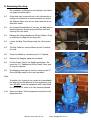
1
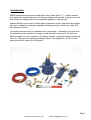
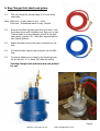
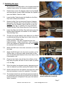
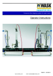
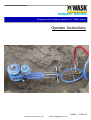
HYDRANT WIZARD
Temporary flow stopping system for 3“ Water mains
Operator Instructions
ISSUE 7 - 27 Mar 09
Website: www.wask-uk.com
email: [email protected]
INDEX
TITLE
Page No.
Introduction
1.
1.
General Notes
2.
2.
Mounting the saddle
3.
3.
Drilling the pipe
4.
4.
Preparing the Bagging Head
5.
5.
Preparing the Pressurisation Unit
6.
7.
Isolating the pipe
7.
8.
Removing the stop
8.
9.
Fig 1. Schematic Layout
9.
Website: www.wask-uk.com
email: [email protected]
Introduction
WASK Hydrant Wizard has been developed to stop water flow in 3“ ~ 80mm nominal
bore pipes with minimal disruption. It has been designed to provide an easy to use, low
cost solution to stopping flow in an operational pipeline or hydrant riser.
Hydrant Wizard can be used to isolate piping systems for repair, alterations and renovation and is suitable for most pipe materials including cast iron, ductile iron, steel, PVC,
and Asbestos-Cement.
The system involves using an inflatable SARCO Hydra Bag™ inserted into the pipe with
the specialist launch equipment through a small diameter access hole. The bag is inflated by means of water pressure in the mains, through a specially designed pressurisation unit The system comprises lightweight easy to use equipment, for up to 6 bar
pressure and flow rates up to 4 litres/sec.
Page 1
Website: www.wask-uk.com
email: [email protected]
1. General notes
A. DO NOT OPERATE THIS EQUIPMENT UNLESS YOU HAVE BEEN TRAINED IN ITS USE AN HOLD
THE RELEVANT TRAINING CERTIFICATE ISSUED BY WASK
B. IF ANY OF THESE INSTRUCTIONS CONFLICT WITH THOSE OF YOUR EMPLOYER, YOUR EMPLOYERS INSTRUCTIONS MUST BE OBEYED.
C. ALWAYS CHECK THAT ALL PARTS ARE AVAILABLE AND IN GOOD WORKING ORDER BEFORE
COMMENCING WORK.
1.1
The flow stop equipment shall comply with the latest design and all the associated equipment
and fittings used during a stopping off operation shall be in sound working order.
1.2
It is important to note that to stop off the pipe at an operating pressure in excess of 6 bar or
flow rate in excess of 4 litres per second and where pressure or flow reduction is not practicable, it will be necessary to use an alternative stopping off system in accordance with approved codes of practice and manufacturers recommendations.
1.3
Before a programmed stopping off operation is undertaken, the operating pressure of the
main should be reduced to the lowest level at which adequate supplies can be maintained.
1.4
A work programme shall be prepared and should include schedules of all necessary safety
and operational equipment and of all operational procedures. This programme should include
contingency plans for the possibility of bag failure and the availability and operability of upstream and downstream line valves in case mains shut down is required.
1.5
Bag inflation pressures are automatically regulated by the Pressurisation Unit supplied with
the kit. Use of other means to inflate the stopper bag may result in over inflation and possible
failure of the bag and is not recommended by WASK.
1.6
Bags may be reused providing they are in sound condition and 8 hours exposure in water
main is not exceeded.
Page 2
Website: www.wask-uk.com
email: [email protected]
2. Mounting the saddle
2.1
Clean an area approximately 75mm (3”) wide all
around the pipe of all loose paint/tape/dirt/rust and
inspect for large corrosion defects or markings which
will impair sealing of the saddle/clamp.
It may be necessary to grind off any markings which
lie directly under the rubber seal.
2.2
Attach the 1 1/2“ x 3” Saddle & Strap assembly to
the Riser or neck of Hydrant Tee. Note the strap can
be pre-formed around the pipe to aid assembly and
should be fitted with plastic cover against the pipe.
2.3
Lubricate the bolts, fit to strap and then tighten progressively by turning the bolts alternatively until a
torque of 35 Nm (25 ft.lbs) is reached on both fasteners.
2.4
Ensure the 1½“ spatula can be inserted and removed easily from the slot in the body, The blade
can be lubricated with Silicon Oil (WRAS listed or Wrc
approved) to aid operation.
2.5
Pressure test if required using Pressure Gauge & Test
Head assembly supplied with the kit. Follow your
normal test practice for this, the saddle should be
tested hydraulically to at least the operating mains
pressure.
Note :Alternatively the saddle may be pneumatically tested
at between 1.0 ~ 2.0 Bar, the pressure gauge can be
monitored for leaks or the saddle may be soap solution tested.
2.6
Depressurise and remove test assembly and gauge.
2.7
Check that the closure cap fits the saddle and can be
screwed home, then remove and store in a safe
place.
2.8
The pipe is now ready to drill.
Page 3
Website: www.wask-uk.com
email: [email protected]
3. Drilling the pipe
3.1
Fit the 35mm diameter Hole Saw to the drilling spindle. When cutting metallic pipes ensure the Swarf
Magnet is present inside the Hole Saw.
Note :Steel/Cast Iron/Ductile Iron - Use a Constant Pitch
Bi-Metallic Hole Saw
PVC - Use a Carbide Tipped Hole Saw
Asbestos Cement - Use a Carbide Grit or Diamond
Edge Hole Saw
3.2
Fit the Drilling Spindle into the Drilling Head. Disinfect
and then mount the Drilling Head onto the Saddle
and hand tighten to seal.
3.3
Locate and engage the ¾” square drive spanner onto
the drilling spindle and lower the spindle until the
Hole Saw touches the crown of the service pipe.
Lightly press on the top of the spanner whilst starting
the drilling process, this will centre the cutter.
3.4
Lift the Bridle and engage the Feed Screw. Continue
to drill using a light feed force to carry out the drilling
process. Do not try to force the saw through the cut
as this could lead to breakage of the Cutter teeth.
3.5
As the Cutter begins to break through into the bore
of the pipe reduce the pressure on Feed Screw. This
will help reduce the size of burr produced by cutting.
3.6
Once the cut is complete, remove the Ratchet Spanner, the Drilling Spindle can then be lifted up until it
reaches the stop in the Drilling Head.
3.7
Close the Saddle by inserting the 1½” Spatula.
3.8
Remove the Drilling Head and check that the coupon
is still in the Hole Saw.
3.9
Remove the Drilling Spindle from the Drilling Head,
remove the coupon and swarf from the Hole Saw,
check Magnet is present, clean and return to tool
box. Clear any swarf which may have fallen into the
Saddle threads.
3.10
Fit the Pressure Gauge head to the Saddle and take a
Mains pressure reading. Remove Pressure Gauge.
Record this reading for future use.
Page 4
Website: www.wask-uk.com
email: [email protected]
4. Preparing the bag head
NOTE.
If this Stopper Bag has been used before, inflate and
inspect for damage before installing, note limitations
on reusing bags. Check both O-rings are present in
bag connector.
4.1
Extend the Bag Tube until the end can be seen, remove the 3” Shoe using the 4mm Hex key and then
extend the Inflation Tube until the connector is visible.
4.2
Fit the Bag to the Connector on the Inflation Tube.
Tighten the Bag using the 19mm Spanner provided
until a firm resistance is felt. A seal is made on the
O-rings, so do not over tighten as this will not improve the seal and will only damage the equipment.
4.3
Lubricate the Bag lightly with Silicon Oil applied by
aerosol (WFBS listed or WRc Approved) and draw the
Bag into the Bag Tube.
4.4
Refit the 3” Shoe to the Bag Tube until hand tight
using the 4mm Hex key. It is not necessary to tighten
this any further.
4.5
Spray some Silicon Oil lubricant into the opening of
the Bag Tube to assist the launch of the Bag.
4.6
Test launch the Bag. Align the curvature of the bag
and ensure the “Sniffer” pipe will be on top when
launched then align the Inflation Tube Direction Indicator to the Bag Tube Indicator, tighten using the
5mm Hex key.
4.7
Withdraw the bag into the Bag Tube.
4.8
The Bagging Head is now ready for use.
Page 5
Website: www.wask-uk.com
email: [email protected]
5. Bag Charger Unit check and prime.
5.1
The unit should be stored empty if it is not being
used daily.
Note. Blue hose – Fresh water to unit – Input
Red hose – Disinfected water to bag - Output
5.2
Remove the Filler Cap and open the vent valve. Push
the piston down until it bottoms out. Drop one or two
Chloros tables in to the chamber and fill to top with
clean water, approx 1.5 L. Refit filler cap and tighten
with 36mm Spanner.
5.3
Attach the Blue hose to the upper connector on the
unit.
5.4
Connect the Red hose to the connector on the Filler
Cap.
5.5
Connect a waste hose or tube to the barbed connector on the unit, ¼“ or 6mm PVC tube will suffice.
The Bag Charger unit and hoses are now primed
for use.
Page 6
Website: www.wask-uk.com
email: [email protected]
7. Isolating the pipe
Any jammed or corroded bolts on the Hydrant should be
replaced singly before the stopping operation begins.
7.1
Disinfect then mount the Bagging Head onto the Saddle
and hand tighten to seal. Slowly withdraw the Spatula to
open the Saddle. Check for leaks.
7.2
Lower the Bag Tube through the Saddle into the Riser
Pipe until it touches the bottom.
7.3
Rotate the Bag Tube so that both Direction Indicator
faces down the Riser Pipe in the direction of the Main –
DO NOT turn the Inflation Tube to do this or you risk
damaging the bag or breaking the bag connection.
Tighten the Bag Tube Clamp using the 12mm spanner
7.4
Launch the Bag into the Riser Pipe and secure using the
Holding Bands between the handles on the Inflation
Tube and Bag Tube.
7.5
The bag can now be tested in two steps prior to inflation
by alternatively fitting the Bag Vent to each of the connectors on the Inflation tube.
Lower connector - No water should flow from this.
Upper Connector - Water should flow - this is important
as no flow indicates a blockage in the bag which MUST
be resolved before continuing.
7.6
Attach the RED hose to the lower connector on the Inflation tube.
7.7
Attach the BLUE hose to the top most connector on the
Inflation tube. At this point water should start to flow
from the flexible tube attached to the Vent Valve on the
Pressurisation unit.
7.8
Close the Vent Valve, this will start the inflation of the
bag. Note the piston will start to rise as water is pushed
in to the Bag.
7.9
When the piston has stopped moving, depressurise and
vent the Hydrant by slowly opening the Hydrant Valve.
7.10
Monitor the flow from the Hydrant and ensure the piston
does not continue to move for a period of 5 minutes.
7.11
The Hydrant should now be fully depressurised and water should stop issuing with any force from the Hydrant,
a small trickle can be expected. Fully open the Hydrant
Valve if possible
The Hydrant is now isolated and
may be safely be removed.
Page 7
Website: www.wask-uk.com
email: [email protected]
8. Removing the stop.
On completion of fitting the new Hydrant, the following steps should be taken.
8.1
A leak test may be carried out on the Hydrant by allowing it to pressurise to mains pressure by closing
the Hydrant Valve once air has been bled and it has
filled with water
8.2
On successful completion of the test, the Bag may be
depressurised by disconnecting the Blue hose and
opening the vent valve.
8.3
Release the holding bands and lift the Inflation Tube
to withdraw the Bag into the bag tube.
8.4
Loosen the Bag Tube Clamp using the 12mm spanner.
8.5
The Bag Tube can now be lifted up until it reaches
it’s stop.
8.6
Close the Saddle by reinserting the 1½“ Spatula.
8.7
Remove the Bagging Head and set aside.
8.8
Fit the Closure Cap to the Saddle and tighten. Remove the 1½” Spatula and fit the Plastic Cover and
O-rings as required.
8.9
The Bagging Head can be reset by removing the 3”
Shoe and Bag ready for the next operation.
Note.
If another job is going to be carried out immediately
the bag can be left attached to the equipment, however DO NOT store the equipment with a bag fitted
for more than 24 hours or it may become jammed.
8.10
Clean and return all the equipment and tools to the
Equipment Box.
Page 8
Website: www.wask-uk.com
email: [email protected]
Fig 1. Hydrant Wizard schematic layout
Website: www.wask-uk.com
email: [email protected]
Page 9
Website: www.wask-uk.com
email: [email protected]