1
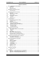
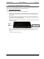
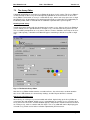
™ B20 User Manual Product Number BB-20 Instructions for Use Version : 1.5 IT IS IMPORTANT TO READ THIS MANUAL BEFORE USING THE B20 Bee Robotics Ltd. B20 - User Manual Version 1.5 TABLE OF CONTENTS 1 B20 - OVERVIEW OF INSTRUMENT ...................................................................................... 3 1.1 Introduction........................................................................................................................ 3 1.2 B20 Layout ........................................................................................................................ 4 1.3 B20 Specifications............................................................................................................. 5 2 WARNINGS AND PRECAUTIONS .......................................................................................... 6 2.1 Limited Warranty ............................................................................................................... 6 3 UNPACKING AND INSTALLATION ......................................................................................... 7 3.1 Unpacking ......................................................................................................................... 7 3.2 Environmental conditions .................................................................................................. 7 3.2.1 Bench Space .................................................................................................................. 7 3.3 Disconnection guidelines .................................................................................................. 8 3.3.1 Ventilation ....................................................................................................................... 8 3.3.2 General ........................................................................................................................... 8 3.4 Electrical Power................................................................................................................. 8 4 USING THE B20 ....................................................................................................................... 9 4.1 Pump Setup and Reagent Tubing..................................................................................... 9 4.2 Installation Check ............................................................................................................ 10 4.3 Initial Run ........................................................................................................................ 10 4.4 Possible Warning Alarms ................................................................................................ 12 4.4.1 Attaining Set Point Temperature: ................................................................................. 12 4.4.2 Deviation from Set Point Temperature: ........................................................................ 12 4.5 Cleaning Instructions....................................................................................................... 12 4.5.1 Cleaning the B20 .......................................................................................................... 12 4.5.2 Cleaning of B20 Trays .................................................................................................. 12 5 TROUBLESHOOTING GUIDE ............................................................................................... 13 5.1 Basic Troubleshooting – Visual Inspection ..................................................................... 13 5.1.1 Mechanics..................................................................................................................... 13 5.1.2 Fluidics.......................................................................................................................... 13 5.2 Initialisation...................................................................................................................... 14 5.3 Basic Troubleshooting Flowchart .................................................................................... 15 5.4 Running The Instrument With Water............................................................................... 16 5.5 Instrument Failure – Further Assistance ......................................................................... 17 5.6 Questions To Ask When A Fault Is Reported ................................................................. 17 6 PREVENTATIVE MAINTENANCE SCHEDULE..................................................................... 18 6.1 Three Monthly Maintenance............................................................................................ 18 6.2 Six Monthly & Yearly Maintenance ................................................................................. 19 7 B20 PROGRAMMABLE SOFTWARE .................................................................................... 20 7.1 Introduction...................................................................................................................... 20 7.2 Software Installation ........................................................................................................ 20 7.3 The Assay Editor ............................................................................................................. 21 7.4 Assay Editing................................................................................................................... 22 7.4.1 Uploading an assay ...................................................................................................... 25 7.5 Assay Settings................................................................................................................. 26 7.6 Instrument Settings ......................................................................................................... 29 7.7 General............................................................................................................................ 31 7.8 Glossary of Terms ........................................................................................................... 32 8 TECHNICAL SUPPORT ......................................................................................................... 33 8.1 Spare Parts List............................................................................................................... 33 9 APPENDIX .............................................................................................................................. 34 9.1 Appendix I - EU DECLARATION OF CONFORMITY ..................................................... 34 9.2 Appendix II – B20 INSTALLATION CHECKLIST............................................................ 35 9.3 Appendix III – DECONTAMINATION CERTIFICATE ..................................................... 37 Bee Robotics July 2009 Page 2 Bee Robotics Ltd. B20 - User Manual Version 1.5 B20™ Please read this manual carefully before using the B20 and make it accessible to all users. Failure to comply with the instructions in this manual will void the manufacturer’s warranty and may pose a risk to the user. Ensure all users are conversant with the instrument – contact Bee Robotics for any further instrument or training requirements if in any doubt before using the instrument Consult User Manual where symbol (left) is seen on the instrument 1 B20 - OVERVIEW OF INSTRUMENT 1.1 Introduction The B20 is designed for use with reverse line blot strip assay, and provides full automation for the washing and hybridisation steps. The strips are placed into the 20 well tray held on a platform within the B20 (see Figures 2 & 3, page 4) and the whole detection assay is performed within the 20 well tray. Fixed to the underside of the platform is a unique heating mat, which gives uniform and precise temperature control during the assay. A moving arm both aspirates and dispenses reagents simultaneously across the tray. The minimum number of samples that can be processed during a run is 2 and the maximum is 20. The B20 is fully programmable from an user-friendly windows based software, where the operator can custom build their assay protocols. Once the assay has been programmed using the software, the assay parameters can be uploaded from the PC to run from the instrument using the integral keypad. Up to 12 different assay protocols can be stored and selected for use via the integral keypad. A powerful cross flow fan can be selected to help cool the tray after a heating step. The B20 also incorporates two built in pre-heaters for warming up reagents prior to being dispensed into the tray, and a solenoid valve for re-directing waste. All these features can be included into any assay using the programmable software. Bee Robotics July 2009 Page 3 Bee Robotics Ltd. 1.2 B20 - User Manual Version 1.5 B20 Layout Fig. 1: Front view of B20 Instrument Integral Fan Robotic arm with dispensing and aspirating needles Display and Keypad 20 Well tray Watlow Controller One of seven Peristaltic Pumps Two reagent preheaters Position for reagent containers Fig. 2: Rear ¾ view of B20 Instrument Serial Label Mains input Filter Bee Robotics July 2009 RS232 Socket Page 4 Bee Robotics Ltd. 1.3 B20 - User Manual Version 1.5 B20 Specifications Display unit LCD with 2 rows of 16 digits Keyboard 5 membrane covered switches Number of dispensing heads 6 Cross flow Fan 24v DC Reagent Pre-Heaters 2 x 24v DC 80ºC Thermostat Control / 92ºC thermal fuse Optional Reagent Save Feature Reversible Pumps Peristaltic Pumps 7 on board. Power ON Indicator Green LED Capacity of reagent containers 1*500ml, 2*250ml, 4*125ml (may differ slightly) Computer interface RS232 Test capacity Minimum 2 samples; maximum 20 samples Instrument control Interactive keypad Temperature setting Ambient to 55 C Temperature Control Programmable Watlow Controller Temperature Sensor PT100 Class A Volume of reagent dispensed 0.25-4.0 ml Dispensing accuracy ± 10% o Environmental o Operation 15 - 30 C Operating Temperature Range 18 - 24 C Storage Altitude -10 to 70 C o Maximum relative humidity = 80% for temperature up to 31 C o decreasing linearly to 50% relative humidity at 40 C Up to 2000m Over voltage category II Method of Disposal Hazardous waste Usage Commercial Pollution Degree 2 Relative humidity o o Power Supply Fuses Non Operator Internal Fuses Consumption 100 - 120V (U.S.) Mains supply voltage fluctuations within ± 10% of normal voltage 220 – 240V (European) T rating 10 amps @ 110volts T rating 5 amps @ 220- 240Volts Main Controller Board – J25 to J30: 1A Main Controller Board – J31 & J32: 2.5A Power Supply Unit – AC 100-250V 3.2A 50/60 Hz o Heater Mat Thermal Fuse – 92 C 10 amps @ 110 volts 4.7 amps @ 220 - 240 volts Physical Dimensions 470mm (wide), 480mm (deep) 500mm (height) Weight 40kg Bee Robotics July 2009 Page 5 Bee Robotics Ltd. B20 - User Manual Version 1.5 2 WARNINGS AND PRECAUTIONS : Please observe the following caution labels located on the B20 Fig.3: Warning Labels on B20 2.1 Limited Warranty The product is warranted for 12 months from date of shipment to the original purchaser only. Claims for merchandise damaged in transit must be submitted to the carrier. This warranty shall not apply to any product, which shall have been altered outside Bee Robotics, nor shall it apply to any, which have been subjected to misuse or mishandling. ALL OTHER WARRANTIES, EXPRESSED, IMPLIED OR STATUTORY, ARE HEREBY SPECIFICALLY EXCLUDED, INCLUDING BUT NOT LIMITED TO WARRANTIES OF MERCHANTABILITY OR FITNESS FOR A PARTICULAR PURPOSE. Bee Robotics Ltd.’s maximum liability is limited in all events to the price of the products sold by Bee Robotics. IN NO EVENT SHALL BEE ROBOTICS BE LIABLE FOR ANY SPECIAL, INCIDENTAL OR CONSEQUENTIAL DAMAGES. This product may not be repackaged, reformulated or resold in any form without the written consent of Bee Robotics Ltd. Bee Robotics Ltd. reserves the right to make technical improvements to TM TM the B20 and B20 documentation without prior notice as part of a continuous programme of product development. As part of the WEEE EU directives, this instrument should be returned to the manufacturer for dismantling at the end of its life TRADEMARKS AND PATENTS: Trademarks: TM B20 is a trademark of Bee Robotics Ltd, UK. ® ® Tygon and PHARMED are registered trademarks of Norton Performance Plastics Corp. Intellectual Property Rights The B20 and any derivatives of this product remains the Intellectual Property of Bee Robotics Ltd. Bee Robotics July 2009 Page 6 Bee Robotics Ltd. B20 - User Manual Version 1.5 3 UNPACKING AND INSTALLATION 3.1 Unpacking CAUTION: HEAVY INSTRUMENT AT LEAST two people are required to move the carton, to unpack, and to lift the instrument from the carton and position on the bench. The instrument weighs 28kg and the whole unopened carton may weigh as much as 75kg 1. Visually inspect the container for transit damage. 2. Place the carton in an upright position to open. 3. Unpacking: - the instrument is packed in a re-usable container, which may be collapsed for storage. It is recommended that appropriate gloves be worn for unpacking; some components of the container may have sharp edges. Remove the outer straps and lift off the main cover. Lift the outer shell upwards and place to one side. Lift off the protective foil and carefully lift the instrument off the base of the box and place to one side. Two people are required to lift the instrument off the base, one positioned at the front of the instrument, and one person positioned at the back of the instrument. At the same time, lift one side of the instrument and remove the foam side and gently rest the instrument down, repeat this procedure for the other side of the instrument. Remove the foam wedge protecting the viewing window and lift the instrument onto an appropriate bench. The outer shell can be collapsed flat and placed onto the base of the packaging and the lid replaced over it. 4. Inspect for any obvious signs of transit damage. Report any damage immediately to your local representative. 5. Check that the serial number on the instrument and the delivery note are the same. 6. Check the remainder of the contents against the delivery note. See the Installation Checklist at rear of manual for details of accessories that should be present. 7. Store packing materials until you are completely satisfied that the instrument was delivered safely and that it is performing to specification. 3.2 3.2.1 Environmental conditions Bench Space At least 500 mm x 500 mm space is required at bench level. The lid swings upwards so that, when open, the height is 1 metre from the instrument base to the top of the lid. The instrument should be placed on a bench at least 15cm away from the wall. Appropriate power as described in the specification must be available within 1 metre. It is preferable to locate the instrument near a suitable laboratory waste outlet. Alternately, position a waste container of at least 4-litre capacity in close proximity to the instrument. One of the waste tubes is gravity fed, so ensure the waste container is below the level of the machine. Ensure waste pipes are not trapped under the instrument. Bee Robotics July 2009 Page 7 Bee Robotics Ltd. 3.3 B20 - User Manual Version 1.5 Disconnection guidelines The mains switch and mains lead connection is to the bottom right hand side as viewed from the front. The instrument should be 120mm from any side wall so that there is ample clearance for the mains connector, and to facilitate disconnection in an emergency. Do not place the instrument too close to any object that might impair emergency disconnection in an emergency, particularly any object to the right or rear of the instrument. 3.3.1 Ventilation Do not place the instrument in line with a direct draft such as an air vent. Otherwise there are no specific ventilation requirements for the instrument. Allow a space of 100mm between the instrument and any wall or other instruments. 3.3.2 General The B20 is intended for indoor use only and should not be subjected to unduly large variations in temperature and humidity. This instrument was designed for use in a typical laboratory environment (see 1.3 Specifications). Keep free of dust, harsh solvents and acidic vapours. Vibration and harsh sunlight must be avoided to ensure correct results. The B20 should always be placed on a flat stable surface. Storage conditions: from 5ºC to 50ºC NOTES - 3.4 If the instrument is to be relocated with the laboratory, it is important to follow the Unpacking and installation procedures outlined in the above paragraphs. Electrical Power It is essential that U.S. Models are used in the U.S. and E.U. models are used in Europe. Check the information on the side of the instrument carefully. Leave to stand for 3 hours before applying power to avoid problems that might arise from condensation. In an emergency immediately turn the power off and unplug from power source. REPLACE FUSES WITH EXACTLY THE SAME TYPE AND RATING. Bee Robotics July 2009 Page 8 Bee Robotics Ltd. B20 - User Manual Version 1.5 4 USING THE B20 4.1 Pump Setup and Reagent Tubing TM Tygon tubing is used throughout the instrument. The tubing fittings are luer lock type. TM The B20 has 7 pumps. The material in the peristaltic pumps is Pharmed . The Pump Layout is as shown: P1 P2 P3 ASP P5 P6 P4 Fig. 4: Pump Layout of B20 ASP is the aspirating pump. All the other pumps are reagent dispensing pumps. There are 6 pairs of dispensing needles in the instrument arm. Pair 1 is positioned at the front of the arm. The instrument-dispensing head is organised as follows: Aspirating Needles Pair 6 Pair 5 Fig. 5: Drawing of dispensing layout Pair 4 Pair 3 Pair 2 Pair 1 Each pump has the following typical function: Pump Number Needle Set Dispensed Through ASP Aspirates through aspirating needles Pump 1 Dispensed through pair 6 Pump 2 Dispensed through pair 2 Pump 3 Dispensed through pair 3 Pump 4 Dispensed through pair 4 Pump 5 Dispensed through pair 5 Pump 6 Dispensed through pair 1 Bee Robotics July 2009 Page 9 Bee Robotics Ltd. B20 - User Manual 4.2 Installation Check a. b. c. Switch instrument ON The instrument will initialise. The initialisation sequence of events are: i ii iii iv v Version 1.5 The display will indicate “BeeBlot Ready Press Start” The aspirating needles move up to their HOME position. The arm will move left to its HOME position. The tray mechanism will move into its HOME position. The green LED at the front of the instrument will come on Fig. 6: B20 Keypad & Display 4.3 Initial Run Before using the instrument for analysing samples it is recommended that the following series of instrument checks be undertaken: Priming, dispensing and aspiration of wash solution - Ensure that the power to the instrument is OFF. - Ensure that the waste tube is routed either into a suitable sink or into a suitable 4 litre empty container. One of the waste tubes is gravity fed. Ensure the waste container is BELOW THE LEVEL OF THE MACHINE AND THE WASTE TUBES ARE NOT TRAPPED UNDER FEET. - Switch Power ON, and ensure that the instrument initialises properly (refer to Installation Check above) - The B20 will have one or more assays preloaded when new. It is recommended that a dummy run is set up with water, to ensure that the selected assay performs the steps as required. (Alternatively, it is possible to create an assay by using the programmable software provided with the instrument. It is necessary to upload the assay into the instrument from your PC, allowing the operator to run the instrument from the integral keypad. Refer to section 7 of this manual for instructions on creating and uploading assays.) - Fill all reagent bottles with de-ionised water. Note: it is important not to run the instrument without liquids. Serious damage to the instrument may occur. - Place the supplied tray on the table of the instrument. TRAY ORIENTATION: The tray has been designed in such a way that it can be positioned in one direction only. The operator must position the sensor into the tray as prompted by the keypad display prior to starting the assay: Fig. 7: Temperature Sensor - Always position sensor so that it is in the fully ‘down’ position prior to starting an assay. The sensor must be treated with care at all times. Press Start on the Keypad, select the required Assay, and follow the keypad commands. Bee Robotics July 2009 Page 10 Bee Robotics Ltd. B20 - User Manual Version 1.5 - Depending on the assay selected, there may be an option to select a Cleaning Cycle A/B. Press Quit on these steps. - Select the number of samples to be 2, press Start, and follow the keypad commands until the run commences. Following the first dispensing phase, the tray should start to rock & the Watlow Controller will come on, depending on the assay program. Ensure that the temperature starts to rise Press Quit to switch off the temperature controller, and ensure that the display indicates ‘Heater Error’, and that the controller has switched off. At this point it is necessary to press ‘Start’ and the operator will then be given the choice of continuing with the assay without the temperature on, or to abort the assay. Fig. 8: Watlow Controller - For non-heated steps within the assay, it is necessary to press the right arrow key on the keypad in order to quit that particular step and move on to the next step within the assay. PLEASE NOTE THAT IF THE ‘QUIT’ KEY IS DEPRESSED DURING NON-HEATED STEPS, THEN THE ASSAY WILL BE ABORTED. - If no problems have been encountered, the instrument may now be used for analysis. Complete and sign the B20 installation checklist (Refer to Appendix II), and return it to your local representative. - If you follow this procedure, you will be able to observe whether the Pre-heaters, Fan, Watlow Controller, and any other parameter selected for the assay, are activated at the appropriate times during the assay. Preheater A is the furthest out (shown on the LEFT here) Fig. 9: Reagent Preheaters Preheater B is nearest to the pumps (shown on the RIGHT here) If no problems are encountered during the water run, the instrument can now be used to run an assay. Bee Robotics July 2009 Page 11 Bee Robotics Ltd. 4.4 B20 - User Manual Version 1.5 Possible Warning Alarms The B20 has two built in alarm systems, with the following features: 4.4.1 Attaining Set Point Temperature: If it takes more than 20 minutes for the temperature controller to reach the specified temperature, than an audible alarm will be heard, and the display will indicate heater error. The operator must press the ‘Start’ key on the keypad to silence the alarm. The operator will then have the option to continue with the assay without the function of the heater, or press the ‘Quit’ key to abort the assay. 4.4.2 Deviation from Set Point Temperature: Once the set point temperature has been reached, and audible alarm will be activated if the temperature deviates more than 1.5 degrees from the specified set point temperature. The operator must press the ‘Stop’ key on the keypad to silence the alarm. The operator will then have the option to continue with the assay without the function of the heater, or press the ‘Quit’ key to abort the assay. 4.5 Cleaning Instructions 4.5.1 Cleaning the B20 It is recommended that on a monthly basis, that the outside of the instrument is cleaned using anti-static foam applied sparingly to the instruments outside panel. The operator should switch off the instrument, close the lid, and apply the foam to one panel at a time. A dry lint free cloth should be used to wipe off the foam. Particular attention should be made not to spray the foam into the instrument. 4.5.2 Cleaning of B20 Trays NOTE: DO NOT USE DETERGENTS. Residue left from some detergents can affect colour development of strips and increase background. If trays are not washed immediately after use, fill trays with water until they can be washed. Note: These steps are performed by hand and not in the B20. The B20 tray should be cleaned as follows: - Add 5ml of an appropriate washing solution to each well used of the tray. Carefully rock the typing tray back and forth for 30-60 seconds to dissolve any residue. Allow to stand for 5 minutes. Pour off the washing solution well into sink with running water. Repeat steps 1 and 2. Rinse each well in the tray thoroughly with de-ionised water. Allow tray to air dry. The tray is now ready for re-use. Bee Robotics July 2009 Page 12 Bee Robotics Ltd. B20 - User Manual Version 1.5 5 TROUBLESHOOTING GUIDE 5.1 Basic Troubleshooting – Visual Inspection A good visual inspection of the instrument prior to switching it on can sometimes reveal problems or potential problems. Performing these simple checks will help determine the condition of the instrument. 5.1.1 • Mechanics Open the lid and ensure that the aspirating probes on the arm move upwards and downwards freely by hand. Leave the aspirating probes in the up position and move the arm from right to left by hand ensuring that the arm moves freely. If any resistance or obstructions are encountered during these tests, the problem will be a mechanical one. Aspirating Probes Fig. 10: B20 Arm Dispensing Arm • For the aspirating probes ensure that the two screws holding the linear slide in place are intact and secure. Ensure that the stepper motor is secure, and that the HOME sensor tag on the linear slide moves freely in and out of the opto sensor on the arm’s circuit board. • For the arm ensure that the screws holding the linear slide are secure, and that the belt is taught. • For the rocking mechanism ensure that tray support plate moves freely. 5.1.2 • Fluidics Check integrity of tubing from the pumps to the bottles. Pay particular attention to the tubing connectors at the top of the bottle lids. Any damage to the connectors will result in poor or no dispensing. If the tubing has become blocked or partially blocked, this will also result in poor or no dispensing. Tubing Connectors Fig. 11: Bottles & Tubing Bee Robotics July 2009 Page 13 Bee Robotics Ltd. B20 - User Manual Version 1.5 • Ensure that the waste tubing from the aspirating pump, and from the waste wash trough is intact and not blocked in any way. Ensure that the peristaltic pump clips are correctly positioned. If the aspirating tubing is blocked, the tray will not empty and will result in a spillage, and if the waste tubing is blocked the wash trough may not empty. • Ensure that the tray locates properly into the clamps on the tray support plate. Fig. 12: B20 Tray & Tray Clamps • If no problems are encountered during visual inspection, the instrument can be switched on. If problems are encountered during visual inspection, these must be rectified prior to switching the instrument on; otherwise further damage may be done to the instrument. 5.2 Initialisation The instrument will always perform the same initialisation routine when it is switched on. Prior to switching on the instrument move the arm to half way across it’s travel, and move the aspirating probes half way down. When the instrument is switched on, the sequence of events should be as follows: 1. 2. 3. 4. 5. The green LED at the front of the instrument should be on. The display will indicate ‘BeeBlot Ready Press Start’ The aspirating probes should move upwards to it’s HOME position The arm will move left to it’s HOME position The tray rocking mechanism will move to it’s HOME position If the instrument fails to perform any or all of these tasks, then there is a fault, which needs to be rectified. • If the instrument fails to perform sequence 1 described above, then either there is a fault with the 24V power supply, or the mains fuses have blown. • If the instrument fails to perform sequence 2 described above, and there is nothing or random characters on the display then either there is a fault with the associated cable, the circuit board, or the display itself. • If the instrument fails to perform step 3 described above, then either there is a fault with the motor, the associated cable, the sensor or with the circuit board. • If the instrument fails to perform step 4 described above, then either there is a fault with the motor, the associated cable, the sensor or with the circuit board. • If the instrument fails to perform step 5 described above, then either there is a fault with the motor, the associated cable, the sensor or with the circuit board. If however the instrument initialises correctly, then fill the reagent bottles with water and run the instrument. Bee Robotics July 2009 Page 14 Bee Robotics Ltd. 5.3 B20 - User Manual Version 1.5 Basic Troubleshooting Flowchart If you are experiencing problems with your instrument, it is worth spending a few minutes performing a visual inspection to check for any obvious signs of damage. The instrument will always perform the same sequence of events each time it is switched on. The aspirating probes will move upwards, followed by the dispensing arm moving left to the “HOME” position, followed by the tray support table rocking a couple of times. Follow the guide below to help determine where the problem might lie: Fig. 13: Troubleshooting Flowchart Does the instrument initialise correctly? NO YES NO Does the instrument prime correctly? NO Do the aspirating probes move upwards? Is the Green light Power indicator ON? If not check mains fuses, and or mains cable. Replace fuses with correct rating and type if found to be blown. Determine which reagent does not prime. If the corresponding pump is turning, then there is a blockage in that particular line. Check all luer connectors for damage YES YES Switch Off. Move mechanism up and down by hand. It should be free to move without any obstructions. If you experience difficulties, there may be a mechanical problem. Ensure that the aspirating mechanism is not loose. NO Does the tray empty correctly? Does the arm move to its Home position? NO YES Switch Off. Ensure the aspirating probes are in the up position and move the arm right to left by hand. It should be free to move without any obstructions. If you experience difficulties, ensure the arm is not loose, and that there are no loose screws underneath the linear slide. Does the tray support table rock? NO Ensure that the aspirating tubing is attached to the aspirating probes. Ensure that the aspirating pump is turning. Ensure that the waste tubing is not obstructed in any way YES YES Bee Robotics July 2009 Switch Off. Ensure that the rocking table is not loose. Turn the rocking mechanism by hand to ensure that the table moves up and down. Page 15 Bee Robotics Ltd. 5.4 B20 - User Manual Version 1.5 Running The Instrument With Water Each reagent has its own dedicated pump, which means it’s straightforward to determine which if any of the dispensing lines are blocked. P1 P2 P3 ASP P5 P6 P4 Fig. 14: Pump Layout of B20 Aspirating Needles Pair 6 Pair 5 Fig. 15: Drawing of dispensing layout Pair 4 Pair 3 Pair 2 Pair 1 Perform the cleaning cycle A or B to ensure that the water flows through the appropriate dispensing needles under the arm. Observing the cleaning cycle will ensure that each reagent tubing line and the corresponding pump is functioning correctly. If nothing is dispensed through the dispensing needles and the corresponding pump is turning then there is a blockage in that particular reagent line, or the fluid lines have been assembled incorrectly during servicing. If the corresponding pump does not turn then the pump or circuit board is faulty. (An engineer would plug the pump that doesn’t turn into another position on the circuit board, and go through the priming sequence again. If the pump fails to turn, then the problem is with the pump. If the pump now turns in this new position, then the problem is with the circuit board.) If the cleaning cycle is performed correctly, then start an assay and allow the instrument to dispense the first reagent into the tray, then allow the arm to return to its HOME position. Take a look at the dispensing needles underneath the arm. No water should be flowing through or continuously dripping at this stage. If water is present then there is a leak in the corresponding tubing, or the pump clamp has not clipped into place properly. Press quit on the keypad, and observe the aspirating needles, ensuring that the tray wells are emptying. When the next reagent is added, you may see some drops forming after the pump has stopped turning, this is normal and does not indicate a fault, unless there is a continuous flow of drops, which would have been observed when the arm was in the HOME position. Bee Robotics July 2009 Page 16 Bee Robotics Ltd. 5.5 B20 - User Manual Version 1.5 Instrument Failure – Further Assistance If the instrument fails it is often useful to repeat the B20 run with water to see if the fault occurs again. To do so, fill all reagent bottles with DI water & proceed with the assay as normal. Do not add strips to the tray. Check that each step of the assay is being performed correctly. 5.6 Questions To Ask When A Fault Is Reported 1. What is the instrument’s Serial Number? This information is required to determine whether the instrument is under warranty or not, and if for some reason we need to refer to the instrument’s history file. 2. Does the instrument initialise properly? Yes or No. Yes – then the problem is likely to be a heating problem or a fluidics problem. Ask the operator to run the instrument with water, and check the priming sequence to ensure that there are no blockages. If there are no blockages, the operator should check that the aspirating probes are emptying the tray; if the tray is not emptying the tray will overfill. No – then the problem is likely to be mechanical or electronic. Ask the operator to determine exactly at what stage the initialisation fails in order to diagnose the problem. Bee Robotics July 2009 Page 17 Bee Robotics Ltd. B20 - User Manual Version 1.5 6 PREVENTATIVE MAINTENANCE SCHEDULE In order to keep the B20 in good working order, it is recommended that the following steps be followed as part of a regular field preventative maintenance program. 6.1 Three Monthly Maintenance The following checks must be carried out on a three monthly basis: 1. Check that the aspirating tubing is free and unobstructed. This can be checked visually, and by running the instrument with water and ensuring that the wash trough empties during aspiration. 2. Check that the dispensing needles underneath the arm are dispensing correctly during priming. If any of the needles fail to dispense, ensure that the corresponding pump is turning, and that there are no obvious blockages. 3. Clean the tray support table using an alcohol wipe. It is important to keep the tray support table clean at all times. Fig. 16: Tray Support Table Tray support table † 4. Flush the instrument through with 1% Chloros , followed by de-ionised water. This can be done using the optional wash program at the beginning or at the end of the assay (see page 12). † Chloros is an irritant and is harmful. Bee Robotics July 2009 Page 18 Bee Robotics Ltd. 6.2 B20 - User Manual Version 1.5 Six Monthly & Yearly Maintenance Depending on the usage of the instrument, the schedule below should be carried out on the B20: (i.e. 2-3 runs per week) Every 6 Months Perform all the checks below apart from step 5 Heavy use: Perform all of the checks outlined below Frequent use: (i.e. 1-2 runs per day) Every 12 Months Perform all of the checks outlined below Perform all of the checks outlined below If all of the checks below are to be carried out, they must be done so by Trained Personnel. 1. Carry out the 3 monthly checks outlined in step 6.1. 2. With the instrument switched off, ensure that the aspirating probes move up and down freely. 3. With the instrument switched off, ensure that the arm moves freely from left to right. Add a drop of light machine oil to X-axis linear slide. No more than a drop should be applied. X-axis Linear Slide Fig. 17: Position of X-axis Linear Slide 4. Ensure that the tray clamping components are in good working order. 5. Replace all reagent pump to bottle top tubing, the internal pump tubing for all of the Reagent Pumps, and the internal pump tubing for the Aspirating Pump. Fig. 18: Bottles & Tubing 6. Run instrument through with water and do the following checks: a) Ensure that the arm moves to the correct position, and that the reagents are dispensed into the centre of the tray wells. b) Open the lid to ensure that the warning buzzer operates correctly. c) Ensure that the Green LED is working. 7. Check for obvious signs of damage to the instrument. 8. Clean the viewing window and casework. Bee Robotics July 2009 Page 19 Bee Robotics Ltd. B20 - User Manual Version 1.5 7 B20 PROGRAMMABLE SOFTWARE 7.1 Introduction The Bee Blot Assay Editor used on the B20 is a rapid editing toolbox to allow the development of custom assays for running on a B20 or a BeeBlot. The software consists of two main tools, namely: the Assay Editor, Assay Settings and Instrument Settings. The Assay Editor provides an intuitive windowing interface, which is wizard based. The custom assay is described in the Assay Editor as a number of steps, and here, reagent preheating and instrument cleaning cycles can be added as required. At the stage the developer is satisfied with the custom assay, it can be directly uploaded to the Instrument via the serial connection. The assay can subsequently be run upon the Instrument, and refinements made as required by repeated editing and uploading. Further to this, the Instrument Settings tools enable a user to refine various instrument system parameters for their particular requirements, such as the preheating and aspirating time intervals. Cleaning cycles, priming features and reagent saving features are also set up here. 7.2 Software Installation This section describes how to install and run your Bee Blot Assay Editor software. The software is available as either a CD or as a ZIP file. Both methods provide an automated installation wizard for your convenience. Follow the instructions appropriate for your medium, as found below. Systems Requirements Checklist: Bee Blot Assay Editor will run on virtually all current PCs, providing they are Windows based. Windows 95; Windows 98; Windows NT; Windows 2000 Pro and XP are all supported. The only other requirement is one unused serial port on your PC. Clearly, within a laboratory environment, a laptop makes a particularly versatile PC for this task. CD Installation: Insert the supplied CD into your CD drive and follow the on screen instructions. If the CD does not auto run, then follow these instructions: Open the start menu and click on ‘Run…’ In the pop-up text box, type “D:\Setup.exe” (where D is the letter of your CD drive) and press ok. Follow the on screen instructions. Zip File Installation: If a CD was not supplied, the ZIP file may have been supplied to you as an email attachment. Double click on the WinZip file to open it. (If WinZip does not start, then you will need to install this too. WinZip is available to download from http://www.winzip.com). When the WinZip window appears, double click on the Setup.exe file, WinZip should then automatically extract and run the installation, follow the on screen instructions. Starting the Bee Blot Assay Editor: Providing installation was successful, you will find a Bee Blot Assay Editor icon in your Windows Start menu (Start->Programs->BeeBlot). Select this icon to start the Bee Blot Assay Editor; it is not necessary to have an Instrument attached. After the splash screen, you will find that the main Bee Blot Assay Editor window will appear (see Fig 1.). Congratulations, your Bee Blot Assay Editor is installed! Bee Robotics July 2009 Page 20 Bee Robotics Ltd. 7.3 B20 - User Manual Version 1.5 The Assay Editor A detailed introduction on using the Assay Editor will be given in this section. This Assay Editor is used to develop custom assays and subsequently upload them to an Instrument. As far as the Assay Editor is concerned, an assay is a collection of steps, where each step represents a single operational cycle. An operational cycle would typically include a reagent dispense followed by an incubation period, which is finalised with an automatic aspiration of the spent reagents. Creating a new assay: In order to become familiar with the development of custom assays, bring up the Assay Editor on screen. Initially a user is provided with an example assay, select the New Assay item in the File. The user will be prompted for an assay name, and here a name should be entered up to 16 characters. Subsequently, a wizard-based editor will appear containing a default assay with a single step. Fig. 19: The Default Assay Editor Note the Assay Editor window contains a number of items, the main features to draw attention too, are: the Edit Controls, the Overall Step Settings, and the Dispension Phase controls. Opening an existing assay: Alternatively, an existing assay can be loaded and refined. Again, bring up the Assay Editor on screen from the main window. Initially a user is provided with an example assay; select the Open Assay item in the File menu. A further window appears and provides a browser to locate the file of an existing assay, make a selection and click Open. The assay editor will now be displaying your selected assay, which can be further refined or uploaded to your Instrument. Bee Robotics July 2009 Page 21 Bee Robotics Ltd. B20 - User Manual Version 1.5 Saving an assay: At the point you have finished editing your assay, you must save it. Select Save Assay from the file menu in the Assay Editor. The Save window will appears, enter a name for your assay and save it to a convenient location. The default folder for saving assays is called ‘assays’ and is found in the installation folder of the Bee Blot Assay Editor. Assay navigation: An assay is composed of a number of individual steps, and the Assay Editor displays each step on a separate page. The editing controls are used for the navigation and editing of steps, and appear below the horizontal grey bar of the Assay Editor window (see Fig. 1). The ‘Next Step’ and ‘Prev Step’ controls will cycle through the individual steps of the assay, a little like leafing through pages of a book where only one page is visible at a time. ‘Delete Step’ and ‘Add Step’ manage the addition or removal of individual steps within the assay. In addition, the Assay Editor also displays the current step and the total number of steps, just above the navigation buttons. Next Step: displays the next assay step Prev Step: displays the previous assay step Delete Step: deletes the currently displayed step Add Step: adds a step after the currently displayed step 7.4 Assay Editing For each step a number of text fields need to be filled, tick boxes selected and a pump selected. However, it is important to understand exactly what is meant by the term step. A step in its basic form consists of 3 phases: dispension, incubation and aspiration. The Bee Blot Assay Editor reflects this phased operational cycling, and provides a user with an editing window primarily divided into these separate stages (see Fig. 1). The following texts describe these, and at the end of each section a summary of settings is provided for quick reference. Step Name: The first item to set is the name of the step, a text box is provided for entering up to 16 characters. This name will appear in the Instruments LCD when the assay is run. Step Name: Enter a name for this step, up to 16 characters long. The Overall Step Settings: The overall step settings appear in an individual frame below the editing controls. These settings apply to the entire step currently displayed. Selecting either of these tick boxes will turn on the reagent heaters for the entire duration of this step. This would typically be used to maintain the initial preheated temperature of the reagents until they are used. Heater A: when selected, heater A is turned on throughout this step Heater B: when selected, heater B is turned on throughout this step NOTE: IT IS NOT RECOMMENDED TO HAVE THE PRE-HEATERS ON FOR LONGER THAN IS NECESSARY. Bee Robotics July 2009 Page 22 Bee Robotics Ltd. B20 - User Manual Version 1.5 The Dispension Phase Controls: The dispensing phase for the currently displayed step is specified with these controls, this phase contains the majority of the operational settings. Firstly, consider whether the user requires a pause in operations before dispensing. Normally, between steps, the aspiration and dispense phases are interleaved – so the aspiration of one pair of wells will be immediately followed by a dispension to the same wells. This is repeated until all wells have been serviced. Enabling ‘dispense only’ will perform distinct aspiration and dispense phases, without this interleaving feature. This can be enabled for situations that require a time delay to be included between the aspirating phase of the last step and the dispense phase of the current step. For example, if the previous step warms the tray then for the current step it may be necessary to cool it down with the use of the fan for a short time. If the feature is required, then select this tick box, and number of additional parameters will become visible (see Fig. 2). Enter the pause interval, and whether the tray heater or fan is required to be on during this time. This feature is available from the second step onwards. The first step is always a dispense only step, with the option to pause with the heater selected and the tray rocking to add Amplicon. Fig. 20: The Assay Editor, displaying the additional dispensing parameters The next item to consider is the name of the regent to be dispensed. A text box is provided for this, enter the name of the reagent to be dispensed. A number of common reagent names are available in the drop down menu of the text box, for the users convenience. This text will appear on the Instruments LCD during the dispense phase, and is limited to 16 characters in length. The next item, is the tray positioning. This specifies the position the tray should adopt during the dispensing of this step. Also enter the volume of regent to be dispensed per well. If required, the fan can be turned on for the duration of this phase, a tick box is provided for setting this. Please note that the tray must be in a rocking position if the heater is on as the Assay Editor does not allow any other configuration. The program also disallows the heater and the fan to be switched on at the same time. Bee Robotics July 2009 Page 23 Bee Robotics Ltd. B20 - User Manual Version 1.5 If the user requires the Instrument to pause after it has performed an automatic dispense, then the ‘pause for manual dispense’ tick box must be selected. Typically, this feature will be used to manually add a sample after the first reagent dispense. When the assay is running on the Instrument, it will require the user to press the start button on the LCD panel in order to proceed. It is possible to have the heater selected for this pause, however the tray position will automatically default to rocking if the heater is required to come on at this stage. It is imperative that liquid is always added to the well with the sensor prior to the heater turning on. If the heater box has been selected then the operator must also select the temperature requirement for that particular step. (See Fig. 20). The final setting is the reagent bottle to be used during this dispense phase. A number of circles can be seen in the window (see Fig. 20). The coloured circles represent the dispensing pumps as follows: Top Row (from left to right): Dispense Pump 1: Dispense Pump 3: Dispense Pump 4: Dispense Pump 6: Bottom Row (from left to right): Dispense Pump 2: Dispense Pump 5 Select the appropriate reagent circle, and a ‘S’ will show it has been selected. For the users convenience, the colours used can be set to match your own physical colour coding - see section 7.4 for more information on this. Dispense Only: when ticked, a pause is introduced prior to dispensing Reagent Name: the name of the reagent to be dispensed Tray Positioning: the tray position for this phase, either tilted or rocking Volume: the volume of reagent to be dispensed Fan: turns on the tray fan during this dispensing phase. Pause for Manual dispense: a pause is introduced after dispensing Reagent Pump: select the reagent bottle to be used during dispensing The Incubation Phase Controls: The last programmable phase is incubation. Following the completion of a dispensing phase, the incubation phase will begin. This simple phase is for the purpose of progressing the chemical reactions acting on the strips within the wells. The incubation phase for the currently displayed step is specified with several controls. Firstly, enter or select the time required for incubation and the tray position. Additionally, add heating or cooling by selecting the heater or the fan. If selected, these will be turned on for the duration of the incubation. In addition, if the preceding dispense excludes pausing then the time to dispense the reagent (typically 5 minutes) will be automatically subtracted from the incubation time. Incubation Time: the period of time to incubate. Tray Positioning: the required positioning of the tray during incubation Heater: turns on the tray heater for the incubation duration Fan: turns on the tray fan for the incubation duration Bee Robotics July 2009 Page 24 Bee Robotics Ltd. 7.4.1 B20 - User Manual Version 1.5 Uploading an assay At the stage the developer is satisfied with the custom assay, it can be directly uploaded to the Instrument via the serial connection. Firstly, attach the supplied cable between the PC and the Instrument. This cable is of a null modem type. In the Assay Editor, press the Upload button. You will then be prompted to switch the instrument off, check the serial cable and switch the instrument back on. These steps need to be followed accurately for the uploading to work correctly. You might see a ‘Connecting’ window whilst the program is waiting for the instrument to finish initialising. You must then enter your access key, which is unique to each individual instrument. The access code is located on the front of your installation CD. Fig. 21: The Key Entry Window A correct access code will display the Assay Upload window: Fig. 22: The Assay Upload Window Current instruments support the storage of up to 12 individual assays, depending on the software version of the Instrument itself. The Assay Upload window will appear displaying the names of the currently stored assays. Unused slots are named “< EMPTY >”. Select a slot and press the Upload button. Note, if the slot is already occupied the existing assay will be discarded. The assay will now start uploading, wait for this to complete. The on-screen progress bar and LCD panel on the Instrument will confirm progress. Once completed, the Instrument requires turning off and back on. At this stage the assay can be run upon the Instrument by pressing the Start button and refinements made as required by repeated editing and uploading. Bee Robotics July 2009 Page 25 Bee Robotics Ltd. 7.5 B20 - User Manual Version 1.5 Assay Settings A detailed introduction to the Assay Settings tool will be given in this section. This tool allows a user to develop and tune a variety of settings that used within the Assay Editor. Note: The difference between ‘Assay Settings’ and ‘Instrument Settings’ should be understood. When you change the values in ‘Assay Settings’ then these values will be applied to the assay you are currently working on ONLY. The values in the ‘Instrument Settings’ are the default values applied to future assays, but NOT necessarily to the assay you are currently working on. Starting the Assay Settings Tool: To start this tool, click on the main menu (Options -> Assay Settings). A tabbed window will appear, with each tab corresponding to an aspect on the current Assay or the instrument, which is detailed below. Cleaning Phases: Cleaning is crucial to maintain your Instrument in peak condition. A cleaning cycle will pump water (or other cleaning agents) through the delivery pipes, leave it to soak for some time and then reverse pumping direction and scavenge the pipe clear. Cleaning can be performed prior to the assay starting or after it completes. To specify the cleaning cycles of an assay, click on the ‘Cleaning Phases’ tab, a window will appear as pictured in Fig 23. Two cleaning cycles are available for selection, at either the start or the end of the assay, or both. The parameters of the Cleaning Cycle are specified within the Instruments Settings window: Fig. 23: The Cleaning Cycle Window Preheating Phases: Certain reagents precipitate at ambient temperatures, so the Instrument usefully incorporates two heated reagent receptacles. Preheating can be included prior to an assay starting. Click on the ‘Preheating Phase’ tab and the Preheating window will appear (see Fig. 24). To include preheating tick either or both of the boxes in this window, reagent A is on the left side of the Instrument and reagent B on the right. Selecting these tick boxes will turn on the heated reagent receptacles Bee Robotics July 2009 Page 26 Bee Robotics Ltd. B20 - User Manual Version 1.5 prior to the assay starting. The length of time these heaters are on is set in the Instrument Settings tool (see section 7.5). Fig. 24: The Preheating Phase Window Prompt Phase: User messages can be added to the start of an assay, in order to prompt an operator to manually add the chemically sensitive strips, reagents or any other manual intervention required prior to the assay starting. The start button must be pressed in order to proceed from a prompt message. The user can add a text message to be displayed on the LCD, the drop down menu provides commonly used messages. The tray can be positioned as required for each instruction. To set up the prompting click the ‘Prompt Phase’ tab - the Prompts Editor window will appear. The wizard-based interface is similar to that of the Assay Editor, as can be seen in Fig 25. The Prompts Editor window displays the current instruction and the total number of instructions, just above the navigation buttons (see Fig. 25). To navigate through the steps, use the Prev Prompt and Next Prompt buttons. If additional instructions are needed, the Add Prompt button will add a blank message after the currently displayed instruction. Also, the deletion of an instruction may be necessary, use the Delete Prompt button to perform this. Fig. 25: The Prompt Phase Window Bee Robotics July 2009 Page 27 Bee Robotics Ltd. B20 - User Manual Version 1.5 Priming: This window provides the user with a means to specify individual pump prime times. The user will want to minimise these times, whilst preserving adequate priming, to reduce the waste of valuable reagents. Enter a time in seconds for each pump. Valid times range from 0 – 25 seconds. Reagent Save Override: Your Bee Blot Assay Editor includes the feature to automatically save reagents after they have been used in an assay. By reversing the direction of the peristaltic delivery pumps, valuable reagents are removed from the pipes for reuse. Ensure Yes is selected for this item, if you require this feature. Reagent Bottle Colour Palette: This window provides a convenient means to graphically colour code the reagent pumps (see Fig 26). To perform this, click on a colour in the colour selector, and then click on one of the circles. These circles represent the physical arrangement of the corresponding reagent bottles of an Instrument. This colour coding will be used throughout the other tools, for the convenience of the user. Fig. 26: The Reagent Bottle Colour Palette Window Again, the coloured circles represent the dispensing pumps as follows: Top Row (from left to right): Dispense Pump 1: Dispense Pump 3: Dispense Pump 4: Dispense Pump 6: Bottom Row (from left to right): Dispense Pump 2: Dispense Pump 5 Bee Robotics July 2009 Page 28 Bee Robotics Ltd. 7.6 B20 - User Manual Version 1.5 Instrument Settings A detailed introduction to the Instrument Settings tool will be given in this section. This tool allows a user to develop and tune a variety of settings that used within the Assay Editor. Starting the Instrument Settings tool: To start this tool, click on the main menu (Options -> Instrument Settings). A tabbed window will appear, with each tab corresponding to an aspect of the instrument, which is detailed below. Pump Selector: This window provides a convenient means to graphically colour code the reagent pumps (see Fig 27). To perform this, click on a colour in the colour selector, and then click on one of the circles. The coloured circles represent the dispensing pumps as follows: Top Row (from left to right): Dispense Pump 1: Dispense Pump 3: Dispense Pump 4: Dispense Pump 6: Bottom Row (from left to right): Dispense Pump 2: Dispense Pump 5. This colour coding will be used throughout the other tools, for the convenience of the user. Fig. 27: The Pump Selector Window Pump Primer: This page provides the user with a means to specify individual pump prime times, see Fig. 28. The user will want to minimise these times, whilst preserving adequate priming, to reduce the waste of valuable reagents. Enter a time in seconds for each pump. Valid times range from 0 – 25 seconds. Bee Robotics July 2009 Page 29 Bee Robotics Ltd. B20 - User Manual Version 1.5 Fig. 28: The Pump Primer Window Settings A number of items appear in this window, see Fig. 29. The first is the interval the heaters are turned on to raise the temperature of the reagents, the so called preheat time prior to an assay actually starting. Enter a value in minutes. The next item allows the user to select which pump will provide the water for the empty wells. Filling the empty wells with water is required to maintain the correct thermal characteristics of the tray. It is not expected the user will change the default. The aspirating time item allows the user to specify the interval of time for a well aspiration. The user will want to minimise this time, whilst maintaining the complete removal of liquid from the wells. The default value is 1. The last option allows you to set which communication port the program uses to connect to the instrument. This is usually ‘1’ with a direct RS232 Cable, or ¾ if using an USB adaptor. Fig. 29: The Settings Window Bee Robotics July 2009 Page 30 Bee Robotics Ltd. B20 - User Manual Version 1.5 Cleaning Cycles The final two tabs correspond to the cleaning cycles, of which there are two, the tabbed pages are otherwise identical - see Fig. 30. During a cleaning cycle each pump will be turned on individually for the length of time set in this window. The soak time is the interval where the reagents are left in the delivery system. Selecting the reagent save tick box will ensure reagent use is minimised by reversing the peristaltic pumps and clearing the lines. Cleaning cycles can be included in an assay by selecting them from the Assay Editor. Fig. 30: The Cleaning Cycle Set-up Window 7.7 General At the end of the assay, the tray will remain level, which means that the strips will remain in solution if performing an overnight run. The operator will then be given the choice of using the instrument to aspirate the tray, or to press the Quit key on the instruments keypad and perform a manual aspirate. The operator will also be given the option to carry out the cleaning cycles, which have been pre-programmed in the instrument settings as described in Chapter 5 section 5.5. We recommend that the ‘Example’ assay is uploaded into the instrument, and a water run is performed. The operator should understand the instrument’s performance in accordance with each step of the ‘Example’ assay. This will enable the operator to grasp the software and create his or her own assays. It is recommended that the instrument is cleaned at the end of each day, and especially at the end of the week or if the instrument is not going to be used for several days. Bee Robotics July 2009 Page 31 Bee Robotics Ltd. 7.8 B20 - User Manual Version 1.5 Glossary of Terms Bee Blot Assay Editor: the software tools used to develop custom assays, and refine instrument settings. Custom Assay: an user developed assay. Assay Editor: a convenient software tool for developing custom assays, and a component of the Bee Blot Assay Editor software. Instrument Settings: a convenient software tool for refining various system parameters of your B20. Uploading: the process of transferring a user developed custom assay from the Bee Blot Assay Editor to the B20 instrument. Cleaning Cycle: the process of washing the reagent delivery system, which includes the pumps, tubes and nozzles. Slot: an Instrument’s storage area for an assay. Preheating: The action of warming reagents prior to an assay starting. Bee Robotics July 2009 Page 32 Bee Robotics Ltd. B20 - User Manual Version 1.5 8 TECHNICAL SUPPORT Manufactured By: BEE ROBOTICS LIMITED, 32-33 Cibyn, Caernarfon, Wales, UK. For all technical support and assistance, contact your local distributor or: Technical Department Bee Robotics Ltd. 32-33 Cibyn Caernarfon Gwynedd Wales, UK LL55 2BD Tel: +44 (0) 1286 672744 Fax: +44 (0) 1286 678322 Web: www.beerobotics.com E-mail: [email protected] Only by Bee Robotics or associated trained service personnel may repairs and servicing be carried out. For further details of instrument or to arrange for training to be given on the instrument, contact Bee Robotics at above address. 8.1 Spare Parts List Stock No Description BPERIP-002 Peristaltic Pump BW935-002 Watlow Controller BTRAY-020 20 Well Tray BXBELT-002 X Axis Belt BTBELT-002 Table Rocking Belt BCBLESET-002 Internal Cable Set BFUSEUS-002 US Internal Fuse Set BPSU24V-002 24V Power Supply Module BID803001-001 Z Distribution Board BID803020 Main Circuit Board BDISPM-001 Display Module BKPD-001 Keypad Membrane BTUBS-001 Tygon Tubing 1/16” BTUBL-001 Tygon Tubing 3/32” BPERIT-002 Peristaltic Pump Tubing BLUERSET-002 Tubing Luer Connectors Set BHEATM110-002 Heater Mat Assembly 110V BHEATM240-002 Heater Mat Assembly 240V Contact your local representative or e-mail [email protected] to order any spare parts. Bee Robotics July 2009 Page 33 Bee Robotics Ltd. B20 - User Manual Version 1.5 9 APPENDIX 9.1 Appendix I - EU DECLARATION OF CONFORMITY This is to certify that the: TM B20 Manufactured by: Bee Robotics Ltd. 32-33 Cibyn Caernarfon Gwynedd Wales, UK LL55 2BD Tel: +44(0)1286 672 744 Fax: +44(0)1286 678 322 The EU Directives covered by this Declaration Conforms with the protection requirement of Council Directive 89/336/EEC, relating to Electromagnetic Compatibility, by the application of: Application of the following EMC standards BS EN 61326:1998, Electromagnetic Compatibility – Electrical Equipment for measurement, Control and Laboratory use. Emission and Immunity standard. The basis on which Immunity standards are being Declared: IEC1000-4-2 Electrostatic Discharge IEC1000-4-3 Radio Frequency Electromagnetic Field IEC1000-4-4 Electrical Fast Transients We are NOT currently declaring compliance with the Low Voltage Directive 72/23/EC The CE mark was first applied in 2001 ATTENTION The attention of the specifier, purchaser, installer, or user is drawn to special measures and limitations to use, which must be observed when the product is taken into service to maintain compliance with the above directives. Details of these special measures and limitations are contained in the product manual Bee Robotics July 2009 Page 34 Bee Robotics Ltd. 9.2 B20 - User Manual Version 1.5 Appendix II – B20 INSTALLATION CHECKLIST INSTRUMENT SERIAL NUMBER CUSTOMER NAME: ADDRESS: TELEPHONE NUMBER: FAX NUMBER: E-MAIL ADDRESS: Did the B20 arrive in good condition? Yes No Mains Lead Yes No User Manual Yes No Spare Fuses Yes No Assay Editor CD Yes No Null Modem Cable Yes No Bottle Holders Yes No Bottle Set Yes No 1 x Spare 20 Well Tray (optional) Yes No Did the B20 initialise correctly? (refer to Section 3.6 in User Manual) Yes No Yes No If no, provide details: Were the following accessories present: If no, provide details: Were the priming, dispensing and aspirating steps performed correctly? Bee Robotics July 2009 Page 35 Bee Robotics Ltd. B20 - User Manual Version 1.5 If no, provide details: Did the Watlow Controller switch on? Yes No Yes No Comments: Did the temperature start to rise? Comments: Any other comments: Representative Name: Representative Address: Representative Signature: Date: Customer Signature: Date: Customer Print Name: Position: Customer to retain original copy. Distributor must send copy to: QA Department, Bee Robotics Ltd. Unit 32/33 Cibyn Industrial Estate, Caernarfon, Gwynedd, LL55 2BD Phone: +44 (0)1286 672744 Fax: +44 (0)1286 678322 Bee Robotics July 2009 Page 36 Bee Robotics Ltd. 9.3 B20 - User Manual Version 1.5 Appendix III – DECONTAMINATION CERTIFICATE Institute Name Make of Instrument Model Number Tick* This equipment has not been used in an invasive procedure or been in contact with blood, other body fluids or pathological samples. It has been cleaned in preparation for inspection, service or repair. This equipment has been cleaned and decontaminated. The decontamination method is outlined below: This equipment could not be contaminated. The nature of risk and safety precautions to be adopted are as follows: Signed: Date: Position Held: Full Official Address: Telephone No: Bee Robotics July 2009 Page 37