1
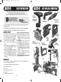
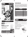
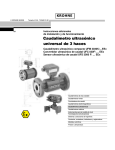
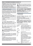
OSA-279-200OK_Manual.qxd
20/11/2006
14:36
Page 1
E C LOW VOLTAGE DIRECTIVE 73/23/EEC
E C ELECTROMAGNETIC COMPATIBILITY DIRECTIVE 89/336/EEC
DECLARATION OF CONFORMITY
We hereby certify that OSAKI MINI-MAX 125 Inverter Welder
Complies with all the relevant provisions of the
EC Directives 73/23/EEC & 89/336/EEC
Harmonised Standards Applied:
EN60974-1 + A1(2000) + A2(2003)
EN50199
MINI-MAX 125 INVERTER
Official Agent
KENNEDY TOOLS
Wigston Works, Leicester, England.
ISO 9002 REGISTERED COMPANY
04
Signed:
Date: 1st October 1999
Name: Martin Cooke
Position: Director, The Kennedy Group Ltd.
QUALITY GUARANTEE & WARRANTY
OSAKI POWER TOOLS carry one years manufacturers warranty.
OSAKI POWER TOOLS are designed & produced
to the highest standards & specifications
OSAKI POWER TOOLS are fully guaranteed against
faulty materials & workmanship
Should they be found to be defective, they will either be repaired or replaced
free of charge (fair wear and tear and/or misuse excepted).
Please retain supplier invoice as proof of purchase.
AVAILABLE FROM YOUR DISTRIBUTOR
ORDER CODE
OSA-279-2000K
99
OPERATORS MANUAL
© The Kennedy Group Ltd. 09/06
OSA-279-200OK_Manual.qxd
20/11/2006
14:36
Page 2
SAFETY INSTRUCTIONS
Osaki Power Tools are committed to the Production of Quality Power Tools
that are designed for high performance and long service life.
If safety and maintenance procedures are observed they will last for many years.
“
Man, Earth and the Universe
are forces that create an
immovable centre of balance . . .
the
balance of power ”
ALSO AVAILABLE FROM OSAKI
12, 14.4
& 16.8 Volt
Cordless Drill/
Screwdrivers
Delta Sander
Multi Purpose
Power Tool
Thank you for choosing our welder! In order to make the most of your equipment, please read the
following very carefully:
The MINI-MAX 5mm is a portable, mono phase, air cooled direct current (DC) Inverter welder, for
electrode welding MMA using all types of electrodes: rutile, basic, stainless steel, etc.
Always run the power cable away from the
back of the welder to guard it from damage.
When working outdoors only use suitably
approved extension cables with a minimum
conductor cross section of 1.5mm2. The plug
connectors must have earthing contacts and
be waterproof.
Secure work with a clamp or vice. This will
allow both hands free to carry out the work.
Disconnect from the power source when not in
use, or when changing accessories/electrodes.
Before using the welder, ensure that all parts
are functional. A damaged part should be
repaired and serviced by an authorised
technician.
Stay alert at all times. Watch what you are
doing and use your common sense. Do not
operate when you are tired.
Do not store the machine in locations where the
temperature may reach or exceed 50oC (122oF).
GENERAL SAFETY
Keep work area clean - clutter invites injury.
Do not expose the inverter welder to rain or
damp conditions. Ensure work area is well lit.
Do not use near flammable liquids or gases.
Do not let people who are not familiar with the
equipment handle it without supervision.
Store in a dry, secure place, away from
children.
Use the correct tool for the job. The job will be
done more efficiently and safely if the tool is
used for it’s intended purpose.
Always wear welders gauntlets/leather gloves,
a leather/fireproof apron and non-slip footwear.
Always wear the welding mask provided or
other propriety protection that includes a
protective clear glass placed in front of a
filtering glass.
Orbital
Jigsaw
160mm
Circular Saw
Orbital
Sheet
Sander
Electric
Nailer/Stapler
13mm
impact drill
IMPORTANT
You must ensure that your inverter is connected to the power source via an earthed plug/wire. If not,
you are at high risk of personal electrocution.
You must take precautions to protect yourself and others from:
Smoke/fumes, fire and burns
Arc radiance
Mini
Milling/Drilling
Machine
Rain, water, steam and humidity
Electric shock
Inflammable environment/elements
2
115mm
Angle Grinder
Mini Lathe
7
OSA-279-200OK_Manual.qxd
20/11/2006
14:36
Page 3
PACEMAKER/DEFIBRILLATORS
SERVICE & REPAIR
All staff/personnel with a pacemaker/defibrillator fitted must be aware that the electromagnetic energy
generated when arc welding may cause your pacemaker to continually pace your heart. If your heart is
beating on its own, this may result in an irregular heart rate. The intense energy created when spot
welding or starting a bead may cause your pacemaker (including the pacemaker function of an
implantable defibrillator) to pause temporarily if it were pacing your heart. Your implantable defibrillator
could detect the electromagnetic energy from the welder (especially when spot welding) as a fast heart
rhythm, causing it to deliver a shock.
A comprehensive in house repair
and service facility is available
through your local agent.
SPECIFICATIONS
Model:
Nominal Voltage
Electrode capacity: Rutile, Basic, Stainless Steel, Cast Iron
Weight
Duty Cycle 100%
Duty Cycle 60%
Duty Cycle 40%
Voltage: Open Circuit (no welding being carried out)
Voltage: Supply
MINI-MAX125
230v~50 Hz
1.6mm - 2.5mm
2.8kg
50A
65A
70A
70v
230v
INSTALLATION
ACCESSORIES/CONSUMABLES
recommends using KENNEDY welding rods available from your nearest
Osaki Distribtuor.
*
Electrodes for Mild Steels
Arc welding rods for mild steel and medium tensile steels.
Medium rutile coated, all positional rods*.
Applications: for steel plate and strip including
structural steels and pipe work, especially under
site conditions.
Superb finish with self-releasing slag.
N.B. Suitable for AC (50V minimum open circuit) and DC +/-.
Order Code
KEN-891
-3010K
-3020K
-3030K
Size
No of Rods
(mm)
(per pack)
2.50 x 300
260
3.25 x 350
150
4.00 x 450
100
Weight
(per pack)
5.0kg
5.0kg
5.0kg
Minimum Maximum
Amperage Amperage
50A
90A
80A
125A
120A
180A
6
1. Flat or Downhand position
2. Fillet welding in the horizontal vertical
position
3. Butt and fillet welding in the vertical
up position
4. Butt and fillet welding using the
vertical down technique
5. Butt welding in the horizontal position
6. Butt and fillet welding in the
overhead position
3
2
1
4
The user is responsible for the installation and use of the equipment in accordance with the
manufacturers instructions.
Before installation, the user should assess the risk of electromagnetic interference on persons
and the environment.
If electromagnetic interference is detected it is the user’s responsibility to remedy the situation
with the help of a professional electrical engineer.
This may be remedied by the introduction of filtering on the supply cable.
The welding machine should not be modified in any way
and should be used only for the purpose for which
it is intended.
When using the machine it is advisable to
arrange cables tidily and together where
possible to minimise risk of tripping.
”
5
6
3
the
balance of power ”
OSA-279-200OK_Manual.qxd
20/11/2006
14:36
Page 4
MACHINE LABELLING
Top Labelling
The generator is a source of high frequency with rectification.
The equipment complies with Standard EN60974-1 relating to welding
machines.
The welding method is a manual arc with coated electrodes
START-UP
Connect the machine to the mains via a 240v plug with a 10A fuse and an earth connection.
Connect the current return lead (earth lead) and the electrode holder to the welder according to
the polarity specified for the chosen electrode to be used.
The welder is activated by turning the potentiometer knob from “0” to the desired current for the
diameter of the selected electrodes to be used.
WELDING
Protection against the risk of electric shock.
The welding current is direct.
Vacuum voltage (with no welding being carried out) is 70V.
Potentiometer scale/current settings/conventional voltage
X: Duty cycle is 35%, 60% & 100%
I2: Corresponding currents
U2: Live conventional voltages
Single-phase electrical feeding 50 or 60Hz..
Be sure to observe all classical welding rules.
Leave the machine connected after welding in order to let it cool down.
Thermal protection: the yellow LED comes on when the thermal cut-out trips due to the unit
overheating. The cooling down time is approx. 5 minutes, signalled when the light goes out.
The machine is equipped with the following functions;
HOT START, allows a super intensity of roughly 25% on the setting;
ARC FORCE, allows a super intensity of roughly 55% on the setting to avoid sticking when
the electrode enters the pool; and
Mains feed voltage
Maximum Feeding Current .
ANTI STICKING, allows you to remove your electrode easily from the pool without it sticking.
Current of the maximum effective feeding.
PROBLEMS
Indication IP21C, protection against the penetration of solid strange
bodies and vertical water falls but not under the rain
Electrical installation protection with a fuse 10A
It is obligatory to wear the UV protection helmet.
Warning! Hot sparks are produced during the welding process.
Front Labelling
Potentiometer for Setting the appropriate Current for
te diameter of the selected elcetrode
If you are ready to weld and the machine does not produce current, please study the following
possible solutions.
If both LEDs are on, wait for the cooling down period until the yellow light (thermal cut-out)
switches off, reintroducing the required working current. If there is still no current,return the
machine to your OSAKI distributor for repair.
If the POWER (green light) is off, check the supply connections. If none are found to be faulty,
return the machine to your OSAKI distributor for repair.
If you touch the workpiece after you have finished welding and get a tingling sensation, this
means that the unit is incorrectly earthed, check for faulty connections on all plugs and
extensions
MAINTENANCE
Green LED for Power ON
Yellow LED for Thermal Cut Out
MAX 5mm refers to the maximum thickness of metal to be welded
Positive connection for the Electrode Holder
Negative connection for the Earth Clamp
Disconnect the welder and wait until the cooling fans have stopped because the internal
voltage and current are high are dangerous.
Take the steel cover off regularly to inspect and clean dust from the internal components using
compressed air (be sure you wear eye protection and a dust mask), making sure that the
machine is no longer coneted to the mains supply
(unless specified otherwise by the elec trode manufacturer)
4
5