1
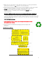
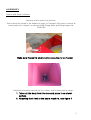
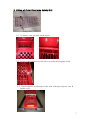
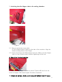
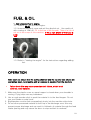
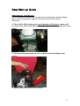
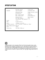
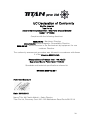
THE TITAN PRO 15 HP PETROL CHIPPER/SHREDDER/MULCHER OPERATORS MANUAL AND PARTS LIST Spares & Support: 0845 6800 962 Important: Please fully read and understand this manual before using this machine paying particular attention to the safety instructions. 1 CONTENTS SAFETY INSTRUCTIONS & WARNING LABELS 3-4 ASSEMBLY 5-9 FUEL & OIL 10 OPERATION 1011 MAINTENANCE & STORAGE 1113 EASY START UP GUIDE 1416 SPECIFICATIONS 17 PARTS DIAGRAM & LIST 1819 EC DECLARATION OF CONFORMITY 20 2 SAFETY INSTRUCTIONS Read and understand this owner’s manual and labels that are affixed to the chipper /shredder. Learn the chippers applications and limitations as well as the specific potential hazards. Please retain these instructions for future reference. Use sturdy footwear also eye and ear protection, wear heavy duty gloves. Do not operate the machine if you are tired, ill or under the influence of alcohol or drugs. Do not smoke when using the chipper/shredder and use caution when you are handling fuel. We recommend that you re fuel the machine at least 3 Metres away from where you wish to work in case any split fuel ignites when starting the engine. Always ensure the fuel cap in tight and correctly fitted before starting. Ensure bystanders, children or pets are at least 15 meters away when starting the machine or chipping. Keep the operator area clear of other objects. Examine the machine to ensure its in good condition, check all the screws, nuts and other fasteners are properly secured and the screen is in place. If the fuel tank needs to be drained, it should be done outdoors. Be aware of the hot exhaust, when the machine is in operation touching the exhaust can cause burns. Keep a proper balance and footing at all times. Do not over reach. Never stand at a higher level than the base of the machine when feeding material into it. Keep your face and body away from the feed intake opening. Do not allow hands or any other parts of the body or clothing inside the feed hopper, side chute, discharge chute, or other rotating parts. 3 Make sure your work area is clear and the machine is on level ground before starting the machine; do not operate in an enclosed area. Ensure that the plastic protection cover on the top hopper is intact and closed when the chipper shredder is running to avoid any debris coming out. NEVER put your hands into the hopper or side chute to push material through. If necessary use a wooden stick.DO NOT use a metal implement. Important additional safety instructions for machine with bagging attachment Before attaching or removing the bag, the engine should be turned off. Cover the discharge opening with a fabric bag and tighten the cord in the mouth of the bag. When the machine is working, all the chips are collected in the bag. Empty bag when full Wood Shredder operation Never attempt to move or clear any blockage in the machine whilst the engine is still running. Please recycle the cardboard packaging that the chipper was packed in. WARNING LABELS 4 ASSEMBLEY Unpack and check contents. Remove all the items from the box. Some items are stored in the hopper for ease of Transport. Be sure to remove all loose parts from Hopper, by removing M8 Flange bolts and lifting hopper lid. Photo1&2 1 Make sure Hopper is empty before securing lid on hopper 2 Assembly should be carried out on a clean, level surface with a helper. 1. Take out the body from the box and place it on a level surface 2. Attaching front foot to the basic machine, see figure 2 5 Figure 2 Remove the nuts from bolts 1, 2, Remove the bolts and pipe spacer. Pull Down chute from the TRANSPORT position to the correct operational position. Attach front foot 5, to the side plate of the cutting chamber and align the mounting holes with holes 1, 2. Put the pipe spacer that was removed in step 1 back in place. Insert the bolts and secure them tightly. Please ensure Lower discharge chute is facing towards the ground and is BELOW the pipe spacer as shown in the photographs in this section Correct Fitting position of Bottom Discharge Chute 6 3. Fitting of Outer Discharge Safety Grill Safety Grill 3.1. Fit hooks over top bar inside chute. 3.2. Attach side brackets to the bolts on sides and tighten bolts. 3.3. Place support rod through holes and slide pipe spacer over & tighten nuts. 7 Correct fitting of bottom discharge chute (outer grid not yet installed) Incorrect fitting of Bottom Discharge Chute 4. Attach axle bracket/axle and tyres. See picture 3. Picture 3 4.1. Put the rear axle bracket in place and align the mounting holes. 4.2. Insert M8*20 bolts in holes from outside to inside and secure them with washers and nuts. 8 5. Attaching the side chipper tube to the cutting chamber. Figure 4 5.1. Remove protective cover plate. Put the chipper tube in place on the side of the machine. Align the three mounting holes in the flange. 5.2. Secure the flange with M8 washers and nuts. Make sure the chipper tube is in the correct position before tightening up the nuts. 6. Mounting the two handles 6.1. Secure the 2 hopper handles as shown Tighten M6 nuts from the inside of hopper. Bolt down hopper lid when completed. 7. Check all screws, bolts, and nuts and tighten them if loose. 9 FUEL & OIL 1. Add unleaded fuel to engine. 1.1. There is no oil in the new engine. 1.2. Unscrew the black cover and pull the dipstick out. Use quality oil with a rating of 15W-40. Fill to the top of the threads. There is a low oil cut out in the sump of this machine, IT WILL NOT START IF THE OIL IS LOW 1.3. Refer to “starting the engine” for the instructions regarding adding fuel. OPERATION After each use ensure that the cutting chamber and the top and side chutes are completely clear, run machine until all produce is expelled from the machine Failure to do this may cause premature belt failure, which is not covered under warranty. 1. Make sure the plastic cover on upper hopper is closed when your shredder is running. Flying chips are very hazardous. 2. Use a rough wooden stick to push the material in to the feed hopper. Do not use your hands or metal tools. 3. Big branches must be fed comparatively slowly into the machine side chute. 4. Do not allow processed material to build up in the discharge zone; this may prevent proper discharge and can result in kickback of material through the feed intake opening and may cause the drum to stop and belt to overheat 10 5. If the machine becomes clogged, immediately turn off the engine before clearing the debris. Keep the engine clear of debris and other accumulations to prevent damage to engine or possible fire. 6. Never rest items on the cover of hopper in case they may fall into the machine. 7. To move the machine, firmly hold the handles with both hands, step on the Axle on the rear wheel with one foot, lift the front of machine, pay attention to centre of gravity of machine, walk slowly forward, backward or turn around as required. 8. Before operating the machine, please check the direction of the wind to avoid working downwind of exhaust. 9. Keep all guards and deflectors in place and in good working condition. 10. The exhaust and engine become hot and can cause a burn. Do not touch. 11. Turn off machine before transporting the machine. 12. Do not tilt the machine while the engine is running. MAINTENANCE & STORAGE 1. When the machine needs servicing, inspection, or storage, or to replace a part, turn off the engine, make sure all the moving parts are completely stopped and allow the machine to cool before making any inspections, adjustment etc. 2. Store the machine where fuel vapours will not reach an open flame or spark. If the machine is stored for a long time, drain the fuel out of the machine. Make sure the machine is cool before storing. 3. When the cutting blades need servicing, remove them manually when the machine is stopped and the spark plug removed from the engine for safety. Branch chipping 1. Long branches etc are fed into the side chipping tube for chipping by the rotating blade. 2. Some side shoots and branches may have to be trimmed from the main stalk before chipping. 3. Shorts stubs of branches may be pushed through the chipper section with the next branch, never use your hand. 4. The last branch is pushed inside the tube using a tool like a wooden stick. Never use your hand or a metal object. 5. Never push the small branches by hand, use a wooden stick instead. 11 6. When feeding branches, be certain that thicker branches are pushed slower than thin ones. A technique and understanding of the feed rate will be acquired to successfully shred very quickly. 7. Do not allow any accumulation of processed material to build up under discharge of the shredder-chipper as this can result in clogging. Use wood tools to clear the build up. 8. Do not put your face close to the feed hopper. This may result in injury. 9. Do not stand in front of discharge opening and never attempt to open the outlet of discharge while machine is on operation. 10. Put back the cover on the side feed tube once you have finished chipping. Leaves Leaves and short stalk plants, cobs, and similar material should be Fed into the hopper and chipped in interlaced chipping bundles. 1. Do not remove the plastic cover when adding more material. 2. If the leaves and similar material proves difficult to enter the hopper, use a wooden stick to push them in, NO NOT use your hands, or anything metal. 3. Keep your face and body away from the feed hopper to avoid being struck by any material that may bounce back. 4. The discharge area is easily clogged if the material is moist or wet. Always stop the engine before clearing build-up with wood tools. Never use your hand or feet. 5. Never attempt to clear an accumulation of processed material when engine is still running. Keep pets and bystanders away from the discharge area while the machine is running. Sharpening the blade The cutting blade is made of special material and the blade is very sharp after being heat treated. It will become dull or blunt after being used for some time. Tel tale signs of a dull blade: when the chipping sound becomes very ponderous and the belt always slips when it is not loose, or feeding speed gets slow, please remove the blade and check if it is blunt. 1. Turn off the engine and remove spark plug before removing the blade. Remove the Inspection Plate on the side of the chamber covering the blade. Open the small outlet of the discharge. Remove the discharge screen. 2. Wearing safety gloves turn the blade flywheel so the blade is visible through the side chamber. 12 3. Remove the 3 Allen machine screws on the blade by using a Allen key in the front and rotating the lock nut on the back with a ring spanner 4. Sharpen the blade. If the blade is damaged by metal or stone or other hard objects please sharpen the damaged area. Avoid changing the blade colour and anneal when sharpening the blade. It may result in a break on the edge of the blade Cutting angle should be kept within 45-40 degrees. The two blades should retain the same weight. Vibration will occur if they differ. Position the blade on the flywheel and tighten the nuts. Replace the inspection Plate covering the blade. Replace the discharge screen. Adjust the outlet of the discharge chute. Adjusting the belt - Always Wear Gloves There is a “V” belt under the belt guard. The belt will become loose and slip after using for some time. So re-tension adjustment is required. 1. Turn off the engine, remove spark plug and remove the belt cover. 2. Loosen the four location nuts on the engine. 3. Move engine forward until the “V” belt is tight. 4. Align the main pulley and affiliated pulley so that they are on the same plane. (A ruler can be used to measure for correct distance). Tighten the four location bolts on the engine base. 5. Re fix the belt cover back in its correct position and tighten nuts. Replacing the belt - Always wear Gloves The “V” belt needs to be replaced if it is has stretched or been damaged. 1. Turn off the engine, remove spark plug and remove the belt cover. 2. Loosen the 4 bed bolts on the engine slightly (Do not completely undo as this will let a baffle fall down inside the drum). 3. Remove the old belt. Pull the belt off using tools and turn the pulley gradually to remove the belt from the pulley. Note: Take care not to trap fingers in belt/pulley. 4. Place the new belt on the main pulley first (“V” belt on engine) and then ease onto the lower pulley on the blade flywheel. 5. The new belt will be tighter than the old one. To assemble the new one is not as easily as removing the old one. When you hold the belt into the slot of the pulley wheel, do not put your finger between the pulley and belt, which may result in injury. 6. Follow step 4 (Adjusting the belt) to align correctly 7. Replace the belt cover. 13 Easy Start up Guide Important pre starting note Before starting it is essential that you make sure the Top hopper & Side chipping chute is clear of all produce, make sure the drum rotates freely without obstruction 1. Check Oil is filled right up to top of threads on filler hole, engine will not start if the oil is not at this level as there is a low oil level cut out in the sump. 2. Fill up fuel in petrol tank, do not overfill, and avoid spillage onto engine. 3. Adjust throttle lever to Mid Position. 14 4. Adjust Choke to far left position. 5. Turn the switch to the ON position. 6. Using the Pull Start, pull the pull cord strongly to its full extent. 15 7. Once started turn choke to Right-hand side (OFF) position to allow engine to run smoothly. 8. To Stop Engine turn switch to OFF position. Important User Information After each use ensure that the cutting chamber and the top and side chutes are completely clear of produce, continue to run the chipper until ALL produce is expelled from the machine. DO NOT PUT HANDS INTO MACHINE Failure to carry this may cause the safety drive belt mechanism to jam Resulting in a belt failure which is NOT covered under Warranty 16 SPECIFICATIONS Shredder chipper TITAN 15HP ENGINE: Type of engine: Titan/Lifan 190F Carburettor type: Single cylinder,4 stroke Displacement: 420cc Max. engine speed: 3600r/min Max. engine power: 8.5kw/3600r/min Starting mode: Recoil starter Fuel tank capacity: 6.5L Lubricating oil tank capacity: 1.1L RATE: 1.74:1 Belt: V-belt B section Knife: 1 Blade = ( one set) Chipping capacity: Size: 110/50mm; 128/88 mm ( Max) Max chipping speed: 26m3/h N.W: 105kg Carton Size 780*460*1180(mm) All photographs are the copyright of Titan Pro Ltd and all graphic design on this Manual are the copyright of Titan Pro Ltd. The copyright in all content included in this manual such as photographs, illustrations, text, is owned by either us or our content providers. No reproduction of anything in this manual is licensed without the written consent of Titan Pro, as protected by "The copyright Designs and Patents act 1988" 17 PARTS DIAGRAM 18 PARTS LIST Qty No. 1 Description Rubber Foot Qty 32 Description Plate 2 2 Front Support 1 33 Blade Flywheel 1 3 Flat Washer many 34 Key 1 4 Hex Nut many 35 Rear Board 1 5 Lock Washer many 36 Engine Seat 1 6 Hex Bolt 1 37 7 Discharge Chute 1 38 Rubber Gasket 1 8 Movable Door 1 39 Hopper 1 9 3 40 1 41 1 42 Handle Grip Hook Hex Bolt 2 11 Tube Screen Safety Grid many 12 Hitch Pin 2 43 Engine Exhaust Guard 1 13 Door axle 2 44 Centrifugal Clutch 1 14 Spacer I 4 45 V-belt 1 15 Spacer II 8 46 Belt Cover 1 16 Spacer III 4 47 Belt Cover Bracket 1 17 Flail Hammers 16 48 Spacer 1 18 Spacer VI 4 49 Pulley 1 19 Roll Pin 4 50 Spacer 1 20 Hammer Axis 4 51 Spacer 1 21 Blade 1 52 Chamber R/HSide Frame 1 22 Blade Screw 3 53 Wheel Housing 2 23 Chamber L/HSide Frame 1 54 24 Wheel 2 55 Front Handle 2 25 Wheel Support 1 56 Front Handle Support 1 26 Blade Cover Plate 1 57 Rear Handle 4 27 Cir Clip 1 58 28 Washer (right) 1 59 Towing Bar 1 1 60 Bolt 1 No. 10 29 Side Chipping Chute 30 Bearing Housing 2 31 Bearing 2 1 2 19 EC Declaration of Conformity We,The Importer Titan Pro ltd Declare that the product Titan 15hp Petrol Chipper/Mulcher Model – TP15Chip Complies with the following directives: 2006/42/EC- Machinery Directive 2004/108/EC-Electromagnetic Compatibility Directive 2005/88/EC – Noise Emission in the Environment by equipment for use outdoors Directive. The conformity assessment procedure was followed in accordance with Annex V of the Directive 2000/14/EC. Measured Sound Pressure level: 108.4db(A) Guaranteed Sound Power level: 110db(A) Standards and technical specifications referred to: EN13683:2003+A2:2011 Authorised Signature Date: 30/09/2012 Name/Title: Mr Charlie Abbott – Sales Director Titan Pro ltd ,Discovery Court 551-553 Wallisdown Road Poole BH12 5A 20