1
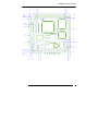
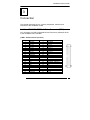
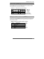
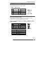
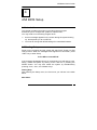
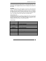
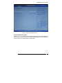
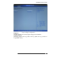
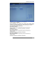
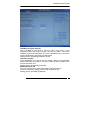
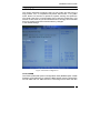
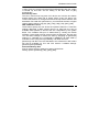
AR-B8020 User’s Guide
AR-B8020
R8610 Processor with LAN, PCI/104, COMs,USB 2.0
Onboard SSD.
Edition: 1.1
Book Number: AR-B8020-08.07.22
AR-B8020 User’s Guide
@Copyright 2005
All Rights Reserved.
Manual first edition Nov 22, 2005
The information in this document is subject to change without prior
notice in order to improve reliability, design and function and does not
represent a commitment on the part of the manufacturer.
In no event will the manufacturer be liable for direct, indirect, special,
incidental, or consequential damages arising out of the use or inability to
use the product or documentation, even if advised of the possibility of
such damages.
This document contains proprietary information protected by copyright.
All rights are reserved. No part of this manual may be reproduced by
any mechanical, electronic, or other means in any form without prior
written permission of the manufacturer.
Trademarks
AR-B8020 is registered trademarks X-Fire Acrosser, IBM PC is a
registered trademark of International Business Machines Corporation.
Pentium is a registered trademark of Intel Technologies, Inc. Award is
registered trademarks of Award Software International, Inc. Other
product names mentioned herein are used for identification purposes
only and may be trademarks and/or registered trademarks of their
respective companies.
AR-B8020
2
AR-B8020 User’s Guide
Contents
Contents ................................................................ 3
Introduction ............................................................. 5
1.1 Specifications:........................................................................... 5
1.2 What You Have......................................................................... 6
Installation .............................................................. 7
2.1 AR-B8020’s Layout................................................................... 7
2.2 Power description ..................................................................... 9
2.3 CMOS Reset............................................................................. 9
2.4 Jumper description ................................................................... 9
Connection............................................................ 10
3.1 Ultra ATA33/66 IDE Disk Drive Connector(IDE1) .................. 10
3.2 Serial Ports(COM1~3) ............................................................ 11
3.3 Keyboard / Mouse Connector(KBMS1) .................................. 11
3.4 USB Port Connector(USB1~2) ............................................... 12
3.5 Front Connector (CN4) ........................................................... 12
3.6 LAN pin header(J3)................................................................. 13
3.7 FDD(FDD1)............................................................................. 13
3.8 8-BIT GPIO Connector(GPIO1) .............................................. 14
AR-B8020
3
AR-B8020 User’s Guide
AMI BIOS Setup ................................................... 15
4.1 Introduction ............................................................................. 15
4.2 Starting Setup ......................................................................... 15
4.3 Standard CMOS Features ...................................................... 17
4.4 Advanced BIOS Features ....................................................... 18
4.5 PCI PnP .................................................................................. 25
4.6 Boot………………………………………………………………..27
4.7 Security ................................................................................... 31
4.8 Exit…………………………………………………………………32
Appendix A. Watchdog Timer ............................... 33
Appendix B: Digital I/O.......................................... 35
Appendix C: Memory Address Map ...................... 37
AR-B8020
4
AR-B8020 User’s Guide
1
Introduction
1.1 Specifications:
CPU : RDC R8610 133 MHz, L1 Cache 16KB, 216pin LQFP
RAM memory : Onboard 64MB default, Min 32MB optional
IDE Interface : 1 x 44-P 2x22x2.0mm support ATA-33 (ITE8211F)
Series ports : Three high-speed 16C550 compatible UARTs ports.COM2/3
can also support RS-485.
USB port : Support Two USB 2.0 compatible ports.
Digital IO : Supports eight digital-in, and eight digital-out TTL-level I/O ports.
PS/2 Mouse/Keyboard : Keyboard Mouse pin header
Extention Bus: PC/104 Plus Connector
SSD : Onboard Solid-State Drive(SSD) 128MB default, Max 256MB optional
Watchdog timer : Time setting form 1 to 255 second / minute System Reset
generate when CPU did not periodically trigger the timer.
Intel LAN Controller: Single ports IEEE 802.3u Auto-Negotiation support for
IC+ IP101A 10/100BASE-TX Connected to your LAN through pin header.
Power Consumption : 12V / 5V
Operating Temperature : -10° ~ 60° C ( CPU needs Cooler)
Dimension: 90.17mm(W) X m95.88m(L)
AR-B8020
5
AR-B8020 User’s Guide
1.2 What You Have
In addition to this User's Manual, the AR-B8020 package includes the
following items:
AR-B8020 board
User Manual
Drive CD
AR-B8020
6
AR-B8020 User’s Guide
2
Installation
This chapter describes how to install the AR-B8020. At first, the
layout of AR-B8020 is shown, and the unpacking information that you
should be careful is described. The jumpers and switches setting for
the AR-B8020’s configuration
2.1 AR-B8020’s Layout
AR-B8020
7
AR-B8020 User’s Guide
AR-B8020
8
AR-B8020 User’s Guide
2.2 Power description
• CN3 : power connecter
PIN NO.
1
2
3
4
DESCRIPTION
+12V
GND
GND
+5V
• JP6: PCI-104 +3.3V source from on board or other
JP6
Description
Short
Open
+3.3V on board
other
2.3 CMOS Reset
• JP7: CMOS Reset
JP7
1-2
2-3
DESCRIPTION
Normal Operation
Clear CMOS
2.4 Jumper description
• JP5 : Short SERIRQ Connect to PCI104 Pin B1
JP5
Short
Open
Description
Connect
Unconnect
• JP9/JP10 : Select COM2/3 is RS232 or RS485
JP9/JP10
1-2
2-3
DESCRIPTION
RS232
RS485
AR-B8020
9
AR-B8020 User’s Guide
3
Connection
This chapter describes how to connect peripherals, switches and
indicators to the AR-B8020 board.
3.1 Ultra ATA33/66 IDE Disk Drive Connector(IDE1)
You can attach one IDE( Integrated Device Electronics) hard disk drives
to the AR-B8020 IDE controller.
• IDE1 : IDE Connector (44 Pins)
PIN NO.
1
3
5
7
9
11
13
15
17
19
21
23
25
27
29
31
33
35
37
39
41
43
DESCRIPTION
RESET#
DATA 7
DATA 6
DATA 5
DATA 4
DATA 3
DATA 2
DATA 1
DATA 0
GROUND
N/C
IOW#
IOR#
N/C
N/C
INTERRUPT
SA1
SA0
HDC CS0#
HDD ACTIVE#
+5V LOGIC
GROUND
PIN NO.
2
4
6
8
10
12
14
16
18
20
22
24
26
28
30
32
34
36
38
40
42
44
DESCRIPTION
GROUND
DATA 8
DATA 9
DATA 10
DATA 11
DATA 12
DATA 13
DATA 14
DATA 15
N/C
GROUND
GROUND
GROUND
BALE - DEFAULT
GROUND - DEFAULT
IOCS16#-DEFAULT
N/C
SA2
HDC CS1#
GROUND
+5V MOTOR
TYPE
AR-B8020
10
AR-B8020 User’s Guide
3.2 Serial Ports(COM1~3)
The AR-B8020 offers two high speeds NS16C550 compatible UARTs
with Read/Receive 16 byte FIFO serial ports.
• COM1/2/3 : RS-232 Serial port (Pin Header)
PIN
1
3
5
7
9
DESCRIPTION
-DCD
RXD
TXD
-DTR
GND
PIN
2
4
6
8
10
DESCRIPTION
-DSR
-RTS
-CTS
-RI
GND
NOTE : COM1(I/O BASE:3F8), COM2(I/O BASE:2F8) , COM3(I/O BASE:3E8)
3.3 Keyboard / Mouse Connector(KBMS1)
A PS/2 type connector(MSKB1)is for easy connection to a keyboard and
PS/2 mouse. The board comes with a Y split PS/2 cable for keyboard
and mouse pin header.
• KBMS1: Keyboard and Mouse port(Pin Header)
PIN NO.
1
2
3
4
5
6
DESCRIPTION
M_DATA
K_DATA
GND
+5V
M_CLK
K_CLK
AR-B8020
11
AR-B8020 User’s Guide
3.4 USB Port Connector(USB1~2)
The AR-B8020 provides two USB pin header.
• USB1 : USB Pin header
PIN
1
3
5
7
9
DESCRIPTION
VCC
USB1USB1+
GND
USB_GND
PIN
2
4
6
8
10
DESCRIPTION
VCC
USB2USB2+
GND
USB_GND
3.5 Front Connector (CN4)
The AR-B8020 provides one connectors for two RS485 and HDD
LED ,RESET ,SPEAKER ,POWER LED(Pin Header).
• CN4 : Two RS485 with HDD LED and RESET ,SPEAKER ,POWER
LED(Pin Header)
PIN
1
3
5
7
9
11
DESCRIPTION
TX0+
TX0+5V
GND
+5V
RESET
PIN NO.
1-3
2-4
5-7
6-8
9-10
11-12
PIN
2
4
6
8
10
12
DESCRIPTION
TX1+
TX1+5V
IDE_LED
SPEAKER
GND
DESCRIPTION
RS485(COM2)
RS485(COM3)
POWER LED
HDD LED
SPEAKER
RESET
AR-B8020
12
AR-B8020 User’s Guide
3.6 LAN pin header(J3)
AR-B8020 is equipped with built-in 10/100Mbps Ethernet Controller. You
can connect it to your LAN through LAN pin header. The pin
assignments are as following:
• J3 : LAN port(Pin Header)
PIN NO.
1
2
3
4
5
6
7
DESCRIPTION
TX+
TXRX+
RXGND
Connect RC Circuit to Ground
Connect RC Circuit to Ground
3.7 FDD(FDD1)
AR-B8020 board is equipped with a 16-pin daisy-chain driver connecting
cable.
• FDD1 : Floppy port (Pin Header)
PIN
1
3
5
7
9
11
13
15
DESCRIPTION
DENSEL
DR#
GND
STEP#
WGATB#
GND
RDATA#
DSKCHG#
PIN
2
4
6
8
10
12
14
16
DESCRIPTION
INDEX#
MTR#
DIR#
WDATA#
TRK#
WRTPRP#
HSIDE#
GND
AR-B8020
13
AR-B8020 User’s Guide
3.8 8-BIT GPIO Connector(GPIO1)
• GPIO1 : Connector(Pin header)
PIN
1
3
5
7
9
DESCRIPTION
GPIO0
GPIO2
GPIO4
GPIO6
GND
PIN
2
4
6
8
10
DESCRIPTION
GPIO1
GPIO3
GPIO5
GPIO7
+5V
AR-B8020
14
AR-B8020 User’s Guide
4
AMI BIOS Setup
4.1 Introduction
This chapter provides information on the BIOS Setup program
and allows you to configure the system for optimum use.
You may need to run the Setup program when:
An error message appears on the screen during the system booting
up, and requests you to run SETUP.
You want to change the default settings for customized features.
4.2 Starting Setup
Power on the computer and the system will start POST (Power On Self
Test) process. When the message below appears on the screen, press
<DEL> key to enter Setup.
Press DEL to enter SETUP
If the message disappears before you respond and you still wish to enter
Setup, restart the system by turning it OFF and On or pressing the
RESET button. You may also restart the system by simultaneously
pressing <Ctrl>, <Alt>, and <Delete> keys.
Getting Help
After entering the Setup menu, the first menu you will see is the Main
Menu.
Main Menu
AR-B8020
15
AR-B8020 User’s Guide
The main menu lists the setup functions you can make changes to. You
can use the control keys ( Up/Down Arrow ) to select the item. The on-line
description of the highlighted setup function is displayed at the bottom of
the screen.
Sub-Menu
If you find a right pointer symbol appears to the left of certain fields that
means a sub-menu containing additional options can be launched from
this field. You can use control keys ( Up Arrow ,Down Arrow ) to highlight
the field and press <Enter> to call up the sub-menu. Then you can use
the control keys to enter values and move from field to field within a submenu. If you want to return to the main menu, just press <Esc >.
General Help <F1>
The BIOS setup program provides a General Help screen. You can call
up this screen from any menu by simply pressing <F1>. The Help screen
lists the appropriate keys to use and the possible selections for the
highlighted item. Press <Esc> to exit the Help screen.
Control Keys
Key
Up/Down Arrow
Right/Left Arrow
+/- Key
Enter key
PGDN key
PGUP key
HOME key
END key
F2/F3 key
F7 key
F8 key
F9 key
F10 key
ESC key
Function
Select Screen
Select Item
Change Option/Field
Go to Sub Screen
Next Page
Previous Page
Go to Top of Screen
Go to Bottom of Screen
Change Colors
Discard Changes
Load Failsage Defaults
Load Optimal Defaults
Save and Exit
Exit
AR-B8020
16
AR-B8020 User’s Guide
4.3 Standard CMOS Features
The items in Standard CMOS Features Menu are divided into several
categories. Each category includes no, one or more than one setup
items. Use the arrow keys to highlight the item and then ue the <PgUp>
or <PgDn> keys to select the value you want in each item.
Figure 1 Standard CMOS Features
System Time
This allows you to set the system time that you time format is <hour>
<minute> <second>.
System Date
This allows you to set the system to the date that The format is
<day><mnth> <date> <year>.
day Day of the week, from Sun to Sat, determined by BIOS. Read-only.
month The month from Jan. through Dec.
date The date from 1 to 31 can be keyed by numeric function keys.
year The year can be adjusted by users.
AR-B8020
17
AR-B8020 User’s Guide
4.4 Advanced BIOS Features
Figure 2 IDE Configuration
IDE Configuration
The IDE adapters control the hard disk drive. Use a separate sub menu
to configure each hard disk drive.
AR-B8020
18
AR-B8020 User’s Guide
Figure 3 Primary IDE Master/Slave
Primary IDE Master/ Slave
Press <+> or <-> to select the hard disk drive type. The specification of
hard disk drive will show up on the right hand according to your selection.
Press <Enter> for the sub-menu of each item:
AR-B8020
19
AR-B8020 User’s Guide
Figure 4 Primary IDE Master
Device
This item shows the information about the specified item (Read-only).
Type
This item defines the HDD parameters.
LBA/Large Mode
This item allows you to enable or disable the LBA (Logical Block Address,
the logical block size in hard disk) mode.
Setting options: [Auto], [Disabled].
Block Mode
When the setting is Auto, it will read or write more sector at every circle
to enhance the hard disk performance.
Setting options: [Auto], [Disabled].
PIO Mode
The PIO (Programmed Input/Output) Mode let you set a PIO mode (0-4)
for the IDE devices that the onboard IDE interface supports. Modes 0
AR-B8020
20
AR-B8020 User’s Guide
through 4 provide successively increased performance. In Auto mode,
the system automatically determines the best mode for each device. The
settings are: [Auto], [Mode 0], [Mode 1], [Mode 2], [Mode 3], [Mode 4].
DMA Mode
This item allows you to enable or disable the DMA (Direct Memory
Access) mode.
Setting options: [Auto].
Hard Disk S.M.A.R.T.
This allows you to activate the S.M.A.R.T. (Self-Monitoring Analysis &
Reporting Technology) capability for the hard disks. S.M.A.R.T is a utility
that monitors your disk status to predict hard disk failure. This gives you
an opportunity to move data from a hard disk that is going to fail to a safe
place before the hard disk becomes offline.
Settings: [Auto], [Enabled], [Disabled].
32Bit Data Transfer
This allows you to activate the 32bit data transfer to enhance the IDE
hard disk performance.
Settings options: [Enabled], [Disabled].
AR-B8020
21
AR-B8020 User’s Guide
Figure 5 Floppy Configuration
Floppy A
This item allows you to set the type of floppy drives installed.
Available options:
[Disabled], [360K, 5.25 in.], [1.2M, 5.25 in.], [720K, 3.5 in.], [1.44M, 3.5
in.], [2.88M, 3.5 in.].
AR-B8020
22
AR-B8020 User’s Guide
Figure 6 Super IO Configuration
Onboard Floppy Controller
Select [Enabled] if your system has a floppy disk controller (FDD)
installed on the system board and you wish to use it. If you install add-on
FDC or the system has no floppy drive, select [Disabled] in this field.
The settings are: [Enabled], [Disabled].
Serial Port 1 Address
Select an address and corresponding interrupt for Serial Port 1.
Setting options:
[Disabled], [3F8/IRQ7] , [2F8/IRQ7], [3E8/IRQ7], [2E8/IRQ7].
Serial Port 2 Address
Select an address and corresponding interrupt for Serial Port 2.
Setting options:
[Disabled], [3F8/IRQ4], [2F8/IRQ3], [2E8/IRQ3].
Serial Port 1 Address
Select an address and corresponding interrupt for Serial Port 3.
Setting options:
[Disabled], [3F8/IRQ4], [3E8/IRQ4], [2E8/IRQ3].
AR-B8020
23
AR-B8020 User’s Guide
Figure 7 USB Configuration
USB Device Legacy Support
Set to Enabled if your need to use any USB 1.1/2.0 device in the
operating system that does not support or have any USB 1.1/2.0 driver
installed, such as DOS and SCO Unix. Set to Disabled only if you want to
use any USB device other than the USB mouse.
Setting options: [Disabled], [Enabled], [Auto].
USB 2.0 Controller
Set to [Enabled] if you need to use any USB 2.0 device in the operating
system that does not support or have any USB 2.0 driver installed, such
as DOS and SCO Unix.
Setting options: [Fullspeed], [Hispeed].
BIOS EHCI Hand-Off
This is a workaround for Oses without EHCI hand-off support.
The EHCI ownership change should claim by EHCI driver.
Setting options: [Enabled], [Disabled].
AR-B8020
24
AR-B8020 User’s Guide
4.5 PCI PnP
This section describes configuring the PCI bus system and PnP (Plug &
Play) feature. PCI, or Peripheral Component Interconnect, is a system
which allows I/O devices to operate at speeds nearing the speed the
CPU itself uses when communicating with its special components. This
section covers some very technical items and it is strongly recommended
that only experienced users should make any changes
to the default settings.
Figure 8 PCI PnP Configuration
Clear NVRAM
The ESCD (Extended System Configuration Data) NVRAM (Non-volatile
Random Access Memory) is where the BIOS stores resource information
for both PNP and non- PNP devices in a bit string format. When the item
AR-B8020
25
AR-B8020 User’s Guide
is set to [Yes], the system will reset ESCD NVRAM right after the system
is booted up and then set the setting of the item back to [No]
automatically.
PCI Latency Timer
This item controls how long each PCI device can hold the bus before
another takes over. When set to higher values, every PCI device can
conduct transactions for a longer time and thus improve the effective PCI
bandwidth. For better PCI performance, you should set the item to higher
values. Setting options: [32], [64], [96], [128], [160], [192], [224], [248].
IRQ 3/4/5/9/10/11/14/15
These items specify the bus where the specified IRQ line is used.The
settings determine if BIOS should remove an IRQ from the pool of
available IRQs passed to devices that are configurable by the system
BIOS. The available IRQ pool is determined by reading the ESCD
NVRAM. If more IRQs must be removed from the IRQ pool, the end user
can use these settings to reserve the IRQ by assigning an [Reserved]
setting to it. Onboard I/O is configured by AMIBIOS. All IRQs used by
onboard I/O are configured as [Available]. If all IRQs are set to
[Reserved], and IRQ 14/15 are allocated to the onboard PCI IDE, IRQ 9
will still be available for PCI and PnP devices. Available settings:
[Reserved] and [Available].
Reserved Memory Size
Size of memory block to reserve for legacy ISA devices.
Setting options: [Disabled], [16K], [32K], [64K].
AR-B8020
26
AR-B8020 User’s Guide
4.6 Boot
Figure 9 Boot Setting
AR-B8020
27
AR-B8020 User’s Guide
Figure 10 Boot Setting configuration
Boot settings Configuration
Press <Enter> to enter the sub-menu, and the following screen appears.
Quick Boot
Select Enabled to reduce the amount of time required to run the poweron self-test (POST). A quick POST skips certain steps. We recommend
that you normally disable quick POST. It is better to find a problem during
POST than lose data during your work.
Setting options: [Enabled], [Disabled].
Wait For ‘F1’ If Error
Wait for F1 key to be pressed if error occurs.
Setting options: [Enabled], [Disabled].
Hit ‘DEL’ Message Display
Displays ‘Press DEL to run Setup’ in POST.
AR-B8020
28
AR-B8020 User’s Guide
Setting options: [Enabled], [Disabled].
Figure 11 Boot Device Priority
Boot Device Priority
Press <Enter> to enter the sub-menu, and the following screen appears.
1st/2nd/3rd Boot Device
The items allow you to set the sequence of boot devices where BIOS
attempts to load the disk operating system.
AR-B8020
29
AR-B8020 User’s Guide
Figure 12 Removable Drives
Removable Device
Press <Enter> to enter the sub-menu, and the following screen appears.
1st/2nd/3rd Boot Device
The items allow you to specifies the Boot Device Priority sequence from
available Removable Drives.
AR-B8020
30
AR-B8020 User’s Guide
4.7 Security
Figure 13 Change Supervisor Password
Type the password, up to six characters in length, and press <Enter>.
The password typed now will replace any previously set password from
CMOS memory. You will be prompted to confirm the password. Retype
the password and press <Enter>. You may also press <Esc> to abort the
selection and not enter a password. To clear a set password, just press
<Enter> when you are prompted to enter the password. A message will
show up confirming the password will be disabled. Once the password is
disabled, the system will boot and you can enter Setup without entering
any password. When a password has been set, you will be prompted to
AR-B8020
31
AR-B8020 User’s Guide
enter it every time you try to enter Setup. This prevents an unauthorized
person from changing any part of your system configuration.
4.8 Exit
Save Changes & Exit Setup
Save changes to CMOS and exit setup.
Discard Changes and Exit
Abandon all changes and exit setup.
Discard Changes
Abandon all changes without exit setup.
Load Optimized Defaults
Use this menu to load the default values set by the main board
manufacturer specifically for optimal performance of the main board.
Load Fail-Safe Defaults
AR-B8020
32
AR-B8020 User’s Guide
Use this menu to load the default values set by the BIOS vendor for
stable system performance.
Appendix A. Watchdog Timer
The WDT(Watch Dog Timer)is used to generate a variety of
output signals after a user programmable cont. The WDT is
suitable for use in the prevention of system lock-up, such as
when software becomes trapped in a deadlock. Under these
sort of circumstances, the timer will count to zero and the
selected outputs will be driven. Under normal circumstance,
the user will restart the WDT at regular intervals before the
timer counts to zero.
WATCHDOG TIMER SETTING
The watchdog timer is a circuit that maybe be used from your
program software to detect crash or hang up. The watchdog
timer is automatically disabled after reset. Once you enabled
the watchdog timer, your program should trigger the watchdog
timer every time before it times out. After you trigger the
watchdogtimer, the timer will be set to zero and start to count
again. If your program fails to trigger the watchdog timer
before times out, it will generate a reset pulse to reset the
system or trigger the IRQ9 signal in order to tell your system
that the watchdog time is out.
User could test watch dog function under ’Debug.exe’ program
as follows:
WDT Example Description
o 2e 87
;Extended Functions Enable Register
o 2e 87
;Extended Functions Enable Register
o 2e 07
;EFIR=EFER(Extended Function Index
Register)point to Logical Device Number Reg.
o 2f 08
;EFDR=EFIR+1, select logical device 8
o 2e 30
;select CR30
AR-B8020
33
AR-B8020 User’s Guide
o 2f 01
o 2e f6
o 2f 08
g
;update CR30 with value 01H
;select CRF6
;update CRF6 with value 08H,(8sec reset)
;go
AR-B8020
34
AR-B8020 User’s Guide
Appendix B: Digital I/O
One characteristic of digital circuit is its fast response to high or
low signal. This kind of response is highly needed for harsh and
critical industrial operating environment. Digital Input and
Output, generally, are control signals. You can use these
signals to control external devices that needs On/Off circuit or
TTL devices. You can read or write data to the selected address
to enable the function of digital IO.
Users could test
follow:
GPO Example
O 2E 87
O 2E 87
O 2E 2A
O 2F FC
O 2E 07
O 2F 07
O 2E 30
O 2F 01
O 2E F0
O 2F 00
O 2E F2
O 2F 00
O 2E F1
O 2F FF
O 2E AA
Q
GPIO function under ‘Debug.exe’ program as
Description
;Eetended Functions Enable Register
;Eetended Functions Enable Register
;Select CR2A
;(Define the PINs as GPIO or Game Port 1)
“FC” Pin 121~128 set as GPIO
;EFIR=EFER(Extended Functions Index
Register)point to Logical Device Number Reg.
;EFDR=EFIR+1(select logical device 7,GPIO in
logical device 7)
;select CR30(Active or inactive)
;set 01(Active), 00(inactive)
;select CRF0(Set the PINs be GPO or GPI
Function)
;set the PINs be GPO
;select CRF2(Output High/Low)
;set the PINs be all Low Level(FF=all High
Level)
;select CRF1
;set the Output to be FF(all High)
;exit EFER
;quit debug
AR-B8020
35
AR-B8020 User’s Guide
GPI Example
O 2E 87
O 2E 87
O 2E 2A
O 2F FC
O 2E 07
O 2F 07
O 2E 30
O 2F 01
O 2E F0
O 2F FF
O 2E F1
I 2F
Q
Description
;Extended Functions Enable Register
;Extended Functions Enable Register
;select CR2A
;(Define the PINs as GPIO or Game
Port1)”FC”Pin121~128 set as GPIO
;EFIR=EFER(Extended Functions Index
Register)point to Logical Device Number Reg.
;EFDR=EFIR+1(select logical device 7,GPIO in
logical device7)
;select CR30(Active or inactive)
;set 01(Active) , 00(Inactive)
;select CRF0(Set the PINs be GPO or GPI
Funciton)
;set the PINs be GPI
;select CRF1(Set the PINs be Read only)
;Show the PINs Value
;Quit debug
AR-B8020
36
AR-B8020 User’s Guide
Appendix C: Memory Address Map
1ST MB MEMORY ADDRESS MAP
MEMORY ADDRESS
0000 003F
0040 004F
0050 006F
0070 00C8
00C9 4E26
4E27 9FFF
A000 AFFF
B000 B7FF
B800 BFFF
C000 C7FF
C800 EFFF
F000 FFFF
IRQ Mapping
IRQ
0
1
2
3
4
5
6
7
8
9
10
11
12
13
14
15
DESCRIPTION
Interrupt vector table
BIOS data area
DOS data area
IBMBIO
IBMDOS
Available
VGA Graphics
Unused
VGA Text
Video ROM
Unused
System ROM
Chart
FUNCTION
Timer Ouput 0
Keyboard
Cascade
COM2
COM1
LPT2
Diskette Controller
LPT1
Real Time Clock
Reserved
Reserved
Reserved
Reserved
Co-Processor
Fixed Disk
Reseved
AR-B8020
37