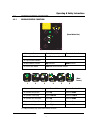
1
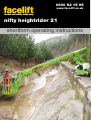
B
0800 52 15 95
www.facelift.co.uk
nifty heightrider 21
shortform operating instructions
SAFETY TIPS
ALWAYS
NEVER
• Inspect your machine before use.
• Use an unsafe machine.
• Check all operations including ground controls.
• Use an access platform to hoist loads like a crane.
• Check ground conditions.
• Overload cage/platform.
• Check clearance from overhead obstructions (power
cables, building projections etc).
• Operate in strong winds (Check manufacturer’s
recommendation).
• Plan your task/job.
• Rest the cage on a structure or object to gain
extra support.
• Use sole boards under your outriggers at all times
regardless of ground conditions.
• Stabilise and level machine before use.
• Wear a safety harness connected to a suitable
anchorage point inside the platform.
• Operate all controls smoothly.
• Warn other people that you are there by means of
flashing lights, sign and cones.
• MAKE SAFETY YOUR No.1 PRIORITY.
• Attach your safety harness to a structure outside of
the platform.
• Throw or drop anything from the platform.
• Use boxes, ladders or stand on handrails to gain additional
height, if you can’t reach, you need a bigger machine.
• Let an untrained person operate the access platform.
• Take unnecessary risks (hospitals and graveyards are
full of dead heroes!)
In the unlikely event that your machine develops a fault
please contact the Facelift Tech Team on 01444 881100
CONTENTS
Regular Machine Checks...............................3
Machine Controls.......................................6
Operating & Safety Instructions.....................5
Emergency Controls..................................10
2
Regular Machine Checks
3.3
PRE-OPERATIONAL SAFETY CHECK SCHEDULES
Before use each day and at the beginning of each shift the aerial platform shall be given a visual
inspection and functional test including, but not limited to, the following:
3.3.1
3.3.2
DAILY SAFETY CHECKS
1)
Check that all labels (decals) are in place and legible.
2)
Visually inspect the machine for damaged or loose components.
3)
Check that batteries are charged (i.e. Charger has a solid green light and a pulsing red light).
4)
Check the fuel level (if applicable).
5)
Check that canopies/covers and guards are in place and secure.
6)
Check that the boom rest switch is operable (if applicable).
7)
Check that control levers are secure and operate freely.
8)
Check that operating buttons and emergency stop buttons function properly.
9)
Check the operation of the emergency hand pump.
10)
Visually inspect all hydraulic hoses and fittings for damage or leaks.
11)
Check that the platform pivot pins and their tag bolts are secure.
12)
Check that the tilt alarm is functioning properly (On a slope of 50 or more the alarm should
sound and drive should be disabled).
13)
Check the operation of the cage weigh system (If fitted). See section 4.5.3 for testing and
verification procedure.
WEEKLY SAFETY CHECKS
1)
Inspect tyres and wheels for damage and wear.
2)
Check that the joystick manipulators are secure.
3)
Check battery fluid levels and specific gravity (after charging) and general condition.
4)
Check hydraulic oil level (ISO Grade 22).
5)
Inspect the engine air filter and clean or replace if necessary.
6)
Inspect hose track for damage or missing parts.
12
3
THIS MACHINE IS NOT INSULATED.
If in doubt, contact the appropriate authorities
2.1.11
On entering the platform ensure that the drop down entry bar is closed afterwards.
2.1.12
Use of an approved safety belt and lanyard, hard hat and appropriate safety clothing is mandatory.
Fasten harness to designated harness securing points within the platform and do not remove until
leaving the platform whilst in the stowed position.
2.1.13
Always remain standing within the platform. Do not attempt to increase your
height or reach by standing and/or climbing on the platform guard rails or any
other object. KEEP YOUR FEET ON THE PLATFORM FLOOR. Do not sit,
stand or climb on the guard rail, mid rail or boom linkage. Use of planks,
ladders or any other devices on the Niftylift for achieving additional height or
reach shall be prohibited.
2.1.14
Do not use the platform levelling system to artificially increase the outreach of the platform. Never
use boards or ladders in the platform to achieve the same result.
2.1.15
Do not use the platform to lift overhanging or bulky items that may exceed the maximum capacity or
carry objects that may increase the wind loading on the platform. (e.g. Notice boards etc.)
2.1.16
The Niftylift shall not be operated from a position on trucks, trailers, railway cars, floating vessels,
scaffolds or similar equipment unless the application is approved in writing by Niftylift Ltd in Great
Britain.
2.1.17
Always check that the area below and around the platform is clear of personnel and obstructions
before lowering or slewing. Care should be taken when slewing out into areas where there may be
passing traffic. Use barriers to control traffic flow or prevent access to the machine.
2.1.18
Stunt driving and horseplay, on or around the Niftylift, shall not be permitted.
2.1.19
When other moving equipment and vehicles are present, special precautions shall be taken to
comply with local ordinances or safety standards established for the work place. Warnings such as,
but not limited to, flags, roped off areas, flashing lights and barricades shall be used.
2.1.20
Before and during driving while the platform is elevated the operator shall maintain a clear
view of the path of travel, maintain a safe distance from obstacles, debris, drop offs,
holes, depressions, ramps and other hazards to ensure safe elevated travel. Maintain a
safe distance from overhead obstacles.
2.1.21
Under all travel conditions the operator shall limit travel speed according to conditions of ground
surface, congestion, visibility, slope, location of personnel and other factors causing hazards of
collision or injury to personnel.
2.1.22
The aerial platform shall not be driven on grades, side slopes or ramps exceeding those for which
the aerial platform is rated by the manufacturer.
2.1.23
It shall be the responsibility of the user to determine the hazard classification of any particular
atmosphere or location. Aerial platforms operated in hazardous locations shall be approved and
suitable for the duty. (See ANSI/NFPA 505-1987 where applicable).
4
Operating & Safety Instructions
2.1.24
The operator shall immediately report to his supervisor any potentially hazardous location(s)
(environment) which become evident during operation.
2.1.25
If an operator encounters any suspected malfunction of the Niftylift or any hazard or potentially
unsafe condition relating to capacity, intended use or safe operation, he shall cease operation of the
Niftylift and request further information as to safe operation from his management, or owner, dealer
or manufacturer before further operation of the Niftylift.
2.1.26
The operator shall immediately report to his superior any problems or malfunctions of the Niftylift,
which becomes evident during operation. Any problems or malfunctions that affect the safety of
operation shall be repaired prior to continued use.
2.1.27
The boom and platform of the Niftylift shall not be used to jack the wheels off the ground.
2.1.28
The Niftylift shall not be used as a crane.
2.1.29
The Niftylift shall not be positioned against another object to steady the platform.
2.1.30
Care should be taken to prevent rope, electric cords and hoses from becoming entangled in the
aerial platform.
2.1.31
Batteries shall be recharged in a well-ventilated area free of flame, sparks or other hazards, which
may cause explosion. Highly explosive hydrogen gas is produced during the charging process.
2.1.32
When checking electrolyte levels great care should be taken to protect eyes, skin and clothing.
Battery acid is highly corrosive and protective glasses and clothing is recommended.
2.1.33
If the platform or elevating assembly becomes caught, snagged or otherwise prevented from normal
motion by adjacent structure or other obstacles, such that control reversal does not free the
platform, all personnel shall be removed from the platform safely before attempts are made to free
the platform using ground controls.
2.1.34
When the machine is not in use always stow the booms correctly.
NEVER LEAVE THE KEYS IN THE MACHINE, if it is to be left for any
period of time. Use wheel chocks if leaving on an incline.
2.1.35
The engine must be shut down while fuel tanks are being filled. Fuelling must be done in a wellventilated area free of flame, sparks or any other hazard that may cause fire or explosion. PETROL
(GASOLINE), LIQUID PROPANE AND DIESEL FUELS ARE FLAMMABLE.
2.1.36
NEVER START THE NIFTYLIFT IF YOU SMELL PETROL (GASOLINE),
LIQUID PROPANE OR DIESEL FUEL. THESE FUELS ARE HIGHLY
FLAMMABLE
2.1.37
The operator shall implement means provided to protect against use by unauthorised persons.
2.1.38
Never remove anything that may affect the stability of the machine such as, but not limited
to, batteries, covers, engines, tyres or ballast.
9
5
Operating & Safety Instructions
4.2
GROUND CONTROL OPERATION
4.2.1
GROUND CONTROL FUNCTIONS
1
0
3
2
(Base Button Box)
0
4
5
P16752/01
1 Emergency Stop
Push to Stop machine
Turn clockwise to Release
2 Diesel Glow/Start Selector
Turn Clockwise – Glow, Off and Start posistions
3 Cage Overload Indicator
4 Base/Platform Selector
Up for Booms
Down for Base
5 Green Power Button
Push and hold to activate machine
P14018/001
(Base
Levers)
1
2
3
4
5
6
1 Operates Platform Levelling
Up for Forward **
Down for Backward **
2 Operates the Flyboom
Up for Up
Down for Down
3 Operates Telescoping
Up for Tele Out
Down for Tele In
4 Operates the Link Booms
Up for Up
Down for Down
5 Operates the Upper Boom
Up for Up
Down for Down
6 Operates Swing
Up for Right
Down for Left
** Platform levelling only active when booms are down
5
6
Operating & Safety Instructions
4.2.2
OPERATION
ALWAYS ALLOW THE ENGINE TO WARM UP BEFORE OPERATING.
ALL MODELS
1)
Ensure all red emergency stops are out.
2)
Turn Base/Platform selector at ground control station to Ground (Clockwise).
DIESEL ENGINE
3)
COLD ENGINE: - turn the Diesel Glow/Start selector to the Glow position (anti-clockwise).
This engages the glow plug pre-heat system. Hold for 3-5 seconds then turn the key to the
Start position (fully clockwise) and the engine will fire.
4)
WARM ENGINE: - turn the Diesel Glow/Start selector to the Start position (clockwise) and
the engine will fire.
ALL MODELS
5)
Push and hold green power button on the base control box.
6)
Select a function and operate the appropriate hydraulic lever in full accordance with
manufacturers operating and safety manual.
7)
To return control to the platform turn the Base/Platform selector to the Platform position
(anti-clockwise).
8)
When not in use return machine to stowed position, turn the Base/Platform selector to
centre Off position, remove key and chock wheels.
EMERGENCY PROCEDURES
9)
Push in red emergency stop to shut down all functions.
10)
In the event that the controls fail or the operator becomes incapacitated the booms can be
operated by using the hand pump which is located under the canopy next to the base
controls. To operate:
a)
Check the selector under the middle bonnet is turned to booms.
b)
Move and hold lever to be operated.
c)
Use hand pump lever to move machine.
d)
Release control lever to halt machine movement
26
7
Operating & Safety Instructions
4.3
PLATFORM CONTROL OPERATION
4.3.1
PLATFORM CONTROL FUNCTIONS
1
+ -
2
3
5
6
4
(Cage Button Box)
0 I
9
8
7
P14015/004
1 Emergency Stop
Push to Stop machine
2 Horn
Push to sound
Turn clockwise to Release
3 Battery Charge indicator
4 Cage Overload Indicator
5 Diesel Glow
Push to Glow Engine
6 Drive Speed Selector
Turn Clockwise - Slow, Fast and Rough terrain modes
7 Green Power Button
Push and hold to activate machine
8 On/Off & Diesel Start
9 Joystick
P14020/001
(Cage Levers)
1
2
3
4
5
6
1 Operates Platform Rotation
Up for Clockwise
Right for Anti-Clockwise
2 Operates the Flyboom
Up for Up
Down for Down
3 Operates Telescoping
Up for Tele-In
Down for Tele-Out
4 Operates the Link Booms
Up for Up
Down for Down
5 Operates the Upper Boom
Up for Up
Down for Down
6 Operates Swing
Left for Left
Right for Right
23
8
Operating & Safety Instructions
4.3.2
OPERATION
NEVER START THE NIFTYLIFT IF YOU SMELL PETROL (GASOLINE), LIQUID
PROPANE OR DIESEL. THESE FUELS ARE FLAMMABLE.
BEFORE OPERATING THE NIFTYLIFT ENSURE THAT EACH OPERATOR HAS
READ AND FULLY UNDERSTOOD THE OPERATING MANUAL. FAILURE TO
DO SO MAY RESULT IN DEATH OR SERIOUS INJURY.
ALL MODELS
1)
Ensure all red emergency stops are out.
2)
Turn the Base/Platform selector at the ground control station to Platform (anti-clockwise).
DIESEL ENGINE
6)
COLD ENGINE: - push the Diesel Glow button to engage the glow plug pre-heat system.
Hold for 3-5 seconds then turn the On/Off Diesel Start selector to the Start position
(clockwise) and the engine will fire.
7)
WARM ENGINE: - turn the On/Off Diesel Start selector to the Start position (clockwise)
and the engine will fire.
ALL MODELS
8)
Depress the footswitch (if available) or push and hold green power button on the platform
control box.
9)
Select a function and operate the hydraulic control levers in full accordance with
manufacturers operating and safety manual.
10)
To return control to the base turn Base/Platform selector to the Base position (clockwise).
11)
When not in use return booms to the stowed position. Turn the Base/Platform selector to
the centre Off position, remove key and chock wheels.
ALWAYS ENSURE THE AERIAL PLATFORM IS ON A FIRM LEVEL SURFACE
AND THE AREA IS FREE OF ANY OVERHEAD OBSTRUCTIONS.
ENGAGING THE RED EMERGENCY STOP BUTTON WILL SHUT DOWN THE
ENGINE, AND THE ELECTRIC CIRCUIT PREVENTING OPERATION OF ANY
FUNCTION.
9
Operating & Safety Instructions
4.4
DRIVING CONTROLS
DO NOT OPERATE THE NIFTYLIFT WHILST ELEVATED UNLESS ON A FIRM,
LEVEL SURFACE FREE FROM ANY POSSIBLE OBSTRUCTIONS OR
HAZARDS BOTH AT GROUND LEVEL AND OVERHEAD.
1)
2)
3)
Check proposed route for possible hazards, obstructions and personnel.
Depress switch located on the front of the joystick.
Use the Drive Speed selector on the platform control station to determine speed.
Low Drive (Tortoise) - gives low speed and low engine revs..
High Drive (Hare) - gives high speed and high engine revs.
RT Drive (Rough Terrain) - gives low speed and high engine revs.
N.B. High Drive is only available when the booms are in the stowed position. The HR21 will
default Low Drive speed whenever the booms are elevated.
4)
Select drive joystick from the platform control box.
A.
B.
Up for FORWARD
Down for REVERSE
Steering is controlled by the rocker-switch button on the top of the joystick
C.
D.
Left for STEER LEFT
Right for STEER RIGHT
The driving horn is activated by the button on the front of the joystick and there is also a
separate horn button on the platform controls for use when the drive and boom controls are
switched off.
5)
All control levers give a fully proportional response therefore the more the lever is moved
away from the centre Off position the faster the function will become.
6)
Maximum drive speed is only attainable when all booms are fully stowed and the Drive
Speed selector is in the High Drive (Hare) position.
7)
When driving with the booms fully stowed, the Tilt Alarm is bypassed to allow the Niftylift to
be driven in areas where the slope exceeds the five-degree working limit. In normal operation
the drive is therefore unaffected when driven onto a slope in excess of five degrees, until the
booms are raised, whereupon the drive would be disabled and the tilt alarm sounds
continuously.
Under no circumstances should any Height Rider 21 series machine be driven on slopes
exceeding the gradeability in the general specification.
8)
ALL NIFTYLIFTS ARE FITTED WITH A TILT ALARM - PRE-SET IN THE
FACTORY. ONCE ENERGISED THE NIFTYLIFT WILL LOSE ALL POWER TO
DRIVE FUNCTIONS AND A LOUD AUDIBLE ALARM WILL BE ACTIVATED.
TO DE-ACTIVATE, LOWER THE BOOMS FULLY TO STOWED POSITION AND
RE-POSITION BASE ON FIRM, LEVEL GROUND.
IF ALARM SOUNDS - DESCEND IMMEDIATELY AND RE-LEVEL MACHINE
BASE.
10
Operating & Safety Instructions
5
Emergency Controls
5.1
GENERAL
CHECKING THE OPERATION OF THE EMERGENCY CONTROLS EVERY DAY
AND/OR BEFORE EACH SHIFT IS AN ESSENTIAL PART OF THE OPERATOR'S
DUTIES
The operator and all ground personnel must be thoroughly familiar with the location and operation
of the EMERGENCY CONTROLS.
5.2
IN THE EVENT OF AN INCAPACITATED OPERATOR
Turn the Base/Platform selector at ground control station to ground (clockwise). Lower on
ground controls as detailed under Section 4.2 Ground Control Operation.
5.3
IN THE EVENT OF MACHINE FAILURE
If all machine power is lost, the Emergency Hand pump can be used to provide the hydraulic
power to manoeuvre the machine. Lower platform using hand lever controls at ground control
station.
Note: If the machine is fitted with a cage overload system, and the cage comes into contact with a
fixed object whilst operating at height, this would be detected as an overload condition. All power
to the machine controls would be lost, requiring the machine to be recovered using the Emergency
Hand Pump. It is sufficient for the cage to be manoeuvred away from the collision point to re-set
the cage weigh mechanism, thereby restoring normal machine operation. The cage could then be
brought down using the controls as described previously.
Opening the nearside machine canopy reveals the ground controls, plus the dedicated hydraulics for
the Emergency recovery of the machine.
Primarily there are two emergency hand pumps, one for the boom functions only, mounted
separately and adjacent to the ground control valve block. The second hand pump is specifically
for the drive system and is incorporated into the Drive Control Valve.
33
11
Operating & Safety Instructions
5.4
BOOM CONTROLS
On opening the canopy cover, the two hand pump handles are revealed. The black handle with a
red handgrip fits the Boom hand pump. Remove the handle and fit this to the appropriate pump.
When the handle is actuated, hydraulic flow is generated and will be supplied directly to the ground
control valve block. Operating the ground control lever will permit the machine to be manoeuvred
by the ground personnel.
If desired, the Cage operator can hold the appropriate lever to manoeuvre the machine, whilst a
ground operative provides the motive power using the emergency hand pump. When not in use,
the handle should be stowed back in its clips.
5.5
DRIVE CONTROLS
Situated to the side of the ground controls is found the Drive Control Valve. This valve block
controls the drive, brakes and emergency controls for all of the drive functions.
Under normal operation the brake release knob should be closed. To do this, turn the red knob fully
clockwise to close that circuit. When the machine is driving, the brake tell-tale will ‘pop’ out to
indicate that brake pressure is being generated. The silver hand pump handle fits the integral
pump, which is now ready for use.
12
Operating & Safety Instructions
5.6
TOWING
To tow the machine it is necessary to bypass the parking brakes. First, ensure that the machine is
restrained against running away, i.e. positioned on a flat, level surface or adequately chocked on
two or more wheels in both directions. Moving the machine must not be attempted until adequate
means to restrain it from running away are in place.
Fit the hand pump handle to the drive control valve pump. Push and hold down the brake release
actuator, whilst pumping the handle. When brake pressure is generated, the brake ‘tell-tale’- will
indicate this by ‘popping’ out of the housing.
The brakes are now bypassed and the machine is capable of being towed at a low speed. The tow
valve, integrated into the drive control valve, is piloted open at the same time as the brakes are
released, and permits this.
To re-set the parking brakes, the brake release knob should be opened. This is the red knob on the
side of the Drive Control Valve. Opening this knob allows the brake pressure to dissipate from the
bypass circuit, re-setting the parking brakes and de-energizing the tow valve. The machine will now
lock the wheels and deny any attempt at towing.
35
13
facelift
0800 072 55 72
www.facelift.co.uk
access and safety made easy
operator training centre
When hiring access
equipment we strongly
recommend taking
advantage of one of our
operator training courses.
As Facelift is an accreditied IPAF (Independent Powered
Access Federation) training centre you can be sure that your
staff will be trained to a high standard and receive an
internationally recognised qualification.
Courses can take place on your own premises or at one of
our training centres, situated in Hickstead, Iver, Southampton,
Liverpool, Birmingham and Basildon.
We can train your personnel on any
of the following equipment:
(1a) Static Vertical
Vertical Personnel Platform (static)
(1b) Static Boom
Self Propelled Boom with outriggers, Trailer/Push
around, Vehicle Mounted Platform up to 26m and
Vehicle Mounted Platform over 26m*
(3a) Mobile Vertical
Scissor Lifts, Vertical Personnel Platform (mobile)
(3b) Mobile Boom
Self Propelled Boom
Specialist Machines
Spider*
The one day course covers site safety, practical demonstration,
sole usage, site risks and includes a theory test
* Two day courses are required for the Spider and Vehicle
Mounted Platforms over 26m
Successful candidates are issued with the IPAF PAL card,
widely accepted by both the CITB and Health And Safety
Executive.
We also run the following courses:
For further information or to arrange
a training course contact us today on:
0800 072 55 72 or [email protected]
MEWPs for Managers
Loading and Unloading
Harness Use and Inspection
PASMA Aluminium Tower Training
BLMA Ladder Training