1
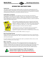
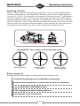
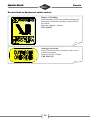
Operators Manual EUROTEL Models ET32LF, ET36LF and ET38LF For Eurotel models from 2009 Last revised 1st December 2009 Contents Operators Manual CONTENTS Daily Check List Page 2 EMERGENCY OPERATION Page 3 Introduction Page 4 Safety Page 5 Operational safety Page 6 Operating Instructions Page 9 Emergency Operation Page 20 Safety Inspection Page 26 General Specifications Page 31 Decals Page 39 Warranty Page 48 Index Page 49 It is the responsibility of the operator to be familiar with all aspects of the machine and manual. 1 Check List Operators Manual DAILY CHECK LIST Check engine oil and fluids, also ensure that the battery is sound Check condition and correct pressure of tyres Check all lamps / warning beacons for correct operation Check the vehicle handbrake for correct operation Ensure that all emergency controls operate correctly Ensure that the Versalift is correctly stowed for travelling Check that all warning lights are operational Know vehicle travel height Visually check all critical fasteners and critical welds Check hydraulic lines for integrity and signs of wear Check for oil leaks and confirm the hydraulic oil level Ensure that there are no loose objects, or potential hazards Confirm operation of all controls and control selector, from ground Check levelling systems for damage, wear or foreign objects Decals should all be present and legible Check for evidence of lubrication regime Check Emergency Motor for operation Please also refer to „Safety Inspection‟ section, from page 26. 2 Emergency Operation Operators Manual EMERGENCY OPERATION In the event that the operator in the bucket has become unable to operate the Versalift, ground personnel will need to take control of the machine, by selecting the lower controls function, using the Control Selector Switch (as illustrated), located on the pedestal. VDL 10 45-2 16 Press to STOP Twist to RELEASE VDL 10 45-2 16 Recover Operator Located on ground controls Switch to Lower Controls Use Lower Controls Located on pedestal, if key is missing refer to page 22 for manual emergency operation Located on pedestal Assuming engine has been stopped or stalled, the emergency motor can be used by the use of both buttons „A‟ and „B‟ simultaneously, followed by the appropriate function button. Should the engine be still running and it is safe to do so, the ground controls can be operated without the need for emergency motor, button „B‟ Emergency STOP Rotate Left 5 5 Rotate Right Greyed out icons are not applicable to the ET-LF machines. Telescope IN 3 2 Flyboom Boom DOWN 4 1 Engine STOP EMERGENCY motor B A GO button Press simultaneously Do not operate the emergency motor for periods of over 30 seconds, should recovery require longer, pause for a few seconds before re-commencing. Should the emergency motor not be operating or circumstances prevent its use, refer to MANUAL recovery from page 22. 3 Introduction Operators Manual INTRODUCTION This Versalift aerial device has been designed and engineered to conveniently place personnel at work stations at height above the ground. Full controls at the platform and the complete freedom of boom movements make the Versalift a truly flexible and functional work platform. This manual is furnished to provide practical and essential information for efficient operation of the equipment and must at all times remain with the equipment. A copy of the service and parts manual for this machine was presented to the original customer at the time of manufacture and this deals with the regular maintenance and servicing of the equipment. Should additional copies of any of the manuals be required these are available on request (charges may apply). Proper operation of this Versalift is the responsibility of the operator. Therefore it is important to read and understand this manual before attempting to operate this aerial device. A copy of this Operators Manual MUST ALWAYS remain with the equipment, in accordance with local regulations. This is NOT maintenance free equipment Contact Service and Customer Support, for more information; Versalift Distributors (UK) Ltd 1 Altendiez Way, Latimer Park, Burton Latimer, Northamptonshire, NN15 5YT. Tel - 01536 721 010 Fax - 01536 721 111 Email - [email protected] www.versalift.co.uk DANGER WARNING 4 NOTE Safety Operators Manual SAFETY Only properly trained operators are qualified to operate the Versalift aerial lift as per local regulations. Operator training shall include complete instruction and understanding of this manual, employer‟s work rules and all related governmental regulations. Prior to operation from the platform the machine must be operating properly, inspected and maintained in accordance with the manufacturer‟s instructions. All safety signs, guards and covers must be in place and in proper condition. An untrained or careless operator subjects themselves and others to death or serious injury. There are three key risks associated with operating an aerial lift: Electrocution can be caused by operating too close to power lines, resulting in death or serious injury. Injury caused by falling as a result of equipment failure, not wearing a harness, or performing an unsafe manoeuvre. There is a potential risk of crushing from being trapped beneath overhead structures. No operating manual can address every conceivable operating hazard for the operator; therefore the prevention of accidents is greatly dependent on good judgement and common sense on the part of the operator. This attitude of safety is very important to you, the operator. Practice anticipating accidents and operating hazards. Then determine a corrective course of action to respond to the situation. This habit will sharpen your safety awareness, quicken your reaction time and prevent many accidents. THINK SAFETY! To help facilitate the safe operation of this equipment there are a number of decals that indicate hazards and give instructions on safe use, it is important that these are in situ. Decals Decals are installed at numerous locations on the Versalift in an effort to warn all personnel of the potential hazards during the use and operation of the Versalift. It is important that the operator, as well as any ground personnel read and understand the information on the decals. If any decal is defaced or illegible or lost, they MUST be replaced. A pictorial summary of all the safety critical decals is illustrated to the rear of this manual from pages 39 to 47, for easy reference including part numbers for when ordering replacements. 5 Operational Safety Operators Manual OPERATIONAL SAFETY Always deploy stabilisers/jacks, when fitted and check correct tyre pressure to ensure maximum vehicle stability. Always wear a safety harness connected via a short lanyard to the designated anchor on the Versalift equipment. Do NOT park on a hill, unless absolutely necessary. Use of wheel chocks and application of handbrake are essential. Watch the booms to make sure they are clear of the vehicle and any fixed or moving obstructions or hazards. Maintain safe clearance to electrical power lines & equipment. Ensure correct stowage of the booms, before driving vehicle. DO NOT EXCEED the SWL or maximum vehicle payload (GVW) as shown on data plate and decals. Avoid working beneath structures, due to risk of crushing. ONLY stand on the floor of the personnel bucket and do not climb out or step up within the bucket. Always latch the door or safety bar on the personnel bucket Avoid parking on soft or unstable surfaces. DO NOT operate in windy conditions greater than 12.5 m/s. DO NOT use the Versalift as a crane. DO NOT take equipment into the bucket (work platform) that could increase wind resistance, such as notice board. 6 Operational Safety Operators Manual Operating in Windy Conditions The Versalift equipment should not be used in high wind conditions, such as when large tree branches are in motion, whistling can be heard in telephone wires, or umbrellas hard to use. Max Operational Wind Speed 12.5 m/s Should wind speeds be less than this but still noticeable, then extra care should be taken in these conditions, to avoid potential incidents. All machines have a rated wind speed at which they can work safely and as such all operators must have an anemometer to assess wind speed. For the majority of Versalift machines this is 12.5 metres per second (24 knots) that is equal to 28mph. At any wind speed higher than this, NO attempt should be made to raise or operate the platform. Please note that the wind speed will vary according to the height above ground level. In level open areas it may increase by as much as 50% at 20m above ground level. Due allowance must be made for this if measuring wind speed at ground level before elevating the Versalift MEWP. When there are buildings, trees or any other obstructions, wind speed can be increased by the aerodynamic effects on the wind. It is essential that in appropriate circumstances that wind speed is measured from the personnel bucket of the Versalift and not from the ground, or adjacent buildings. Do not take equipment or tools in to the bucket that have a large surface area, such as signs as this can catch the wind causing a hazard and affect the safe performance of the Versalift. Safety Law / LOLER Certification of work equipment, including MEWPs is covered by The Lifting Operations and Lifting Equipment Regulations (LOLER). These regulations give legal effect to previous HSE recommendations and require every MEWP in use to be covered by a currently valid evidence of “thorough examination”. Many workplaces now require a Report of “Thorough Examination” to be provided with the equipment. This LOLER certificate is valid for 6months and MUST be up to date. 7 Operational Safety Operators Manual Working under Overhead Structures Always take great care when operating this machine beneath overhead structures, as serious injuries can result from inappropriate use. It is recommended that the control selector switch on the upper controls is returned to „O‟ when not in use. To prevent the risk of inadvertently becoming trapped always keep clear of the sides of the personnel bucket and operate the booms slowly and carefully. DO NOT LEAN OUT. It is safer to manoeuvre the personnel bucket in to the appropriate position, rather than stretch and risk personal injury. Overhead High Voltage Lines Most overhead electric lines are un-insulated and usually carry high voltage electricity, up to 400,000 volts. Unless you are operating a certified Insulated Aerial Device (IAD) then safe distances must be maintained at all times, as a simple fibreglass bucket will NOT protect you. Not all sites are controlled and the operator must always be aware of the dangers of overhead electric lines and equipment. Many fatal accidents have occurred due to some part of a machine touching or even coming close to overhead lines. A minimum safe distance must always be kept between the overhead lines and the closest point of the MEWP when fully extended. This distance is 15m with overhead lines mounted on steel towers and 9m with lines mounted on poles of wood, concrete or steel. These distances are measured horizontally at ground level from a position vertically below the outermost conductor at the tower or pole position. 15m 9m 8 Operating Instructions Operators Manual OPERATING INSTRUCTIONS Introduction This chapter provides the operator and the ground crew with some recommended aerial lift operating procedures, descriptions of the controls and detailed operating information about the controls at each control station. The operator and the ground crew are responsible for knowing and applying this information to the situations that arise on the job. Qualifications to Operate Only properly trained operators are qualified to operate this aerial lift, in the UK this is predominately a „Powered Access Licence‟ (PAL) to cover „Static Boom 1b‟ type equipment, (this category used to be known as VMP 26). Details of the Powered Access Licence can be obtained through the International Powered Access Federation‟ (IPAF), or contact Versalift for further details and training options. Safety legislation demands that the operator is properly trained in the operation of work equipment which includes „Mobile Elevating Work platforms‟ (MEWP). The IPAF „PAL‟ card is proof of this and provides evidence of competence and history. It is also essential that operators familiarise themselves with their particular machine. A Powered Access Licence Card issued by IPAF carries all the key facts companies need to know, it tells site management which equipment an operator has been trained to handle safely and efficiently. Ensure the equipment itself has a valid LOLER certificate (see page 7). Daily Operational Checks Ensure that the daily checks are performed before leaving for the work site, to ensure that the equipment is fully operational and safe. These are detailed at the front of this manual on page 2 and can be photocopied. It is in the operators‟ best interest that this daily check is performed as failure to do so could result in an accident and or serious injury. When Travelling Ensure that the „Power Take Off‟ (PTO) is disengaged and that all warning lights show a condition suitable for driving. Drive at a reasonable speed for given road conditions and situations, remember that you are effectively driving a heavily laden vehicle with a high centre of gravity, so excessive speed will affect the vehicles cornering and braking performance. Avoid potholes and violent manoeuvres which may adversely stress the Versalift structure. Please note that all installations are STRICTLY designed for operation within the vehicles GVW. A spare payload decal is provided to ensure compliance with this safety critical measure. 9 Operating Instructions Operators Manual Positioning of Vehicle Park the vehicle on firm level ground whenever possible as this is the most stable method of operation, with freedom to work within the full working envelope of the Versalift equipment (see pages 32, 34 & 36). Do not operate the equipment on slopes greater than 5o (approximately 1m rise in 12m) left to right or 10o front to rear, as any slope will reduce the vehicles stability and places additional stresses on the equipment. An inclinometer is provided to show when the vehicle is within the 5o and 10o slope requirement. Should it be necessary to work on an incline, extra precautions are required for increased stability, such as chocking the wheels and operate by pointing the vehicle either up or down a slope as illustrated, rather than across it. o MAX 10o MAX 5 Maximum Permissible slope with outriggers and wheel chocks INCLINOMETER - Slope condition indicated by bubble position Operating slope level Maximum operating slope ‘lateral’ Maximum operating slope ‘longitudinal’ Before Leaving Cab Assuming that the vehicles engine is running perform the following checks; Check that the parking brake / handbrake is fully applied. Ensure vehicle transmission is in NEUTRAL or PARK for automatics Turn on BEACONS / LIGHTBARS if fitted PTO is engaged and amber warning light is on Leave ignition in the RUN position 10 Operating Instructions Operators Manual After Leaving Cab Check the Versalift equipment for damage which may have occurred during transit, this should include the personnel bucket (work platform) for cracks. Also verify that the weather conditions are compatible with safe working, see „Operating in Windy Conditions‟ on page 7. It is strongly recommended to chock the wheels of the vehicle, as the handbrake systems on some vehicles apply the brakes by locking the drive shaft behind the transmission. Thus should the weight be reduced from one or both of the rear wheels, by the position of the lift, the vehicles differential may disengage and reduce the rolling resistance of the vehicle. In the case of jackless operation models, wheel chocks MUST be used. Use of Jacks (Stabilisers) and Setting Up If the unit is equipped with stabilisers, they can be used at this time. In most cases the controls are located in the cab, but can also be found on the upper controls. Ensure that the stabilisers have a clear path to ground with no obstructions such as kerb, manhole cover, gullies, etc. Be aware of any changes in ground conditions through rainfall. Should the ground be too soft for the Jacks to be effective, use spreader pads on the ground to increase the bearing area. The jacks should only be deployed until the bulge has been taken out of the tyres. Please note that the vehicle tyres are NOT to be lifted off the ground when the platform is used. If the vehicle is PARKED ON SLOPING GROUND so that one side of the vehicle is lower than the other, extend the low side stabilisers first, make sure firm contact is made with the ground and avoid tilting the vehicle even more to the low side as the high side Jacks is lowered. If one or both stabilisers are not fully extended, spread is reduced, compromising the stability of the equipment. The stability of the vehicle is dependent on the GVW, firmness of the ground, slope of the ground, weight in the platform and the stabilisers spread (if so equipped). These factors are widely variable, so caution must be used while learning what the unit can safely handle. Set up adequate cones or barricades to mark the boundaries of the work site and alert pedestrians and motorists to the hazard. Please pay particular attention to the rotating turret, as it can project outside the width of the van when rotated and potentially in to the path of traffic. 11 10 45-2 16 Operating Instructions Operators Manual Aerial Lift Operations The following emphasises some overall operating practices and concerns for aerial lift operation and is written in an order of probable use while operating from the ground, then at the platform and close to energised conductors. <1 20k g Only use the ground controls when the platform operator gives permission or is incapacitated. Always have a clear sight of the platform or have someone responsible to signal platform movements. In extremely cold weather, ensure that the engine is at full operating temperature before using the platform. For operating in colder climates please refer to hydraulic system inspection on page 30 of this manual. PAR T N O. VDL 10 88 -4 2 If the Versalift has not been used for an extended period of time, then the lift must be operated from the lower controls through its full range of motion several times before an operator enters the platform and uses the machine. This procedure allows the operator to confirm the lift is operating correctly and to purge any air that may have become trapped in the hydraulic system. Be aware of the operating environment and existence of overhead power lines (see page 8), before commencing work. Control Selection Prior to commencing operation of the Versalift equipment hydraulic power must be switched to the appropriate action required, which for the purposes of this manual the first requirement is to deploy the stabilisers. The control selector is located to the side of the grey control box mounted to the pedestal and selection can be directed to either the upper or lower controls, denoted by the illustration of an operator in the personnel bucket (upper) or a van (lower) respectively. The control selector is a two position switch that is lockable to prevent unauthorised use and is designed so that the Lower and Upper controls cannot be operated simultaneously. VDL 10 45-2 16 A Normal operational position, as provides power to the upper controls, isolating lower controls. B Lower position provides power to the lower (ground) controls and for deployment of the stabilisers. Also facilitates EMERGENCY OPERATION from ground. 12 Operating Instructions Operators Manual Cab Controls From the Cab Control Panel the Versalift can be powered up, the stabilisers deployed and control of the Boom selected. The facia should look similar to the diagram below and is usually located to the dashboard in clear line of sight. If not already done so, with the engine running engage the PTO by turning switch 5 to IN, it is good practice to have the clutch depressed at this point and to slowly release it when a change in engine idle speed indicates that the PTO is engaged. The PTO warning lamp 7 should now be lit to indicate it is working correctly. Turn on the warning beacons. 1 2 3 4 5 Typical Cab Control Panel 1. 2. 3. 4. 5. 6 7 6. 7. Left Hand stabiliser/jacks operation Right Hand stabiliser/jacks operation Jacks deployed OK light Jacks or Booms selector switch PTO selector switch see note Jacks not stowed correctly, warning light PTO is engaged light PTO Switch Transmission PTO‟s such as found on the Iveco Daily and Mercedes Sprinter, have a separate manufacturers PTO selector switch and can usually be found beside the steering column and can typically be identified by the symbol illustrated. Operation remains same as above. PTO Do not try to disengage the PTO pump when the platform is in use, or with the stabilisers down. The above panel represents the most common cab controls, with the Jacks/Boom interlock operated from within the cab. For „Extended Outreach‟ load cell models, the Jacks/Boom interlock is located on the upper controls to the personnel bucket. 13 Operating Instructions Operators Manual Jacks Deployment Ensure that Jacks/Booms selector switch (4) of the cab controls is set to JACKS. The Jacks/Boom selector switch enables control of either the Jacks or the Boom. The Boom will not operate until the Jacks are deployed; this feature is called the Jacks/Boom interlock. The Jacks/Boom interlock is a safety feature that prevents the lift from being operated until the Jacks are properly extended. The interlock also prevents the Jacks from being retracted before the lift is stowed. This option is particularly useful in keeping unauthorised personnel from operating the Jacks while an operator is in the platform. The Interlock is in the form of a microswitch being made when a male and female locating system engages under the platform when it is stowed. If your vehicle is fitted with Beacons or Warning lights, make sure that they are ON now. The LH Jacks and RH Jacks switches operate independently and are switched to the DOWN position in turn. As soon as one Jack breaks the STOWED safety limit switch, the JACKS NOT STOWED lamp is lit and remains in this state until both Jacks are back in the STOWED position. When both the Jacks are fully deployed, the green JACKS OK lamp is lit. The PTO pump switch should be left in the IN position while the platform is being operated. When you have finished working with the platform, the Booms should be stowed, the Jacks fully stowed and the PTO pump switched to the OUT position. Remove the chocks. Ensure that the JACKS OK indicator is not lit and that all other lights are extinguished and that no BUZZERS are sounding. Return Jacks / Booms interlock selector switch to booms, exit cab and put control selector switch to either Upper or Lower control. You are now set to operate the Versalift equipment. Harness Safety regulations require the operator to be secured with a personnel restraint system to the lift. The lanyard shall be attached to the safety harness and the other end connected to an identified anchor point located on the personnel bucket. Never operate aerial equipment without wearing an approved personnel restraint system attached to the specified anchor point. Failure to properly secure the harness and lanyard can result in death or serious injury in the event of a fall from the platform. Firstly, let‟s deal with operation from the lower controls. 14 Operating Instructions Operators Manual Lower Controls From the lower hand held controls, full manipulation of the Boom and personnel bucket is possible, either on normal or emergency power, as long as the Control Selector is set to lower controls (B), as described on page 12. 2 7 4 Greyed out icons are not applicable to the ET-LF machines. 8 3 5 1 6 1. 2. 3. 4. 5. Outer Boom – Raise/Lower Flyboom – Raise/Lower Inner Boom – Telescope IN/OUT Slewing (Rotation) – CW/CCW Engine Start/Stop 9 6. 7. 8. 9. Emergency Motor Emergency STOP Bucket Levelling – Deactivated# GO Button – Keep Pressed Never reverse lift motions with a sudden reversal of the control switch. Allow the boom to stop first and then move the boom in the opposite direction. Avoid reaching the end of the boom range at excessive speeds, as structural damage or instability may result. To operate the lower controls the GO button (9) must always be depressed and each function can then be operated as required, ensuring that you have clear site of the Boom and personnel bucket at all times by utilising the wander lead and standing clear of the vehicle. # - The bucket levelling button has been deactivated to prevent unauthorised use in accordance with local HSE regulations, but is useful for cleaning and personnel evacuation in the case of an emergency. This switch has been repositioned INSIDE the unit and is accessed by removing the facia panel. 15 Operating Instructions Operators Manual Upper Controls From the upper controls, full speed controlled manipulation of the Boom and personnel bucket is possible, either on normal or emergency power, as long as the Control Selector on the pedestal is set to upper controls (A), as described on page 12. Rotating the boom selector switch (1) determines which function is to be controlled, followed by the movement of the self centring joystick (2) will move the platform in that direction, at the speed determined by the movement of the joystick, by pulling up on the dead man switch first. Platform movement stops when the joystick returns to the neutral position or when the extent of travel is reached, tripping a micro-switch in which case only movement in the opposite direction is possible. Return Boom Selector Switch to the „O‟ position when Booms are not in use to reduce the likelihood of human error. A B EMERGEN C 4 EMERGENC D 3 1 2 6 Outer Boom Raise / Lower Inner Boom Telescope in/out Flyboom Raise / Lower Standard Features: 1. 2. 3. 4. 5. 6. 5 Slewing (rotation) Left / Right Optional features: Boom selector switch Joystick Emergency motor EMERGENCY STOP Bucket levelling Engine STOP/START A. B. C. D. Load cell 2 man or 1 man operation Jacks from bucket n/s or o/s Jacks Operation Bucket rotation O O „Extended Outreach‟ and „Street Lighting‟ WARNING:equipped versions. R switch to 0 wh 16 WARNING:- Ret switch to 0 when Operating Instructions Operators Manual Personnel Bucket (Work Platform) Levelling To operate the bucket levelling function (5), you will need to put the boom selector switch to the „O’ position first, operate the switch in the direction required first then operate the joystick to carry out the function. Engine Start/Stop The vehicle ignition must be in the START position before the switch can be operated. The engine START / STOP control (6) is operated by a three-position toggle switch labelled with an engine‟s symbol at the upper controls. When operated it activates the engine starter or cuts the engine ignition. The engine start/stop function will work at any time except when the Emergency Stop Function (4) is operated and remains un-released. To START the engine from the upper controls, place the engine toggle in the START position (symbol of a tick) and hold the toggle in that position until the engine starts. Release the toggle and allow it to return to the centred or neutral position. To STOP the engine from the upper controls, hold the engine toggle to the STOP position (symbol of a cross) until the engine has stopped. Release the toggle and allow it to return to the centred or neutral position. The vehicle transmission MUST be in neutral /park before using engine start/stop, otherwise this can cause movement which can destabilise the Versalift and risk serious injury. Emergency Stop Button The Emergency Stop function (4) is controlled by a red mushroom control button with yellow background. To stop the lift in an emergency, push the button down. This kills the vehicle engine and removes power from all lower control switches. This button remains in the STOP position until twisted clockwise to release. Use the engine Start/Stop to regain operation. EMERGENCY MOTOR OPERATION In case of vehicle engine or hydraulic pump failure it is possible to use the Emergency Motor Switch function (3) identified by an „E‟ symbol and selecting the required boom function, operate emergency motor switch and operate joystick to carry out these functions. The emergency motor should not be operated for longer than 30 Seconds continuously, as continuous use drains the vehicle battery and damages (over heats) the emergency motor. To turn off the emergency power, release the emergency switch. Emergency stop switch is controlled by a red mushroom control button. To STOP the platform in an emergency, push the button down. This stops the vehicle engine and removes all power from the platform controls. This button remains in the stop position until twisted clockwise to release. Full emergency operation instructions can be found from page 20. 17 Operating Instructions Operators Manual SWL Load Cell (if fitted) This option ensures that the Versalift cannot be used should the SWL of 200kg be exceeded and does not interfere with the operation of the machine, other than prevent it‟s use in an unsafe overload condition. This feature allows slightly greater operational characteristics and performance. Load Cell and Jacks / stabilisers from Bucket Facility (if fitted) These features provide the operator with additional flexibility in the operation of the platform and can make certain tasks easier and quicker to perform. The three key aspects of these functions are; 1. 2. 3. Ability to deploy the stabilisers / jacks from the personnel bucket. To elevate the booms when the stabilisers are NOT deployed. Extended outreach, for one man operation. This Versalift option if fitted can be operated with or without jacks / stabilisers, if the jacks are correctly deployed the machine will operate in its normal manner with a SWL of 200kg. Should the jacks not be deployed the machine will still operate, but will be limited to a SWL of 120kg (one man operation) and boom rotation will be disabled, in all other respects the machine operates in the same way. With the rotation disabled the operator can only move upwards from the stowed position and downwards back towards the stowed position, the operator cannot rotate. To deploy the jacks the machine must be in its stowed position. Should the operator feel the need to deploy the jacks whilst elevated, then the Versalift will need to be returned to the stowed position enabling the deployment of the outriggers before elevating the machine again. A pair of warning lights on the upper control panel denote as to whether the machine is in 200kg SWL or 120kg SWL working mode. Without Jacks When operating this machine “without jacks” always make sure that the vehicle is well within the 5o slope in any direction and make sure that the SWL 120kg is not exceeded. Before commencing operations for the day make sure that the vehicle tyres are in good condition and are inflated correctly, together with the suspension being inspected at least once a week. Failure to observe these requirements may result in death or serious injury. Wheel chocks are provided for safe operation of the machine in conjunction with the handbrake. With Jacks When operating this machine “with jacks” it can be operated within the normal set up conditions as prescribed earlier in this section, up to a maximum SWL of 200kg. 18 Operating Instructions Operators Manual Stowing the Versalift When stowing the Versalift ready for road travel, retract the inner boom completely, lower the fly boom and rotate the outer boom assembly until it is centred over the boom rest. Finally carefully lower the Versalift assembly into the boom rest and the end of the flyboom into the boom hitch socket. Always watch for personnel, members of the public and obstructions, whilst lowering the Versalift as there is a risk of serious injury or damage to the equipment. The joystick control should be released to neutral as soon as the flyboom has dropped in to the boom hitch socket, whereupon the boom selector switch should then be put in the neutral position. To complete the storing procedure, remove any wheel chocks and retract the stabilisers / jacks (if so equipped). 19 Emergency Operation Operators Manual EMERGENCY OPERATION Emergency operation may be required if an operator is injured or the hydraulic system malfunctions. The purpose of this chapter is to help operators become proficient with the controls and features designed to accommodate emergency operation and to describe some procedures for responding to emergency situations. In an emergency, the first priority is always the safety of the personnel involved and before any attempt is made to rescue personnel make sure the unit has not become energised by an external power source. Identifying the problem and initiating emergency procedures promptly will help to reduce or possibly prevent injuries. It is also important to follow standard work practices and safety regulations. In the case of a two-man crew, it is essential to keep the second person informed of any emergency situation, or if any emergency control is activated. Isolate power lines before commencing recovery if the Versalift has come in contact with a live line, failure to do so will more than likely result in additional casualties. In most cases it is possible to affect a safe descent or recovery by use of the emergency motor and use of the hand held lower controls when the operator is incapacitated. The following section will cover this aspect, followed by fully MANUAL operation. Equipment Failure The Versalift can be safely returned to the stowed position, by the use of the Emergency Motor switch function and upper controls by the operator at any time. Additional functionality of jacks retract depends on the option being fitted, otherwise this will require manual operation (see page 24 for manual operation). Ensure that the vehicles engine is switched off by using the switch in the upper controls, should the Emergency STOP button been pressed release it by turning anti-clockwise. In case of vehicle engine or hydraulic pump failure it is possible to use the Emergency Motor Switch function (3) identified by an „E‟ symbol and selecting required boom function, operate emergency motor switch and operate joystick to carry out these function. Hold the emergency motor switch „on‟ whilst operating boom functions, releasing the switch will stop the motor. The emergency motor should not be operated for longer than 30 Seconds continuously, otherwise this drains the vehicle battery and damages (over heats) the emergency motor. 20 Emergency Operation Operators Manual Incapacitated Operator In the event that the operator in the bucket has become unable to operate the Versalift, ground personnel will need to take control of the machine, by selecting the lower controls function, using the Control Selector Switch (as illustrated), located on the pedestal. VDL 10 45-2 16 Press to STOP Twist to RELEASE VDL 10 45-2 16 Switch to Lower Controls Recover Operator Use Lower Controls Located on pedestal, if key is missing refer to page 22 for manual emergency operation Located on ground controls Located on pedestal Assuming engine has been stopped or stalled, the emergency motor can be used by the use of both buttons „A‟ and „B‟ simultaneously, followed by the appropriate function button. If the engine is still running and it is safe to do so the ground controls can be operated without the need for emergency motor, button „B‟ Emergency STOP Rotate Left 5 5 Rotate Right Telescope IN 3 2 Flyboom Boom DOWN 4 1 Engine STOP EMERGENCY motor B A GO button Press simultaneously Do not operate the emergency motor for periods of over 30 seconds, should recovery require longer, pause for a few seconds before re-commencing. Should the emergency motor not be operating or circumstances prevent its use, refer to MANUAL recovery on following pages. 21 ing IN S CR IPT Emergency - Manual Operators Manual EMERGENCY OPERATION – Manual Control Hydraulic System Operational Should the function control switches fail to respond at the lower and upper controls, the lift may still be operated manually by the use of push buttons on the control valve block that are located on the turret, with each valve having a pictogram denoting its function. To use this emergency facility the main hydraulic power must still be operable and engine running. Before using the emergency control valve block and for manual emergency operation of the aerial lift, an additional safety valve in the outer boom (main boom) hydraulic circuit must be switched to EMERGENCY OPERATION, it is located on the inside of the turret wing. To turn the valve to emergency mode, press the red manual override knob and rotate 180o counter clockwise. EMERGENCY OPERATION EXTRA SAFETY VALVE IN OUTER BOOM NORMAL OPERATION EMERGENCY OPERATION For emergency operation or testing of holding valve in outer boom circuit, the extra safety valve must be in position EMERGENCY OPERATION. Press the red manual override button and rotate 180o counter clockwise. IMPORTANT! For normal operation, the extra safety valve MUST be in position NORMAL OPERATION, Press the manual override and rotate 180o clockwise. To gain access to the emergency control valve block, it will be necessary to remove the protective cover. Please exercise extreme caution when working on a vehicles roof, it is recommended that you hook your harness to the machine, as a precaution. Boom movement using the push buttons on the turret can only be performed when the variable speed valve is electrically energised from the upper or lower controls. It is possible to manually activate this valve as shown in nearby decal, illustrated below left. TELEBOM - 'EXTEND' FLYBOOM - 'RAISE' EMERGE NCY M/ C O PERATION IN CASE S OF ELECTRICAL FAILURE ( P rov id in g Ve hi cle / H yd P um p Op eratin g ) Rem ove knurled fitting & thum bscrew from stored position. Screw fitting fully onto end of speed contr ol valve. Turn thum bscrew fully in until stop r eached. MAIN BOOM - 'RAISE' 3 LINE SROTATION O F - 'CW' RE D S CR IPT- 'RAISE' PLATFORM LEVEL ( SOLE NOI D VALVE (S ) ) DE TA IL IN RE D TELEBOM - 'RETRACT' Operate necessar y solenoid valve(s) to achieve desired boom m ovem ents. ( W arn in g :- en sure fitting is returned to stored lo cation and refit cover, so that normal o peratio n is resumed . ) FLYBOOM - 'LOWER' MAIN BOOM - 'LOWER' VD L1045-245 ROTATION - 'CCW' PLATFORM LEVEL - 'LOWER' 22 Emergency - Manual Operators Manual When performing manual operation of the Versalift, be aware that the Teleboom cut out switches will not function, so retract the teleboom before commencing other functions and for maximum safety rotate the boom over the rear of the van. Make certain that all obstructions and personnel are clear of the path of boom travel, before attempting to lower the booms using this method. If rotation is required see page 25. Hydraulic Power Sources Inoperable If all the hydraulic power sources become inoperable, the Outer/Teleboom assembly can still be lowered using the set screw on the holding valve located at the cylinders. The boom drifts down as the hydraulic oil passes through the holding valve. The speed of the boom on its descent increases as the set screw is turned to the OUT position. This method is only effective if the Outer/Teleboom is sufficiently raised to allow the force of gravity to pull the boom assembly downward. Manual adjustment of the setscrew on the holding valve can only be used in lowering the boom. When the holding valve setscrew is used to lower the boom, re-adjustment of the holding valve is required before further use. Retracting the Teleboom To retract the Teleboom, carefully loosen the jam nut (counter-clockwise), with a 9/16” wrench, on the appropriate holding valve, as illustrated below. Slowly turn the setscrew clockwise (using 5/32” hex) until movement begins. To stop boom movement, turn the setscrew counter clockwise. 23 Emergency - Manual Operators Manual Lowering the Outer (Main) Boom To lower the Outer boom, carefully loosen the jam nut (counterclockwise), with a 9/16” wrench, on the appropriate holding valve, as illustrated below. Slowly turn the setscrew clockwise (using 5/32” hex) until movement begins. Stay clear of the boom as it travels down. To stop movement, turn the setscrew counterclockwise. Avoid high pressure hydraulic oil spray, as this can puncture or become embedded beneath the skin, or contaminate the eyes. These conditions require IMMEDIATE medical attention. Great care is required when releasing holding valves, due to the potentially sudden and rapid movement of booms. Emergency Jacks Retract See instruction label for instructions that is located to the pedestal of the machine with the valves inside. 24 Emergency - Manual Operators Manual Manual Rotation The lift rotation system can be actuated manually. Use the hex socket extension on the gearbox input shaft to manually align the boom with the cradle. Actuating the lower rotation control will reduce the effort required for rotation of the aerial lift. Input Shaft of Gearbox Ratchet and Socket Scenarios Complete hydraulic line failure The ET-LF lift design uses holding valves to lock the position of the cylinders in the event of a complete hydraulic line failure. This safety feature prevents the booms from dropping. The holding valve set screw and manual rotation described above can be used to recover the lift. Continuous loss of hydraulic oil If there is a continuous loss of hydraulic oil from the aerial lift, operate hydraulic power source only while attempting to stow the aerial lift to conserve hydraulic oil. If the operation of any lift function becomes impossible, then use the holding valve set screw and the manual rotation procedure, described above. Control Valve Failure If the aerial lift motion cannot be stopped by releasing the master control switch, operate the Emergency Stop button to kill the engine and stop lift motion. Manually attempt to centre the control valve at the turret by depressing the opposite function to that which is stuck. If the control valve will not return to neutral, the aerial lift can be lowered by using the holding valves, described above. 25 Safety Inspection Operators Manual Safety Inspection This aerial lift is designed to provide years of reliable service with minimum maintenance, but a routine safety inspection program is required to ensure a safe and extended aerial lift service. The operator is responsible for detecting maintenance problems during the daily visual inspection, reporting the need for adjustments or repairs, verifying that maintenance is performed at the suggested intervals and determining if the aerial lift is in a good, safe operating condition. All aerial lift equipment should be serviced by a qualified aerial lift engineer and the importance of accurate documented maintenance records cannot be emphasised enough. The equipment must be given a thorough visual inspection every day to detect problems before they become serious. During this inspection the operator shall look for anything out of the ordinary that might indicate a problem. Particular attention must be paid to the points highlighted on the daily check list shown on page 2 and described in more details as follows. Bolts Critical fasteners for the ET-LF are identified in the drawing on page 27 over the page. As all major sections of the Versalift are bolted together, it is vital that these bolts remain tight. Inspect all the bolts for signs of loosening. Pay particular attention to bolts holding pin retainer tabs, bolts holding pin retainer washers, pedestal mounting bolts and the rotation bearing bolts. Check the retaining rings and the bolts on the Jack cylinder pins and the torsion bar mounting bolts. Certain critical bolts are torque seal marked to provide a quick means of detecting any loosening. Do not use the lift if a torque seal mark has been broken. The bolt must be replaced with a new bolt of equal grade and torqued into position to specifications by qualified personnel. A torque chart for fasteners can be found in the separate ET-LF Service Manual. Torque Seal Mark in ACCEPTABLE condition Torque Seal Mark in misalignment UNACCEPTABLE condition 26 Safety Inspection Operators Manual Critical Fasteners The following illustration shows those fasteners to which particular attention must be paid as an operator during visual checks of the machine prior to operation. For your own safety any defects should be reported to your supervisor for further action. More detailed information is contained in the service manual provided with the machine at the time of purchase. Pay close attention to the bolts fixing the bucket to the flyboom and the structure of the bucket itself in this area. For machines fitted with a load cell between the flyboom and the personnel bucket, there are two bolts that both feel and look loose, this is deliberate and are identified with the illustrated label. DO NOT attempt to tighten theseSTRUCTURAL bolts under any circumstances. THAT ARE OR RETAIN ANOTHER STRUCTURAL VD L 10 45 -67 . BLACK LETTERS ON YELLOW BACKGROUND. CRITICAL. Personnel Bucket Damage S ARE GRADE NUTS B, cracking, AND WASHERS Check the5, bucket for ARE signs ofGRADE damage and particularly in the area where it is attached D STEELtoUNLESS NOTED. the fly boom. It is also important to check the fittings such as door latch or drop bar depending on type of bucket fitted. Failure to examine the bucket on a regular basis may mean O THREADS THRU ANY LOCKNUT. that critical damage is missed OUTS READ AS FOLLOWS: and there is risk of serious injury and component failure. WHEAD - PART NO. - DESCRIPTION Control Selector ITICAL FASTENERS PER THE TORQUE CHART "TMC-778" Check that this switches function between upper and lower controls. TOR'S AND SERVICE MANUALS, UNLESS OTHERWISE NOTED. Loose Objects TO BE CRITICAL FASTENERS theTO booms and bucket for loose objects (tools, spare parts, etc.) that might fall when the TORQUEInspect SEAL PROVIDE booms are elevated. TURNING. : AD CAP SCREW T HEAD CAP SCREW 27 D WASHERS TOLERANCES UNLESS OTHERWISE STATED X +- 2 mm X.0 +- 0.4 mm DWN. BY DAT E J.S 17 .10 .05 APPR. BY DAT E TITLE MAT ERIAL SCALE 1:1 FINISH DWG. No. VER SALIFT D IST RIBU TOR S UK LTD. REV. Safety Inspection Operators Manual Critical Welds All critical welds are identified on the illustration below and should be inspected for possible signs of fatigue, evidenced by hairline cracks. Some critical welds that warrant special attention are located where the turret wings are welded to the base plate, the cylinder mounts are welded to the boom, the cylinder mounts are welded to the turret, the welds on the platform support and on the mounting hardware including the pedestal extension. Parent Metal Crack Weld Crack Inspect the machine structure for dents, damage, weld cracks usually identified by discolouration, parent metal cracks or other visible discrepancies. NO TE S : 1. C r iti ca l w e ld j o in ts to b e i ns p e cte d a r e in d ic a te d b y th e a rr o w s. Hydraulic Lines Th e jo i n ts m a y i n clu d e w e ld s o n two s id e s o r in s id e a n d o u tsid e a s a p p lic a b le . y str u ctu r a l w e ldfor fo u nloose d d e fe cti ve sh o u ld b e c o rr e cte d a n dfrayed n e ve r ig n o red. Hydraulic lines should 2.beA ninspected connections and jackets. Carefully W e ld s m u s t b e r e p a ir e d in a cc o rd a n c e wi th A N S I A 9 2 .2 -1 9 9 0 r e q u ir e m en ts . examine the hoses, especially tor wflexing and the hoses Co n s u ltany fa cto rportion y fo r m ate r iaof l sp ehose ci fica ti osubject n s a n d p r o pe e ld in g s p e cifi ca tio particularly ns . 3. A d d itio n a l cri tic a l w e ld s m a y b e fou n d o n s u b fra m e , o u tri g g e rs a n d at the platform. oth e r m o u n tin g h a r d wa r e . Oil Leaks Oil leaking onto the floor of the vehicle or on the ground is an obvious sign of an impending problem. A hydraulic leak will create a slippery surface which is potentially hazardous. When a hydraulic leak is encountered, it must be repaired by the proper service personnel and the unit must be cleaned of excess hydraulic oil. If a hydraulic leak is not repaired, the oil in the reservoir will be depleted and pump damage may occur. 28 Safety Inspection Operators Manual Vehicle Tyres Check tyres for the correct inflation and for damage. Low pressure or damaged tyres are unsafe while driving the vehicle or operating the lift. Hydraulic Oil Level Check the hydraulic reservoir oil level in the sight gauges located on the side of the pedestal and add appropriate oil if necessary. It is important to maintain the proper hydraulic oil level because a full reservoir will minimise the operating temperature and in the event of a hydraulic line leak, a full reservoir gives the operator more time to lower the platform. See following section on Hydraulic System Inspection page for more detailed information. All Controls Operate all the lift, cab and ground controls through the full range of motion to verify the controls are functioning properly. Levelling System Inspect the master cylinder, slave cylinder, hoses and fittings for damage, wear or foreign objects which may prevent proper operation. Refer to the separate ET-LF Service Manual for these components. Decals Ensure that all safety critical decals as portrayed on pages 38 to 46 are present and legible. Lubrication This aerial lift incorporates non-lube bearings at most points of motion, these bearings require no lubrication to provide satisfactory service. The Rotation Gearbox is pre-lubricated and requires no additional lubrication. However, there are two key items that require a monthly lube and as such should be verified by the operator that this has been performed to ensure a well maintained and safe machine. GREASE THE PINION AND THE ROTATION BEARING GEAR TEETH. ROTATION GREASE FITTING Rotation Bearing Pinion and Rotation Teeth 29 Hydraulic Inspection Operators Manual Hydraulic System Inspection All hydraulic systems require inspection at regular intervals to ensure safe, efficient performance and extended life. The following brief points are given as indicators of a well maintained machine so that operators can judge if the aerial lift is fit for purpose. The illustration on the below, shows were to locate and identify each key component. Return Line Filter The 10 Micron Return Line Filter should be replaced after the first 30 days of operation and every 6 months thereafter. The Return Line Filter is mounted beside the hydraulic reservoir tank inside the pedestal and can be conveniently changed without draining the reservoir. Pressure Filter The pressure filter has a condition indicator, which shows a red dot when contaminated and needs to be changed. This is located inside the pedestal above the oil tank and should be checked regularly. Hydraulic Oil This lift uses quality hydraulic oil that provides good service and operation in temperatures of over 150 F (90 C) and was free from contaminants and water on manufacture. For extremely cold weather, hydraulic oils meeting or approaching military specifications MIL-H-5606 can be used. However, if such cold weather oil is used at higher temperatures, the result may be a reduction in pump efficiency and the pump's operating life may be significantly shortened. Sight Gauges The hydraulic fluid level can be easily checked by removing the access panel on the pedestal and monitoring the tanks oil level gauge. Add oil if the level drops to the lower level when all cylinders are retracted. EMERGENCY MOTOR FILL CAP RETURN FILTER / BREATHER ASSY' For more detailed and comprehensive information on this matter and others relating to the servicing of the Versalift equipment, please refer to separate SERVICE MANUAL supplied to the operating company for this vehicle when originally purchased. Extra copies are available from Versalift Distributors (UK) Ltd on 01536 721 010 for more detail, charges may apply. OIL LEVEL GAUGE HYDRAULIC FLUID MAX MIN CHECKLEVELO NL Y WHEN BOOMS ARE U LY STOWED F ONLYUSE: MINERAL OIL ISO HMVI SCOSITY CL ASS VG46 TANK (TRA NS LUCE NT) 30 General Specifications Operators Manual ET-LF GENERAL SPECIFICATION The Versalift ET-LF model range is available in three models, designated ET32LF, ET36LF and the ET38LF. An end mounted two or one man bucket is provided on these models. The following information is a brief description of the major components to facilitate a basic understanding of the equipment thereby aiding operation and reporting of incidents. Master cylinder Extension Cylinder Outer/Inner Boom Assy Upper Controls Turret Rotation Motor Slave Cylinder Outer Boom Cylinder Flyboom Cylinder Pedestal Flyboom Assembly Work Platform/Bucket Low Voltage Insulation Available as a cost option, this feature includes a combination of insulators, non conductive hoses, wire insulation and appropriate wire connections to provide low voltage insulation, certified to VDE 0682-742 dielectrically tested. Equipment so fitted and certified is identified by a „Low Voltage‟ decal applied to the main boom. All such low voltage insulation machines MUST be tested every year, 1kV leakage and 3kV flashover, otherwise the compliance will become invalid. 31 General Specifications Operators Manual ET32LF Specification 11.5m 6.5m The figures below are typical values, based on common installations, as each vehicle type and Versalift equipment specification will affect the dimensional characteristics in too many ways to cover all variations here. „A‟ represents a typical example for this model using a shorter pedestal; „B‟ has a taller pedestal for larger vans. Versalift Information Height to bottom of platform Maximum working height Maximum working outreach Typical stowed travel height Weight of lift, typical Type A 9.5m 11.5m 6.5m 2.9m 725kg Hydraulic System Operating pressure Flow rate Filtration System type Power source 185 bar (2700 Psi) 8 Litres per minute (2 Gpm) 10 Micron return and pressure filter Open Centre PTO Pump, fan belt or gearbox driven Boom Action Rotation Options Inner boom extension Type B 9.8m 11.8m 6.5m 3.2m 735kg Outer boom travel Standard flyboom travel 360o or 420o non-continuous and fully continuous up to 1.70m @ 50o and over up to 1.00m @ below 50o, with std flyboom -8o to + 80o 110o, or optional 180o Dimensional Information Teleboom length, retracted Teleboom length, fully extended Height above roofline Overall length 3317mm 5017mm 898mm 4530mm All dimensions are subject to system application and may vary accordingly. Suitable for most vehicles of 3.5 tonnes GVW or over and sufficient spare payload with appropriate wheelbase. A typical example would be the Ford Transit 350 with a wheelbase of 3300mm, for specific models and examples please call Versalift. Please note that NOT all vehicles are suitable. 32 General Specifications Operators Manual ET32LF Reach Diagram 12 11 10 9 8 7 6 200kg 5 4 3 2 Centre of Rotation 1 1 2 3 4 5 6 7 8 Extended outreach machines with 120kg SWL can increase maximum outreach by up to 1m. The drawing above represents a typical installation of an ET32LF including a standard fly boom and standard roof van. Please note that particular equipment specifications and the donor vehicle may affect the dimensional characteristics and reach envelope. 33 General Specifications Operators Manual ET36LF Specification 13.0m 7.0m The figures below are typical values, based on common installations, as each vehicle type and Versalift equipment specification will affect the dimensional characteristics in too many ways to cover all variations here. „A‟ has a shorter pedestal; „B‟ has a taller pedestal and would be a typical example for this model, whilst „C‟ represents the latter with an extended 110o flyboom and taller pedestal. Versalift Information Height to bottom of platform Maximum working height Maximum working outreach Typical stowed travel height Weight of lift Type A 10.7m 12.7m 7.0m 2.9m 735kg Hydraulic System Operating pressure Flow rate Filtration System type Power source 185 bar (2700 Psi) 8 Litres per minute (2 Gpm) 10 Micron return and pressure Open Centre PTO Pump, fan belt or gearbox driven Boom Action Rotation options Inner boom extension Type B 11.0m 13.0m 7.0m 3.2m 755kg Type C 11.4m 13.4m 7.0m 3.4m 765kg Outer boom travel Standard flyboom travel 360o or 420o non-continuous and fully continuous up to 2.3m @ 50o and over up to 1.3m @ below 50o, with std flyboom up to 0.9m @ below 50o, with ext flyboom -8o to + 80o 110o, or optional 180o Dimensional Information Teleboom length, retracted Teleboom length, fully extended Height above roofline Overall length 3925mm 6225mm 898mm 5135mm All dimensions are subject to system application and may vary accordingly. Suitable for most vehicles of 3.5 tonnes GVW or over and sufficient spare payload and appropriate wheelbase. A typical example would be the Ford Transit 350 @ 3300mm with semi high roof, but for specific models and examples please call Versalift. Please note that NOT all vehicles are suitable. 34 General Specifications Operators Manual ET36LF Reach Diagram 14 13 12 11 10 9 8 7 200kg 6 5 4 3 2 Centre of Rotation 1 1 2 3 4 5 6 7 8 Extended outreach machines with 120kg SWL can increase maximum outreach by up to 1m. The drawing above represents a typical installation of an ET36LF including a standard fly boom and medium roof van. Please note that particular equipment specifications and the donor vehicle may affect the dimensional characteristics and reach envelope. 35 General Specifications Operators Manual ET38LF Specification 14.3m 7.3m The figures below are typical values, based on common installations, as each vehicle type and Versalift equipment specification will affect the dimensional characteristics in too many ways to cover all variations here. „A‟ uses a short pedestal, „B‟ is for medium roof vans; „C‟ suits higher roof vans with an extended 110o flyboom fitted and is the most common for this model. Versalift Information Height to bottom of platform Maximum working height Maximum working outreach Typical stowed travel height Weight of lift1 Type A 11.7m 13.7m 7.3m 2.9m 760kg Hydraulic System Operating pressure Flow rate Filtration System type Power source 185 bar (2700 Psi) 8 Litres per minute (2 Gpm) 10 Micron return and pressure filter Open Centre PTO Pump, fan belt or gearbox driven Boom Action Rotation options Inner boom extension Type B 12.0m 14.0m 7.3m 3.2m 770kg Type C 12.4m 14.4m 7.3m 3.4m 775kg Outer boom travel Standard flyboom travel 360o or 420o non-continuous and fully continuous up to 2.6m @ 50o and over up to 1.0m @ below 50o, with std flyboom up to 0.6m @ below 50o, with ext flyboom -8o to + 80o 110o, or optional 180o Dimensional Information Teleboom length, retracted Teleboom length, fully extended Height above roofline Overall length 4230mm 6830mm 898mm 5405mm All dimensions are subject to system application and may vary accordingly. Suitable for most vehicles of 4.6 tonnes GVW or over and sufficient spare payload and wheelbase. A typical example would be the Iveco Daily 50C15 with a wheelbase of 3300mm and high roof, but for specific models and examples please call Versalift. Please note that NOT all vehicles are suitable. 36 General Specifications Operators Manual ET38LF Reach Diagram 15 14 13 12 11 10 9 8 200kg 7 6 5 4 3 2 Centre of Rotation 1 1 2 3 4 5 6 7 8 Extended outreach machines with 120kg SWL can increase maximum outreach by up to 1m. The drawing above represents a typical installation of an ET38LF including an extended fly boom and high roof van. Please note that particular equipment specifications and the donor vehicle may affect the dimensional characteristics and reach envelope. 37 Decals Operators Manual DECALS located to the PEDESTAL Data Plate Label located to the pedestal, providing background information, technical data and date manufactured. The data plate will also identify as to whether the machine was supplied in „Low Voltage‟ specification. Measures 280mm x 180mm VDL 1045-365 Use of Lower Controls in Emergency Label located to pedestal near lower controls, providing description of use in an emergency. Measures 220mm x 140mm VDL 1045-361 Safe Operation Located on the pedestal, listing „safety operation information‟ relevant to the particular SWL of the Versalift equipment. Measures 140mm x 200mm. VDL 1045-225 for SWL 120kg VDL 1045-292 for SWL 200kg BLA C K LINE S A ND LE TTE RIN G O N W H ITE BA C KG RO UN D . TOLERA NCES UNLE SS OT HE RWIS E S TAT ED X +- 2 mm X. 0 +- 0. 4 m m DWN. B Y J.C AP PR. B Y DA TE 9. 6.00 DA TE MA TERI AL SELF ADHESIVE VINYL SCA LE 1:1 FINI SH DWG . No. VER S AL IFT D IS TR IBU TOR S U K LTD . TIT LE LABEL SA F ET Y O P ER A T IO N 38 VDL1045-155 RE V . B Decals Operators Manual Emergency Jacks Retract Label describes emergency operation of the jacks and is located to the pedestal of the machine with the valves inside Measures 200mm x 115mm VDL 1045-257 Emergency Motor Use Label is located to the pedestal, offering advice on use of the emergency motor. Measures 125mm x 48mm VDL 1045-359 CHANGE OF OWNERSHIP TO ENSURE N EW OW NERS ARE IN RECEIPT OF LATEST INFOR MATIO N / BULLETINS R ELEVENT TO THIS MACHINE. CO NTACT ADDR ESS BELOW TO REGISTER NEW OWNER DETAILS SO THAT D ATA-BASE CAN BE UPD ATED ACCOR DINGLY. Change of Ownership This aluminium plate is fixed to the pedestal, so that new owners can register for updates. Measures 90mm x 100mm VDL 1045-246 Versalift Distributors (U K) Ltd, 1 Altendiez Way, Latimer Park, Burton Latimer, Northants. NN15 5YZ TEL:- 01536 721010 www.admin@ versalift.co.uk CE Approval Located on the pedestal and showing CE information. Measures 65mm x 150mm VDL 1045-71 39 Decals Operators Manual Max Payload Decal is located on the pedestal, advising maximum permissible payload. Measures 200mm x 90mm VDL 1045-236 MAXIMUM VEHICLE PAYLOAD PAYLOAD = XXXkg INCLUDES: DRIVER, PASSENGER, TOOLS AND EQUIPMENT. THIS MUST NOT BE EXCEEDED AT ANY TIME. Failure to comply with this notice and subsequent damage and or claim is totally the responsibility of the user. VDL 104 5-236 TO B E BLA CK LIN ES & TEXT ON W HITE BA CK GROUND TO LERANC ES UNL ESS OT HERWI SE STAT ED X + - 2 mm X. 0 +- 0 .4 m m DWN. BY J.C DATE 3.1 2.0 3 TIT L E LAB EL PAYLOAD DECALS located to the BUCKET APPR . BY MAT ERIAL SELF AD HESIVE SC ALE DATE 1:1 5 YEAR VINYL DWG. No. REV. VE RS ALI FT DI ST RIB UTO RS UK LTD. Use of Platform Label located in the bucket (work platform), illustrating safe use and max wind speed. Measures 270mm x 235mm VDL 1045-28 Safe Working Load Label located to the door of the bucket, illustrating designated SWL for the particular machine. Measures 360mm x 120mm VDL 1045-222 for 120kg VDL 1045-27 for 200kg PART No VDL 1045-27 is 85 mm HIGH TYPE-FACE TO BE COMPACTA. BLACK LINES AND LETTERING ON WHITE BACKGROUND. TO LER ANCES U NLESS OT HER WISE ST AT ED X +- 2 m m X.0 + - 0 .4 m m MAT ERI AL SELF AD HESIVE VIN YL FI NISH Danger of Crushing Label fixed areas where there is risk from crushing or entrapment, from slewing turret or bucket (work platform). Measures 80mm x 80mm VDL 1045-73 DWN. BY DAT E B.B. 20.6. 96 APPR. BY DAT E TI TL E SCALE DWG . No . VE RS A LIF T DI ST RIB UT ORS UK LT D. 40 REV. Decals Operators Manual Allowable Force Label is located to the door of the bucket, denoting the max allowable force on the bucket by operator exerting pressure via external structure. Measures 270mm x 85mm VDL 1045-58 With or Without Outriggers Safety Label is located on the flyboom Measures 110mm x 80mm VDL 1045-297 Danger of Electrocution Label is located in the bucket (work platform), as a warning to possible risk of electrocution. Measures 75mm x 85mm VDL 1045 34 Load Cell Bolts Label are in close proximity to the bucket (work platform), on the flyboom near to where the bolts are located. Measures 70mm x 100mm VDL 1045-286 VD L 10 45 -67 . BLACK LETTERS ON YELLOW BACKGROUND. TOLERANCES UNLESS OTHERWISE STATED X +- 2 mm X.0 +- 0.4 mm DWN. BY DAT E J.S 17 .10 .05 APPR. BY DAT E TITLE MAT ERIAL SCALE 1:1 FINISH DWG. No. VER SALIFT D IST RIBU TOR S UK LTD. REV. 41 Decals Operators Manual One / Two Man Operation This decal is fixed to the door of the bucket (work platform), to advise on safe use of equipment when fitted with a load cell for dual working. Measures 210mm x 355mm VDL 1045-296 Boom Docking Label is located on the flyboom, as a reminder on correct docking procedure. Measures 110mm x 135mm VDL 1045-193 VDL 104 5-291 Close the Door Label is affixed to the door of the walk in bucket (work platform), as a reminder. Measures 100mm x 30mm VDL 1045-291 BLACK LETTERS ON YELLOW BACKGROUND. T OL ER AN CES U NL ESS O T HE RW IS E ST A T ED X +- 2 mm X.0 + - 0 .4 m m DW N. BY J.C APPR . BY DAT E T IT L E 9.03.06 DAT E M AT ER IAL SCA LE 1:1 F INI SH DW G. N o. VERSAL IFT DISTRIBUTORS UK L TD . REV . Wear Safety Harness This sign is located within the bucket (work platform), reminding the operator of the need to use a full safety harness whilst using the machine. Measures 113mm x 130mm VDL 1045-262 Wear safety harness 42 ning IN S CR IPT Decals Operators Manual Overhead Structures This warning decal is located within the personnel bucket, alerting the operator to dangers of working under overhead structures Measures 150mm x 85mm VDL 1045-377 ALWAYS TAKE GREAT CARE WHEN OPERATING THIS MACHINE BENEATH OVERHEAD STRUCTURES. TO PREVENT BECOMING TRAPPED ALWAYS KEEP CLEAR OF THE SIDES OF THE PLATFORM AND OPERATE THE BOOMS SLOWLY AND CAREFULLY. VDL1045-377 NOT E :YEL LOW BA CK GR OUN D WAR N IN G (B LAC K T EXT , 8 m m H IG H) Sound Emissions This decal advises that the Versalift equipment operates within permissible levels Measures 130mm x 70mm VDL 1045-379 TE XT (BLA C K T EX T, 5m m H IGH ) VD L10 45 -3 77 (BLA CK T EXT , 1.6 mm H IGH ) TOLERANCES UNLESS OTHERWIS E ST ATED X +- 2 mm X.0 +- 0.4 mm DWN. BY S.J APPR. BY DATE TITLE 29.10.09 DATE MATERIAL SEL F ADHESIVE BACKED 5 YEAR VINYL ALL DIM ENSIONS IN M ILL IME TR ES IN CH DIM ENSIONS IN [ ] SCALE 1:1 JOB No:- THE A-WEIGHTED EMISSION SOUND VD L 10 45 -37 7 PRESSURE AT THIS WORKSTATION DOES NOT EXCEED: REMO VE ALL BUR RS & SHARP EDG ES. REMO VE SHARP CO RNER SB Y CH AMFER O R RADIUS, AS STATED. FINISH DWG. No. VERSAL IF T D ISTR IBUTO RS UK L TD . REV. - 70 dB VDL10 45-379 NO TE :WH ITE B AC KG R O UND NO TICE (BL AC K TEX T, 10 mm HI G H) Decals Located to the to the Versalift TEX T (B LA CK TE X T, 5 mm HI G H) 70 dB (BL A CK TE XT, 10 mm H IG H) VD L10 45 -379 (B LA CK TE X T, 1. 6m m HIG H) TO LERANC ES UNL ESS OT HERWI SE STAT ED X +- 2 mm X. 0 +- 0 .4 mm DWN. BY S.J DATE TIT L E 29. 10 .09 APPR . BY DATE SC ALE 1:1 JOB N o:- MAT ERIAL SE LF A DHES IV E B A CKE D 5 Y E AR VI NY L ALL DIM ENSIONS I NM ILLIM ET RES INCH DIMENSIO NS IN [ ] FIN ISH REMOVE ALL BURRS & SHARP EDGES. REMOVE SHARP CORNERS BY CHAMF ER OR RADI US, AS STATED. DWG. No. VE RS ALI FT DI ST RIB UTO RS UK LT D. VDL1045-379 EMERGE NCY M/ C O PERATION IN CASE S OF ELECTRICAL FAILURE ( P rov id in g Ve hi cle / H yd P um p Op eratin g ) Rem ove knurled fitting & thum bscrew from stored position. Screw fitting fully onto end of speed contr ol valve. Turn thum bscrew fully in until stop r eached. ( SOLE NOI D VALVE (S ) ) REV. - Emergency Rotation Label can be found to the turret and shows the position of the manual rotate. Measures 70mm x 60mm VDL 1045-30 Manual Descent Label is located 3 LINE S O F under the cover on the turret to theRE valve block, D S CR IPT describing operation for manual descent. Measures 95mm x 95mm VDL 1045-245 DE TA IL IN RE D Operate necessar y solenoid valve(s) to achieve desired boom m ovem ents. ( W arn in g :- en sure fitting is returned to stored lo cation and refit cover, so that normal o peratio n is resumed . ) VD L1045-245 43 Decals Operators Manual Emergency Controls Label is located to the housing for the emergency manual valve controls on the turret. Measures 70mm x 40mm VDL 1045-109 VDL 10 45 -1 09 Outrigger Pressure BLACK LETTERS ON YELLOW BACKGROUND. This warning decal is located adjacent to the outrigger (stabiliser) and describes the max load THE MAXIMUM OUTRIGGER LABEL exerted by the outrigger upon the ground. ON THE GROUND E/CONTROLS IT SELFLOAD ADHESIVE INSIDE Measures 100mm x 60mm VINYL MAY NEED TO SUPPORT VDLIS 1045-109 VDL 1045-378 TO L ER ANC ES UN L ESS OT H ER WI SE ST AT ED X +- 2 mm X.0 + - 0. 4 m m DW N. BY DAT E TI T L E J.C 6.11 .9 8 APPR . B Y DAT E M AT ER IAL SCA LE 1:1 FI NI SH DW G. N o. REV . VERSAL IFT D ISTR IBU TOR S U K L TD. XXXX Kg VDL1045-378 NOTE:YELLOW BACKGROUND WARNING & 2800kg (BLACK TEXT, 7mm HIGH) OTHER TEXT (BLACK TEXT, 5mm HIGH) VDL1045-378 (BLACK TEXT, 1.5mm HIGH) Decals fitted inside cab of vehicle TOLE RAN CES UN LESS OT H ERW ISE ST AT ED X + - 2 mm X.0 + - 0.4 m m DWN . BY S.J DAT E TIT LE 29.10 .09 APPR. BY DAT E SCAL E JOB No:- MAT ERIA L SEL F A DH E SIVE B AC KE D 5 YEA R V IN Y L ALL DIMENSIONS IN MILLIMETRES INCH DIMENSIONS IN [ ] REMOVE ALL BURRS & SHARP EDGES. REMOVE SHARP CORNERS BY CHAMFER OR RADIUS, AS STATED. 1:1 FIN ISH DWG. No. VER S ALIF T D IST R IBU T OR S U K L T D. VDL1045-378 REV. - Travel Height Label fixed to the inside of the windscreen. Measures 300mm x 75mm VDL 1045-81 to suit equipment Setting Outriggers Decal is located in the vehicle cab, identifying how to correctly set the outriggers / stabilisers. Measures 180mm x 80mm VDL 1045-74 Trained Personnel Label is located in the vehicles cab, advising on operator competence. Measure 180mm x 80mm VDL 1045-65 44 Decals Operators Manual Do Not Drive with PTO Engaged Label fixed to the dash. Measures 158mm x 34mm VDL 1045-26 Inclinometer Decal is located in the vehicle cab and flyboom for jackless machines. Measures 78mm x 32mm VDL 1045-226 LOLER Certificate Label can normally be found to the bulkhead of the vehicle, in close proximity to the holder for the LOLER certificate. Measures 120mm x 160mm VDL 1045-172 WARNING DO NOT USE THIS MACHINE IF THE CERTIFICATE OF THOROUGH EXAMINATION IS MISSING OR EXPIRED F o r i n s p e c ti o n , m a i n te n a n c e o r p a r ts c o n ta c t V E R S A L IF T D IS T R I B U T O R S ( U K ) L td 1 A l te n d i e z W a y , L a ti m e r P a r k B u r t o n L a t im e r N N 1 5 5 Y Z Tel. 01536 721010 Fax.01536 721111 VDL 104 5-1 72 Use of Emergency Motor Label is affixed to the ground controls and upper controls cover. Measures 110mm x 35mm VDL 1045-339 IMPORTANT NOTICE THIS VEHICLE IS NOT TO BE DRIVEN UNLESS THE BOOMS ARE SECURED IN THE TRAVELLING POSITION VDL1045-199 NOT - IN RED TEXT ALL OTHERS BLACK TEXT WHITE BACKGROUND. TOLE RA NCES UNLE SS OTHERWI SE ST ATED X +- 2 mm X.0 +- 0. 4 mm DWG.B Y J.C APP R. B Y DA TE TITLE 17.9.02 DA TE MATE RI AL SCALE 1:1 FINISH DWG. No. VER SAL IFT DISTR IBUTOR S UK L TD. RE V. - Secure the Booms Label can be found in the cab of the vehicle, warning of boom stowage. Measures 120mm x 45mm VDL 1045-199 Inclinometer Decal is located in the vehicle cab, highlighting degree of incline permissible. Measures 80mm x 35mm VDL 1045-4 45 Decals Operators Manual Decals fitted to Equipment within vehicle Danger of Crushing Label normally fixed to the stabiliser housing n/s, but can also be found externally to both sides of the vehicle. Measures 100mm x 120mm VDL 1045-31 Outrigger Overrides Label is affixed in close proximity to the valves, within the pedestal. Measures 55mm x 30mm VDL 1045-183 VDL1045-183 46 Warranty Operators Manual Owners Warranty The Versalift aerial platform lift is engineered and designed to perform as stated in the published specifications. Only quality material and workmanship are used in the manufacture of this product. With proper installation, regular maintenance and periodic repair service, the equipment will provide excellent service. Those parts of the Versalift which are manufactured by the parent company Time Manufacturing Company and Versalift Distributors UK Ltd are warranted for one full year from date of purchase. This warranty is issued only to the original user and promises that the manufactured products are free from defects in material and factory workmanship in normal use, provided that they have been operated in accordance with the Operators manual supplied and serviced according to the manufacturer‟s instructions as detailed in both the Operators and Service manual. The manufacturer‟s obligation under this warranty is limited to correcting without charge at its factory any part or parts thereof which shall be returned to its factory or one of its authorised service agents, transportation charges prepaid, within one year after being put into service by the original user and which upon examination shall disclose to the manufacturer‟s satisfaction to have been originally defective. Correction of such defects by repair to, or supplying of replacements for defective parts, shall constitute fulfilment of all obligations to original user. This warranty shall not apply to any of the manufacturer‟s products which must be replaced because of normal wear and tear, which have been subject to misuses, negligence or accident, or which shall have been repaired or altered outside of the manufacturer‟s factory unless authorised by the manufacturer. The manufacturer shall not be liable for loss, damage, or expense directly or indirectly from the use of its product or from any cause. The above warranty supersedes and is in lieu of all other warranties, expressed or implied and of all other liabilities or obligations on part of the manufacturer. No person, agent, or dealer is authorised to give warranties on behalf of the manufacturer or to assume for the manufacturer any other liability in connection with any of its products unless made in writing and signed by an officer of the manufacturer. In particular but without prejudice to the general provisions of the conditions of sale, no responsibility is assumed for incidental or consequential damage by reason of any warranty express or implied. 47 Index Operators Manual INDEX Description Page Bucket Levelling Contents Controls, Cab Controls, Lower Controls, Selector Controls, Upper Critical Fasteners Critical Welds Daily Checklist Decals Emergency Motor, Operation Emergency Operation Emergency Operation, Manual Control Emergency Stop Engine Start Stop Equipment Failure ET32LF Specification ET36LF Specification ET38LF Specification General Specification Harness Hydraulic Power Source Inoperable Hydraulic System Inspection Incapacitated Operator Inclinometer Inspection, Daily Checks Introduction Jacks Deployment Jacks from Bucket Jacks, Use of Leaving Cab, After Leaving Cab, Before Load Cell LOLER Lubrication Operating in windy conditions Operating Instructions Operational Safety Operational Safety Check List Overhead Structures Overhead Voltage Lines Positioning of Vehicle Qualifications to Operate Safety Safety Inspection Safety Law Stowing Torque Seal Bolts Travelling Warranty 17 1 13 15 12 16 27 28 2 5, 39 to 47 17 3, 20 to 25 22 17 17 20 32 34 36 31 14 31 30 21 10 2, 6 4 14 18 11 11 10 18 7 29 7 9 6 to 8 6 8 8 10 9 5 26 7 19 26 9 47 48