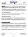
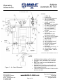
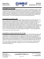
1
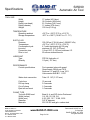
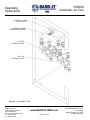
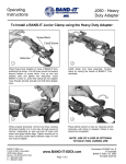
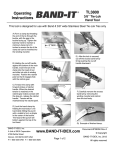
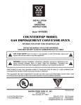
S35099
Automatic Air Tool
Operators
Manual
BAND-IT-IDEX, Inc.
A Unit of IDEX Corporation
4799 Dahlia Street
Denver, CO 80216-0307 USA
P: 1-800-525-0758
F: 1-800-624-3925
WWW.CABLEJOINTS.CO.UK
THORNE & DERRICK UK
www.BAND-IT-IDEX.com
TEL 0044 191 490 1547 FAX 0044 477 5371
TEL 0044 117 977 4647 FAX 0044 977 5582
WWW.THORNEANDDERRICK.CO.UK
Page 1 of 34
Document # S41067 rev. H
© Copyright
BAND-IT-IDEX, Inc. 2010
All rights reserved
S35099
Automatic Air Tool
Table of Contents
Warranty and Safety Information
3
Front Tool Controls
4
Specifications
5
Installation
6-7
Operating Instructions
8-14
Maintenance Instructions
Maintenance Summary
BAND-IT-IDEX, Inc.
A Unit of IDEX Corporation
4799 Dahlia Street
Denver, CO 80216-0307 USA
P: 1-800-525-0758
F: 1-800-624-3925
15-16
17
Troubleshooting
18-21
Repair Parts
22-34
www.BAND-IT-IDEX.com
Page 2 of 34
Document # S41067 rev. H
© Copyright
BAND-IT-IDEX, Inc. 2010
All rights reserved
Warranty and
Safety Information
S35099
Automatic Air Tool
Refer to website for warranty information: http://www.band-it-idex.com/warranty.html
SAFETY RULES:
When applying clamps, care should be taken to make certain that fingers are not in the way of the
clamp being applied. Tensioning the clamp can be stopped immediately by releasing the foot pedal.
Detailed instructions are in this manual and the operator is advised to read it and become familiar
with operating the tool.
IMPORTANT: When clamping a hose end, remember that a tighter clamp keeps the fitting more
secure, but excess tension could damage the hose. Fitting stem must have prominent barbs for
proper retention inside the hose, but must not be sharp to prevent cutting into the hose. Hose, fitting
and clamp must be compatible with each other and the environment used in. If in doubt, consult the
hose or fitting manufacturer or call BAND-IT.
Clamping objects other than hose requires similar precautions.
CAUTION: Improperly tightened clamps may result in dangerous hose assemblies, which could
cause injuries or property damage.
CAUTION: Abuse or use of a hose outside the manufacturers recommended conditions may cause it
to quickly deteriorate and become a safety hazard. This could result in serious injury or property
damage. Inspect and test hose assemblies frequently.
BAND-IT-IDEX, Inc.
A Unit of IDEX Corporation
4799 Dahlia Street
Denver, CO 80216-0307 USA
P: 1-800-525-0758
F: 1-800-624-3925
www.BAND-IT-IDEX.com
Page 3 of 34
Document # S41067 rev. H
© Copyright
BAND-IT-IDEX, Inc. 2010
All rights reserved
S35099
Automatic Air Tool
Front Tool
Controls
CLAMP HOLD
PRESSURE GAUGE
CLAMP HOLD
PRESSURE
ADJUSTMENT
KNOB
CLAMP PULL
PRESSURE GAUGE
CHART SHOWS
RECOMMENDED
HOLD PRESSURE
FOR CLAMPS
CLAMP PULL
PRESSURE
ADJUSTMENT KNOB
AIR SUPPLY
PRESSURE GAUGE
CHART SHOWS MAX.
RECOMMENDED PULL
PRESSURE FOR CLAMPS
FOOT CONTROL
Figure 1 – Front View
BAND-IT-IDEX, Inc.
A Unit of IDEX Corporation
4799 Dahlia Street
Denver, CO 80216-0307 USA
P: 1-800-525-0758
F: 1-800-624-3925
www.BAND-IT-IDEX.com
Page 4 of 34
Document # S41067 rev. H
© Copyright
BAND-IT-IDEX, Inc. 2010
All rights reserved
S35099
Automatic Air Tool
Specifications
TOOL SIZE
Width
Height
Depth (over head)
Depth (chassis)
Weight
17 Inches (431.8mm)
18.5 Inches (469.9 mm)
21.5 Inches (546.1 mm)
11 Inches (279.4 mm)
135 Lbs (61.2 kg)
TEMPERATURE
Operating ambient
Storage temperature
+32°F to +125°F (0°C to +51.5°C)
-20°F to +160°F (-28.8°C to +71.1°C)
SUPPLY AIR
Pressure
Temperature
Consumption/cycle
Line size
Connection size
Filter in tool
100-120 psi (7.0-8.4 kg/cm², 689-827 kPa)
+32°F to +165°F (0°C to +73.8°C)
6.7 cubic feet/minute @ 100 psig
minimum I.D. 3/8" (9.53 mm)
1/4 npt .203" (5.156 mm) minimum I.D.
50 micron sintered bronze
LUBRICANT
Type
Quantity
DTE 24 Hydraulic oil
1/3 pint (.157 liter)
PERFORMANCE
Control specifications
Foot operated valve with guard
Guard meets OSHA part 1910.
Sections 217 and 218, June 1974
Valve meets ANSI B11.1-1971
Water drain connection
Tube I.D. 1/8" (3.175 mm)
Cycle time
Pull-up clamp
Cut-off clamp
Eject tail and reset
10 seconds
3.5 seconds
1.5 seconds
1.0 seconds
CLAMP TYPE
Tool with S260 head
Width (inches)
Width (mm)
Diameter
Materials
BAND-IT-IDEX, Inc.
A Unit of IDEX Corporation
4799 Dahlia Street
Denver, CO 80216-0307 USA
P: 1-800-525-0758
F: 1-800-624-3925
Band-It Jr. and SID Junior Preformed
1/4, 3/8, 1/2, 5/8, 3/4
6.35, 9.53, 12.7, 15.88, 19.05
3/4"-8" diameter
201/316 SS and galv. carbon steel
www.BAND-IT-IDEX.com
Page 5 of 34
Document # S41067 rev. H
© Copyright
BAND-IT-IDEX, Inc. 2010
All rights reserved
S35099
Automatic Air Tool
Installation
UNPACKING:
1. Lift the outer tube of the packing box. Carefully examine the tool for shipping damage as
evidenced by dents, loose parts, etc. Report any shipping damage found to the carrier that
delivered the tool.
2. Lift out foot control valve and remove protective packing.
3. Remove the side panels (2) of the tool chassis. Keep the screws for reassembly. The tool is
bolted to the bottom base of the shipping carton. Remove these screws.
4. Lift the tool using the hand hole at the rear top of the chassis and the handle on the tool head.
Support the foot control valve and its lines to avoid damage while moving the tool.
5. The shipping carton has been specially prepared to protect the tool. It is recommended to keep
the carton and hardware so the tool can be repacked in it, should it be desirable to ship the tool to
another location or return it to the factory for service.
6. CAUTION: The tool weighs approximately 117 pounds. The aid of a suitable lifting device is
recommended for handling the tool. Use the lift points provided. See figure 2.
MOUNTING:
1. Locate the tool in its desired location, and secure the tool to the mounting surface with 5/16"
diameter bolts (4). Place the foot control valve on the floor. See figure 2 for location of the bolts.
2. A drain tube connected to the pipe connection on the bottom of the filter is supplied so the water,
automatically ejected, can be dumped. This drain line can be connected to a permanent drain
(recommended) or it can drain into a container. This line can be routed through the opening in the
front of the chassis. If alternate routing of the hose is desired, an access hole must be cut through
the chassis at the desired location.
3. Prepare the incoming air line, the supply air should be clean (filtered) and free of moisture.
Recommended air source hook up should be done with a quick-disconnect coupling such as a
Hansen 3000 series 1/4 npt socket and plug, or equivalent. For permanent hook up, use of a
shut-off valve in the air line is recommended to enable shut-off of the incoming air when servicing
the tool. Route the air line through the access hole in the rear of the chassis. Alternate routing of
the supply air can be done through the bottom of the chassis. Connect the air line to the tee fitting
in the inlet port of the filter. See figure 2.
4. Remove the filler plug of the lubricator, see figure 4, and fill the bowl to the fill line with the DTE 24
hydraulic oil supplied with the tool. Note: The lubricator cannot be filled while tool is pressurized.
5. Do not fill past the fill line on the bowl. Reattach filler plug. The tool is ready for preliminary
operation. Do not reassemble the side panels. The lubricator must be checked for proper
operation. Refer to the operating instructions section.
WARNING: This tool is intended for use with industrial compressed air systems. The tool must not
be used where pressure or temperature may exceed the maximum rated operating condition as
stated in the specifications section. The polycarbonate plastic bowls used in this tool could be
damaged and possibly burst if exposed to strong alkali’s, compressor oils containing aromatic
hydrocarbons, synthetic oils, or fumes of these substances in contact with the polycarbonate plastic
bowls, externally or internally.
BAND-IT-IDEX, Inc.
A Unit of IDEX Corporation
4799 Dahlia Street
Denver, CO 80216-0307 USA
P: 1-800-525-0758
F: 1-800-624-3925
www.BAND-IT-IDEX.com
Page 6 of 34
Document # S41067 rev. H
© Copyright
BAND-IT-IDEX, Inc. 2010
All rights reserved
S35099
Automatic Air Tool
Installation
LIFT HERE
17.077
20.498
18.380
12.850
10.880
18.500
9.50
POSITION OF ITEM
FOR INSERTION OF
CLAMP INTO TOOL
1.375
8.9
2.090
8.50 X 14.50
PARALLEL HOLE
PATTERN
.41 DIA X 4 PLACES
15°
Figure 2 – Tool Overall Size
BAND-IT-IDEX, Inc.
A Unit of IDEX Corporation
4799 Dahlia Street
Denver, CO 80216-0307 USA
P: 1-800-525-0758
F: 1-800-624-3925
www.BAND-IT-IDEX.com
Page 7 of 34
Document # S41067 rev. H
© Copyright
BAND-IT-IDEX, Inc. 2010
All rights reserved
S35099
Automatic Air Tool
Operating
Instructions
PRELIMINARY
Read air supply pressure gauge (Fig. 1). Air pressure should not be lower than 100 psi and no higher
than 120 psi. Depress the foot control valve pedal and hold the pedal down so the tool operates
through its cycle. When the tool has completed the cycle, release the pedal and the tool will reset for
the next cycle.
Cycle the tool three or four times without attempting to apply a clamp and observe the tool as it cycles
to become familiar with the operating sounds and action of the tool. During these cycles, check the air
lines for leaks and observe that the piston rods of the pull cylinder and cut-off cylinder operate freely.
CLAMP PULL PRESSURE GAUGE
Read the pressure shown on the clamp pull pressure gauge (Fig. 1) as the tool goes through the pullup cycle. The pressure to be read is the pressure shown at the time the control valve shifts.
Pressures shown on the gauge after the valve has shifted should be ignored.
CLAMP HOLD PRESSURE GAUGE
Read the pressure shown on the clamp hold pressure gauge (Fig. 1) as the tool goes through that
portion of the cycle. The pressures observed are those to which the tool is set to operate. The
pressure to be read is the pressure shown at the time the cut-off cylinder operates the cam to lock the
clamp and to cut-off clamp tail. Pressures shown on gauge at other times during the cycle are
unimportant and should be ignored. The cycle time, clamp pull pressure and clamp hold pressure
should always be checked as described prior to attempting to apply a clamp on an item.
ADJUSTMENT OF LUBRICATOR
The lubricator adjustment must be checked to determine that the drip rate is one drip per cycle (set
and locked at Band-It, does not need to be adjusted). Locate the drop rate adjustment knob on the
top of the lubricator (Fig. 4). The drip rate adjustment should be made only when there is a constant
flow of air through the lubricator (operate the tool).
Locate the sight dome just below the adjustment knob and observing the oil as it drips downward into
the lubricator. To adjust the drip rate, turn the slotted red rotator in sight feed dome counter-clockwise
to increase drip rate: clockwise to decrease the drip rate. When the proper rate of one drop per cycle
is obtained, stop adjustment. Do not operate the tool at a higher drip rate than recommended as the
larger amount of lubricant could adversely affect the operation of the time-delay valves and also result
in accumulation of lubricant near the air exhaust.
Operation at a lower drip rate can starve the cylinders and valves and reduce their life due to
premature wear.
BAND-IT-IDEX, Inc.
A Unit of IDEX Corporation
4799 Dahlia Street
Denver, CO 80216-0307 USA
P: 1-800-525-0758
F: 1-800-624-3925
www.BAND-IT-IDEX.com
Page 8 of 34
Document # S41067 rev. H
© Copyright
BAND-IT-IDEX, Inc. 2010
All rights reserved
S35099
Automatic Air Tool
Operating
Instructions
100-120 PSI AIR SUPPLY
LEGEND:
1
2
3
4
5
6
7
8
9
10
11
12
13
14
15
16
17
18
FRONT
PANEL
CLAMP
HOLD
CONTROL
CLAMP PULL
CONTROL
19
20
21
FILTER, AIR
LUBRICATOR
VALVE, FOOT OPERATED
VALVE, CLAMP PULL
PRESSURE CONTROL
GAUGE, CLAMP PULL
PRESSURE
VALVE, PULL-UP CYLINDER
CYLINDER, CLAMP PULL
VALVE, TIME DELAYED,
PULL-UP CYLINDER
VALVE, TIME DELAYED,
CUT-OFF
GAUGE, CLAMP HOLD
PRESSURE
VALVE, CLMAP HOLD
PRESSURE CONTROL
VALVE, CUT-OFF CYLINDER
CYLINDER, CLAMP LOCK
AND CUT-OFF
HEAD, CLAMP
VALVE, QUICK EXHAUST
VALVE, CHECK
MUFFLER, AIR EXHAUST
GAUGE, AIR SUPPLY
PRESSURE
MUFFLER, AIR EXHAUST 1/4
TEE, STREET 1/4-18 NPT
CROSS, BRASS, 1/4 NPTF,
FEMALE
▲ ON TOOLS SERIAL NUMBER 168 AND UP
NOTES:
1
2
3
4
Figure 3 – Air Control Schematic
5
SYSTEM SHOWN IN NORMAL (OFF) POSITION.
TO START CYCLE, DEPRESS FOOT CONTROL
VALVE 3.
KEEP FOOT CONTOL VALVE DEPRESSED TO
COMPLETE CYCLE.
RELEASE FOOT CONTROL VALVE WHEN THE
COMPLETE CYCLE IS DONE OR TO STOP THE
TOOL DURING ITS CYCLE.
□ REFERS TO IDENTIFICATION LETTERS PLACED
ON EACH AIR LINE.
BAND-IT-IDEX, Inc.
A Unit of IDEX Corporation
4799 Dahlia Street
Denver, CO 80216-0307 USA
P: 1-800-525-0758
F: 1-800-624-3925
www.BAND-IT-IDEX.com
Page 9 of 34
Document # S41067 rev. H
© Copyright
BAND-IT-IDEX, Inc. 2010
All rights reserved
Operating
Instructions
S35099
Automatic Air Tool
ADJUSTMENT OF CYCLE TIME
The cycle time consists of two adjustable time elements. These can be adjusted as desired to: match
the operator’s skill, compensate for the difficulty of the assembly of the item being clamped, increase
or decrease the speed of the tool to allow the tool to tension the clamp, etc. A six second time for a
complete tool cycle is recommended as a reasonable time to make clamp assemblies, avoid operator
fatigue, and obtain a good production rate. The total time to apply a clamp will be increased by the
time to load the clamp on the item being clamped into the tool and removing the item and the spent
tail after clamping. It is not likely that the cycle time will need be adjusted frequently.
ADJUSTMENT OF CLAMP PULL TIME
This is the time needed to allow the pull cylinder to tighten the clamp and to build air pressure to the
pressure level selected. Pulling clamps with less than 40 psi does not require as much time to
tension the clamp so, if desired, the tool cycle time can be shortened. Conversely, if the tool is used
for clamps requiring pull pressure of 40 psi, or greater, the cycle time will need to be longer. To
adjust this time, remove the right side panel (4 screws) and locate the time delay valve (Fig. 4).
Locate the knurled adjustment knob (secured with a lock nut). Loosen the lock nut with a wrench and
turn the screw clockwise (right hand) to increase the cycle time, turn the screw counter-clockwise (left
hand) to decrease the cycle time. After an adjustment, it is recommended to cycle the tool a few
times to check the time to which the tool has been reset. When satisfied with the time, tighten the
lock nut to secure the adjustment knob and reassemble the side panel. A reasonable elapsed time
for this portion of the cycle is three seconds.
ADJUSTMENT OF CLAMP LOCKING AND CUT-OFF TIME
This is the time required to reduce the pressure in the pull cylinder to the clamp holding pressure and
to actuate the cut-off cylinder which locks the clamp and cuts off the clamp tail. For tools equipped
with the Band-It Jr. preformed clamp head, the operator must have time to roll the clamp up to
position for cut-off. Time required for roll up is dependent upon operator skill, familiarity with the tool,
weight and size of the item being clamped. To adjust this cycle time, remove the left side panel (four
screws) and locate the time control valve (Fig. 5). Locate the knurled adjustment knob (secured with
a lock nut). Loosen the lock nut with a wrench and turn the screw clockwise to increase the cycle
time, counter-clockwise to decrease the cycle time. Cycle the tool a few times to make certain the
cycle time is changed to that desired. Tighten the lock nut to secure the adjustment knob and
reassemble the side panel.
BAND-IT-IDEX, Inc.
A Unit of IDEX Corporation
4799 Dahlia Street
Denver, CO 80216-0307 USA
P: 1-800-525-0758
F: 1-800-624-3925
www.BAND-IT-IDEX.com
Page 10 of 34
Document # S41067 rev. H
© Copyright
BAND-IT-IDEX, Inc. 2010
All rights reserved
S35099
Automatic Air Tool
Operating
Instructions
CLAMP PULL TIME
DELAY VALVE
CLAMP PULL TIME
ADJUSTMENT SCREW
LUBRICATOR FILLER
PLUG
LUBRICATOR DRIP RATE
ADJUSTMENT KNOB
FILTER
Figure 4 – Right Side of Tool
BAND-IT-IDEX, Inc.
A Unit of IDEX Corporation
4799 Dahlia Street
Denver, CO 80216-0307 USA
P: 1-800-525-0758
F: 1-800-624-3925
www.BAND-IT-IDEX.com
Page 11 of 34
Document # S41067 rev. H
© Copyright
BAND-IT-IDEX, Inc. 2010
All rights reserved
S35099
Automatic Air Tool
Operating
Instructions
CLAMP HOLD TIME
DELAY VALVE
CLAMP HOLD TIME
ADJUSTMENT SCREW
CUT-OFF
CONTROL VALVE
PULL-UP
CONTROL VALVE
Figure 5 – Left Side of Tool
BAND-IT-IDEX, Inc.
A Unit of IDEX Corporation
4799 Dahlia Street
Denver, CO 80216-0307 USA
P: 1-800-525-0758
F: 1-800-624-3925
www.BAND-IT-IDEX.com
Page 12 of 34
Document # S41067 rev. H
© Copyright
BAND-IT-IDEX, Inc. 2010
All rights reserved
S35099
Automatic Air Tool
Operating
Instructions
ADJUSTMENT OF CLAMP PULL PRESSURE
This adjustment will be required for different materials and construction of the items being clamped.
A convenient chart summarizing the maximum pressures to use for the most commonly used Band-It
clamps is located on the lower right front panel (Fig. 1). Note that this chart shows the maximum
pressure to be used. Pulling clamps to pressures higher than recommended may result in clamp
breakage or improper clamp locking caused by excessive stretching of the clamp band. It is likely
that a pressure setting slightly below this maximum will be satisfactory.
Some testing, by assembling clamps on a test specimen of the item being clamped, may be useful to
determine the desirable pressure setting. To adjust the pressure, locate the clamp pull pressure knob
(Fig. 1) on the front panel. Adjustment is made by a knurled knob secured with a lock ring. Pull the
lock ring out toward the knob so it can be turned. Turn the knob clockwise to increase the pressure
setting; counter-clockwise to decrease the pressure setting. The pressure to which the tool is set is
shown on the gauge beside the knob (Fig. 1). To check the pressure to which the tool is set, cycle
the tool and observe the maximum pressure reading shown on the gauge when the piston is all the
way in. Note that this pressure must be read during the pull cycle only. When the desired pressure is
obtained, push the lock ring in and the knob is locked. Note: It is important to adjust so the pressure
observed on the gauge is regulated to the desired pressure by the time the tool cycles and not
attempt to set the pressure so that it is changing rapidly and merely "passing through" the desired
pressure at the time the tool operates.
The latter condition can result in wide variations of pull pressure as the air pressure fluctuates.
ADJUSTMENT OF CLAMP HOLD PRESSURE
The pressure in the clamp pull cylinder must be reduced to allow the tool to lock the clamp after
pulling and to satisfactorily cut off the clamp tail. This pressure is adjusted by the knurled knob on the
left front panel (Fig. 1). The pressure to which the tool is set is shown on the gauge beside the knob
(Fig. 1). Note that during this cycle, the pressure drops rapidly. The tool must be set so the desired
pressure is shown at the instant the cut-off cylinder moves the cam out to lock the clamp and cut off
the tail. To adjust this pressure, pull the lock ring out and turn the knob clockwise to increase the
pressure; counter-clockwise to decrease the pressure.
A convenient chart summarizing the recommended pressures to use for the most common sizes of
Band-It clamps is located on the lower left front panel. Note that this chart shows only recommended
pressure settings; operation outside these pressure settings will possibly result in poor locks on the
clamps, breaking of the clamp band (pressure too high), or difficulty in cutting off the tail (pressure too
low). The tool should be cycled to check the pressure setting of the tool. When satisfactory, push the
lock ring in to secure the adjustment knob. Note: It is important that the pressure be adjusted so the
pressure is regulated to the desired holding pressure at the time the cut-off cylinder actuates and not
attempt to adjust the tool so the pressure is changing rapidly at the time the cylinder actuates. This
will result in consistent holding pressures.
The tool is ready for Band-It Jr. clamps.
BAND-IT-IDEX, Inc.
A Unit of IDEX Corporation
4799 Dahlia Street
Denver, CO 80216-0307 USA
P: 1-800-525-0758
F: 1-800-624-3925
www.BAND-IT-IDEX.com
Page 13 of 34
Document # S41067 rev. H
© Copyright
BAND-IT-IDEX, Inc. 2010
All rights reserved
S35099
Automatic Air Tool
Operating
Instructions
APPLYING CLAMPS
The following step-by-step instructions should be followed to successfully tension and lock a clamp.
This information is also summarized on a decal located on the lower left front panel and explained in
further detail in other sections of this manual.
CAUTION! When operating, do not place fingers near or between the clamp band and the item being
clamped as they could be pinched.
1. Set and/or check clamp pull pressure.
2. Slide clamp over object being clamped. Insert tail of clamp into the open slot of the backing
plate of the clamp tool head. Push the clamp tail into the head as far as possible (the clamp
buckle should be almost touching the backing plate of the clamp tool head).
3. Support the item being clamped. The operator should hold the object so the clamp buckle is
essentially level with the tail and should also keep the object horizontal and lift it if necessary
as the weight of the assembly is not held by the clamp.
4. Depress the pedal of the foot control valve and hold the pedal down as the tool operates
through its cycle.
5. Allow the tool to tighten the clamp and observe the pull pressure. The tool will then
automatically cycle and lower the pressure in the pull cylinder to the hold pressure.
6. Roll up hose when clamp hold gauge drops to approximate roll up pressure shown in chart
below. Rotate object being clamped upward and position clamp buckle under shear hook of
machine.
7. Support the object being clamped as the cut-off cylinder automatically pushes the cam outward
to perform and cut-off operation.
Clamp Width
(mm)
Pull-Up Pressure
(psi)
Stainless Steel
Carbon
Steel
201 SS
316 SS
1/4" (6.35)
3/8" (9.525)
1/2" (12.7)
5/8" (15.875)
3/4" (19.05)
15
25
40
50
60
15
20
35
40
50
Hold Pressure
(psi)
Roll Up Pressure
(psi)
6-7
6-7
8-9
9-10
10-12
9-10
9-10
11-12
12-14
13-16
25
40
50
60
STOPPING THE TOOL
Should the occasion arise that the tool operation must be stopped to clear a jammed clamp, the tool
cycle can be stopped by releasing the foot control valve and the tool will reset itself. Should the
control valve again be depressed prior to allowing the tool to reset, erratic cycling will result.
BAND-IT-IDEX, Inc.
A Unit of IDEX Corporation
4799 Dahlia Street
Denver, CO 80216-0307 USA
P: 1-800-525-0758
F: 1-800-624-3925
www.BAND-IT-IDEX.com
Page 14 of 34
Document # S41067 rev. H
© Copyright
BAND-IT-IDEX, Inc. 2010
All rights reserved
S35099
Automatic Air Tool
Maintenance
Instructions
VALVES AND GAUGES
No periodic maintenance is required.
AIR LINES
No periodic maintenance is required. However, checking the tube connectors to see that they are
tight when the tool is serviced is recommended.
FILTER
Clean the filter a minimum of every six months or more frequently if dirt particles are observed to be
accumulating in the bowl.
LUBRICATOR
Drain and clean once a year or clean immediately if the lubricator is observed to be discolored or
contaminated. Keep the oil level to the fill line. DO NOT over-fill since this reduces the efficiency of
the lubricator. Discard the oil drained, do not reuse.
Warning: The lubricator should be refilled with DTE 24 hydraulic oil only. The
use of other oils may cause damage to the system.
CLAMP TAIL GRIPPER PLATE
Remove the clamp tail gripper as shown in figure 6, and remove the right hand side panel. Depress
the pedal of the fool control valve and allow the tool to cycle as though it was pulling a clamp. When
the piston rod is pulled all the way back, disconnect or shut off the air supply. The tool will stop its
action and the plate can be reached at the end of the piston rod. Slide tripper plate out of the piston
rod. Clean to remove any accumulation of dirt, debris, etc. and apply molybdenum disulfide lubricant
such as Molykote type G-n or equivalent to the edges of the plate. Reassemble the plate with
chamfered edge up and toward the front of the tool. Slide the plate all the way into the piston rod.
Reconnect or turn on the air. The tool will complete the cycle and return the piston rod toward the
front of the tool. Reassemble the clamp tail gripper and the tool is ready to use.
CLAMP TAIL GRIPPER
ACCESS HOLE ON
EITHER SIDE OF BASE
GRIPPER PIVOT PIN
SET SCREW
Figure 6 – Clamp Tail Gripper
BAND-IT-IDEX, Inc.
A Unit of IDEX Corporation
4799 Dahlia Street
Denver, CO 80216-0307 USA
P: 1-800-525-0758
F: 1-800-624-3925
www.BAND-IT-IDEX.com
Page 15 of 34
Document # S41067 rev. H
© Copyright
BAND-IT-IDEX, Inc. 2010
All rights reserved
S35099
Automatic Air Tool
Maintenance
Instructions
GENERAL
This tool has been designed and constructed to reduce minimum maintenance. Periodic checking of
the tool to check for loose screws and fittings that may have loosened is necessary. A thorough
check for air leaks, wear on the moving parts, etc. is recommended to keep the tool in peak operating
condition.
AIR EXHAUST MUFFLERS
Remove and clean once a year minimum with a degreaser (such as Gunk) to remove accumulated oil
deposits.
CYLINDERS
These cylinders have seals to keep dirt from entering the cylinders but the dirt accumulated at the
seals should be cleaned away a minimum of once a year (more often if used in a very dirty area).
CLAMP TAIL GRIPPER
To remove gripper, loosen set screw in bottom of piston rod head (Figure 6) and tap gripper pivot pin
through access holes in base and remove pin, slide gripper lever off spring loop.
Remove accumulated dirt and debris from the recesses or the teeth with a pointed object or knife
blade. This should be done frequently when pulling plated carbon clamps. Apply Molykote type G-n
or equivalent lubricant to the pivot pin.
JR. CLAMP HEAD
Keep sliding surfaces or the cam and shear hook well lubricated with a thin film of molybdenum
disulfide lubricant such as Molykote G-n lubricant or equivalent.
CUTTER BLADE/BACKING PLATE
Check daily to be certain these are tight. Frequently check both for chipped or broken edges and
replace if these are found. Inspect the lower edge of the cutter blade for sharp edges. If a sharp
edge is found, use a fine grained sharpening or honing stone and lightly stone the lower edges to a
smooth radius (Figure 7).
USE A FINE STONE AND WHET
A RADIUS ON THIS EDGE SO IT
DOES NOT SCRAPE
FINGERNAIL
Figure 7 – Cutter Blade Edge
BAND-IT-IDEX, Inc.
A Unit of IDEX Corporation
4799 Dahlia Street
Denver, CO 80216-0307 USA
P: 1-800-525-0758
F: 1-800-624-3925
www.BAND-IT-IDEX.com
Page 16 of 34
Document # S41067 rev. H
© Copyright
BAND-IT-IDEX, Inc. 2010
All rights reserved
S35099
Automatic Air Tool
Maintenance
Summary
COMPONENT
Cutter Blade and
Backing Plate
FREQUENCY
Daily
CHECK
Check to see if blade is loose.
Look for broken or chipped
edge. Feel lower edge for
sharp edge.
ACTION
Tighten screws and replace
if necessary. With stone,
hone edge of cutter blade
round (figure 7).
Check for build up of foreign
material in teeth.
Remove and clean with
pointed object or knife blade.
Clamp Tail Gripper
2,000 clamps
pulled
Cam Contact
Surface
2,000 clamps
pulled
Observe surface for lubricant.
Lubricate with molybdenum
disulfide grease such as
Molykote G-n.
6 months
Check for accumulation of dirt.
Clean with soap and warm
water.
2,000 clamps
pulled
Check lubricant level. Observe
for contaminated or discolored
lubricant.
Refill to fill level with DTE 24
hydraulic oil. If needed, drain
and clean lubricator with
soap and warm water before
refilling.
Look for build up of dirt.
Remove and clean with nonflammable degreaser such
as Gunk.
Check for accumulation of dirt
on piston rod cylinders.
Clean with soap and warm
water.
Filter
Lubricator
Air Exhaust Mufflers
(5)
Cylinders (2)
6 months
Yearly
Cam Roller
6 months
Clean surface of roller and
wipe away excess lubricant.
Lubricate with SAE 30 oil.
Clamp Head
6 months
Check for loose mounting
screws.
Tighten mounting screws.
Trip Plate
6 months
Clean to remove dirt, debris,
etc.
Apply Molykote G-n or
equivalent.
BAND-IT-IDEX, Inc.
A Unit of IDEX Corporation
4799 Dahlia Street
Denver, CO 80216-0307 USA
P: 1-800-525-0758
F: 1-800-624-3925
www.BAND-IT-IDEX.com
Page 17 of 34
Document # S41067 rev. H
© Copyright
BAND-IT-IDEX, Inc. 2010
All rights reserved
S35099
Automatic Air Tool
Troubleshooting
GENERAL
This section contains information on problems that may possibly occur and the corrections to be
made to restore the tool to proper operating condition. When using this clamp application tool,
problems can occur with the tool or with the clamp being assembled. The guidelines shown and
attention by the tool operator will result in identifying the problem so a timely correction can be made.
PROBLEM
1) Clamp tail breaks
during pull up.
OBSERVATION
- Knife-like edge on tail, edge of band
on clamp is scarred and heavily
scraped, deposits of metal on
underside of tail at buckle edge.
- Tail is broken at 45° angle and/or
section thinned at break.
- Tail breaks during pull-up.
2) Clamp pulls
satisfactorily but
does not lock
properly.
- Band-It Jr. lock is formed but pulls
through buckle.
3) Foot control
leakage.
- Air exhausts through exhaust port
when tool is not being operated.
4) Tool operation is
erratic, especially
when tool is
resetting.
- Pull cylinder is jerky during return.
- Tool makes stuttering noises as air
exhausts from the cylinder(s).
BAND-IT-IDEX, Inc.
A Unit of IDEX Corporation
4799 Dahlia Street
Denver, CO 80216-0307 USA
P: 1-800-525-0758
F: 1-800-624-3925
CORRECTION
- Cutter blade broken, replace.
Cutter blade has sharp edge, remove sharp
edge.
- Pull up pressure set too high, reduce
pressure.
- Check hold pressure and reduce to
recommended level. Roll up is being
attempted before pressure has dropped
below recommended PSI. Operator should
wait for pressure to drop or decrease the
holding cycle time (see operating
instructions).
- Check hold pressure and reduce for
maximum level recommended for clamp
width and material
- Clamp may have been rolled up at a higher
pressure than recommended. Operator
should wait for pressure to drop or decrease
the holding cycle time (see operating
instructions).
- Disconnect tubes L and B at cylinder end.
Check each port for any air exhaust or faulty
cylinder seals and repair.
- Check for debris under foot control valve
pedal, or check to see that the valve is
operated fully when pedal is depressed.
www.BAND-IT-IDEX.com
Page 18 of 34
Document # S41067 rev. H
© Copyright
BAND-IT-IDEX, Inc. 2010
All rights reserved
S35099
Automatic Air Tool
Troubleshooting
PROBLEM
5) Clamp pulls jerky.
Clamp may or
may not lock.
6) Clamp tail slipping
in clamp tail
gripper.
OBSERVATION
CORRECTION
- Motion during pull up is erratic and
sticky, but the edges of the band on
the clamp are not scarred.
- Check clamp pull pressure and increase
pressure if pull is below maximum
recommended pressure.
-The object being clamped may be
held in a twist while the clamp is
being tightened.
- Straighten/support the object and keep as
level as possible. Lift the object or support it
so the buckle is straight with the clamp tail.
-The object being clamped is heavy or
has downward pressure on it.
- Check to see if the band gripper pin has
loosened and is dragging on the sides of the
base. Relocate and tighten set screw if it is
loose (fig. 6).
- Clamp pulls and locks satisfactorily
but tail is sliding or scraping in clamp
tail gripper.
7) Clamp tail cannot
be inserted into
tool.
- Cycle tool and observe that the
gripper lever tail moves as the piston
rod returns to contact the clamp
head.
8) Clamp tail is
crumpled or
trapped as the
tool resets.
- Tail is caught in the tool instead of
being ejected back through or below
the clamp head.
BAND-IT-IDEX, Inc.
A Unit of IDEX Corporation
4799 Dahlia Street
Denver, CO 80216-0307 USA
P: 1-800-525-0758
F: 1-800-624-3925
- Pull up cylinder may need lubrication.
Check the lubricator for oil and to see if the
lubricator is working properly. Add oil and
correct the setting and cycle the tool a
number of times to lubricate the cylinder
prior to resuming operation.
- Remove the clamp tail gripper and clean the
teeth. Observe for flattened teeth. If found,
gripper should be replaced. Note that
chipped teeth may hold band satisfactorily
and use is not detrimental, but a
replacement gripper should be ordered.
- Tripper plate may be stuck due to dirt or lack
of lubricant. Clean and relubricate the plate.
- Gripper level not opening. Tripper plate may
be broken or binding. Disassemble gripper
lever and/or tripper plate and clean or
replace defective item (fig. 6).
- Operate the tool and KEEP THE FOOT
CONTROL VALVE PEDAL DEPRESSED.
Reach under piston rod and locate the band
gripper lever. Rotate the lever toward the
clamp head and allow the tail to fall out of
the tool. If the tail does not fall out, use
pliers to grasp the clamp tail and remove it.
Release foot control valve pedal. NEVER
position your fingers anywhere but on the
gripper lever and keep the foot control valve
depressed.
www.BAND-IT-IDEX.com
Page 19 of 34
Document # S41067 rev. H
© Copyright
BAND-IT-IDEX, Inc. 2010
All rights reserved
S35099
Automatic Air Tool
Troubleshooting
PROBLEM
9) Tool doesn’t cut
off clamp.
OBSERVATION
- Cut-off cylinder stalls and does not
cut off clamp tail.
- Clamp tail bends and allows tool to
force buckle past cutter blade edge.
10) Tool never
reaches the
selected pull
pressure. Tool
operation may
be erratic in this
portion of the
cycle.
11) Tool takes
excessive time
for clamp pullup.
12) Tool does not
tighten clamps
- Pressure observed increases, then
drops rapidly and jumps back up to a
higher pressure.
- Tool cycles to start the clamp holding
cycle before selected pressure is
observed on gauge.
- Tool pulls the clamp and reaches the
selected holding pressure, then the
operator waits before the tool
operates to the holding and cut-off
cycle.
- Selection of higher clamp pull
pressure does not result in tighter
clamps. Excessive amount of air is
exhausting from the quick-exhaust
valve.
CORRECTION
- Check for loose or broken cutter blade.
Tighten screws if loose. Replace cutter
blade if broken.
- Reset clamp hold pressure to recommended
pressure.
- If air line supply pressure is below 100 PSI,
stop operation and correct or allow pressure
to rise above 100 PSI.
- Check cut-off cylinder air cushion valve (fig.
14). It might be screwed in too deep.
- Cut-off cylinder piston seals leak. Loosen
nut off of tube Q. If air is still escaping
remove cylinder and replace seals.
- Cut-off cylinder piston rod may be binding.
Shut off air supply and remove tubes B and
Q and operate piston rod by hand to see if it
moves freely. If not, check back-up roller for
.010” clearance or remove cylinder.
- Lubricate between shear hook and cut-off
cam.
- Increase the clamp pull cycle time to allow
the tool to regulate to the selected pressure.
- Air line pressure may be lower than the
selected pressure. Check and correct.
- Check the system for an air leak.
- Decrease the clamp pull cycle time (fig. 4).
- Check for air system leak. Tighten or
replace defective items.
- Pull cylinder seal may be leaking. Operate
tool to stall the cylinder. Remove tube N and
if air is escaping, disassemble pull cylinder
and repair.
- Check to see if gripper level pin is dragging
on the base. Reposition and retighten the
set screw that retains the pin (fig 6).
BAND-IT-IDEX, Inc.
A Unit of IDEX Corporation
4799 Dahlia Street
Denver, CO 80216-0307 USA
P: 1-800-525-0758
F: 1-800-624-3925
www.BAND-IT-IDEX.com
Page 20 of 34
Document # S41067 rev. H
© Copyright
BAND-IT-IDEX, Inc. 2010
All rights reserved
S35099
Automatic Air Tool
Troubleshooting
PROBLEM
13) Tool takes
excessive time
prior to actuation
of cut-off cylinder.
OBSERVATION
- Tool reaches clamp hold pressure
selected and operator must wait a
second or more before cut-off cylinder
actuates.
CORRECTION
- Decrease the actuation time for the cut-off
cylinder (fig. 5).
- Time delay valve may be clogged. Remove
needle valve and observe. If dirty, remove valve,
disassemble and clean.
- Cut-off valve may be sticking. Remove cut-off
valve, disassemble and clean or replace (fig. 5).
14) Tool does not
read clamp hold
pressure
selected.
- Cut-off cylinder actuates before the clamp
hold pressure selected shows on the
gauge.
- Increase the actuation time for the cut-off
cylinder.
- Increase the clamp hold pressure.
- Pressure drops below desired pressure
and regulates at a lower pressure.
- Adjust valve. If no response, replace hold
pressure valve.
- Pressure never regulates.
BAND-IT-IDEX, Inc.
A Unit of IDEX Corporation
4799 Dahlia Street
Denver, CO 80216-0307 USA
P: 1-800-525-0758
F: 1-800-624-3925
www.BAND-IT-IDEX.com
Page 21 of 34
Document # S41067 rev. H
© Copyright
BAND-IT-IDEX, Inc. 2010
All rights reserved
S35099
Automatic Air Tool
Repair Parts
GENERAL
This tool is designed and manufactured to require minimal maintenance and to have a long life.
However, certain parts may require periodic replacement due to normal wear. Replacement of these
items will enable keeping the tool operating to its peak efficiency. The part lists shows all parts that
may be required to repair the tool.
HOW TO ORDER REPAIR PARTS
This parts list is grouped into major sub-assembly sections of the tool. Components that also can be
repaired are shown in their respective sections. Locate the part needed on the drawings and observe
the number attached to it, match this number with "ITEM" on repair parts list. Order the parts using
the six-digit part number and complete description shown on the repair parts list. Should a serial
number be required, find the serial number of the tool on the nameplate located on the exterior of the
front panel in the lower left-hand corner (Fig. 8). It is recommended that the serial number
information be supplied on all repair part orders. Submit the order to your BAND-IT distributor or
representative for processing. Note that some parts have part numbers marked on the parts, this
information may be helpful in assuring that the correct part is ordered, but always consult the repair
parts list and supply all the information as suggested in this section. It is recommended that items
such as nuts, bolts, etc, be purchased locally.
Figure 8 – Tool Serial Number Location
BAND-IT-IDEX, Inc.
A Unit of IDEX Corporation
4799 Dahlia Street
Denver, CO 80216-0307 USA
P: 1-800-525-0758
F: 1-800-624-3925
www.BAND-IT-IDEX.com
Page 22 of 34
Document # S41067 rev. H
© Copyright
BAND-IT-IDEX, Inc. 2010
All rights reserved
S35099
Automatic Air Tool
Repair Parts
ITEM
1
2
3
4
5
6
7
8
9
10
11
12
13
14
15
16
17
18
19
20
21
22
23
24
25
26
27
28
29
30
31
32
33
34
35
36
37
PART NO.
S44479
S37889
S34787
S37987
S38087
S38277
S38377
S38477
S31788
S38587
S38687
S38787
H66088
S32687
S33787
J90987
S25087
S32887
S33987
R00622
S26387
J66587
A93087
S32787
G92188
S26587
S27587
QTY.
1
1
1
1
1
1
1
1
1
1
1
1
2
4
4
8
3
27
8
1
11
8
4
10
4
4
2
S39079
S36387
S39087
P06486
J65387
S26079
S31589
S41185
S42487
1
8
1
2
8
1
1
4
1
BAND-IT-IDEX, Inc.
A Unit of IDEX Corporation
4799 Dahlia Street
Denver, CO 80216-0307 USA
P: 1-800-525-0758
F: 1-800-624-3925
DESCRIPTION
HEAD ASSEMBLY, (FIG. 1)
CONTROL AIR ASSEMBLY, (FIG. 10)
CHASSIS, WELDED
BRACKET, BASE MOUNTING
BRACKET, L-TOP
DECAL, CLAMP HOLD AND PULL CONTROL
DECAL, CLAMP HOLD
DECAL, CLAMP PULL
DECAL, NAMEPLATE AND SERIAL NO.
CLIP, SINGLE HOSE
CLIP, SINGLE VALVE
CLIP, DOUBLE HOSE
SCREW, HEX HD, 1/4-20 X 1.00
SCREW, SOC HD, 1/4-20 X 1.75
SCREW, SOC HD, 1/4-20 X 2.50
SCREW, SOC HD, 5/16-18 X 0.88
SCREW, SOC HD, NYLON PATCH, 1/4-20 X 0.63
WASHER, FLAT, 0.22 ID X 0.63 OD X 0.06
WASHER, FLAT, 0.34 ID X 0.69 OD X 0.06
PAD, RUBBER, 2 X 5 X 0.75
WASHER, LOCK, 0.25
WASHER, LOCK, 0.31
SCREW, FLAT HD, SOC #10-32 X 0.75
NUT, HEX, 1/4-20
NUT, HEX, 5/16-18
LOCKNUT, NYLON INSERT #10-32 UNF
SCREW, SHEET METAL, #8
PANEL, SIDE, SLOTTED
U-TAP CLIP, #10-24
PANEL, SIDE, PLAIN
DECAL, BAND-IT LOGO
SCREW, SOC. HD, NYLON PATCH, #10-24 X 0.50
HEAD ASSEMBLY, JR CLAMP, (FIG. 13)
LUBRICATING OIL AND BOTTLE ASSY (NOT SHOWN)
NUT, CLIP-ON, 5/16-18
DECAL, FILTER-LUBRICATOR
www.BAND-IT-IDEX.com
Page 23 of 34
Document # S41067 rev. H
© Copyright
BAND-IT-IDEX, Inc. 2010
All rights reserved
S35099
Automatic Air Tool
Repair Parts
Figure 9 – Tool Assembly
BAND-IT-IDEX, Inc.
A Unit of IDEX Corporation
4799 Dahlia Street
Denver, CO 80216-0307 USA
P: 1-800-525-0758
F: 1-800-624-3925
www.BAND-IT-IDEX.com
Page 24 of 34
Document # S41067 rev. H
© Copyright
BAND-IT-IDEX, Inc. 2010
All rights reserved
S35099
Automatic Air Tool
Repair Parts
Figure 9 – Tool Assembly (cont.)
BAND-IT-IDEX, Inc.
A Unit of IDEX Corporation
4799 Dahlia Street
Denver, CO 80216-0307 USA
P: 1-800-525-0758
F: 1-800-624-3925
www.BAND-IT-IDEX.com
Page 25 of 34
Document # S41067 rev. H
© Copyright
BAND-IT-IDEX, Inc. 2010
All rights reserved
S35099
Automatic Air Tool
Repair Parts
ITEM
PART NO.
QTY
ITEM
PART NO.
QTY
1
S31689
1
FILTER/LUBRICATOR ASSEMBLY
21
S37387
2
1
*FILTER
22
1
*LUBRICATOR
23
S37587
1
CROSS, FITTING
2
*QUIKCLAMP WALL MOUNT
24
S11787
4
MUFFLER AIR EXHAUST
3
*QUIKCLAMP
26
S37689
3
HOSE ASSY., FOOT OPERATED
VALVE
27
S30587
2
LETTER, TUBE I.D. (CARD W/
ALL LETTERS REQUIRED)
28
NSS**
1
TUBE “A” 3/8 OD X 28” LONG
29
NSS**
1
TUBE “B” 3/8 OD X 28” LONG
30
NSS**
1
TUBE “C” 3/8 OD X 15” LONG
31
NSS**
1
TUBE “D” 3/8 OD X 18” LONG
32
NSS**
1
TUBE “E” 3/8 OD X 12” LONG
33
NSS**
1
TUBE “F” 3/8 OD X 19” LONG
2
S35587
DESCRIPTION
2
*1/4” PIPE ADAPTOR
2
*PORTING BLOCK
4
*PLUG
1
VALVE, FOOT OPERATED
1
*BODY KIT (SPOOL O-RINGS,
BUMPERS, PILOT O-RINGS,
MANIFOLD O-RINGS)
3
S35687
1
GUARD, FOOT
4
S28787
2
VALVE, TIME DELAY
1
*SERVICE KIT (AIR CAP GASKET,
VALVE HEAD GASKET, BLOCK
REPACKING, ADJ SCREW ORINGS, 2 END PLUG O-RINGS, 4
PISTON O-RINGS)
5
S35787
2
VALVE, AIR OPERATED
6
S35887
1
VALVE, PULL/TENSION
REGULATOR
7
S10287
1
VALVE, HOLD TENSION RELIEF
8
S35987
2
NUT, RING PANEL MOUNT
9
S36087
1
VALVE, CHECK
10
S41799
1
QUICK EXHAUST VALVE AND
MUFFLER KIT
11
S36287
2
GAUGE, PRESSURE, 0-100 PSI
12
S36487
3
CONNECTOR, FEMALE
13
S36587
2
CONNECTOR, MALE
14
S36687
9
CONNECTOR, MALE
15
S36787
2
ELBOW, MALE 90°
16
S36887
6
ELBOW, MALE 90°
17
S36987
1
ELBOW, MALE 90°
DESCRIPTION
NIPPLE, HEX
34
NSS**
1
TUBE “G” 3/8 OD X 19” LONG
35
NSS**
1
TUBE “H” 3/8 OD X 28” LONG
36
NSS**
1
TUBE “I” 3/8 OD X 19” LONG
37
NSS**
1
TUBE “J” 3/8 OD X 19” LONG
38
NSS**
1
TUBE “K” 3/8 OD X 15” LONG
39
NSS**
1
TUBE “L” 3/8 OD X 33” LONG
40
NSS**
1
TUBE “M” 3/8 OD X 33” LONG
41
NSS**
1
TUBE “O” 3/8 OD X 18” LONG
42
NSS**
1
TUBE “P” 3/8 OD X 18” LONG
43
NSS**
1
TUBE “Q” 3/8 OD X 10” LONG
44
NSS†
---
COMPOUND, TELFLON FIL.
SEALANT
45
NSS‡
---
COMPOUND, MED. LOCKING
(BLUE)
46
S37787**
1
TUBE, POLYETHYLENE 3/8 OD
47
S39687
1
TEE, MALE BRANCH, 1/4 NPT
48
S41987
1
GAUGE PRESSURE PANEL
MOUNT
18
S37087
2
ELBOW, MALE 90°
49
S40787
1
ASSEMBLY, DRAIN TUBE
19
S37187
1
TEE, MALE RUN
50
NSS**
1
TUBE “R”, 3/8 OD X 12” LONG
20
S37287
3
TEE, MALE BRANCH
51
S25487
1
ELBOW, 90° STREET, 1/4 NPT
52
G00689
4
SWIVEL UNION, 1/4” M X F
* For replacement of these items and their
component parts, purchase directly from the
manufacturer or its distributor(s).
** Individual tubes do not have unique part
numbers. These tubes may be cut to length
shown from a bulk roll of tubing. The part
number to be ordered is shown as item 46.
Customers must order the number of feet
desired. A 29-foot roll is required to replace all
the tubing in one tool.
BAND-IT-IDEX, Inc.
A Unit of IDEX Corporation
4799 Dahlia Street
Denver, CO 80216-0307 USA
P: 1-800-525-0758
F: 1-800-624-3925
† Use Teflon filled sealant such as Loctite 592 or
equivalent, manufactured by Loctite Corp.,
Newington, Connecticut, 06111. Purchase locally.
‡ Use a medium strength sealing compound such as
Loctite 242 or equivalent, manufactured by Loctite
Corp., Newington, Connecticut, 06111. Purchase
locally.
NSS – Items not sold separately for repair.
www.BAND-IT-IDEX.com
Page 26 of 34
Document # S41067 rev. H
© Copyright
BAND-IT-IDEX, Inc. 2010
All rights reserved
S35099
Automatic Air Tool
Repair Parts
Figure 10 – Control Air System
BAND-IT-IDEX, Inc.
A Unit of IDEX Corporation
4799 Dahlia Street
Denver, CO 80216-0307 USA
P: 1-800-525-0758
F: 1-800-624-3925
www.BAND-IT-IDEX.com
Page 27 of 34
Document # S41067 rev. H
© Copyright
BAND-IT-IDEX, Inc. 2010
All rights reserved
S35099
Automatic Air Tool
Repair Parts
ITEM
1
PART NO.
S45479
QTY
1
2
3
4
5
6
7
8
S22687
J66587
S24787
S26287
S25287
S43687
S22487
1
2
2
4
4
1
1
9
10
11
12
13
14
15
16
17
18
19
20
21
22
S52488
S22878
S43387
S26387
S44187
S23987
S22787
S22987
NSS
S34987
S18387
J91587
J64987
S42987
1
1
3
3
1
1
1
*
1
2
2
2
-
DESCRIPTION
CYLINDER ASSEMBLY, PULL-UP
(SEE PULL-UP CYLINDER PARTS LIST)
SPACER, MOUNTING BRACKET
WASHER, LOCK, 5/16 I.D.
SCREW, CAP, SOC. HD, 5/16-18 X 3-1/2
WASHER, LOCK, 1/2 I.D.
SCREW, CAP, SOC HD, 1/2-13 X 1
BRACKET, MOUNTING, MACHINED
CYLINDER, CUT-OFF
(SEE CUT-OFF CYLINDER PARTS LIST)
CAM, CUT-OFF
BLOCK, SUPPORT, CAM ROLLER
SCREW, CAP, SOC. HD, 1/4-20 X 1
WASHER, LOCK, 1/4 I.D.
COVER, FRONT
SHIM, CAM ROLLER (QTY MAY VARY)
ROLLER CAM
PIN, CAM ROLLER
LUBRICANT, MOLYBDENUM DISULFIDE
HANDLE, CARRYING
WASHER, LOCK, #10
WASHER, FLAT, 7/32 X 1/2 X 1/16
SCREW, CAP. SOC. HD, #10-32 X 3/4
SHIM, CAM ROLLER (QTY MAY VARY)
* Use a multi-purpose, heavy-duty lubricant
paste such as Molykote G-n paste as
manufactured by Dow Corning Corporation,
Midland, Michigan 48640, or equivalent.
Purchase locally.
NSS – Items not sold separately for repair.
BAND-IT-IDEX, Inc.
A Unit of IDEX Corporation
4799 Dahlia Street
Denver, CO 80216-0307 USA
P: 1-800-525-0758
F: 1-800-624-3925
www.BAND-IT-IDEX.com
Page 28 of 34
Document # S41067 rev. H
© Copyright
BAND-IT-IDEX, Inc. 2010
All rights reserved
S35099
Automatic Air Tool
Repair Parts
Figure 11 – Tool Head Assembly
BAND-IT-IDEX, Inc.
A Unit of IDEX Corporation
4799 Dahlia Street
Denver, CO 80216-0307 USA
P: 1-800-525-0758
F: 1-800-624-3925
www.BAND-IT-IDEX.com
Page 29 of 34
Document # S41067 rev. H
© Copyright
BAND-IT-IDEX, Inc. 2010
All rights reserved
S35099
Automatic Air Tool
Repair Parts
ITEM
PART NO.
QTY
1
J67687
12
2
NSS
3
S47987
DESCRIPTION
ITEM
PART NO.
QTY
NUT, HEX, 3/8-24
17
S21587
1
PIN, CLAMP TAIL GRIPPER
*
COMPOUND, HIGH STRENGTH
(RED)
18
S45087
1
PLATE, CLAMP TAIL GRIPPER
TRIP
1
COVER ASSEMBLY, REAR
CYLINDER
19
S45186
1
GRIPPER, CLAMP TAIL
20
S21789
1
BASE, TOOL
21
S52687
1
SPRING, CLAMP TAIL GRIPPER
RETURN
22
J64887
1
SCREW, SET, SOC HD, #10-32 X
3/16
4
S44987
1
BOLT, HEX HD, 1/2-13 X 2-1/2
5**
S45587
1
O-RING, 1/2 DIA
6
S44687
1
PISTON, CYLINDER
7
J63287
1
O-RING, PISTON
DESCRIPTION
8
J60787
1
TUBE, CYLINDER
23
NSS
†
LUBRICANT, MOLY PASTE
9
J62187
6
BOLT, CYLINDER TIE
24
S44787
1
ROD, PISTON
25
NSS
††
COMPOUND, MEDUIM LOCKING,
(BLUE)
26
NSS
†††
COMPOUND, GASKET AND
SEALING (BOTH SIDES OF
GASKET)
10
J63187
1
O-RING, PISTON ROD
11
S21877
1
HEAD, FRONT PULL-UP CYLINDER
12
J66687
2
GASKET, CYLINDER
13
S45687
1
WASHER, FLAT, 17/32 ID X 1-1/16
OD
27
J66487
1
14
J90987
6
SCREW, CAP. SOC. HD, 5/16-18 X
7/8
PIN, CLAMP TAIL GRIPPER
BACKUP
28
J65487
1
15
S45389
1
PISTON ROD ASSY (USES ITEMS
27 THRU 30)
SCREW, SET, SOC. HS, 5/16-24 X
3/8
29
J61187
1
PIN, 1/8 X 1 3/8 SPRING
16
S44887
1
SPACER, STROKE LIMITING
30
J67287
1
SCREW, CAP. SOC. HD. 1/4-28 X
1/2
31
J61967
1
PLATE, ROD GUIDE
32
S69587
2
SCREW, BUTTON HD, #10-32 X
3/8
For replacement of these items and their component parts, purchase directly from the
manufacturer or its distributor(s).
* Use a high strength compound such as Loctite 271 or equivalent, manufactured by Loctite
Corp., Newington, Connecticut, 06111. Purchase locally.
** Denotes components of S795 Seal Kit.
† Use a multi-purpose, heavy-duty lubricant paste such as Molykote G-n paste as
manufactured by Dow Corning Corporation, Midland, Michigan 48640, or equivalent.
Purchase locally.
†† Use a medium strength sealing compound such as Loctite 242 or equivalent, manufactured
by Loctite Corp., Newington, Connecticut, 06111. Purchase locally.
††† Use a pliable non-hardening paste type compound such as Permatex Form-A-Gasket #2
or equivalent, manufactured my Permatex Company, Inc. Kansas City, Kansas, 66115.
Purchase locally.
NSS – Items not sold separately for repair.
BAND-IT-IDEX, Inc.
A Unit of IDEX Corporation
4799 Dahlia Street
Denver, CO 80216-0307 USA
P: 1-800-525-0758
F: 1-800-624-3925
www.BAND-IT-IDEX.com
Page 30 of 34
Document # S41067 rev. H
© Copyright
BAND-IT-IDEX, Inc. 2010
All rights reserved
S35099
Automatic Air Tool
Repair Parts
Figure 12 – Pull-Up Cylinder Assembly
BAND-IT-IDEX, Inc.
A Unit of IDEX Corporation
4799 Dahlia Street
Denver, CO 80216-0307 USA
P: 1-800-525-0758
F: 1-800-624-3925
www.BAND-IT-IDEX.com
Page 31 of 34
Document # S41067 rev. H
© Copyright
BAND-IT-IDEX, Inc. 2010
All rights reserved
S35099
Automatic Air Tool
Repair Parts
ITEM
1
*2
*3
4
PART NO.
S51287
J85785
J85688
S25887
QTY
1
1
1
1
5
S43987
2
6
7
S43887
S43797
1
1
DESCRIPTION
HEAD, FINISHED, JR. AIR TOOL
BLADE, CUTTER FINISHED
PLATE, BACKING, FINISHED
SHEAR HOOK, FINISHED, JR.
AIR TOOL
KEY, SUPPORT, FIN. JR. AIR
TOOL
PLATE, SUPPORT, FIN. RIGHT
PLATE, SUPPORT, FIN. LEFT
ITEM
8
9
10
11
12
*13
14
PART NO.
S17287
J90887
S24987
J66587
S39487
S44087
S44387
QTY
1
1
6
6
2
2
---
DESCRIPTION
SPRING, COMP, .240 DIA X .688
PIN, PIVOT, FINISHED
SCREW, CAP, 5/16-18 X 1-1/4
WASHER, LOCK, 5/16 ID
NUT, HEX JAM, 5/16-18
SCREW, CAP, ¼-28 X 2
SHIM, MOUNTING, FINISHED (EST 6
REQ.)
*Order J93099 cutter blade kit. Not
available separately.
BAND-IT-IDEX, Inc.
A Unit of IDEX Corporation
4799 Dahlia Street
Denver, CO 80216-0307 USA
P: 1-800-525-0758
F: 1-800-624-3925
www.BAND-IT-IDEX.com
Page 32 of 34
Document # S41067 rev. H
© Copyright
BAND-IT-IDEX, Inc. 2010
All rights reserved
S35099
Automatic Air Tool
Repair Parts
ITEM
1
3
6
7
8
9
PART NO.
G92189
J66587
S33987
S35089
S38987
S39587
QTY
4
4
4
1
1
4
DESCRIPTION
NUT, HEX, 5/16-18
WASHER, LOCK, 5/16 ID
WASHER, FLAT, .341 ID X .69 OD X .06 THICK
TOOL ASSEMBLY, AUTOMATIC AIR
BOX, S350 SHIPPING ASSEMBLED
BOLT, ROUND HEAD, SQ. NECK, 5/16-18
With side panels of item 7 removed, mount baseboard from item 8 onto the base of item 7
using items 1,3,6,9 (see DETAIL A).
Mount side panels onto item 7.
Place item 7 and the baseboard assembly into bottom lid of item 8. Place the sides and
dividers of the item 8 around item 7 as shown.
Place foot control assembly of item 7 in right front side pocket with pedal end down and base
facing outward. Put rubber hose to the side and front of air tool, between divider and side
box.
NYLON
STRAP
BASE BOARD
DETAIL A
ENLARGED
BAND-IT-IDEX, Inc.
A Unit of IDEX Corporation
4799 Dahlia Street
Denver, CO 80216-0307 USA
P: 1-800-525-0758
F: 1-800-624-3925
www.BAND-IT-IDEX.com
Page 33 of 34
Document # S41067 rev. H
© Copyright
BAND-IT-IDEX, Inc. 2010
All rights reserved
S35099
Automatic Air Tool
Repair Parts
SEE
DETAIL A
Figure 14 – Boxed Tool Assembly
BAND-IT-IDEX, Inc.
A Unit of IDEX Corporation
4799 Dahlia Street
Denver, CO 80216-0307 USA
P: 1-800-525-0758
F: 1-800-624-3925
WWW.CABLEJOINTS.CO.UK
THORNE & DERRICK UK
www.BAND-IT-IDEX.com
TEL 0044 191 490 1547 FAX 0044 477 5371
TEL 0044 117 977 4647 FAX 0044 977 5582
WWW.THORNEANDDERRICK.CO.UK
Page 34 of 34
Document # S41067 rev. H
© Copyright
BAND-IT-IDEX, Inc. 2010
All rights reserved