1
RETURN TO MAIN MENU
IM601-A
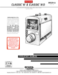
Commander™ 300
For use with machines having Code Numbers:
August, 2001
10469, 10642 (Standard),
10470, 10643 (Deluxe)
Safety Depends on You
Lincoln arc welding and cutting
equipment is designed and built
with safety in mind. However, your
overall safety can be increased by
proper installation ... and thoughtful
operation on your part. DO NOT
INSTALL, OPERATE OR REPAIR
THIS EQUIPMENT WITHOUT
READING THIS MANUAL AND
THE SAFETY PRECAUTIONS
CONTAINED THROUGHOUT. And,
most importantly, think before you
act and be careful.
Date of Purchase:
Serial Number:
Code Number:
Model:
Where Purchased:
OPERATOR’S MANUAL
Copyright © 2001 Lincoln Global Inc.
• World's Leader in Welding and Cutting Products •
• Sales and Service through Subsidiaries and Distributors Worldwide •
Cleveland, Ohio 44117-1199 U.S.A. TEL: 216.481.8100 FAX: 216.486.1751 WEB SITE: www.lincolnelectric.com
i
i
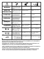
SAFETY
WARNING
CALIFORNIA PROPOSITION 65 WARNINGS
For Gasoline Engines: The engine exhaust from
For Diesel Engines: Diesel engine exhaust and
this product contains chemicals known to the
some of its constituents are known to the State
State of California to cause cancer, birth defects,
of California to cause cancer, birth defects, and
or other reproductive harm.
other reproductive harm.
ARC WELDING CAN BE HAZARDOUS. PROTECT YOURSELF AND OTHERS FROM POSSIBLE SERIOUS INJURY OR DEATH.
KEEP CHILDREN AWAY. PACEMAKER WEARERS SHOULD CONSULT WITH THEIR DOCTOR BEFORE OPERATING.
Read and understand the following safety highlights. For additional safety information, it is strongly recommended that you purchase a copy of “Safety in Welding & Cutting - ANSI Standard Z49.1” from the American Welding Society, P.O. Box 351040,
Miami, Florida 33135 or CSA Standard W117.2-1974. A Free copy of “Arc Welding Safety” booklet E205 is available from the
Lincoln Electric Company, 22801 St. Clair Avenue, Cleveland, Ohio 44117-1199.
BE SURE THAT ALL INSTALLATION, OPERATION, MAINTENANCE AND REPAIR PROCEDURES ARE
PERFORMED ONLY BY QUALIFIED INDIVIDUALS.
FOR ENGINE
powered equipment.
1.h. To avoid scalding, do not remove the
radiator pressure cap when the engine is
hot.
1.a. Turn the engine off before troubleshooting and maintenance
work unless the maintenance work requires it to be running.
____________________________________________________
1.b. Operate engines in open, well-ventilated
areas or vent the engine exhaust fumes
outdoors.
____________________________________________________
1.c. Do not add the fuel near an open flame welding arc or when the engine is running. Stop
the engine and allow it to cool before refueling to prevent spilled fuel from vaporizing on
contact with hot engine parts and igniting. Do
not spill fuel when filling tank. If fuel is spilled,
wipe it up and do not start engine until fumes
have been eliminated.
____________________________________________________
1.d. Keep all equipment safety guards, coversand devices in position and in good repair.Keep hands, hair, clothing and tools
away from V-belts, gears, fans and all other moving parts
when starting, operating or repairing equipment.
____________________________________________________
1.e. In some cases it may be necessary to remove safety
guards to perform required maintenance. Remove
guards only when necessary and replace them when the
maintenance requiring their removal is complete.
Always use the greatest care when working near moving
parts.
___________________________________________________
1.f. Do not put your hands near the engine fan. Do
not attempt to override the governor or idler
by pushing on the throttle control rods while
the engine is running.
ELECTRIC AND
MAGNETIC FIELDS
may be dangerous
2.a. Electric current flowing through any conductor causes
localized Electric and Magnetic Fields (EMF). Welding
current creates EMF fields around welding cables and
welding machines
2.b. EMF fields may interfere with some pacemakers, and
welders having a pacemaker should consult their physician
before welding.
2.c. Exposure to EMF fields in welding may have other health
effects which are now not known.
2.d. All welders should use the following procedures in order to
minimize exposure to EMF fields from the welding circuit:
2.d.1. Route the electrode and work cables together - Secure
them with tape when possible.
2.d.2. Never coil the electrode lead around your body.
2.d.3. Do not place your body between the electrode and
work cables. If the electrode cable is on your right
side, the work cable should also be on your right side.
2.d.4. Connect the work cable to the workpiece as close as
possible to the area being welded.
___________________________________________________
1.g. To prevent accidentally starting gasoline engines while
turning the engine or welding generator during maintenance
work, disconnect the spark plug wires, distributor cap or
magneto wire as appropriate.
2.d.5. Do not work next to welding power source.
Mar ‘95
ii
ii
SAFETY
ELECTRIC SHOCK can kill.
ARC RAYS can burn.
3.a. The electrode and work (or ground) circuits
are electrically “hot” when the welder is on.
Do not touch these “hot” parts with your bare
skin or wet clothing. Wear dry, hole-free
gloves to insulate hands.
4.a. Use a shield with the proper filter and cover
plates to protect your eyes from sparks and
the rays of the arc when welding or observing
open arc welding. Headshield and filter lens
should conform to ANSI Z87. I standards.
3.b. Insulate yourself from work and ground using dry insulation.
Make certain the insulation is large enough to cover your full
area of physical contact with work and ground.
4.b. Use suitable clothing made from durable flame-resistant
material to protect your skin and that of your helpers from
the arc rays.
In addition to the normal safety precautions, if welding
must be performed under electrically hazardous
conditions (in damp locations or while wearing wet
clothing; on metal structures such as floors, gratings or
scaffolds; when in cramped positions such as sitting,
kneeling or lying, if there is a high risk of unavoidable or
accidental contact with the workpiece or ground) use
the following equipment:
• Semiautomatic DC Constant Voltage (Wire) Welder.
• DC Manual (Stick) Welder.
• AC Welder with Reduced Voltage Control.
4.c. Protect other nearby personnel with suitable, non-flammable
screening and/or warn them not to watch the arc nor expose
themselves to the arc rays or to hot spatter or metal.
3.c. In semiautomatic or automatic wire welding, the electrode,
electrode reel, welding head, nozzle or semiautomatic
welding gun are also electrically “hot”.
3.d. Always be sure the work cable makes a good electrical
connection with the metal being welded. The connection
should be as close as possible to the area being welded.
3.e. Ground the work or metal to be welded to a good electrical
(earth) ground.
3.f. Maintain the electrode holder, work clamp, welding cable and
welding machine in good, safe operating condition. Replace
damaged insulation.
3.g. Never dip the electrode in water for cooling.
3.h. Never simultaneously touch electrically “hot” parts of
electrode holders connected to two welders because voltage
between the two can be the total of the open circuit voltage
of both welders.
3.i. When working above floor level, use a safety belt to protect
yourself from a fall should you get a shock.
3.j. Also see Items 6.c. and 8.
FUMES AND GASES
can be dangerous.
5.a. Welding may produce fumes and gases
hazardous to health. Avoid breathing these
fumes and gases.When welding, keep
your head out of the fume. Use enough
ventilation and/or exhaust at the arc to keep
fumes and gases away from the breathing zone. When
welding with electrodes which require special
ventilation such as stainless or hard facing (see
instructions on container or MSDS) or on lead or
cadmium plated steel and other metals or coatings
which produce highly toxic fumes, keep exposure as
low as possible and below Threshold Limit Values (TLV)
using local exhaust or mechanical ventilation. In
confined spaces or in some circumstances, outdoors, a
respirator may be required. Additional precautions are
also required when welding on galvanized steel.
5.b. Do not weld in locations near chlorinated hydrocarbon vapors
coming from degreasing, cleaning or spraying operations.
The heat and rays of the arc can react with solvent vapors to
form phosgene, a highly toxic gas, and other irritating
products.
5.c. Shielding gases used for arc welding can displace air and
cause injury or death. Always use enough ventilation,
especially in confined areas, to insure breathing air is safe.
5.d. Read and understand the manufacturer’s instructions for this
equipment and the consumables to be used, including the
material safety data sheet (MSDS) and follow your
employer’s safety practices. MSDS forms are available from
your welding distributor or from the manufacturer.
5.e. Also see item 1.b.
Mar ‘95
iii
iii
SAFETY
WELDING SPARKS can
cause fire or explosion.
6.a. Remove fire hazards from the welding area.
If this is not possible, cover them to prevent
the welding sparks from starting a fire.
Remember that welding sparks and hot
materials from welding can easily go through small cracks
and openings to adjacent areas. Avoid welding near
hydraulic lines. Have a fire extinguisher readily available.
6.b. Where compressed gases are to be used at the job site,
special precautions should be used to prevent hazardous
situations. Refer to “Safety in Welding and Cutting” (ANSI
Standard Z49.1) and the operating information for the
equipment being used.
6.c. When not welding, make certain no part of the electrode
circuit is touching the work or ground. Accidental contact can
cause overheating and create a fire hazard.
6.d. Do not heat, cut or weld tanks, drums or containers until the
proper steps have been taken to insure that such procedures
will not cause flammable or toxic vapors from substances
inside. They can cause an explosion even though they have
been “cleaned”. For information, purchase “Recommended
Safe Practices for the Preparation for Welding and Cutting of
Containers and Piping That Have Held Hazardous
Substances”, AWS F4.1 from the American Welding Society
(see address above).
6.e. Vent hollow castings or containers before heating, cutting or
welding. They may explode.
6.f. Sparks and spatter are thrown from the welding arc. Wear oil
free protective garments such as leather gloves, heavy shirt,
cuffless trousers, high shoes and a cap over your hair. Wear
ear plugs when welding out of position or in confined places.
Always wear safety glasses with side shields when in a
welding area.
6.g. Connect the work cable to the work as close to the welding
area as practical. Work cables connected to the building
framework or other locations away from the welding area
increase the possibility of the welding current passing
through lifting chains, crane cables or other alternate circuits.
This can create fire hazards or overheat lifting chains or
cables until they fail.
6.h. Also see item 1.c.
CYLINDER may explode
if damaged.
7.a. Use only compressed gas cylinders
containing the correct shielding gas for the
process used and properly operating
regulators designed for the gas and
pressure used. All hoses, fittings, etc. should be suitable for
the application and maintained in good condition.
7.b. Always keep cylinders in an upright position securely
chained to an undercarriage or fixed support.
7.c. Cylinders should be located:
• Away from areas where they may be struck or subjected to
physical damage.
• A safe distance from arc welding or cutting operations and
any other source of heat, sparks, or flame.
7.d. Never allow the electrode, electrode holder or any other
electrically “hot” parts to touch a cylinder.
7.e. Keep your head and face away from the cylinder valve outlet
when opening the cylinder valve.
7.f. Valve protection caps should always be in place and hand
tight except when the cylinder is in use or connected for
use.
7.g. Read and follow the instructions on compressed gas
cylinders, associated equipment, and CGA publication P-l,
“Precautions for Safe Handling of Compressed Gases in
Cylinders,” available from the Compressed Gas Association
1235 Jefferson Davis Highway, Arlington, VA 22202.
FOR ELECTRICALLY
powered equipment.
8.a. Turn off input power using the disconnect
switch at the fuse box before working on
the equipment.
8.b. Install equipment in accordance with the U.S. National
Electrical Code, all local codes and the manufacturer’s
recommendations.
8.c. Ground the equipment in accordance with the U.S. National
Electrical Code and the manufacturer’s recommendations.
Mar ‘95
iv
iv
SAFETY
PRÉCAUTIONS DE SÛRETÉ
Pour votre propre protection lire et observer toutes les instructions
et les précautions de sûreté specifiques qui parraissent dans ce
manuel aussi bien que les précautions de sûreté générales suivantes:
Sûreté Pour Soudage A L’Arc
1. Protegez-vous contre la secousse électrique:
a. Les circuits à l’électrode et à la piéce sont sous tension
quand la machine à souder est en marche. Eviter toujours
tout contact entre les parties sous tension et la peau nue
ou les vétements mouillés. Porter des gants secs et sans
trous pour isoler les mains.
b. Faire trés attention de bien s’isoler de la masse quand on
soude dans des endroits humides, ou sur un plancher metallique ou des grilles metalliques, principalement dans
les positions assis ou couché pour lesquelles une grande
partie du corps peut être en contact avec la masse.
c. Maintenir le porte-électrode, la pince de masse, le câble de
soudage et la machine à souder en bon et sûr état defonctionnement.
d.Ne jamais plonger le porte-électrode dans l’eau pour le
refroidir.
e. Ne jamais toucher simultanément les parties sous tension
des porte-électrodes connectés à deux machines à souder parce que la tension entre les deux pinces peut être le
total de la tension à vide des deux machines.
f. Si on utilise la machine à souder comme une source de
courant pour soudage semi-automatique, ces precautions
pour le porte-électrode s’applicuent aussi au pistolet de
soudage.
2. Dans le cas de travail au dessus du niveau du sol, se protéger
contre les chutes dans le cas ou on recoit un choc. Ne jamais
enrouler le câble-électrode autour de n’importe quelle partie
du corps.
3. Un coup d’arc peut être plus sévère qu’un coup de soliel,
donc:
a. Utiliser un bon masque avec un verre filtrant approprié
ainsi qu’un verre blanc afin de se protéger les yeux du rayonnement de l’arc et des projections quand on soude ou
quand on regarde l’arc.
b. Porter des vêtements convenables afin de protéger la peau
de soudeur et des aides contre le rayonnement de l‘arc.
c. Protéger l’autre personnel travaillant à proximité au
soudage à l’aide d’écrans appropriés et non-inflammables.
4. Des gouttes de laitier en fusion sont émises de l’arc de
soudage. Se protéger avec des vêtements de protection libres
de l’huile, tels que les gants en cuir, chemise épaisse, pantalons sans revers, et chaussures montantes.
5. Toujours porter des lunettes de sécurité dans la zone de
soudage. Utiliser des lunettes avec écrans lateraux dans les
zones où l’on pique le laitier.
6. Eloigner les matériaux inflammables ou les recouvrir afin de
prévenir tout risque d’incendie dû aux étincelles.
7. Quand on ne soude pas, poser la pince à une endroit isolé de
la masse. Un court-circuit accidental peut provoquer un
échauffement et un risque d’incendie.
8. S’assurer que la masse est connectée le plus prés possible de
la zone de travail qu’il est pratique de le faire. Si on place la
masse sur la charpente de la construction ou d’autres endroits
éloignés de la zone de travail, on augmente le risque de voir
passer le courant de soudage par les chaines de levage,
câbles de grue, ou autres circuits. Cela peut provoquer des
risques d’incendie ou d’echauffement des chaines et des
câbles jusqu’à ce qu’ils se rompent.
9. Assurer une ventilation suffisante dans la zone de soudage.
Ceci est particuliérement important pour le soudage de tôles
galvanisées plombées, ou cadmiées ou tout autre métal qui
produit des fumeés toxiques.
10. Ne pas souder en présence de vapeurs de chlore provenant
d’opérations de dégraissage, nettoyage ou pistolage. La
chaleur ou les rayons de l’arc peuvent réagir avec les vapeurs
du solvant pour produire du phosgéne (gas fortement toxique)
ou autres produits irritants.
11. Pour obtenir de plus amples renseignements sur la sûreté, voir
le code “Code for safety in welding and cutting” CSA Standard
W 117.2-1974.
PRÉCAUTIONS DE SÛRETÉ POUR
LES MACHINES À SOUDER À
TRANSFORMATEUR ET À
REDRESSEUR
1. Relier à la terre le chassis du poste conformement au code de
l’électricité et aux recommendations du fabricant. Le dispositif
de montage ou la piece à souder doit être branché à une
bonne mise à la terre.
2. Autant que possible, I’installation et l’entretien du poste seront
effectués par un électricien qualifié.
3. Avant de faires des travaux à l’interieur de poste, la debrancher à l’interrupteur à la boite de fusibles.
4. Garder tous les couvercles et dispositifs de sûreté à leur
place.
Mar. ‘93
v
v
Thank You
for selecting a QUALITY product by Lincoln Electric. We want you
to take pride in operating this Lincoln Electric Company product •••
as much pride as we have in bringing this product to you!
Please Examine Carton and Equipment For Damage Immediately
When this equipment is shipped, title passes to the purchaser upon receipt by the carrier. Consequently, Claims
for material damaged in shipment must be made by the purchaser against the transportation company at the
time the shipment is received.
Please record your equipment identification information below for future reference. This information can be found
on your machine nameplate.
Model Name & Number _____________________________________
Code & Serial Number _____________________________________
Date of Purchase
_____________________________________
Whenever you request replacement parts for or information on this equipment always supply the information you
have recorded above.
Read this Operators Manual completely before attempting to use this equipment. Save this manual and keep it
handy for quick reference. Pay particular attention to the safety instructions we have provided for your protection.
The level of seriousness to be applied to each is explained below:
WARNING
This statement appears where the information must be followed exactly to avoid serious personal injury or
loss of life.
CAUTION
This statement appears where the information must be followed to avoid minor personal injury or damage to
this equipment.
vi
vi
TABLE OF CONTENTS
Page
Safety .........................................................................................................................i-iv
Installation .......................................................................................................Section A
Technical Specifications ........................................................................................A-1
Safety Precautions.................................................................................................A-2
Location/ Ventilation...............................................................................................A-2
Storing.............................................................................................................A-2
Stacking...........................................................................................................A-2
Angle of Operation ..........................................................................................A-2
Lifting...............................................................................................................A-3
High Altitude Operation ...................................................................................A-3
Towing .............................................................................................................A-3
Pre-Operation Engine Service...............................................................................A-4
Oil....................................................................................................................A-4
Fuel .................................................................................................................A-4
Fuel Cap..........................................................................................................A-4
Engine Cooling System...................................................................................A-4
Battery Connection .........................................................................................A-4
Muffler .............................................................................................................A-5
Spark Arrester .................................................................................................A-5
High Frequency Generators for TIG Applications..................................................A-5
Remote Control .....................................................................................................A-5
Welding Terminals .................................................................................................A-5
Welding Output Cables ...................................................................................A-6
Machine Grounding ...............................................................................................A-6
Auxiliary Power Receptacles .................................................................................A-6
Standby Power Connections .................................................................................A-6
Connection of Lincoln Electric Wire Feeders ........................................................A-8
Operation .........................................................................................................Section B
Safety Instructions .................................................................................................B-1
General Description...............................................................................................B-1
Recommended Applications ...........................................................................B-1
Design Features and Advantages...................................................................B-1
Welding Capability ..........................................................................................B-2
Controls and Settings ............................................................................................B-3
Engine Controls...............................................................................................B-3
Welder Controls ..............................................................................................B-5
Auxiliary Power Controls .................................................................................B-5
Engine Operation...................................................................................................B-6
Starting the Engine .........................................................................................B-6
Stopping the Engine........................................................................................B-6
Break-In Period ...............................................................................................B-7
Typical Fuel Consumption ...............................................................................B-7
Welder Operation...................................................................................................B-7
Stick Welding...................................................................................................B-7
TIG Welding ....................................................................................................B-7
Wire Feed (Constant Voltage) Welding ...........................................................B-9
Auxiliary Power Operation ...................................................................................B-10
Simultaneous Welding and Auxiliary Power Loads .......................................B-10
COMMANDER 300
vii
vii
TABLE OF CONTENTS
Accessories .....................................................................................................Section C
Optional Field Installed Accessories .....................................................................C-1
Recommended Optional Equipment .....................................................................C-1
High Frequency Generators For TIG Applications ................................................C-1
Maintenance ....................................................................................................Section D
Safety Precautions ................................................................................................D-1
Routine and Periodic Maintenance .......................................................................D-1
Engine Maintenance..............................................................................................D-1
Air Filter...........................................................................................................D-1
Fuel Filters ......................................................................................................D-2
Cooling System...............................................................................................D-2
Cooling Blower Belt.........................................................................................D-2
Battery Handling .............................................................................................D-3
Nameplates/Warning Decals Maintenance ...........................................................D-3
Welder/Generator Maintenance ............................................................................D-3
Storage ...........................................................................................................D-3
Cleaning..........................................................................................................D-3
Brush Removal and Replacement ..................................................................D-3
Engine Maintenance Components ........................................................................D-4
Troubleshooting ..............................................................................................Section E
Diagrams and Dimension Print......................................................................Section F
Parts List ......................................................................................................P334 Series
COMMANDER 300
A-1
A-1
INSTALLATION
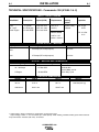
TECHNICAL SPECIFICATIONS - Commander 300 (K1585-1 & -2)
INPUT - DIESEL ENGINE
Make/Model
Description
Speed (RPM)
Displacement
Starting
System
Capacities
Deutz
F3L 1011F
Diesel Engine
3 cylinder
31 HP(23 kw)
@ 1800 RPM
High Idle 1900
Low Idle 1400
Full Load 1800
125 cu. in
(2.05 L)
12VDC battery
& Starter
Fuel: 25 gal.
94.6 L
Bore x Stroke
Oil: 6.3 Qts.
6.0 L
3.89” x 4.13”
(99mm x 105mm)
RATED OUTPUT - WELDER
Duty Cycle
Welding Output
Volts at Rated Amps
100%
300 amps (DC multi-purpose)
32 volts
60%
375 amps (DC multi-purpose)
34 volts
OUTPUT - WELDER AND GENERATOR
Welding Range
Open Circuit Voltage
Auxiliary Power1
30 - 300 Amps
87 Max OCV
5 Ranges
@1900 RPM
120/240 VAC
10,000 Watts, 60 Hz.
100% Duty Cycle
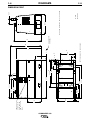
PHYSICAL DIMENSIONS
HEIGHT2
WIDTH
DEPTH
42.0 in.
31.5 in.
63.1 in.
1066.8 mm
800.1 mm
1602.7 mm
WEIGHT
1325 lbs.(601 kg)
1. Output rating in watts is equivalent to volt-amperes at unity power factor.
Output voltage is within +/- 10% at all loads up to rated capacity. When welding, available auxiliary power will be reduced.
2. Top of Enclosure. Add 8.9” (226.1mm) for exhaust.
COMMANDER 300
A-2
A-2
INSTALLATION
Read this entire installation section before you
start installation.
LOCATION/VENTILATION
The welder should be located to provide an unrestricted
flow of clean, cool air to the cooling air inlets and to avoid
restricting the cooling air outlets. Also, locate the welder
so that the engine exhaust fumes are properly vented to
an outside area.
SAFETY PRECAUTIONS
WARNING
Do not attempt to use this equipment until you have
thoroughly read all operating and maintenance manuals supplied with your machine. They include important safety precautions, detailed engine starting,
operating and maintenance instructions and parts
lists.
ELECTRIC SHOCK can kill.
•Do not touch electrically live parts such
as output terminals or internal wiring.
•Insulate yourself from the work and
ground.
•Always wear dry insulating gloves.
-----------------------------------------------------------------------ENGINE EXHAUST can kill.
•Use in open, well ventilated areas or
vent exhaust outside
•Do not stack anything near the engine.
-----------------------------------------------------------------------MOVING PARTS can injure.
•Do not operate with doors open or
guards off.
CAUTION
DO NOT MOUNT OVER COMBUSTIBLE SURFACES.
Where their is a combustible surface directly under stationary or fixed electrical equipment, that surface shall be
covered with a steel plate at least .06”(1.6mm) thick,
which shall extend not less than 5.90” (150mm) beyond
the equipment on all sides.
STORING
1. Store the machine in a cool, dry place when it is not
in use. Protect it from dust and dirt. Keep it where
it can’t be accidentally damaged from construction
activities, moving vehicles, and other hazards.
2. Drain the engine oil and refill with fresh 10W30 oil.
Run the engine for about five minutes to circulate oil
to all the parts. See the MAINTENANCE section of
this manual for details on changing oil.
3. Remove the battery, recharge it, and adjust the electrolyte level. Store the battery in a dry, dark place.
4. If the engine is not used for a long period of time,
every two to three months run the engine for about
five minutes to keep it free from rust.
STACKING
•Stop engine before servicing.
•Keep away from moving parts
-----------------------------------------------------------------------Only qualified personnel should install, use or service
this equipment
Commander 300 machines cannot be stacked.
ANGLE OF OPERATION
To achieve optimum engine performance the
Commander 300 should be run in a level position. The
maximum angle of operation for the Deutz engine is 20
degrees in a direction to cause the control panel to be
angled up, 30 degrees for side to side tilting and for the
control panel to be angled down. If the engine is to be
operated at an angle, provisions must be made for
checking and maintaining the oil level at the normal
(FULL) oil capacity in the crankcase. When operating
the welder at an angle, the effective fuel capacity will
be slightly less than the specified 25 gallons.
COMMANDER 300
A-3
INSTALLATION
A-3
LIFTING
TOWING
The Commander lift bale should be used to lift the
machine. The Commander is shipped with the lift bale
retracted. Before attempting to lift the Commander the
lift bale must be secured in a raised position. Secure
the lift bale as follows:
The recommended trailer for use with this equipment
for road, in-plant and yard towing by a vehicle(1) is
Lincoln’s K953-1. If the user adapts a non-Lincoln trailer, he must assume responsibility that the method of
attachment and usage does not result in a safety hazard nor damage the welding equipment. Some of the
factors to be considered are as follows:
a. Open the engine compartment door.
b. Locate the 2 access holes on the upper middle
region of compartment wall just below the lift
bale.
1. Design capacity of trailer vs. weight of Lincoln
equipment and likely additional attachments.
2. Proper support of, and attachment to, the base of
the welding equipment so that there will be no
undue stress to the trailer’s framework.
c. Use the lifting strap to raise the lift bale to the full
upright position. This will align the mounting
holes on the lift bale with the access holes.
3. Proper placement of the equipment on the trailer to
insure stability side to side and front to back when
being moved and when standing by itself.
d. Secure the lift bale with 2 thread forming screws.
The screws are provided in the shipped loose
parts bag.
4. Typical conditions of use, such as travel speed,
roughness of surface on which the trailer will be
operated, and environmental conditions.
WARNING
FALLING EQUIPMENT can cause
injury.
5. Proper preventative maintenance of trailer.
•Do not lift this machine using lift bale if
it is equipped with a heavy accessory
such as a trailer or gas cylinder.
6. Conformance with federal, state and local laws.1
1
•Lift only with equipment of adequate
lifting capacity.
Consult applicable federal, state and local laws
regarding specific requirements for use on public highways.
•Be sure machine is stable when lifting.
------------------------------------------------------------------------
HIGH ALTITUDE OPERATION
At higher altitudes, output derating may be necessary. For
maximum rating, derate the welder output 5% for every 300
meters (984 ft.) above 1500 meters (4920 ft.). For output of
300A and below, derate the welder output 5% for every 300
meters (984 ft.) above 2100 meters (6888 ft.)
Contact a Deutz Service Representative for any engine
adjustments that may be required.
COMMANDER 300
A-4
A-4
INSTALLATION
PRE-OPERATION ENGINE SERVICE
ENGINE COOLING SYSTEM
READ the engine operating and maintenance instructions supplied with this machine.
The Deutz engine is air cooled by a belt driven axial
blower. The oil cooler and engine cooling fins should
be blown out with compressed air or steam to maintain
proper cooling (See the engine Owners Manual for procedures and frequency).
WARNING
•Keep hands away from the engine
muffler or HOT engine parts.
BATTERY CONNECTION
•Stop engine and allow to cool before
fueling.
WARNING
GASES FROM BATTERY can explode.
● Keep sparks, flame and cigarettes
away from battery.
•Do not smoke when fueling.
•Fill fuel tank at a moderate rate and do not overfill.
•Wipe up spilled fuel and allow fumes to clear before
starting engine.
•Keep sparks and flame away from tank.
------------------------------------------------------------------------
OIL
The Commander is shipped with the engine crankcase
filled with high quality SAE 10W-30 oil (API class CD or
better). Check the oil level before starting the engine. If it
is not up to the full mark on the dip stick, add oil as
required. Check the oil level every four hours of running
time during the first 35 running hours. Refer to the engine
Operator’s Manual for specific oil recommendations and
break-in information. The oil change interval is dependent
on the quality of the oil and the operating environment.
Refer to the engine Operator’s Manual for the proper service and maintenance intervals.
FUEL USE DIESEL FUEL ONLY
Fill the fuel tank with clean, fresh diesel fuel. The capacity of the fuel tank is 25 gallons (94.6 liters). See engine
Operator’s Manual for specific fuel recommendations.
The Commander 300 Deluxe is protected by a low fuel
shutdown to prevent the engine from running out of fuel.
The machine will indicate a low fuel condition by turning
on the low fuel light. A time of 30 minutes will elapse once
the low fuel light illuminates before the machine will shutdown. A restart of the machine will restart the timer to
allow the operator to override this feature. The amount of
reserve fuel remaining in the tank after the first shutdown
will vary from machine to machine. The operator must
determine the amount of fuel remaining before re-starting
the machine. Running out of fuel may require bleeding
the fuel injection pump.
NOTE: Before starting the engine, open the fuel shutoff
valve (pointer to be in line with hose).
FUEL CAP
Remove the plastic cap covering from the Fuel Tank
Filler neck and install the Fuel Cap.
To prevent EXPLOSION when:
● INSTALLING A NEW BATTERY — disconnect
negative cable from old battery first and
connect
to new battery last.
● CONNECTING A BATTERY CHARGER —
remove battery from welder by disconnecting negative cable first, then positive cable and battery
clamp. When reinstalling, connect
negative cable last. Keep well ventilated.
●
USING A BOOSTER — connect positive lead to
battery first then connect negative lead to negative
battery lead at engine foot.
BATTERY ACID can burn eyes and
skin.
● Wear gloves and eye protection and
be careful when working near battery.
● Follow instructions printed on battery.
-----------------------------------------------------------------------IMPORTANT: To prevent ELECTRICAL DAMAGE
WHEN:
a) Installing new batteries.
b) Using a booster.
Use correct polarity — Negative Ground.
The Commander is shipped with the negative battery
cable disconnected. Before you operate the machine,
make sure the Engine Switch is in the OFF position
and attach the disconnected cable securely to the negative (-) battery terminal.
Remove the insulating cap from the negative battery
terminal. Replace and tighten negative battery cable
terminal. NOTE: This machine is furnished with a wet
charged battery; if unused for several months, the battery may require a booster charge. Be sure to use the
correct polarity when charging the battery.
COMMANDER 300
A-5
INSTALLATION
MUFFLER
REMOTE CONTROL
Remove the plastic plug covering the muffler outlet
tube. Using the clamp provided secure the extension to
the outlet tube. This welder is supplied with an
adjustable rain cap for the muffler. Install the rain cap
using the clamp provided with the outlet facing away
from the direction in which this unit will be transported.
This will minimize the amount of water and debris
which could enter the muffler during transportation.
OUTPUT
SPARK ARRESTER
Some federal, state or local laws may require that
gasoline or diesel engines be equipped with exhaust
spark arresters when they are operated in certain locations where unarrested sparks may present a fire hazard. The standard muffler included with this welder
does not qualify as a spark arrester. When required by
local regulations, a suitable spark arrester, such as the
S24647 must be installed and properly maintained.
CAUTION
A-5
The Commander 300 is equipped with a 6 pin & 14-pin
connector. The 6 pin connector is for connecting the
K857 or K857-1 Remote Control (Optional) or in the
case of TIG welding applications, with the foot or hand
Amptrol. (K870 or K812 respectively).
The 14 pin connector is used to directly connect a wire
feeder or TIG Module (K930-1 or-2) control cable.
When remote output control is used, the output control
toggle switch is to be set at “Remote.”
NOTE: When using the 14 pin connector, if the wire
feeder has a built in power source output control, do
not connect anything to the 6 pin connector.
WELDING TERMINALS
The Commander is equipped with a toggle switch for
selecting "hot" welding terminals when in the "WELDING TERMINALS ALWAYS ON" position or "cold"
welding terminals when in the "WELDING TERMINALS REMOTELY CONTROLLED" position.
An incorrect arrester may lead to damage to the engine
or adversely affect performance.
------------------------------------------------------------------------
HIGH FREQUENCY GENERATORS
FOR TIG APPLICATIONS
The K799 Hi-Freq Unit and the K930-1 or-2 TIG
Module are suitable for use with the Commander 300.
The Commander 300 is equipped with the required
R.F. bypass circuitry for the connection of high frequency generating equipment. The high frequency
bypass network supplied with the K799 Hi-Freq Unit
does NOT need to be installed into the Commander
300.
The Commander 300 and any high frequency generating equipment must be properly grounded. See the
K799 Hi-Freq Unit and the K930-1 or-2 TIG Module
operating manuals for complete instructions on installation, operation, and maintenance.
COMMANDER 300
A-6
INSTALLATION
WELDING OUTPUT CABLES
With the engine off, route the electrode and work
cables thru the strain relief bracket provided on the
front of the base and connect to the terminals provided. These connections should be checked periodically
and tightened if necessary.
A-6
joints, or to the metal framework of a building which
has been effectively grounded. The U.S. National
Electrical Code lists a number of alternate means of
grounding electrical equipment. A machine grounding
stud marked with the
symbol is provided on the
front of the welder.
AUXILIARY POWER RECEPTACLES
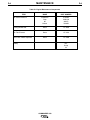
Listed in Table A.1 are copper cable sizes recommended for the rated current and duty cycle. Lengths
stipulated are the distance from the welder to work and
back to the welder again. Cable sizes are increased for
greater lengths primarily for the purpose of minimizing
cable voltage drop.
Table A.1 Combined Length of Electrode and Work
Cables.
AMPS
@100%
Duty Cycle
300
TOTAL COMBINED LENGTH OF ELECTRODE AND WORK CABLES
Up to 150 150-200 FT. 200-250 FT.
FT.
2/0 AWG
2/0 AWG
3/0 AWG
MACHINE GROUNDING
Because this portable engine driven welder creates its
own power, it is not necessary to connect its frame to
an earth ground, unless the machine is connected to
premises wiring (home, shop, etc.).
To prevent dangerous electric shock, other equipment
powered by this engine driven welder must:
a) be grounded to the frame of the welder using a
grounded type plug,
or
b) be double insulated.
When this welder is mounted on a truck or trailer, its
frame must be securely connected to the metal frame
of the vehicle. When this engine driven welder is connected to premises wiring such as that in a home or
shop, its frame must be connected to the system earth
ground. See further connection instructions in the section entitled “Standby Power Connections” as well as
the article on grounding in the latest U.S. National
Electrical Code and the local code.
In general, if the machine is to be grounded, it should
be connected with a #8 or larger copper wire to a solid
earth ground such as a metal water pipe going into the
ground for at least ten feet and having no insulated
The auxiliary power capacity of the Commander 300 is
10,000 watts of 60 Hz, single phase power. The auxiliary
power capacity rating in watts is equivalent to voltamperes at unity power factor. The maximum permissible current of the 240 VAC output is 44 A. The 240 VAC
output can be split to provide two separate 120 VAC outputs with a maximum permissible current of 44 A per output to two separate 120 VAC branch circuits. The output
voltage is within ± 10% at all loads up to rated capacity.
NOTE: The 120/240V receptacle has two 120V outlets
of different phases and cannot be paralleled.
The Commander has two 20* Amp-120VAC (5-20*R)
duplex receptacles and one 50 Amp-120/240 VAC (1450R) receptacle. The 120/240 VAC receptacle can be
split for single phase 120 VAC operation. The auxiliary
power receptacles should only be used with three wire
grounded type plugs or approved double insulated
tools with two wire plugs. The current rating of any plug
used with the system must be at least equal to the current capacity of the associated receptacle.
* 15 Amp receptacles for codes below 10500.
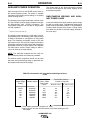
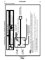
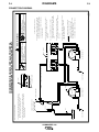
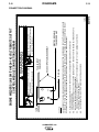
STANDBY POWER CONNECTIONS
The Commander 300 is suitable for temporary, standby or emergency power using the engine manufacturer’s recommended maintenance schedule.
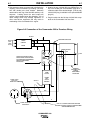
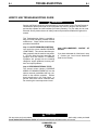
The Commander 300 can be permanently installed as
a standby power unit for 240 volt-3 wire, 44 amp service. Connections must be made by a licensed electrician who can determine how the 120/240 VAC power
can be adapted to the particular installation and comply with all applicable electrical codes. The following
information can be used as a guide by the electrician
for most applications. Refer to the connection diagram
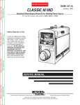
shown in Figure A.2.
1. Install the double-pole, double-throw switch between
the power company meter and the premises disconnect.
Switch rating must be the same or greater than the
customer’s premises disconnect and service over current protection.
COMMANDER 300
A-7
A-7
INSTALLATION
2. Take necessary steps to assure load is limited to the
capacity of the Commander by installing a 45 amp,
240 VAC double pole circuit breaker. Maximum
rated load for each leg of the 240 VAC auxiliary is 45
amperes. Loading above the rated output will
reduce output voltage below the allowable -10% of
rated voltage which may damage appliances or
other motor-driven equipment and may result in
overheating of the Commander 300 engine.
3. Install a 50 amp 120/240 VAC plug (NEMA Type 1450) to the double-pole circuit breaker using No. 6, 4
conductor cable of the desired length. (The 50 amp,
120/240 VAC plug is available in the optional K802R
plug kit.)
4. Plug this cable into the 50 Amp 120/240 Volt receptacle on the Commander 300 case front.
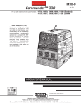
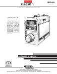
Figure A.2 Connection of the Commander 300 to Premises Wiring
240 VOLT
GROUNDED CONDUCTOR
POWER
240 Volt
60 Hz.
3-Wire
Service
120 VOLT
COMPANY
120 VOLT
METER
NEUTRAL
BUS
N
LOAD
DOUBLE POLE DOUBLE THROW
SWITCH RATING TO BE THE SAME
AS OR GREATER THAN PREMISES
SERVICE OVERCURRENT
PROTECTION.
GROUND
45AMP
240 VOLT
50 AMP, 120/240
VOLT PLUG
NEMA TYPE 14-50
240 VOLT
PREMISES
DISCONNECT AND
SERVICE
OVERCURRENT
PROTECTION
DOUBLE
POLE
CIRCUIT
BREAKER
GND
N
50 AMP, 120/240 VOLT
RECEPTACLE
NOTE: No. 8 COPPER CONDUCTOR CABLE SEE
NATIONAL ELECTRICAL CODE FOR ALTERNATE WIRE
SIZE RECOMMENDATIONS.
COMMANDER 300
A-8
A-8
INSTALLATION
CONNECTION OF LINCOLN
ELECTRIC WIRE FEEDERS
CAUTION
WARNING
Shut off welder before making any electrical connections.
------------------------------------------------------------------------
CONNECTION OF THE LN-25 TO THE
COMMANDER 300
The LN-25 with or without an external contactor may
be used with the Commander 300. See the appropriate connection diagram in the ACCESSORIES section.
NOTE: The LN-25 (K431) Remote Control Module and
(K432) Remote Cable are not recommended for use
with the Commander 300.
If you are using an LN-25 without an internal contactor,
the electrode will be energized when the Commander
300 is started.
-----------------------------------------------------------------------h. When the gun trigger is closed, the current sensing
circuit will cause the Commander 300 engine to go
to the high idle speed, the wire will begin to feed
and the welding process started. When welding is
stopped, the engine will revert to low idle speed
after approximately 12 seconds unless welding is
resumed.
CONNECTION OF LN-7 OR LN-8 TO THE
COMMANDER 300
a. Shut the welder off.
b. Connect the LN-7 or LN-8 per instructions on the
appropriate connection diagram in Section 4.
a. Shut the welder off.
b. For electrode Positive, connect the electrode cable
from the LN-25 to the “+” terminal of the welder and
work cable to the “-” terminal of the welder. For
electrode Negative, connect the electrode cable
from the LN-25 to the “-” terminal of the welder and
work cable to the “+” terminal of the welder.
c. Attach the single lead from the front of the LN-25 to
work using the spring clip at the end of the lead.
This is a sense lead to supply current to the wire
feeder motor; it does not carry welding current.
d. Set the SELECTOR switch to the “WIRE WELDING” position.
c. Set the “LOCAL /REMOTE” switch to “REMOTE” for
the LN-8 or LN-7 with a K857 (or K857-1) remote
voltage control cable attached; “LOCAL” for LN-7
with no remote voltage control.
d. Set the “WIRE FEEDER VOLTMETER” switch to
either “+” or “-” as required by the electrode being
used.
e. Set the “SELECTOR” switch to the “WIRE WELDING” position.
f. Adjust the “ARC CONTROL” knob to desired
Crispness. SOFT for MIG - CRISP for Innershield.
e. Set the “WELDING TERMINALS” switch to “WELDING TERMINALS ALWAYS ON”
g. Set the “WELDING TERMINALS” switch to the
“WELDING TERMINALS” REMOTELY CONTROLLED” position.
f. Adjust the “ARC CONTROL” knob to desired crispness. Generally, welding is best if the “ARC CONTROL” is set to SOFT for MIG and CRISP for
Innershield.
h. Set the “IDLE” switch to the “HIGH” position. When
not welding, the Commander 300 engine will be at
the low idle speed.
g. Set the “IDLE” switch to the “AUTO” position. When
not welding, the Commander 300 engine will be at
the low idle speed. If you are using an LN-25 with
an internal contactor, the electrode is not energized
until the gun trigger is closed.
COMMANDER 300
A-9
INSTALLATION
CONNECTION OF AN LN-23P WIRE
FEEDER TO THE COMMANDER 300
A-9
CONNECTION OF AN NA-3 AUTOMATIC
WELDING SYSTEM TO THE COMMANDER
300
a. Shut the welder off.
b. Connect the LN-23P as per instructions on the
appropriate connection diagram in Section 4.
(NOTE): When connecting an LN-23P to the
Commander 300, a K350-1 adapter kit must be
used.
c. Set the “VOLTMETER” switch to “-”.
d. Set the “SELECTOR” switch to “WIRE WELDING”
position.
For connection diagrams and instructions for connecting an NA-3 Welding System to the Commander 300,
refer to the NA-3 Welding System instruction manual.
The connection diagram for the LN-8 can be used for
connecting the NA-3.
CONNECTION OF AN LN-742 TO THE
COMMANDER 300 (FOR CODES ABOVE
10500 ONLY) (Requires optional K1597-1, 42 VAC
Transformer Kit, for codes below 10642).
e. Set the “WELDING TERMINALS” switch to “WELDING TERMINALS ALWAYS ON”.
a. Shut the welder off.
f. Set the ARC CONTROL to desired crispness. SOFT
for MIG - crisp for Innershield.
b. Connect the LN-742 per instructions on the appropriate connection diagram in the DIAGRAMS section.
g. Set the “LOCAL/ REMOTE” switch to the desired
setting depending upon where the power sources
output is being controlled from.
c. Set the “LOCAL/ REMOTE” switch to REMOTE.
h. Set the “IDLE” switch to the “HIGH” position. If you
are using an LN-23P with the K350-1 adapter kit,
the electrode is not energized until the gun trigger is
closed.
d. Set the “WIRE FEEDER VOLTMETER” switch to
either “+” or “-” as required by the electrode being
used.
e. Set the “SELECTOR” switch to the “WIRE WELDING-CV” position.
f. Adjust the “ARC CONTROL” knob to desired
Crispness. SOFT for MIG and CRISP for
Innershield.
g. Set the “WELDING TERMINALS” switch to the
“WELDING TERMINALS” REMOTELY CONTROLLED” position.
h. Set the “IDLE” switch to the “AUTO” position. When
not welding, the Commander 300 engine will be at
the low idle speed.
COMMANDER 300
B-1
OPERATION
B-1
OPERATING INSTRUCTIONS
GENERAL DESCRIPTION
Read and understand this entire section before operating your Commander 300.
The Commander 300 is a diesel engine-driven welding
power source. The machine uses a brush type alternating current generator for DC multi-purpose welding
and for 120/240 VAC auxiliary standby power. The
welding control system uses state of the art Chopper
Technology.
SAFETY INSTRUCTIONS
WARNING
Do not attempt to use this equipment until you have
thoroughly read all operating and maintenance manuals supplied with your machine. They include important safety precautions, detailed engine starting,
operating and maintenance instructions and parts
lists.
ELECTRIC SHOCK can kill.
•Do not touch electrically live parts such
as output terminals or internal wiring.
•Insulate yourself from the work and
ground.
•Always wear dry insulating gloves.
-----------------------------------------------------------------------ENGINE EXHAUST can kill.
The generator has a single sealed bearing for maintenance free service. The rotor is a copper wound design
with two slip rings and brushes. The stator is wound
entirely with heavy gauge copper wire and insulated
with NEMA class F insulation material. The stator is
then impregnated with three layers of high quality varnish. After the stator is assembled using tie bars, the
entire assembly covered with an environmentally protective coating. These measures insure trouble-free
operation in the harshest environments.
The fuel tank is made from high density polyethylene
and holds 25 gallons of diesel fuel. This will provide
enough fuel to run for 18 hours at full load.
The Deutz F3L-1011F engine is equipped with a standard, heavy duty, combination fuel filter/water separator element.
RECOMMENDED APPLICATIONS
•Use in open, well ventilated areas or
vent exhaust outside
•Do not stack anything near the engine.
-----------------------------------------------------------------------MOVING PARTS can injure.
•Do not operate with doors open or
guards off.
•Stop engine before servicing.
•Keep away from moving parts
-----------------------------------------------------------------------Only qualified personnel should operate this equipment.
ADDITIONAL SAFETY PRECAUTIONS
Always operate the welder with the hinged door closed
and the side panels in place as these provide maximum protection from moving parts and insure proper
cooling air flow.
WELDER
The Commander 300 provides excellent constant current DC
welding output for stick (SMAW) welding. The Commander
300 also provides excellent constant voltage DC welding output for MIG (GMAW) and Innershield (FCAW) welding.
GENERATOR
The Commander 300 provides smooth 120/240 VAC
output for auxiliary power and emergency standby
power.
DESIGN FEATURES AND ADVANTAGES
K1585-2 Commander 300 Deluxe Model Features
For Welding:
• Excellent DC multi-purpose welding for stick, MIG, TIG,
cored wire and arc gouging applications.
• 30 to 300 amps output in five slope controlled ranges
for out-of position and pipe electrodes, one constant
current output range for general purpose welding, and
one constant voltage range for MIG wire and cored
wire welding.
COMMANDER 300
B-2
OPERATION
• 100% duty cycle at 300 amps output and 60 % duty
cycle at 375 amps output.
• Dual 3-digit output meters are provided (optional on
K1585-1) for presetting the weld amperage or voltage
and displaying the actual amperage and voltage during
welding. The meters use superbrite L.E.D.'s for
improved readability in full sunlight.
• Standard remote control capability with 14 pin and 6 pin
connectors for easy connection of Lincoln remote control accessories.
• An internal "Solid State" contactor allows for the selection of "hot" or "cold" output terminals with a toggle
switch on the control panel.
B-2
• Indicator lights for low oil pressure, high oil temperature, engine alternator low output/broken belt and low
fuel level (on K1585-2 only).
• Automatic low fuel shutdown before running out of
fuel (K1585-2 only).
• Engine hour meter standard on all models.
• Extended range 25 gallon (94.6 l) fuel tank.
• Automatic idler reduces engine speed when not welding or drawing auxiliary power. This feature reduces
fuel consumption and extends engine life.
• Compact size fits crosswise in full size pick-up truck.
• “Arc Control”potentiometer in Wire and Stick modes for
precise adjustment of arc characteristics.
• Single side engine service.
• Advanced circuitry to prevent pop-outs in the five slope
modes.
• Copper alternator windings and high temperature
insulation for dependability and long life.
FOR AUXILIARY POWER
• 10,000 watts of 120/240 VAC, 60Hz auxiliary power.
• New paint system on case and base for outstanding
corrosion protection.
• Power for tools, 120/240 VAC lights, electric pumps
and for standby emergency power.
K1585-1 Commander 300 Standard Model
• Drive a 5 HP motor (provided it is started under no
load).
• Two 20* amp 120 VAC duplex receptacles for up to
40* amps of 120 VAC power.
* 15 Amp for each receptacle up to 30 Amp for codes below 10500 only.
• One 50 amp, 120/240 VAC dual voltage receptacle for
up to 44 amps of 240 VAC, and up to 44 amps per
side to separate branch circuits (not in parallel) of 120
VAC single phase auxiliary power. Allows easy connection to premises wiring.
• Weld and AC auxiliary power at the same time (within machine total capacity).
OTHER FEATURES
• Deutz 3-cylinder, air/oil cooled diesel engine.
Designed for long life, easy maintenance and excellent fuel economy.
• The K1585-1 is the standard version of the
Commander 300, and has all the features of the
K1585-2 Deluxe version except that there are no
gauges, low fuel light nor dual output meters. This
version does have fully functional engine protection
for low oil pressure, high oil temperature, and alternator output with associated lights.
• A field installed Dual Output Meter and Gauge Kit (K1596-1) is available for the K1585-1 Commander
300.The kit includes dual output meters, oil pressure
gauge, oil temperature gage, and alternator ammeter.
WELDING CAPABILITY
The Commander 300 is rated at 300 amps, 32 VDC at
100% duty cycle and 375 amps, 34 VDC at 60% duty
cycle. The maximum open circuit voltage at 1900 RPM
is 87 volts. The weld current is variable from 30 to 375
amps.
• Engine protection system shuts the engine down for
low oil pressure, high oil temperature or a broken
fan/engine alternator belt.
• Gauges for oil pressure, oil temperature, engine alternator output and fuel level.
COMMANDER 300
B-3
B-3
OPERATION
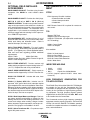
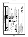
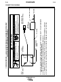
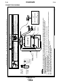
CONTROLS AND SETTINGS
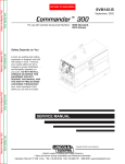
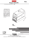
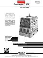
All welder and engine controls are located on the case front panel. Refer to Figure B.1 and the explanations that
follow.
Figure B.1 Case Front Panel Controls
1
9
10
9
4
3
2
5
OIL
OIL
TEMP
PRESS
6
7
8
0
0
0
0
00
HOURS
FUEL
AMPS
24
13
18
15
16
25
17
21
22
11
12
19
23
14
ENGINE CONTROLS (Items 1 through 8)
1.
RUNSTOP SWITCH
When placed in the “RUN” position, this switch energizes the fuel solenoid and other electric accessories.
When placed in the “STOP” position, the flow of fuel to
the injection pump is stopped to shut down the engine.
(Note: If the switch is left in the "RUN" position and the
engine is not running, the fuel solenoid will be engaged
for 15 seconds and then shut down. This is to protect
the battery from discharge. After 15 seconds, the Run
/ Stop switch must be toggled off then on before starting.)
3. FUEL LEVEL GAUGE AND LIGHT
(K1585-2 only) - Displays the level of
diesel fuel in the 25-gallon fuel tank. The
yellow light turns on when the fuel gage reaches the
reserve level. Once the reserve level is reached, the
engine protection system will shut down the engine
after 30 minutes of operation. The machine can be
restarted and operated for an additional 30 minutes
before the protection system will shut down the engine.
This ability to override the engine protection is to allow
the operator to “finish up” if necessary. The operator
must watch the fuel level closely to prevent running out
of fuel and having to bleed the system.
2. START PUSHBUTTON
Energizes the starter motor to crank the engine. With the
engine "Run / Stop" switch in the "Run" position, push and
hold the Start button to crank the engine; release as the
engine starts. Start button must be depressed for a minimum
of two seconds. Do not press while engine is running since
this can cause damage to the ring gear and/or starter motor.
COMMANDER 300
B-4
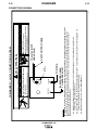
OPERATION
4. ENGINE TEMPERATURE GAUGE (K1585-2
Std., K1585-1 Opt.) AND LIGHT
The gauge displays the engine oil temperature. The
yellow temperature light remains off under normal
operating temperatures. If the light turns on, the engine
protection system will shut down the engine. Check for
restrictions at the engine cooling air inlets and outlets
(consult the engine Operator’s Manual). Check for
loose or disconnected leads at the temperature sender
located on the engine. Check engine cooling blower
belt. Also, check to be sure that the welder loads are
within the rating of the welder. The light will remain on
when the engine has been shut down due to an overtemperature condition.
5. OIL PRESSURE GAUGE (K1585-2 Std.,
K1585-1 Opt.) AND LIGHT
The gauge displays the engine oil pressure when the
engine is running. The yellow oil pressure light remains
off with proper oil pressure. If the light turns on, the
engine protection system will stop the engine. Check
for proper oil level and add oil if necessary. Check for
loose or disconnected leads at the oil pressure sender
located on the engine. The light will go on and stay on
when the RUN-STOP switch is switched to the “Run”
position with engine not running.
6. ENGINE ALTERNATOR AMMETER (K15852 Std., K1585-1 Opt.) AND LIGHT
The yellow engine alternator light is off when battery
charging system is functioning normally. If light turns
on, the engine protection system will shut down the
engine. Check the engine cooling blower belt. Also, the
alternator or the voltage regulator may not be operating correctly. The light may also come on due to a faulty
flashing circuit. The light will remain on when the
engine has been shut down due to a fault in the alternator, regulator, or the cooling blower belt.
c. When welding ceases or the AC power load is
turned off, a fixed time delay of approximately 12
seconds starts.
d. If the welding or AC power load is not restarted
before the end of the time delay, the idler reduces
the engine speed to low idle speed.
e. The engine will automatically return to high idle
speed when the welding load or A.C. power load
is reapplied.
Idler Operational exceptions
When the WELDING TERMINALS switch is in the
“Welding Terminals Remotely Controlled” position the
idler will operate as follows:
a. When the triggering device (Amptrol, Arc Start
Switch, etc.) is pressed the engine will accelerate
and operate at full speed provided a welding load is
applied within approximately 12 seconds.
• If the triggering device remains pressed but no welding load is applied within approximately 12 seconds
the engine will return to low idle speed.
• If the triggering device is released or welding ceases
the engine will return to low idle speed after approximately 12 seconds.
8. HOUR METER
The hour meter displays the total time that the engine
has been running. This meter is a useful indicator for
scheduling preventive maintenance.
7. IDLER SWITCH
Has two positions as follows:
A) In the “High” position
, the engine runs at
the high idle speed controlled by the governor.
B) In the “Auto”
ates as follows:
/
B-4
position, the idler oper-
a. When switched from “High” to “Auto” or after
starting the engine, the engine will operate at full
speed for approximately 12 seconds and then go
to low idle speed.
b. When the electrode touches the work or power is
drawn for lights or tools (approximately 100 Watts
minimum) the engine accelerates and operates
at full speed.
COMMANDER 300
B-5
OPERATION
WELDER CONTROLS (Items 9 through 14 )
9. OUTPUT
SELECTOR SWITCH & OUTPUT
CONTROL
These two controls allow you to select between various
welding output slopes and adjust the desired welding
output. Refer to Table B.1 for a description of how
these two controls work.
Table B.1 Output Range Switch and Output Control
Functions
Selector
1
Switch
Sloped Output for
Pipe Welding.
5 Range
Settings
60, 90, 150,
230, 300 (Max.
current on each
setting)
Constant Current
Output for
Fabrication and
General Purpose
Welding (This setting also used for
TIG)
1 Range setting
30-375 Amps
Constant Voltage
Output for MIG
Wire or CORED
WIRE Welding
1 Range setting
12 to 40 Volts
2
Control
Provides a fine
adjustment of
welding current
from
Min (1) to Max
(10) within each
range
Provides Fine
Voltage
Adjustment
1
If the SELECTOR switch is positioned between settings the previous setting is maintained until the switch is properly positioned on
a setting.
2
CONTROL also controls O.C.V. while in the 5 sloped output ranges.
10. DIGITAL OUTPUT METERS
The digital output meters are located in the center of
the control panel between the two large control knobs.
The meters allow the output current level to be set prior
to welding in stick mode, and voltage level to be set
prior to welding in the wire modes. During the welding
process the meters display the actual output current
and voltage, within +1%, -10% accuracy.
11. WELDING TERMINALS SWITCH
The toggle switch on the control panel labeled
“Welding Terminals Always On” and “Welding
Terminals Remotely Controlled”: is used to control the
operation of the “solid state contactor” which allows for
the selection of “Hot” or “Cold” welding terminals.
B-5
With the switch in the “Welding Terminals Always On”
position the contactor is closed and the welding terminals are always “Hot”.
With the switch in the “Welding Terminals Remotely
Controlled” position the contactor operation is controlled by an Amptrol, Arc Start Switch or some other
type of triggering device through the use of a control
cable connected to the 14-pin MS connector.
When the triggering device is pressed the contactor is
closed and the welding terminals are “Hot”.
When the triggering device is released the contactor is
opened and the welding terminals are “Cold”.
12. LOCAL
/REMOTE
SWITCH
The toggle switch on the control panel labeled
“Local/Remote” gives the operator the option of controlling the output at the welder control panel or at a
remote station.
For remote control the toggle switch is set in the
“Remote” position.
For control at the welder control panel, the toggle
switch is set in the “Local” position.
13. 6 - PIN CONNECTOR
The 6-pin connector located on the control panel
allows for connection of interfacing equipment.
14. WELD OUTPUT TERMINALS + AND These 1/2 - 13 studs with flange nuts provide welding
connection points for the electrode and work cables.
For positive polarity welding the electrode cable connects to the “+” terminal and the work cable connects
to this “-” terminal. For negative polarity welding the
work cable connects to the “+” terminal and the electrode cable connects to this “-” terminal.
AUXILIARY POWER CONTROLS
(Items 15 - 19 )
15. 120/240VAC RECEPTACLE
This is a 120/240VAC (14-50R) receptacle that provides 240VAC or can be split for 120VAC single phase
auxiliary power. This receptacle has a 50 amp rating.
Refer to the AUXILIARY POWER RECEPTACLES section in the installation chapter for further information
about this receptacle. Also refer to the AUXILIARY
POWER OPERATION section later in this chapter.
16. 50 AMP CIRCUIT BREAKERS
These circuit breakers provide separate overload current protection for each 120V circuit at the 240V receptacle.
COMMANDER 300
B-6
OPERATION
17. 120VAC RECEPTACLES
These two 120VAC (5-20*R) receptacles provide 120VAC
for auxiliary power. These receptacles have a 40* amp
total rating. Refer to the AUXILIARY POWER RECEPTACLES section in the installation chapter for further information about these receptacles. Also refer to the AUXILIARY POWER OPERATION section later in this chapter.
B-6
ENGINE OPERATION
STARTING THE ENGINE
* 15 Amps per receptacle up to 30 Amps total for codes below 10500 only.
1. Open the engine compartment door and check that
the fuel shutoff valve located to the left of the fuel filter housing is in the open position (lever to be in line
with the hose).
18. 20* AMP CIRCUIT BREAKERS
These circuit breakers provide separate overload current protection for each 120V receptacle.
2. Check for proper oil level on the oil dipstick. Close
engine compartment door.
3. Remove all plugs connected to the AC power receptacles.
* 15 Amps for codes below 10500 only.
4. Set IDLER switch to “AUTO”.
19. GROUND STUD
Provides a connection point for connecting the
machine case to earth ground for the safest grounding
procedure. Refer to “MACHINE GROUNDING” in the
Installation chapter for proper machine grounding
information.
5. Set the RUN/STOP switch to “RUN”. Observe that all
engine protection lights momentarily turn on, some lights
may turn off before starting. Check the fuel gauge
(K1585-2 only) to make sure that there is an adequate
fuel level.
21. 15 AMP CIRCUIT BREAKER
This circuit breaker provides overload protection for the
120 VAC in the 14-pin connector.
22. VOLTMETER +/- SWITCH
Changes the polarity display on the wire feeder.
23. 15 AMP CIRCUIT BREAKER
This circuit breaker provides overload protection for the
42 VAC in the 14-pin connector.
6. Press and hold the engine START button for a minimum
of 2 seconds.
7. Release the engine START button when the engine starts.
8. Check that the indicator lights are off. If the LOW FUEL light is
on (K1585-2 only) , the engine will shutdown 30 minutes after
starting. If any other indicator light is on after starting, the
engine will shutdown in a few seconds. Investigate any indicated problem.
9. Allow the engine to warm up at low idle speed for several
minutes before applying a load and/or switching to high
idle. Allow a longer warm up time in cold weather.
24. 14 - PIN CONNECTOR
For quick connection of interfacing equipment.
25. ARC CONTROL
The “ARC CONTROL” potentiometer is active in two
modes: “STICK / TIG “ and “WIRE WELDING” with different purposes in each mode.
“STICK / TIG” mode: In this mode, the “ARC CONTROL” knob sets the short circuit current during stick
welding. Increasing the number from 1 to 10 increases
the short circuit current. This prevents sticking of the
electrode to the plate at low welding current settings.
This also increases spatter. It is recommended that the
control be set to the minimum number without electrode sticking.
“WIRE WELDING” mode: In this mode increasing the
number from 1 to 10 changes the arc from soft and
washed in to crisp and narrow. It acts as an inductance
control. The proper setting depends on the application
and operator preference.
In general, Mig welding performs best in the “SOFT”
range and Innershield in the “CRISP” range.
COLD WEATHER STARTING
With a fully charged battery and the proper weight oil,
the engine should start satisfactorily even down to
about 0°F. With the above and the optional ether
starter kit (K887-1), the engine should start satisfactorily down to about -20°F. With the above and an oil pan
preheating system* the engine should start satisfactorily down to about -30°F. With the above and a battery
warmer*, the engine should start satisfactorily down to
about -40°F.
* Contact your local Lincoln Electric Representative for
suggested after-market kits.
STOPPING THE ENGINE
1. Switch the RUN/STOP switch to “STOP”. This turns
off the voltage supplied to the shutdown solenoid. A
backup shutdown can be accomplished by shutting
off the fuel valve located on the fuel line.
COMMANDER 300
B-7
OPERATION
BREAK-IN PERIOD
The engine used to supply power for your welder is a
heavy duty, industrial engine. It is designed and built
for rugged use. It is very normal for any engine to use
small quantities of oil until the break-in is accomplished. Check the oil level twice a day during the
break-in period (about 200 running hours).
IMPORTANT
IN ORDER TO ACCOMPLISH THIS BREAK-IN, THE
UNIT SHOULD BE SUBJECTED TO HEAVY LOADS,
WITHIN THE RATING OF THE MACHINE. AVOID
LONG IDLE RUNNING PERIODS.
TYPICAL FUEL CONSUMPTION
Refer to Table B.2 for typical fuel consumption of the
Commander 300’s Engine for various operating scenarios.
Table B.2 Deutz F3L 912 Engine Fuel Consumption
Deutz F3L 1011 Running Time for
29 Hp
25 gallons
@ 1800 RPM
(Hours)
Low Idle - No
.27 gallons/hour
Load 1400 RPM (1.02 liters/hour)
92.5
High Idle - No
.48 gallons/hour
Load 1900 RPM ( 1.81 liters/hour)
52
DC CC Weld
1.34 gallons/hour
Output 300
( 5.07 liters/hour)
Amps @ 32 Volts
18.6
Auxiliary Power
10,000 VA
18.9
1.32 gallons/hour
(5.00 liters/hour)
B-7
trolled settings are intended for “out-of-position” welding, including pipe welding, where the operator would
like to control the current level by changing the arc
length.
PIPE WELDING
The Commander 300 is equipped with special circuitry
to minimize pop-outs in the five slope modes at any
open circuit voltage.
For a soft arc characteristic, set the "SELECTOR"
Switch to the lowest setting that still provides the current you need and set the "CONTROL" near maximum.
For example: to obtain 140 amps and a soft arc, set
the " SELECTOR" Switch to the "150 MAX" position
and then adjust the " CONTROL" for 140 amps.
When a forceful "digging" arc is required, use a higher
setting and lower the open circuit voltage. For example:
to obtain 140 amps and a forceful arc, set the “ SELECTOR” to the "230 MAX" position and then adjust the "
CONTROL" to get 140 amps.
CONSTANT CURRENT (CC) WELDING
The most clockwise position of “30 to 375" the
"SELECTOR" Switch is designed for horizontal welds
with all types of electrodes especially low hydrogen.
The " CONTROL" adjusts the full range of 30 to 375
amps. This setting provides a soft, constant current arc.
If a more forceful arc is desired, then select the proper
range from the slope controlled current ranges.
In the CC mode, sticking can be prevented by adjusting the “ARC CONTROL”. Turning this control clockwise, increases the short circuit current, thus preventing sticking. This is another way of increasing arc force.
TIG WELDING
The Commander 300 can be used in a wide variety of
DC Tungsten Inert Gas (TIG) welding applications.
When used with the K930-1 or -2 TIG module or K799
Hi-freq unit, ratings are limited to 375A at a 20% duty
cycle, 300A at a 60% duty cycle and 250A at a 80%
duty cycle.
WELDER OPERATION
STICK WELDING
The Commander 300 can be used with a broad range
of DC stick electrodes.
The SELECTOR switch provides five overlapping
slope controlled current ranges. The CONTROL
adjusts the current from minimum to maximum within
each range. Voltage is also controlled by the CONTROL in the slope controlled setting. These slope con-
COMMANDER 300
B-8
B-8
OPERATION
Table B.3 TYPICAL CURRENT RANGES
Tungsten
Electrode
Diameter
in. (mm)
DCEN (-)
DCEP (+)
1%, 2%
Thoriated
Tungsten
1%, 2%
Thoriated
Tungsten
(1)
(2)
FOR TUNGSTEN ELECTRODES
Approximate Argon Gas Flow Rate
C.F.H. (l/min.)
Aluminum
Stainless Steel
TIG TORCH
Nozzle
Size (4), (5)
0 .010
0.020
0.040
(.25)
(.50)
(1.0)
2-15
5-20
15-80
(3)
(3)
(3)
3-8
5-10
5-10
(2-4)
(3-5)
(3-5)
3-8
5-10
5-10
(2-4)
(3-5)
(3-5)
#4, #5, #6
1/16
(1.6)
70-150
10-20
5-10
(3-5)
9-13
(4-6)
#5, #6
3/32
1/8
(2.4)
(3.2)
150-250
250-400
15-30
25-40
13-17
15-23
(6-8)
(7-11)
11-15
11-15
(5-7)
(5-7)
#6, #7, #8
5/32
3/16
1/4
(4.0)
(4.8)
(6.4)
400-500
500-750
750-1000
40-55
55-80
80-125
21-25
23-27
28-32
(10-12) 13-17
(11-13) 18-22
(13-15) 23-27
(6-8)
#8, #10
(8-10)
(11-13)
(1) When used with argon gas. The current ranges shown must be reduced when using argon/helium or pure helium
shielding gases.
(2) Tungsten electrodes are classified as follows by the American Welding Society (AWS):
Pure
EWP
1% Thoriated
EWTh-1
2% Thoriated
EWTh-2
Though not yet recognized by the AWS, Ceriated Tungsten is now widely accepted as a substitute for 2% Thoriated
Tungsten in AC and DC applications.
(3) DCEP is not commonly used in these sizes.
(4) TIG torch nozzle “sizes” are in multiples of 1/16ths of an inch:
# 4 = 1/4 in.
(6 mm)
# 5 = 5/16 in.
(8 mm)
# 6 = 3/8 in.
(10 mm)
# 7 = 7/16 in.
(11 mm)
# 8 = 1/2 in.
(12.5 mm)
#10 = 5/8 in.
(16 mm)
(5) TIG torch nozzles are typically made from alumina ceramic. Special applications may require lava nozzles, which are
less prone to breakage, but cannot withstand high temperatures and high duty cycles.
Commander 300 SETTINGS WHEN USING THE
K799 HI-FREQ UNIT
Commander 300 SETTINGS WHEN USING THE
K930-1 TIG MODULE
a. Set the SELECTOR switch to the “30-375 setting”
(STICK / TIG)
a. Set the SELECTOR switch to the 30-375 Setting
(STICK / TIG).
b. Set the IDLER switch to the “HIGH “ position.
b. Set the IDLER switch to the “AUTO “ position.
c. Set the LOCAL/REMOTE switch to the “REMOTE” position.
c. Set the LOCAL/REMOTE switch to the “REMOTE” position.
d. Set the WELDING TERMINALS switch to the “Welding
Terminals Always On” position. This will close the solid
state contactor and provide an always “hot” electrode.
d. Set the WELDING TERMINALS switch to the “Welding
Terminals Remotely Controlled” position. This will keep
the solid state contactor open and provide a “cold”
electrode until the triggering device (Amptrol or Arc
Start Switch) is pressed.
(Note: This is necessary because the K799 circuitry with
respect to the #2 and #4 leads does not provide the proper signal to open and close the solid state contactor in the
Commander 300).
COMMANDER 300
B-9
OPERATION
WIRE FEED (CONSTANT VOLTAGE) WELDING
Connect a wire feeder to the Commander 300 and set
welder controls according to the instructions listed earlier
in this section.
The Commander 300 in the ”WIRE WELDING” position,
permits it to be used with a broad range of flux cored wire
(Innershield and Outershield) electrodes and solid wires
for MIG welding (gas metal arc welding). Welding can be
finely tuned using the “ARC CONTROL”.
Some recommended Innershield electrodes are: NR-311,
NS-3M, NR-207, NR-203 Ni 1%, NR-204-H.
Recommended Outershield electrodes are: 0S-70, 0S71M.
Some recommended solid wires for MIG welding are: .035
(0.9 mm), .045 (1.1 mm) and .052 (1.3 mm), L-50 and L56, .035 (0.9 mm) and .045 (1.1 mm) Blue Max MIG 308
LS.
For any electrodes, including the above recommendations,
the procedures should be kept within the rating of the
machine. For additional electrode information, see Lincoln
publications N-675, GS-100 and GS-210.
COMMANDER 300
B-9
B-10
B-10
OPERATION
AUXILIARY POWER OPERATION
Start the engine and set the IDLER control switch to
the desired operating mode. Full power is available
regardless of the welding control settings, if no welding
current is being drawn.
The auxiliary power of the Commander consists of two
20Δ Amp-120VAC (5-20ΔR) duplex receptacles and one
50 Amp-120/240 VAC (14-50R) receptacle. The
120/240VAC receptacle can be split for single phase
120 VAC operation.
Δ
15 Amps for codes below 10500 only.
The current rating of any plug used with the system
must be at least equal to the current capacity of the
associated receptacle.
SIMULTANEOUS WELDING AND AUXILIARY POWER LOADS
It must be noted that the above auxiliary power ratings
are with no welding load. Simultaneous welding and
power loads are specified in table B.4. The permissible
currents shown assume that current is being drawn
from either the 120 VAC or 240 VAC supply (not both at
the same time).
The auxiliary power capacity is 10,000 watts of 60 Hz,
single phase power. The auxiliary power capacity rating
in watts is equivalent to volt-amperes at unity power
factor. The maximum permissible current of the 240
VAC output is 44 A. The 240 VAC output can be split to
provide two separate 120 VAC outputs with a maximum
permissible current of 44 A per output to two separate
120 VAC branch circuits. Output voltage is within ±
10% at all loads up to rated capacity.
NOTE: The 120/240V receptacle has two 120V outputs of different phases and cannot be paralleled.
The auxiliary power receptacles should only be used
with three wire grounded type plugs or approved double insulated tools with two wire plugs.
TABLE B.4 Commander 300 Simultaneous Welding and Power
Loads
Welding
Output Range
Setting
30-375
300
230
150
90
60
Welding Output
300A/32V
300A/32V
230A/30V
150A/29V
90A/27V
60A/25V
Permissible
Power - Watts
(Unity Power
Factor)
Permissible Auxiliary
Current in Amperes
@120 V ±10% * @ 240 V ±10%
400
400
3100
5650
7600
8500
3.3
3.3
26*
47**
63**
70**
1.6
1.6
13
23.5
31.5
35
* Each duplex receptacle is limited to 20Δ amps.
** Not to exceed 44 A per 120 VAC branch circuit when splitting the 240
VAC output.
COMMANDER 300
C-1
ACCESSORIES
C-1
OPTIONAL FIELD INSTALLED
ACCESSORIES
RECOMMENDED OPTIONAL EQUIPMENT
K802R POWER PLUG KIT - Provides a plug for each
receptacle. Use K802N for code numbers above
10500.
STICK
K704 Accessory Kit which includes:
• Electrode holder and cable.
• Ground clamp and cable.
• Headshield.
K802N POWER PLUG KIT - Provides four 120V plugs.
K857 28 ft. (8.5 m) or K857-1 100 ft. (30.4 m)
REMOTE CONTROL - Portable control provides same dial
range as the output control on the welder from a location up
to the specified length from the welder. Has convenient plug
for easy connection to the welder. The Commander 300 is
equipped with a 6 pin connector for connecting the remote
control and a toggle switch for selecting “LOCAL” output control or “REMOTE” output control.
K857 Remote Control Kit is optional for remote current control.
TIG
Magnum TIG Torch
Magnum Parts Kit and Argon gas
K930-ALL TIG Module (not required for scratch start
DC TIG welding)
K704 ACCESSORY SET - Includes 35 feet (10 m) of
electrode cable and 30 feet (9 m) of work cable, headshield, work clamp and electrode holder. Cable is
rated at 500 amps, 60% duty cycle.
K953-1 TWO WHEEL TRAILER - For road, in-plant
and yard towing. Road towing with optional fender &
light kit. (For highway use, consult applicable federal,
state and local laws regarding possible additional
requirements)
K953-1 Trailer
K958-1 Ball Hitch
K958-2 Lunette Eye Hitch K959-1 Fender & Light Kit
K965-1 Cable Storage Rack
K887-1 ETHER START KIT - Provides maximum cold
weather starting assistance for frequent starting below 10 oF
(-12.2 oC). Required Ether tank is not provided with kit.
S24647 SPARK ARRESTOR KIT - Easily mounts to
standard muffler. Approved by U.S.D.A. Forest Service.
K1604-1 OIL DRAIN KIT - Includes ball valve, hose
and clamp.
K1690-1 (1 Duplex) GFCI Kit - Includes one UL
approved 115V ground fault circuit interrupter duplex
type receptacle with cover and installation instructions.
Replaces the factory installed 115V duplex receptacle.
The receptacle of the GFCI duplex is rated at 20 amps,
the maximum total current from the GFCI duplex is limited to 20 amps. Two kits are required.
K1596-1 Dual Output Meters and Gauges - Dual output meters provide preset ability of voltage for wire
welding and current for stick welding. Measures b o t h
current and voltage when welding. Gauges include:
battery ammeter, engine temperature, and engine oil
pressure. Fuel gauge is not available in kit form.
K936-1 Control Cable
K870 Foot Amptrol
Also available:
K963-1/-2 Hand Amptrol
K814 Arc Start Switch
K937-22 Control Cable Extension
K937-45 Control Cable Extension
K844-1 Water Valve
WIRE FEED WELDING
•
•
•
•
LN-25
• LN-7
LN-23P
• LN-8
NA-3
• Spool Gun & K488 Module
LN-742 (requires optional K1597-1 42vac transformer kit).
HIGH FREQUENCY GENERATORS FOR
TIG APPLICATIONS
The K799 Hi-Freq Unit and the K930-ALL TIG Modules
are suitable for use with the Commander 300. The
Commander is equipped with the required R.F. bypass
circuitry for the connection of high frequency generating equipment. The high frequency bypass network
supplied with the K799 Hi-Freq Unit does NOT need
to be installed into the Commander.
The Commander and any high frequency generating
equipment must be properly grounded. See the K799
Hi-Freq Unit and the K930-All TIG Module operating
manuals for complete instructions on installation, operation, and maintenance.
K1597-1 42vac Transformer Kit. - For products requiring 42 VAC power source.
COMMANDER 300
D-1
D-1
MAINTENANCE
SAFETY PRECAUTIONS
ENGINE MAINTENANCE
WARNING
•Have a qualified technician do the maintenance
and troubleshooting work.
•Turn the engine off before working inside the
machine.
•Remove guards only when necessary and replace
them when the maintenance requiring their
removal is complete.
•Always use the greatest care when working near
moving parts.
-----------------------------------------------------------------------Read the Safety Precautions in front of this manual and
the engine instruction manual before working on this
machine.
Keep all equipment safety guards, covers and devices
in position and in good repair. Keep hands, hair, clothing and tools away from V-belts, gears, fans and all
other moving parts when starting, operating or repairing the equipment.
ROUTINE AND PERIODIC
MAINTENANCE
DAILY
a. Check the crankcase oil level .
b. Refill the fuel tank to minimize moisture condensation in the tank.
c. Open the water drain valve located on the bottom of
the water separator element 1 or 2 turns and allow to
drain into a container suitable for diesel fuel for 2 to
3 seconds. Repeat the above drainage procedure
until diesel fuel is detected in the container.
WEEKLY
Blow out the machine with low pressure air periodically. In particularly dirty locations, this may be required
once a week.
Refer to the “Periodic Checks” section of the Engine
Operator’s Manual for the recommended maintenance
schedule of the following:
a)
b)
c)
d)
e)
f)
Engine Oil and Filter
Air Cleaner
Fuel Filter - and Delivery System
Cooling Blower Belt
Battery
Cooling System
Refer to Table D.1 at the end of this section for various
engine maintenance components.
AIR FILTER
CAUTION
EXCESSIVE AIR FILTER RESTRICTION WILL
RESULT IN REDUCED ENGINE LIFE.
1. Service air cleaner regularly according to Engine
Operator's Manual.
2. Stop engine after 100 hours of running time and
clean filter element, replace the filter if necessary.
-----------------------------------------------------------------------The air filter canister is located behind the engine door
on top of the air intake box.
The air filter element is a dry cartridge type. It can be
cleaned and reused; however, damaged elements
should not be reused. Remove loose dirt from element
with compressed air or water hose directed from inside
out. Compressed Air: 100 psi maximum with nozzles
at least one inch away from element. Water Hose: 40
psi maximum without nozzle.
Soak element in a mild detergent solution for 15 minutes. Do not soak more than 24 hours. Swish element
around in the solution to help remove dirt. Rinse elements from inside out with a gentle stream of water
(less than 40 psi) to remove all suds and dirt. Dry element before reuse with warm air at less than 1600F
(710C). Do not use a light bulb to dry the element.
Inspect for holes and tears by looking through the element toward a bright light. Check for damaged gaskets
or dented metal parts. Do not reuse damaged elements. Protect element from dust and damage during
drying and storage.
Replace air filter after six cleanings. A cleaned filter
will have approximately 70% of the life of a new filter
element. A restricted filter element may not appear
excessively dirty.
COMMANDER 300
D-2
MAINTENANCE
FUEL FILTERS
D-2
COOLING SYSTEM
The cooling system of the Deutz engine needs to be
checked and cleaned periodically. Consult the engine
owners manual for the proper frequency and procedure.
WARNING
When working on the fuel system
• Keep naked lights away, do not smoke !
COOLING BLOWER BELT
The following procedure should be followed to replace the
cooling blower belt:
• Do not spill fuel !
------------------------------------------------------------------------
1. Allow machine to cool.
2. Remove the engine case side.
The Commander 300 is equipped with a Fuel Filter
Assembly attached vertically to the engine block in the
lower center of the engine, left of the fuel pump. The
recommended change interval for the fuel filter element is 1,000 hours. Consult your engine operation
manual for replacement procedure and for information
on air -bleeding the entire fuel system.
Note: The fuel shut-off valve before the fuel pump must
be closed before changing the fuel filter.
3. Loosen air filter hose clamp, and detach hose.
4. Disconnect the negative battery cable.
5. Remove the engine case back panel for access to the
engine.
6. Remove the pulley belt guard (5 screws).
7. Remove rubber strap on lower half of engine fan cowling. Loosen tensioning pulley (2 bolts).
8. Remove the old V- belt and install a new one.
Refer to operation manual for proper tensioning of
belt. Per manual tighten tensioning pulley.
9. Reinstall: the rubber strap on fan cowling; the pulley
belt guard; the engine case back; the Air filter hose;
and the engine case side.
10. Reconnect the negative battery terminal.
COMMANDER 300
D-3
D-3
MAINTENANCE
CHARGING THE BATTERY
BATTERY HANDLING
WARNING
GASES FROM BATTERY can explode.
• Keep sparks, flame and cigarettes away from battery.
To prevent EXPLOSION when:
• INSTALLING A NEW BATTERY - disconnect negative cable from old battery first and connect to new
battery last.
• CONNECTING A BATTERY CHARGER - Remove battery from welder by disconnecting negative cable
first, then positive cable and battery clamp. When
reinstalling, connect negative cable last. Keep well
ventilated.
• USING A BOOSTER - connect positive lead to battery first then connect negative lead to engine foot.
BATTERY ACID CAN BURN EYES AND SKIN.
• Wear gloves and eye protection and be careful when
working near battery. Follow instructions printed on
battery.
----------------------------------------------------------------------PREVENTING ELECTRICAL DAMAGE
1. When replacing, jumping, or otherwise connecting the
battery to the battery cables, the proper polarity must be
observed. Failure to observe the proper polarity could
result in damage to the charging circuit. The positive (+)
battery cable has a red terminal cover.
2. If the battery requires charging from an external charger, disconnect the negative battery cable first and then the
positive battery cable before attaching the charger leads.
Failure to do so can result in damage to the internal
charger components. When reconnecting the cables,
connect the positive cable first and the negative cable
last.
PREVENTING BATTERY DISCHARGE
If you have an ignition switch, turn it off when engine is
not running.
When you charge, jump, replace, or otherwise connect
battery cables to the battery, be sure the polarity is correct. Improper polarity can damage the charging circuit. The Commander positive (+) battery terminal has
a red terminal cover.
If you need to charge the battery with an external
charger, disconnect the negative cable first, then the
positive cable before you attach the charger leads.
after the battery is charged, reconnect the positive battery cable first and the negative cable last. Failure to
do co can result in damage to the internal charger
components.
Follow the instructions of the battery charger manufacturer for proper charger settings and charging time.
WELDER / GENERATOR
MAINTENANCE
STORAGE
Store the Commander in clean, dry protected areas.
CLEANING
Blow out the generator and controls periodically with
low pressure air. do this at least once a week in particularly dirty areas.
BRUSH REMOVAL AND REPLACEMENT
It is normal for the brushes and slip rings to wear and
darken slightly. Inspect the brushes when a generator
overhaul is necessary.
WARNING
PREVENTING BATTERY BUCKLING
Tighten nuts on battery clamp until snug.
Do not attempt to polish slip rings while the engine is
running.
------------------------------------------------------------------------
NAMEPLATES / WARNING DECALS
MAINTENANCE
Whenever routine maintenance is performed on this
machine - or at least yearly - inspect all nameplates
and labels for legibility. Replace those which are no
longer clear. Refer to the parts list for the replacement
item number.
COMMANDER 300
D-4
D-4
MAINTENANCE
Table D.1 Engine Maintenance Components
ITEM
MAKE
PART NUMBER
Air Cleaner Element
Donaldson
Fram
AC
Nelson
P181050
CAK-256
A297C
70206N
Cooling Blower Belt
Deutz
117-9565
Oil Filter Element
Deutz
117-4416
Fuel Filter / Water Separator
Deutz
117-4482
Battery
BCI
Group
34
COMMANDER 300
E-1
TROUBLESHOOTING
E-1
HOW TO USE TROUBLESHOOTING GUIDE
WARNING
Service and Repair should only be performed by Lincoln Electric Factory Trained Personnel.
Unauthorized repairs performed on this equipment may result in danger to the technician
and machine operator and will invalidate your factory warranty. For your safety and to avoid
Electrical Shock, please observe all safety notes and precautions detailed throughout this
manual.
__________________________________________________________________________
This Troubleshooting Guide is provided to
help you locate and repair possible machine
malfunctions. Simply follow the three-step
procedure listed below.
Step 1. LOCATE PROBLEM (SYMPTOM).
Look under the column labeled “PROBLEM
(SYMPTOMS)”. This column describes possible symptoms that the machine may exhibit. Find the listing that best describes the
symptom that the machine is exhibiting.
Symptoms are grouped into the following
categories: engine problems, function problems and output problems.
Step 3. RECOMMENDED COURSE OF
ACTION
If you have exhausted all of the items in step
2. Contact your Local Lincoln Authorized
Field Service Facility.
Step 2. PERFORM EXTERNAL TESTS.
The second column labeled “POSSIBLE
AREAS OF MISADJUSTMENT(S)” lists the
obvious external possibilities that may contribute to the machine symptom. Perform
these tests/checks in the order listed. In
general, these tests can be conducted without removing the case wrap-around cover.
CAUTION
If for any reason you do not understand the test procedures or are unable to perform the tests/repairs safely, contact your Local
Lincoln Authorized Field Service Facility for technical troubleshooting assistance before you proceed.
COMMANDER 300
E-2
E-2
TROUBLESHOOTING
Observe all Safety Guidelines detailed throughout this manual
PROBLEMS
(SYMPTOMS)
POSSIBLE AREAS OF
MISADJUSTMENTS(S)
RECOMMENDED
COURSE OF ACTION
ENGINE PROBLEMS
Major Physical or Electrical Damage 1. Contact your Local Lincoln
is Evident.
Authorized Field Service Facility.
Engine will not “crank”.
1. Battery is low. Charge Battery.
2. Loose battery cable connections.
Inspect, clean and tighten.
Engine will “crank” but not start.
1. Out of fuel. Fill fuel tank.
2. Fuel shut off valve is in off
position.
3. High oil temperature (Indicator
light lit. Check engine cooling
system. (Consult engine service
dealer.
4. Low battery voltage.
Engine shuts down shortly after
starting.
Contact your Local Lincoln Authorized
Field Service Facility for technical
troubleshooting assistance.
1. Low fuel. (Indicator light lit K15852 only) Add fuel.
2. Low output of battery charging
alternator. (Indicator light lit)
Check cooling blower belt. Replace
if neccessary.
3. High oil temperature (Indicator
light lit). Check engine cooling
system. (Consult engine service
dealer.
Battery does not stay charged.
1. Faulty battery. Replace
CAUTION
If for any reason you do not understand the test procedures or are unable to perform the tests/repairs safely, contact your Local
Lincoln Authorized Field Service Facility for technical troubleshooting assistance before you proceed.
COMMANDER 300
E-3
E-3
TROUBLESHOOTING
Observe all Safety Guidelines detailed throughout this manual
PROBLEMS
(SYMPTOMS)
POSSIBLE AREAS OF
MISADJUSTMENTS(S)
RECOMMENDED
COURSE OF ACTION
FUNCTION PROBLEMS
Engine will not idle down to low
speed.
1. Idler switch in High idle position.
Set switch to Auto.
2. External load on welder or auxiliary power. Remove all external
loads.
Engine will not go to high idle when 1. Poor work lead connection to
attempting to weld.
work. Make sure work clamp is
tightly connected to clean base
metal.
2. ”Welding Terminals” switch is in
wrong position. Set to “Always
On” when welding without a welding terminal control cable. Refer
to Operations chapter for proper Contact your Local Lincoln Authorized
Field Service Facility for technical
use of this switch.
troubleshooting assistance.
Engine will not go to high idle when 1. Auxiliary power load is less than
100 watts. Idler may not respond
using auxiliary power.
with less than a 100 watt load.
Set Idler to “High”
CAUTION
If for any reason you do not understand the test procedures or are unable to perform the tests/repairs safely, contact your Local
Lincoln Authorized Field Service Facility for technical troubleshooting assistance before you proceed.
COMMANDER 300
E-4
E-4
TROUBLESHOOTING
Observe all Safety Guidelines detailed throughout this manual
PROBLEMS
(SYMPTOMS)
POSSIBLE AREAS OF
MISADJUSTMENTS(S)
RECOMMENDED
COURSE OF ACTION
OUTPUT PROBLEMS
No welding power output.
1. Welding terminals switch in wrong
position. Place switch in “Always
On” position when welding without
welding terminal control cable.
Refer to Operation chapter for
proper switch function.
Welder has output and no control.
1. Local/Remote switch is in wrong
position. Place switch in Local
position to control output at
welder. Place switch in Remote
position to control output remotely.
Refer to Operation chapter for
proper switch function.
2. Poor remote kit connection.
Check connections.
3. Faulty remote kit. Replace if neccessary.
Contact your Local Lincoln Authorized
Field Service Facility for technical
troubleshooting assistance.
No auxiliary power.
1. Open circuit breakers. Reset
breakers. If breakers keep tripping check connections to auxiliary receptacles. Also make sure
load does not exceed receptacles
current rating. Refer to Auxiliary
Connections in the Installation
and Operation chapters.
2. Faulty connections to auxiliary
receptacles. Check connections.
3. Faulty auxiliary circuit wiring.
CAUTION
If for any reason you do not understand the test procedures or are unable to perform the tests/repairs safely, contact your Local
Lincoln Authorized Field Service Facility for technical troubleshooting assistance before you proceed.
COMMANDER 300
67A
67
SWITCH
-
2E
77E
17 25A
18 67
J3
23 25
242I
23A
4D
F
1
6
8
16
21 76
215
217
J4
10
220
219
218
214
5
213
4D
5
1
J60
J62
J61
14
13
16
15
J2
8
4
4
1
75A
75B
22A
-
2
229B
3 4
J1
91
6
3
90
241B 229C
228B
1
229A
228A
241A 229
75
J14
TOROID
J18
P18
6A
3
1
4
2
21
SHUNT
3
W1
W6
R1
CCW
OUTPUT
CONTROL
-
W1
W6
+
STATOR
WELD
WINDINGS
GOLD
5
LOW
FUEL
J8
278A
5
J9
5L
232E
232F
232G
106A
107A
232P
1
232
12VDC
INSULATED
STUD
3
60A
4
76B
232A
BLACK
BLACK
4
6A
42
OIL
S
J5
5G
3
J40
42B
4B
91
6
3
90
229C
242A
S
FUEL
229B
232C
7
1
2B
229B
TO THE LAMINATION
TO SLIP RING NEAREST
232K
242B
S
241B
242C
OIL
TEMP
201A
5L
5N
242
12
6
32
9
1
232
236C
6A
5
5J
242D
5H
264
6D
5C
J7
5F
6A
6B
3
3A
6C
6D
SHOWN IN
AUTO
HIGH
16
8
256
"HIGH" POSITION
232D
50A
CB4
20A
CB2
50A
CB3
20A
6A
9
SHOWN IN
STOP
"RUN" POS.
242H
32
5N
242I
232A
5F
242
236C
9
238
1
B+
+
W
281
-
D+
D-
MOTOR
231
241
228
STARTING
236
262
SOL.
SOL.
226A
5
5C
GND-C
SENSOR
242D
229
(-)
(+)
SWITCH
WK
SWITCH
3
5M
G3672
7-2000C
ENGINE GROUND
ON ENGINE BLOCK
GROUNDING BOLT
STUD ON ENGINE
MOUNTING FOOT
12V BATTERY
5R
WELD STUD ON
OUTPUT PANEL
SENSOR
ENGINE HARNESS
233
234
5
11
FUEL LVL.
FRAME
SENSOR
OIL TEMP. SENSOR & SWITCH
G
OIL PRESSURE SWITCH & SENSOR
BACK OF CONTROL BOX
5M
P30
SHUTDOWN
IDLE
224
J30
237A
241
281
239
3
2
241A
281A
239A
233
4
233A
262
224
228
234
7
6
5
239
ALTERNATOR
239
SOLENOID
5P
6H
200B
226A
237A
228A
8
200A
12
201A
200D
234A
262A
11
237
224A
12
10
226
13
15
14
16
5H
6D
200
12
5C
5E
GND-D
5
AUXILIARY WINDINGS
115/230V
5A
STATOR
GND-B
3
6
5R GND STUD ON RIGHT SIDE
232
238
5E
5B
200E
201B
200C
SILVER
J11
HOT (GOLD)
SILVER
J11
HOT (GOLD)
STARTER
231
232D
236
232J
5N
232H
RUN
236A
236B
SWITCH
SHOWN IN
248
START BUTTON
CONTROLLED
REMOTELY
ALWAYS ON
242E
12
11
8
CB1
OF CONTROL BOX
ON BOTTOM LEFT
"ALWAYS ON" POSITION
RUN/STOP
229
AUXILIARY POWER
"INSULATED STUD"
CONTROL
SWITCH
CONTROL HARNESS
6D
3
3B
6E
IDLER
WELDING
CONTROL SOURCE
5E
5B
GND-E
5F
BACK OF CONTROL
BOX "LEFT SIDE"
5D
5P
15A
CB5
3
NEUTRAL STUD
AUXILIARY
HOUR
METER
6H
263
5G
201
-
GND. STUD ON
BOTTOM RIGHT OF
CONTROL BOX
242B
201B
+
200D
2400MFD
300V
200C
200E
GND-C
6E
31
6A
GND-E
ENGINE PROTECTION PCB
J6
32
238
BRUSH
200A
200B
41
CB6
10A
POSITIVE BRUSH CONNECTED
"LOCAL" POSITION
232B
5D
43
GND-D
GND-B
OPTIONAL
WITH
42VAC KIT
6C
ROTOR
BRUSH
201
6
5
4
3
1
2
P40
SWITCH SHOWN IN
LOCAL
PRESS.
77
REMOTE
2C
228B
4C
238
1
RED
EMPTY
LOW HYDROGEN
30A-375A
300A
9
OPTIONAL
42VAC KIT
77B
BATT.
CHRG.
8
RED
EMPTY
77C
S6
76C
EMPTY
236C
EMPTY
OPTIONAL ON
232K
STANDARD MODEL
76
EMPTY
CV MIG/MAG
30A-375A
LEADS 238 & 236C TO BE
BOLTED TOGETHER AND
TAPED ON STANDARD
MODEL.
CONTROL HARNESS
278
50K
DISPLAY PCB
1
31
42
VIEWED
FROM
BACK
41
16
HOT(BLACK)
CONTROL
15 30VAC
PINCH POT
277
32
213
214
215
216
CONTROL
TRANSFORMER
6E
3
BROWN
J16
P16
2
4
NEUTRAL (BLACK)
120VAC
PRIMARY
14
30VAC
CONTROL
SILVER
102A
104A
103A
7 8
5G
222
A
S5
6 5
BR BR BK BK
6
YELLOW
R
13
R
3 4 5
9
8
219
220
7
217
218
18
15
17
16
GOLD
TOROID
232G
18
Y
2
13
245
42VAC
PCB
POWER
SILVER
TEMP.
Y
1
14
RED
GOLD
246
101A
105A
232F
SILVER
PRESS.
LOW
247
77B
17
W6
W6
W1
W1
OPTIONAL ON STANDARD MODEL
SILVER
GOLD
232E
ALT.
243
VIEWED
FROM 76B
BACK
21A
+
50MV=400AMPS
W5
W5
W4
W4
RECTIFIER BRIDGE
22
P14
R2
W3
W3
W2
W2
5A
DIAGRAMS
103A
NOTE: This diagram is for reference only. It may not be accurate for all machines covered by this manual. The specific diagram for your particular machine is pasted inside the machine on one of the enclosure panels.
278
242H
77D
75D
2D
76D
216
4C
76D
4E
75E
76E
77C
2C
75B
76C
2D
E
3
25
23
RF BYPASS PCB
41
75D
242I
TOROID
222
42
D
CONTROL PCB
9
1
32
TOROID
31
POWER MODULE
HEAT SINK
6
2
1
J13
4
PCB2
205
CHOKE
L1
5
CAP.
25A
23A
HEAT SINK
204
IGBT
DRIVER
C
22 75 77
3
RIGHT
B
AMPHENOL 2
GROUND
CONTACTOR
REMOTE
CONTROL
77D
A
277
42
242H
41
I
B
75E
K
77E
76E
G
21C
F
2E
H
E
4E
C
A
D
31
32
J
21C
POSITION
6A
261
POSITIVE POLARITY
AMPHENOL 1
GROUND
42VAC
REMOTE
CONTROL
WORK
CONTACTOR
115VAC
IN OPPOSITE
DIRECTIONS
TOROID TWICE
SWITCH SHOWN IN
21B
POLARITY
+
WORK
6A
PASS THROUGH
LEADS 3 & 6A
6A
BYPASS PCB
ELECT.
67A
203
3
260
3
6
1
2
5
1
3
1
LEADC 203 TO
PASS THRU TOROID
ONE TIME
4
1
3
8
5
6
4
6
4
25 watts
4
101A
105A
107A
104A
106A
102A
250 ohms
108A
109A
110A
CAP.
108A
109A
110A
PCB1
237
IGBT
DRIVER
2B
6A
4B
230A
226
7
232D
5
264
90A
263
SELECTOR SWITCH
(VIEWED FROM REAR)
224A
J12
200
LEFT
262A
CONTROL HARNESS
AUXILIARY POWER
GND. SCREW ON
CONTROL PANEL
260
150A
6
261
+
246
(AS VIEWED FROM THE FRONT)
234A
CORRESPONDING SETTINGS FOR TAP NUMBERS
245
W2
W3
239A
W2
247
W3
243
67
5J
3
256
229A
3
233A
COMMANDER 300
248
-
6A
281A
F-1
F-1
WIRING DIAGRAM:
-
SWITCH
POLARITY
+
2E
D
C
H
P15
69
3
4
68A
4E
A
75E
G
I
K
B
76E
F
2D
4D
C
D
E
F
12
68
75
76
CAP.
IGBT
DRIVER
PCB2
2E
77E
10
J4
6
214
220
5
219
217
2D
77D
213
4D
75D
76D
4E
75E
76E
4C
75B
77C
2C
1
218
216
215
222
3
6
5
1
14
13
J60
J62
J61
TWISTED
PAIR
25
23
69A
RF BYPASS PCB
76C
41
2
1
5
4
J13
HEAT SINK
RIGHT
205
CHOKE
L1
204
68A
16
J2
8
4
P18
4
1
229
228A
229A
75A
J1
229B
91
6
3
90
229C
228B
241B
21A
+
232E
SILVER
ALT.
GOLD
243
GOLD
5
SILVER
J8
11
12
R
16
15
8
7
9
S5
LOW
FUEL
42
278
278A
50K
5
107A
232I
SILVER
12VDC
J9
5L
1
232
232E
232F
232A
INSULATED
STUD
232G
106A
DISPLAY PCB
1
102A
VIEWED
FROM
BACK
41
31
CONTROL HARNESS
277
GOLD
245
HOT(BLACK)
16
PINCH POT
32
BROWN
30VAC
CONTROL
15
NEUTRAL (BLACK)
120VAC
PRIMARY
14
30VAC
CONTROL
YELLOW
41B
213
214
215
216
3
60A
4
EMPTY
232K
76
41
238
4
1
5D
EMPTY
5G
3
1
4
3
6
6
3
90
91
241B
228B
I
242B
S
S I
242C
OIL
TEMP
232B
1
229C
7
232K
I
242A
S
FUEL
229B
232C
"LOCAL" POSITION
OIL
PRESS.
J5
4B
2B
229B
TO THE LAMINATION
TO SLIP RING NEAREST
POSITIVE BRUSH CONNECTED
SWITCH SHOWN IN
LOCAL
77
115
VAC
ROTOR
BRUSH
201
BLACK
BLACK
RED
VAC
42
RED
42VAC KIT
OPTIONAL
LOW HYDROGEN
30A-375A
300A
9
6A
8
REMOTE
4C
BLACK
BLACK
41A
WHITE
WHITE
2C
CB6
10A
77B
BATT.
CHRG.
236C
76B
S6
EMPTY
42B
EMPTY
76C 77C
42
QUICK CONNECT
TERMINAL
EMPTY
CV MIG/MAG
30A-375A
CONTROL
TRANSFORMER
J16
6E
3
4
2
P16
5G
A
5
222
6
R BR BR BK BK
12 13
Y
TOROID
104A
103A
232G
101A
105A
232F
TEMP.
Y
42VAC
PCB
POWER
RED
GOLD
246
77B
SILVER
LOW
PRESS.
247
76B
R1
CCW
11
13
220
219
SELECTOR SWITCH
(VIEWED FROM REAR)
217
218
1 2 3 4 5 6 7 8
14
W1
W1
W6
W6
21B
W6
W1
OUTPUT
CONTROL
VIEWED
FROM
BACK
3
TWISTED
PAIR
75B
22A
-
1 2 3 4
TOROID
J18
-
W1
W6
+
SHUNT
50MV=400AMPS
J14
241A
75
3
1
4
2
21
6A
W5
W5
W4
W4
STATOR
WELD
WINDINGS
RECTIFIER BRIDGE
22
P14
R2
W3
W3
W2
W2
12
6
5N
5K
263
5G
5P
5
9
1
232
32
CONTROL BOX
6D
5J
242D
5H
264
-
HOUR
METER
6H
5D
GND. STUD ON
BOTTOM RIGHT OF
5L
236C
242B
201
-
+
15A
CB5
3
5C
J7
5M
6A
6B
3
3A
6C
6D
232D
238
AUTO
HIGH
16
8
229
256
242H
STOP
RUN
267
236A
32
5K
248
5M
5R
5N
238
239
ALTERNATOR
239
STARTER
SOLENOID
236C
281
D+
W D-
STARTING
MOTOR
231A
241
SOL.
COIL
HOLD
COIL
HOLD
5F
262
-
DOWN
SOL.
237A
P30
200A
201A
200D
5P
6H
200B
226A
237A
224
262
234
228
233
241
281
239
6G
5
5C
GND-C
SENSOR
SWITCH
242D
229
FRAME
(-)
(+)
SENSOR
WK
3C
233
234
5
3
5F
L10681
8-14-98A
ENGINE GROUND
GROUNDING BOLT
ON ENGINE BLOCK
STUD ON ENGINE
MOUNTING FOOT
12V BATTERY
5R
OUTPUT PANEL
WELD STUD ON
SENSOR
FUEL LVL.
SWITCH
OIL TEMP. SENSOR & SWITCH
G
OIL PRESSURE SWITCH & SENSOR
SHUT
+
228
236B
B+
226A
IDLE
224
J30
233A
241A
281A
239A
16
15
14
13
12
11
10
9
8
7
6
5
4
3
2
1
6G
5C
GND STUD ON RIGHT SIDE
BACK OF CONTROL BOX
232
232J
5E
5E
GND-D
5
AUXILIARY WINDINGS
115/230V
5A
STATOR
GND-B
3
6
5B
200E
201B
200C
5H
6D
200
226
237
224A
262A
234A
228A
SILVER
J12
HOT (GOLD)
SILVER
J11
HOT (GOLD)
231A
232D
236B
START BUTTON
232H
5N
242I
232A
RUN/STOP
SWITCH
SHOWN IN
"RUN" POS.
255
REMOTELY
CONTROLLED
ALWAYS ON
SHOWN IN
"ALWAYS ON" POSITION
6G
9
3C
8
CB1
ON BOTTOM LEFT
OF CONTROL BOX
AUXILIARY POWER
"INSULATED STUD"
WELDING CONTROL
SOURCE SWITCH
50A
CB4
15A
CB2
50A
CB3
15A
6A
IDLER
CONTROL
CONTROL HARNESS
6D
3
3B
6E
SHOWN IN
"HIGH" POSITION
5E
5B
5M
GND-E
6A
AUXILIARY
NEUTRAL STUD
BACK OF CONTROL
BOX "LEFT SIDE"
31
ENGINE PROTECTION PCB
J6
238
201B
200E
200C
6E
200D
GND-C
201A
32
BRUSH
200A
200B
6C
GND-D
GND-B
5A
DIAGRAMS
103A
NOTE: This diagram is for reference only. It may not be accurate for all machines covered by this manual. The specific diagram for your particular machine is pasted inside the machine on one of the enclosure panels.
CONTROL PCB
J3
242H
242I
16
21
77
42
TOROID
9
278
22
32
LEFT
HEAT SINK
POWER MODULE
TOROID
31
8
23
25
277
TWISTED
PAIR
6A
3
LEADS 3 & 6A
PASS THROUGH
TOROID TWICE
IN OPPOSITE
DIRECTIONS
1
23A
69
25A
67
11
68
J15
69A
75D
B
242I
77D
76D
A
242H
42
41
77E
E
21C
32
21C
POSITION
POSITIVE POLARITY
SWITCH SHOWN IN
21B
WORK
31
AMPHENOL 2
GROUND
CONTACTOR
REMOTE
CONTROL
6A
ELECT.
J
AMPHENOL 1
GROUND
OPTIONAL
42VAC
WITH
K1597-1 KIT
REMOTE
CONTROL
WORK
CONTACTOR
115VAC
TWISTED
PAIR
67A
67
6A
BYPASS PCB
67A
203
3
261
1
3
1
260
4
1
3
8
5
6
4
6
4
ONE TIME
101A
15
106A
LEADC 203 TO
105A
6A
25A
23A
107A
3
102A
2
110A
1
104A
250 ohms
108A
PASS THRU TOROID
108A
109A
110A
6
237
5
4B
4
2B
IGBT
DRIVER
PCB1
226
CAP.
232D
25 watts
109A
AUXILIARY POWER
GND. SCREW ON
CONTROL PANEL
264
230A
224A
7
263
CONTROL HARNESS
5
260
90A
262A
6A
261
J12
200
GND-E
246
150A
6
234A
(AS VIEWED FROM THE FRONT)
245
CORRESPONDING SETTINGS FOR TAP NUMBERS
239A
W2
W3
W3
247
W2
243
3
5J
6A
229A
3
256
ENGINE HARNESS
COMMANDER 300-DELUXE MODEL WIRING DIAGRAM (Code 10470 only)
233A
67
248
COMMANDER 300
281A
+
F-2
F-2
WIRING DIAGRAM:
-
SWITCH
POLARITY
+
2E
D
C
H
75E
G
I
K
B
76E
F
2D
4D
C
D
E
F
P15
69
12
J15
75
21
77
76
J3
16
278
22
9
23
25
277
CAP.
IGBT
DRIVER
PCB2
2E
77E
5
10
6
214
220
1
219
217
2D
77D
213
4D
75D
76D
4E
75E
76E
4C
75B
77C
2C
J4
3
6
5
1
14
13
J60
J62
J61
TWISTED
PAIR
25
23
69A
RF BYPASS PCB
76C
41
218
216
215
222
42
2
1
5
4
J13
HEAT SINK
RIGHT
205
CHOKE
L1
204
68A
16
15
J2
8
4
TOROID
P18
4
1
J18
228A
-
75A
228B
J1
91
6
3
90
+
232E
SILVER
ALT.
GOLD
243
GOLD
5
SILVER
J8
11
12
16
15
8
7
9
S5
R
1
102A
TOROID
NOT
USED
245
VIEWED
FROM
BACK
41
42
31
278
5
107A
J9
232A
5L
1
232
232E
232F
232G
106A
STUD
INSULATED
12VDC
NOT INSTALLED
TAPED WHEN K1596-1
BE BOLTED TOGETHER AND
LEADS 238 & 236C TO
CONTROL HARNESS
277
278A
50K
PINCH POT
32
16
HOT(BLACK)
30VAC
CONTROL
15
NEUTRAL (BLACK)
120VAC
PRIMARY
14
30VAC
CONTROL
YELLOW
213
214
215
216
3
60A
4
EMPTY
232K
76
41
238
4
1
5D
EMPTY
5G
3
1
4
3
6
J5
90
6
3
241B
228B
91
242C
I
I
242B
S
OIL
TEMP
232B
1
7
232K
PACK
OPTIONAL
GAUGE
"LOCAL" POSITION
OIL
PRESS.
S
4B
2B
TO THE LAMINATION
TO SLIP RING NEAREST
POSITIVE BRUSH CONNECTED
ROTOR
SWITCH SHOWN IN
LOCAL
77
115
VAC
BRUSH
201
BLACK
BLACK
RED
VAC
42
RED
42VAC KIT
OPTIONAL
LOW HYDROGEN
30A-375A
300A
9
6A
8
REMOTE
4C
BLACK
BLACK
41A
WHITE
WHITE
2C
CB6
10A
77B
BATT.
CHRG.
236C
76B
S6
EMPTY
42B
EMPTY
76C 77C
42
QUICK CONNECT
TERMINAL
EMPTY
CV MIG/MAG
30A-375A
CONTROL
TRANSFORMER
6E
3
BROWN
J16
R BR BR BK BK
12 13
Y
4
2
P16
5G
A
5
222
6
OPTIONAL DISPLAY PCB
104A
103A
232G
101A
105A
232F
TEMP.
Y
42VAC
PCB
POWER
RED
GOLD
246
77B
SILVER
LOW
PRESS.
247
76B
R1
CCW
11
13
220
219
SELECTOR SWITCH
(VIEWED FROM REAR)
217
218
1 2 3 4 5 6 7 8
14
W1
W1
W6
W6
21B
W6
W1
OUTPUT
CONTROL
VIEWED
FROM
BACK
3
TWISTED
PAIR
21A
75B
1 2 3 4
241B
W1
W6
+
SHUNT
50MV=400AMPS
22A
J14
241A
75
3
1
4
2
21
6A
W5
W5
W4
W4
STATOR
WELD
WINDINGS
RECTIFIER BRIDGE
22
P14
R2
W3
W3
W2
W2
12
6
5N
5
-
5J
5H
236C
9
1
232
32
6D
5D
264
GND. STUD ON
5L
5K
263
5G
5P
HOUR
METER
6H
BOTTOM RIGHT OF
CONTROL BOX
242B
201
-
+
15A
CB5
3
5C
J7
5M
6A
6B
3
3A
6C
6D
15A
6A
AUXILIARY HOT
IN CONTROL BOX
232D
238
AUTO
HIGH
16
8
242H
242I
5K
248
5M
232
236C
239
B+
281
D+
D-
STARTING
MOTOR
231A
241
SOL.
COIL
HOLD
COIL
HOLD
262
5F
-
DOWN
SOL.
237A
P30
200A
201A
200D
5P
6H
200B
226A
237A
224
262
234
228
233
241
281
239
5
5C
GND-C
SENSOR
SWITCH
FRAME
(-)
(+)
SENSOR
WK
3C
233
234
5
3
5F
L10682
8-14-98A
ENGINE GROUND
GROUNDING BOLT
ON ENGINE BLOCK
STUD ON ENGINE
MOUNTING FOOT
12V BATTERY
5R
OUTPUT PANEL
WELD STUD ON
SWITCH
OIL TEMP. SENSOR & SWITCH
G
OIL PRESSURE SWITCH & SENSOR
SHUT
+
228
236B
W
226A
IDLE
224
J30
233A
241A
281A
239A
16
15
14
13
12
11
10
9
8
7
6
5
4
3
2
1
6G
5C
6G
GND STUD ON RIGHT SIDE
BACK OF CONTROL BOX
238
ALTERNATOR
239
STARTER
SOLENOID
5E
5B
5E
GND-D
5
AUXILIARY WINDINGS
115/230V
5A
STATOR
GND-B
3
6
200E
201B
200C
5H
6D
200
226
237
224A
262A
234A
228A
SILVER
J12
HOT (GOLD)
SILVER
J11
HOT (GOLD)
231A
232D
232J
5R
5N
232H
STOP
RUN
267
236B
START BUTTON
236A
32
5N
232A
RUN/STOP
SWITCH
SHOWN IN
"RUN" POS.
255
REMOTELY
CONTROLLED
ALWAYS ON
SHOWN IN
"ALWAYS ON" POSITION
256
WELDING CONTROL
SOURCE SWITCH
6G
9
3C
8
CB1
"INSULATED STUD"
IDLER
CONTROL
50A
CB4
15A
CB2
50A
CB3
CONTROL HARNESS
6D
3
3B
6E
SHOWN IN
"HIGH" POSITION
5E
5B
5M
GND-E
6A
AUXILIARY
NEUTRAL STUD
BACK OF CONTROL
BOX "LEFT SIDE"
31
ENGINE PROTECTION PCB
J6
238
201B
200E
200C
6E
200D
GND-C
201A
32
BRUSH
200A
200B
6C
GND-D
GND-B
5A
DIAGRAMS
NOTE: This diagram is for reference only. It may not be accurate for all machines covered by this manual. The specific diagram for your particular machine is pasted inside the machine on one of the enclosure panels.
242H
242I
8
25A
23A
68
32
TOROID
31
LEFT
HEAT SINK
POWER MODULE
TOROID
3
LEADS 3 & 6A
PASS THROUGH
TOROID TWICE
IN OPPOSITE
DIRECTIONS
1
11
67
6A
TWISTED
PAIR
CONTROL PCB
68
4
3
69A
75D
B
242I
77D
76D
A
242H
42
41
77E
E
AMPHENOL 2
GROUND
CONTACTOR
REMOTE
CONTROL
69
4E
A
68A
32
21C
31
21C
POSITIVE POLARITY
POSITION
SWITCH SHOWN IN
21B
WORK
J
AMPHENOL 1
OPTIONAL
42VAC
WITH
K1597-1 KIT
GROUND
REMOTE
CONTROL
WORK
CONTACTOR
6A
ELECT.
6A
BYPASS PCB
115VAC
TWISTED
PAIR
67A
67
67A
203
3
261
1
3
1
260
4
1
3
8
5
6
4
6
4
ONE TIME
101A
PASS THRU TOROID
105A
6A
25A
23A
106A
3
107A
2
102A
1
110A
4
104A
250 ohms
108A
LEAD 203 TO
108A
109A
110A
6
237
5
4B
IGBT
DRIVER
PCB1
2B
CAP.
226
67
264
25 watts
109A
AUXILIARY POWER
GND. SCREW ON
CONTROL PANEL
263
230A
232D
CONTROL HARNESS
7
260
5
262A
6A
261
90A
246
J12
200
GND-E
245
150A
6
247
(AS VIEWED FROM THE FRONT)
233A
CORRESPONDING SETTINGS FOR TAP NUMBERS
234A
W2
W3
W3
239A
W2
243
3
5J
3
103A
COMMANDER 300-STANDARD MODEL WIRING DIAGRAM (Code 10469 only)
224A
ENGINE HARNESS
6A
256
67
248
COMMANDER 300
281A
+
F-3
F-3
WIRING DIAGRAM:
COMMANDER 300
RECEPTACLE
%
"
&
"
*
%
>&
%
%
%
%(
&
&
&
%
%
$!
'
(
&
%
&
%
')"
TO WORK
70
2+0836+
9:32
+;.3,<+49
14 PIN WIRE FEEDER
45@
;./53A3+1
,+02744+5
2:7.51
3429/55(.2+
7
479
97.6:
+5+69036/55@
538+
,/092
++,
/?/@
A07<
<7834-
,/092
B+A70+
2+083634-
&
&
&
=
ELECTRODE
6 PIN REMOTE
RECEPTACLE
115V RECEPTACLE
++,
-./012
34
,5/6+
7
479
7,+0/9+
?39:
,/4+52
7,+4
WARNING
!
326744+69
%
"
&
')"
DIAGRAMS
M18911
A
!"#$
F-4
F-4
CONNECTION DIAGRAM:
COMMANDER 300
'!
%
!!
!'
!$
#
#
#
#
#
}
!!
!'
!$
#
#
#
70
2+0836+
9:32
+;.3,<+49
%&
(
%
&
%
&
&
&
"!
!!$
#)
45@
;./53A3+1
,+02744+5
2:7.51
3429/55(.2+
++,
/?/@
A07<
<7834-
,/092
++,
-./012
34
,5/6+
&
&
%
%
>&
%
%
%
%(
&
%
"
&
"
*
%
TO WORK
7
479
97.6:
+5+69036/55@
538+
,/092
B+A70+
2+083634-
}
=
ELECTRODE
14 PIN
AMPHENOL
7
479
7,+0/9+
?39:
,/4+52
7,+4
326744+69
%
"
&
WARNING
'!
!!$
"!
DIAGRAMS
S23983
A
F-5
F-5
CONNECTION DIAGRAM:
COMMANDER 300
$ $)
>&
%
%
%
%(
&
(
&
&
&
%
&
%
%
"
&
"
*
%
DIAGRAMS
S23987
A
$!
70
2+0836+
9:32
+;.3,<+49
45@
;./53A3+1
,+02744+5
2:7.51
3429/55(.2+
7
479
97.6:
+5+69036/55@
538+
,/092
&
&
%
%
=
'
++,
/?/@
A07<
<7834-
,/092
B+A70+
2+083634-
"!
++,
-./012
34
,5/6+
7
479
7,+0/9+
?39:
,/4+52
7,+4
326744+69
%
"
&
WARNING
"!
F-6
F-6
CONNECTION DIAGRAM:
#
!$
!'
!!
#
#
#
%
$
%
#
%
}
}
}
}
>
>&
(
&
#
C
%&
%
&
'!
#
&
&
&
&
&
%
%
>&
%
%
%
%(
&
%
"
&
"
*
%
'!
%
#
70
2+0836+
9:32
+;.3,<+49
45@
;./53A3+1
,+02744+5
2:7.51
3429/55(.2+
7
479
97.6:
+5+69036/55@
538+
,/092
++,
/?/@
A07<
<7834-
,/092
B+A70+
2+083634-
{
COMMANDER 300
=
++,
-./012
34
,5/6+
7
479
7,+0/9+
?39:
,/4+52
7,+4
326744+69
%
"
&
WARNING
'!
DIAGRAMS
S23988
A
F-7
F-7
CONNECTION DIAGRAM:
COMMANDER 300
'!
%
7
479
97.6:
+5+69036/55@
538+
,/092
B+A70+
2+083634-
!!
!'
!$
#
#
#
#
#
#
#
#
70
2+0836+
9:32
+;.3,<+49
%&
&
&
&
%
&
%
"
)'
45@
;./53A3+1
,+02744+5
2:7.51
3429/55(.2+
++,
/?/@
A07<
<7834-
,/092
++,
-./012
34
,5/6+
}
}
&
&
%
%
>&
%
%
%
%(
&
%
"
&
"
*
%
=
7
479
7,+0/9+
?39:
,/4+52
7,+4
326744+69
%
"
&
WARNING
'!
" DIAGRAMS
S23989
A
F-8
F-8
CONNECTION DIAGRAM:
COMMANDER 300
ELECTRODE
WORK
N.A.
ELECTRODE
TO
WORK
N.B.
WIRE FEEDER "A"
LN-23P
14 PIN AMPHENOL
ELECTRODE
77
76
75
604
FEEDER "A"
WIRE FEEDER "B"
LN-23P
FEEDER "B"
LN-23P ADAPTER KIT
521
602
115 VAC AUXILIARY
604
ENGINE WELDER WITH
602
K350-1
70
2+0836+
9:32
+;.3,<+49
75
9 CONDUCTOR ADAPTER CABLE
45@
;./53A3+1
,+02744+5
2:7.51
3429/55(.2+
7
479
97.6:
+5+69036/55@
538+
,/092
ONTO THE WELDER.
76
COMPONENTS, WIRES OR FUEL TANKS.
NOT LIMITED TO ELECTRICAL
MACHINE COMPONENTS, SUCH AS/BUT
TAKEN AS NOT TO DAMAGE ANY
WELDER, SPECIAL CARE IS TO BE
CAUTION: WHEN MOUNTING ADAPTER TO
CONTROLLED" POSITION.
THE "WELDING TERMINALS REMOTELY
4-3-98F
DIAGRAMS
M17866
N.E THE OUTPUT CONTROL SWITCH MUST BE IN
POSITION.
PLACE LOCAL/REMOTE SWITCH IN "REMOTE"
N.D. IF REMOTE OUTPUT CONTROL IS USED,
CV".
THE SELECTOR SWITCH TO "WIRE WELDING
DESIRED ELECTRODE POLARITY. POSITION
N.C. USE VOLTMETER SWITCH TO SELECT
ADAPTER.
TO FEEDER "A" TERMINAL STRIP IN
N.B. IF ONLY ONE LN-23P IS USED, CONNECT
FOR PROPER SIZES.
APPLICATIONS. SEE OPERATING MANUAL
DUTY CYCLE OF IMMEDIATE AND FUTURE
CAPACITY FOR THE CURRENT AND THE
N.A. WELDING CABLES MUST BE OF PROPER
OPERATING INSRTUCTIONS
++,
-./012
34
,5/6+
++,
/?/@
A07<
<7834-
,/092
B+A70+
2+083634-
521
2. REMOVE THE THREE SCREWS SHOWN AND USE
THEM TO FASTEN THE ADAPTER KIT ASSEMBLY
WARNING
7
479
7,+0/9+
?39:
,/4+52
7,+4
ENGINE WELDER
SCREWS
326744+69
%
"
&
HAS A HALF INCH SQUARE HOLE IN IT.
1. REPLACE EXISTING BRACKET ON ADAPTER KIT
ASSEMBLY WITH THE ADAPTER BRACKET THAT
INSTALLATION INSTRUCTIONS
C
"#
77
F-9
F-9
CONNECTION DIAGRAM:
'
COMMANDER 300
70
2+0836+
9:32
+;.3,<+49
"#$
&
(
%
&
DIAGRAMS
S23991
A
$!
45@
;./53A3+1
,+02744+5
2:7.51
3429/55(.2+
7
479
97.6:
+5+69036/55@
538+
,/092
++,
/?/@
A07<
<7834-
,/092
B+A70+
2+083634-
&
&
&
++,
-./012
34
,5/6+
7
479
7,+0/9+
?39:
,/4+52
7,+4
326744+69
%
"
&
WARNING
"#$
$!
F-10
F-10
CONNECTION DIAGRAM:
COMMANDER 300
$)$
%
&
%
&
&
&
%
"
&
"
*
%
>&
%
%
%
%(
&
&
&
%
%
=
70
2+0836+
9:32
+;.3,<+49
45@
;./53A3+1
,+02744+5
2:7.51
3429/55(.2+
7
479
97.6:
+5+69036/55@
538+
,/092
++,
/?/@
A07<
<7834-
,/092
B+A70+
2+083634-
" ++,
-./012
34
,5/6+
7
479
7,+0/9+
?39:
,/4+52
7,+4
326744+69
%
"
&
WARNING
" DIAGRAMS
S23992
A
F-11
F-11
CONNECTION DIAGRAM:
COMMANDER 300
+
_
TO WORK
ELECTRODE CABLE
TO WIRE FEED UNIT
K626-XX INPUT CABLE ASSEMBLY
TO LN-25 INPUT
CABLE PLUG
Keep guards in place.
Keep away from moving parts.
Only qualified personnel should install,use
or service this equipment.
Do not operate with panels open.
Disconnect NEGATIVE (-) Battery lead
before servicing.
Do not touch electrically live parts.
N.A. PLACE THE MODE SWITCH IN THE “CV-WIRE” POSITION. PLACE WELDER TERMINALS SWITCH TO “REMOTELY
CONTROLLED” POSITION.
N.B. CONNECT WELDING CABLES TO OUTPUT STUDS FOR DESIRED POLARITY. POSITION THE WIRE FEEDER VOLTMETER SWITCH TO
MATCH THE POLARITY OF THE ELECTRODE CABLE.
N.C. WELDING CABLES MUST BE OF PROPER CAPACITY FOR THE CURRENT AND DUTY CYCLE OF IMMEDIATE AND FUTURE
APPLICATIONS. SEE OPERATING MANUAL.
N.D. PLACE IDLER SWITCH IN “AUTO” OR “HIGH” IDLE POSITION AS DESIRED.
DIAGRAMS
S24787-3
10-27-2000
ANY INCREASE OF THE HIGH IDLE ENGINE RPM BY CHANGING THE GOVERNOR SETTING OR OVERRIDING THE THROTTLE LINKAGE WILL CAUSE
AN INCREASE IN THE AC WIRE FEEDER VOLTAGE, WHICH CAN DAMAGE THE CONTROL CIRCUIT. THE ENGINE GOVERNOR SETTING IS PRE-SET
AT THE FACTORY – DO NOT ADJUST ABOVE RPM SPECIFICATIONS LISTED IN THE ENGINE WELDER OPERATING MANUAL.
CAUTION:
14 PIN
AMPHENOL
MOVING PARTS can injure
ELECTRIC SHOCK can kill
WARNING
ENGINE WELDERS /LN-25 WITH K624-1 42 VOLT REMOTE OUTPUT
CONTROL MODULE CONNECTION DIAGRAM
F-12
F-12
CONNECTION DIAGRAM:
COMMANDER 300
"#$
&
(
%
&
DIAGRAMS
S23994
A
70
2+0836+
9:32
+;.3,<+49
"
45@
;./53A3+1
,+02744+5
2:7.51
3429/55(.2+
7
479
97.6:
+5+69036/55@
538+
,/092
++,
/?/@
A07<
<7834-
,/092
B+A70+
2+083634-
&
&
&
'
++,
-./012
34
,5/6+
7
479
7,+0/9+
?39:
,/4+52
7,+4
326744+69
%
"
&
WARNING
"#$
"
F-13
F-13
CONNECTION DIAGRAM:
COMMANDER 300
70
2+0836+
9:32
+;.3,<+49
45@
;./53A3+1
,+02744+5
2:7.51
3429/55(.2+
7
479
97.6:
+5+69036/55@
538+
,/092
""
)'"
""
!
++,
/?/@
A07<
<7834-
,/092
B+A70+
2+083634-
)'"
++,
-./012
34
,5/6+
7
479
7,+0/9+
?39:
,/4+52
7,+4
326744+69
%
"
&
&
&
&
&
%
%
&
&
&
%
%
>&
%
%
%
%(
&
%
"
&
"
*
%
=
&
CONNECTION DIAGRAM
WARNING
COMMANDER 300 / K930 TIG MODULE /
DIAGRAMS
S24062
A
F-14
F-14
CONNECTION DIAGRAM:
COMMANDER 300
$)#
D
$)!"
#%
%
&
%
&
&
&
%
"
&
"
*
%
>&
%
%
%
%(
&
&
&
%
%
=
70
2+0836+
9:32
+;.3,<+49
45@
;./53A3+1
,+02744+5
2:7.51
3429/55(.2+
7
479
97.6:
+5+69036/55@
538+
,/092
++,
/?/@
A07<
<7834-
,/092
B+A70+
2+083634-
"!#
++,
-./012
34
,5/6+
7
479
7,+0/9+
?39:
,/4+52
7,+4
326744+69
%
"
&
WARNING
"!#
DIAGRAMS
S24609
A
F-15
F-15
CONNECTION DIAGRAM:
TANK.
COMMANDER 300
23.69
19.63
54.44
50.38
63.10
*
37.30
45.38
6.53
6.55
*
24.97
*
*
45.67
FOR BATTERY
REMOVAL.
BOTTOM VIEW OF WELDER BASE.
14.63
6.56
42.00
50.85
M18962
B-RW
* TRAILER MOUNTING HOLE LOCATIONS.
31.50
8.69
DIAGRAMS
1.26
28.99
22.25
AND FULL FUEL
OIL IN ENGINE
GRAVITY WITH
CENTER OF
30.25
32.08
38.58
F-16
F-16
DIMENSION PRINT
NOTES
COMMANDER 300
NOTES
COMMANDER 300
Now Available...12th Edition
The Procedure Handbook of Arc Welding
New Lessons in Arc Welding
This printing will go fast so don’t delay. Place your
order now using the coupon below.
Lessons, simply written, cover manipulatory techniques;
machine and electrode characteristics; related subjects, such
as distortion; and supplemental information on arc welding
applications, speeds and costs. Practice materials, exercises,
questions and answers are suggested for each
lesson.
The hardbound book contains over 750 pages of welding information, techniques and procedures. Much of this material
has never been included in any other book.
528 pages, well illustrated, 6” x 9” size, bound in simulated,
gold embossed leather.
$5.00 postage paid U.S.A. Mainland
With over 500,000 copies of previous editions published
since 1933, the Procedure Handbook is considered by many to
be the “Bible” of the arc welding industry.
A must for all welders, supervisors, engineers and
designers. Many welding instructors will want to use the book as
a reference for all students by taking advantage of the low quantity discount prices which include shipping by
4th class parcel post.
$15.00 postage paid U.S.A. Mainland
Need Welding Training?
How To Read Shop Drawings
The book contains the latest information and application
data on the American Welding Society Standard Welding
Symbols. Detailed discussion tells how engineers and draftsmen use the “short-cut” language of symbols to pass on
assembly and welding information to shop personnel.
Practical exercises and examples develop the reader’s ability
to visualize mechanically drawn objects as they will appear in
their assembled form.
The Lincoln Electric Company operates the oldest and
most respected Arc Welding School in the United States at its
corporate headquarters in Cleveland, Ohio. Over 100,000 students
have graduated. Tuition is low and the training is
“hands on”
For details write:
Lincoln Welding School
22801 St. Clair Ave.
Cleveland, Ohio 44117-1199.
and ask for bulletin ED-80 or call 216-383-2259 and ask for the
Welding School Registrar.
187 pages with more than 100 illustrations. Size 8-1/2” x 11”
Durable, cloth-covered board binding.
$4.50 postage paid U.S.A. Mainland
Lincoln Welding School
BASIC COURSE
5 weeks of fundamentals
$700.00
There is a 10% discount on all orders of $50.00 or more for shipment at one time to one location.
Orders of $50 or less before discount or orders outside of North America must be prepaid with charge, check or money order in U.S. Funds Only.
Prices include shipment by 4 th Class Book Rate for U.S.A. Mainland Only. Please allow up to 4 weeks for delivery.
UPS Shipping for North America Only. All prepaid orders that request UPS shipment please add:
$5.00
For order value up to $49.99
$10.00
For order value between $50.00 & $99.99
$15.00
For order value between $100.00 & $149.00
For North America invoiced orders over $50.00 & credit card orders, if UPS is requested, it will be invoiced or charged to you at cost.
Outside U.S.A. Mainland order must be prepaid in U.S. Funds. Please add $2.00 per book for surface mail or $15.00 per book for air parcel post shipment.
METHOD OF PAYMENT: (Sorry, No C.O.D. Orders)
Name:
_______________________________________________
CHECK ONE:
Please Invoice (only if order is over $50.00)
Check or Money Order Enclosed, U.S. Funds only
Credit Card MasterCard
VISA
Address:
_______________________________________________
_______________________________________________
Telephone: _______________________________________________
®
®
Account No.
|_|_|_|_|_|_|_|_|_|_|_|_|_|_|_|_|_|_|_|_|_|
AMERICAN EXPRESS
MasterCard
Exp Date
|_|_|
|_|_|
Month
Year
Signature as it appears on Charge Card:
______________________
AMERICAN EXPRESS
USE THIS FORM TO ORDER:
BOOKS OR FREE INFORMATIVE CATALOGS
Lincoln Welding School
(ED-80)
Seminar Information
(ED-45)
Educational Video Information
(ED-93)
James F. Lincoln Arc Welding
Foundation Book Information
(JFLF-515)
Order from: BOOK DIVISION, The Lincoln Electric Company, 22801 St. Clair Avenue, Cleveland, Ohio 44117-1199
Telephone: 216-383-2211 or, for fastest service, FAX this completed form to: 216-361-5901.
Titles:
New Lessons in Arc Welding
Procedure Handbook “Twelfth Edition”
How to Read Shop Drawings
Incentive Management
A New Approach to Industrial Economics
The American Century of John C. Lincoln
Welding Preheat Calculator
Pipe Welding Charts
Price
$5.00
$15.00
$4.50
$5.00
$5.00
$5.00
$3.00
$4.50
Code
L
PH
H
IM
NA
AC
WC-8
ED-89
Quantity
SUB TOTAL
Additional Shipping Costs if any
TOTAL COST
Cost
● Do not touch electrically live parts or
WARNING
Spanish
AVISO DE
PRECAUCION
French
ATTENTION
German
WARNUNG
Portuguese
ATENÇÃO
● Keep flammable materials away.
● Wear eye, ear and body protection.
● Mantenga el material combustible
● Protéjase los ojos, los oídos y el
electrode with skin or wet clothing.
● Insulate yourself from work and
ground.
● No toque las partes o los electrodos
bajo carga con la piel o ropa mojada.
● Aislese del trabajo y de la tierra.
● Ne laissez ni la peau ni des vête-
ments mouillés entrer en contact
avec des pièces sous tension.
● Isolez-vous du travail et de la terre.
● Berühren Sie keine stromführenden
Teile oder Elektroden mit Ihrem
Körper oder feuchter Kleidung!
● Isolieren Sie sich von den
Elektroden und dem Erdboden!
● Não toque partes elétricas e elec-
trodos com a pele ou roupa molhada.
● Isole-se da peça e terra.
fuera del área de trabajo.
● Gardez à l’écart de tout matériel
inflammable.
● Entfernen Sie brennbarres Material!
cuerpo.
● Protégez vos yeux, vos oreilles et
votre corps.
● Tragen Sie Augen-, Ohren- und Kör-
perschutz!
● Mantenha inflamáveis bem guarda-
dos.
● Use proteção para a vista, ouvido e
corpo.
Japanese
Chinese
Korean
Arabic
READ AND UNDERSTAND THE MANUFACTURER’S INSTRUCTION FOR THIS EQUIPMENT AND THE CONSUMABLES TO
BE USED AND FOLLOW YOUR EMPLOYER’S SAFETY PRACTICES.
SE RECOMIENDA LEER Y ENTENDER LAS INSTRUCCIONES DEL FABRICANTE PARA EL USO DE ESTE EQUIPO Y LOS
CONSUMIBLES QUE VA A UTILIZAR, SIGA LAS MEDIDAS DE SEGURIDAD DE SU SUPERVISOR.
LISEZ ET COMPRENEZ LES INSTRUCTIONS DU FABRICANT EN CE QUI REGARDE CET EQUIPMENT ET LES PRODUITS A
ETRE EMPLOYES ET SUIVEZ LES PROCEDURES DE SECURITE DE VOTRE EMPLOYEUR.
LESEN SIE UND BEFOLGEN SIE DIE BETRIEBSANLEITUNG DER ANLAGE UND DEN ELEKTRODENEINSATZ DES HERSTELLERS. DIE UNFALLVERHÜTUNGSVORSCHRIFTEN DES ARBEITGEBERS SIND EBENFALLS ZU BEACHTEN.
● Keep your head out of fumes.
● Use ventilation or exhaust to
● Turn power off before servicing.
● Do not operate with panel open or
guards off.
remove fumes from breathing zone.
● Los humos fuera de la zona de res-
piración.
● Mantenga la cabeza fuera de los
humos. Utilice ventilación o
aspiración para gases.
● Gardez la tête à l’écart des fumées.
● Utilisez un ventilateur ou un aspira-
● Desconectar el cable de ali-
mentación de poder de la máquina
antes de iniciar cualquier servicio.
● Débranchez le courant avant l’entre-
tien.
teur pour ôter les fumées des zones
de travail.
● Vermeiden Sie das Einatmen von
Schweibrauch!
● Sorgen Sie für gute Be- und
Entlüftung des Arbeitsplatzes!
● Mantenha seu rosto da fumaça.
● Use ventilação e exhaustão para
remover fumo da zona respiratória.
● Strom vor Wartungsarbeiten
● No operar con panel abierto o
guardas quitadas.
● N’opérez pas avec les panneaux
ouverts ou avec les dispositifs de
protection enlevés.
● Anlage nie ohne Schutzgehäuse
abschalten! (Netzstrom völlig öffnen; Maschine anhalten!)
oder Innenschutzverkleidung in
Betrieb setzen!
● Não opere com as tampas removidas.
● Desligue a corrente antes de fazer
● Mantenha-se afastado das partes
serviço.
● Não toque as partes elétricas nuas.
● Não opere com os paineis abertos
moventes.
WARNING
Spanish
AVISO DE
PRECAUCION
French
ATTENTION
German
WARNUNG
Portuguese
ATENÇÃO
ou guardas removidas.
Japanese
Chinese
Korean
Arabic
LEIA E COMPREENDA AS INSTRUÇÕES DO FABRICANTE PARA ESTE EQUIPAMENTO E AS PARTES DE USO, E SIGA AS
PRÁTICAS DE SEGURANÇA DO EMPREGADOR.
• World's Leader in Welding and Cutting Products •
• Sales and Service through Subsidiaries and Distributors Worldwide •
Cleveland, Ohio 44117-1199 U.S.A. TEL: 216.481.8100 FAX: 216.486.1751 WEB SITE: www.lincolnelectric.com